rschissler
-
Posts
94 -
Joined
-
Last visited
Content Type
Profiles
Forums
Gallery
Events
Everything posted by rschissler
-
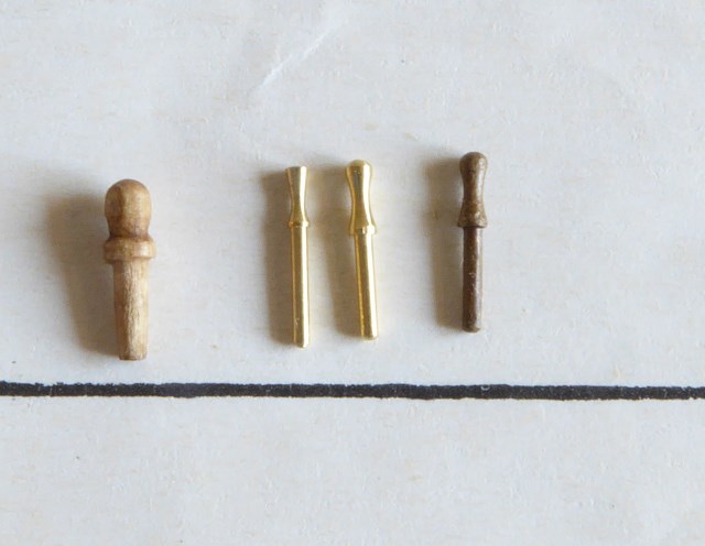
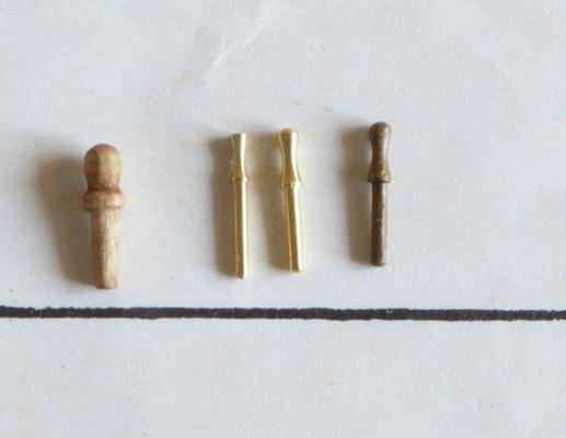
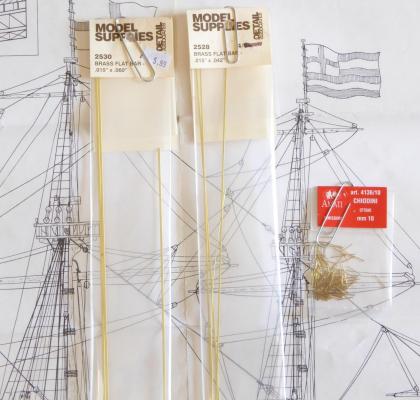
Previous posts, I debated on the use of belaying pins in the 16th century, and whether to have them on my model. Well, I decided to keep them. Without any strong evidence or opinions not to have them, I decided to have them. So, once I decided to have belaying pins, my next dilemma was what to use for belaying pins. The kit came with 8mm wood ones, and the picture below shows an example of one on them on the far left. You can see that it doesn't look much like a belaying pin should look. While I've seen larger wood belaying pins that looked decent, the 8mm ones just don't cut it. I tried modifying the wood ones, but couldn't get them consistent for such a small size. So, it seemed like I would have to go with brass ones. I had previously seen some 8mm brass pins from Model Shipways, and Billings boats, but I didn't like the shapes of them, so decided not to use them either. The second pin in the picture is a 5/16" one that I purchased from Bluejacket. You can see that the top looks like it has been chopped off. While the overall shape looks pretty good, I decided not to use these. The third pin in the picture is an 8mm one from Amati. While the shape of these aren't perfect either, I thought they looked the best, so that's what I've decided to use. The fourth pin in the picture is an Amati pin that has been colored to hopefully look more like wood than brass and metal.
-
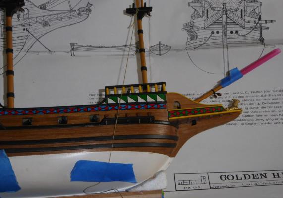
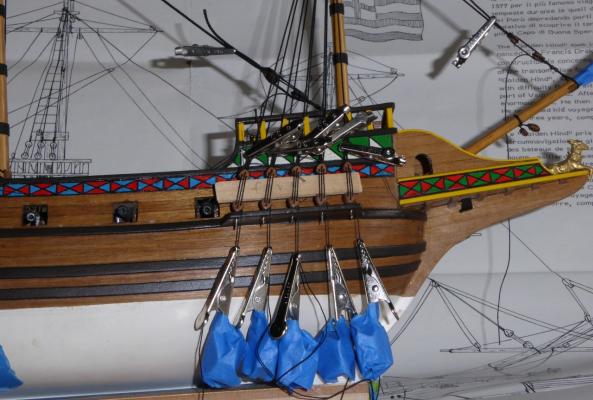
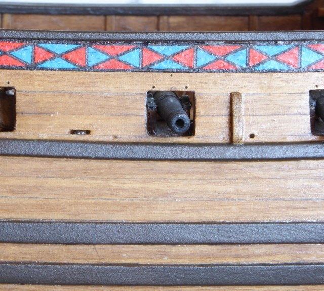
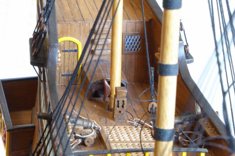
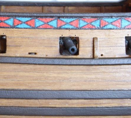
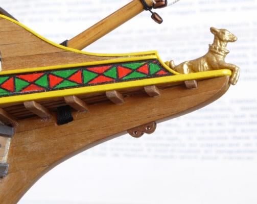
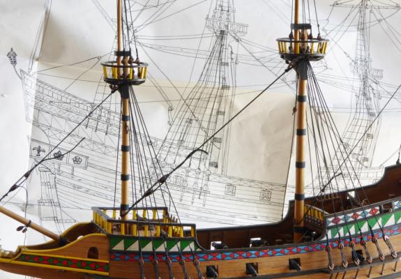
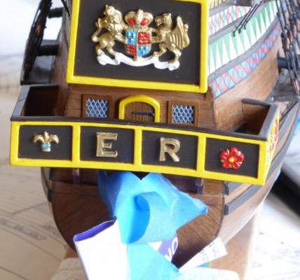
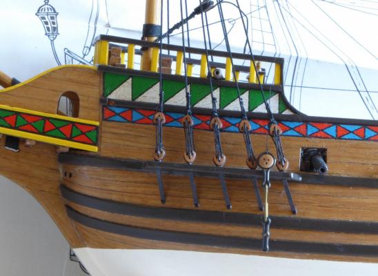
Like I said before, the kit is sail less, so I am adding sails. And because of that, I have to create all the rigging for the sails. Here are my additions for belaying the main and fore sheets and tacks. The main tack will go through the chesstree on the bulwark, then through the hole to a staghorn inside I created from my previous post. The fore tacks will go through the two holed piece I attached to the knee of the head, then through the head area and belayed to a staghorn near the bowsprit. The rectangular hole in the bulwark is supposed to represent a sheave, which seems to be a 16th century thing, and that is where the fore sheet will go, belayed to a staghorn inside. Though I don't show it in the pictures, a similar sheave is in the bulwark towards the rear, for the main sheet.

-
I don't know what is better, your beautiful modeling or your great descriptions of the rigging details!
- 249 replies
-
- 1
-

-
- billing boats
- vasa
- (and 1 more)
-
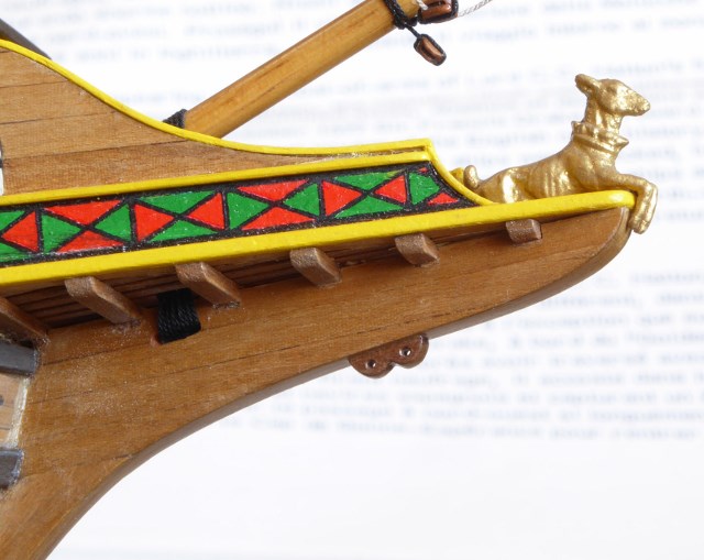
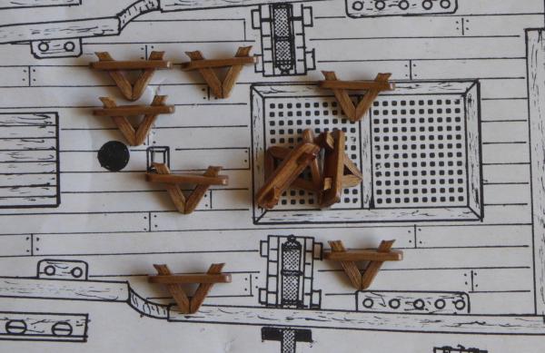
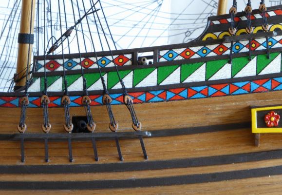
While the kit doesn't have a plan for sails, I've decided to have loosely furled sails. And since the kit didn't have any points to belay sail lines to either, I made up some staghorns for the course sheets and tacks, and some braces. While I had seen some pictures of staghorns with fancier curves than mine, I think they are adequate. The walnut pieces are made from 1.5mm thick stock.
-
Syren cleats: Darn, I wish I had known he added those with my last order from him. I remember suggesting to him awhile back about adding them to his line of products. Wood cleats smaller than 12mm are something that hasn't been available from anywhere, so I'm glad he saw the need.
-
need opinions on furled sails
rschissler replied to keelhauled's topic in Masting, rigging and sails
I think you need to do something similar to Landlubber Mike's technique for furled sails. Search for it in this section. You need to reduce the sides of the sail, so that it tapers down to the bottom of the sail. -
Floquil paint is no longer made and hasn't been for at least a few years, so it will be hard to find even old stock somewhere.
-
Nirvana: Thanks, but I want them to be consistent. I tried modifying wood belaying pins that were 8mm, similarly to what you described, but while some looked good, some were not. And when you need over 30 of them it becomes quite an effort.
-
Does anyone have any good pictures of brass belaying pins that are 8mm or 5/16", or any that you highly recommend? I've seen pictures of ones from Billings Boats and Model Shipways that have been less than perfect, so I'm thinking of Amati or Bluejacket pins now. Pictures from retailers and manufacturers sites have been pretty worthless, as far as I'm concerned. I don't know why they can't show a picture of the actual item, since they aren't consistent. I've seen nicely shaped pins in other sizes, but I've found that they can change drastically when going up or down in size. Thanks, Randy
-
It's like the wall of your house was built to fit the Santa Maria! Hmmmm...
- 274 replies
-
- 5
-
-
- Santa Maria
- Artesania Latina
- (and 2 more)
-
A great book, if you don't have it is The Ships of Christopher Columbus, by Xavier Pastor. It goes into great depth evaluating the different interpretations of the ship (forecastle and no forecastle). Also, it has a lot of information about the rigging and small details. It has great drawings to help you as well, so I highly recommend you get it. By the way, Pastor seems to lean towards the pro forecastle point of view.
- 59 replies
-
- 4
-
-
- Santa Maria
- Artesania Latina
- (and 1 more)
-
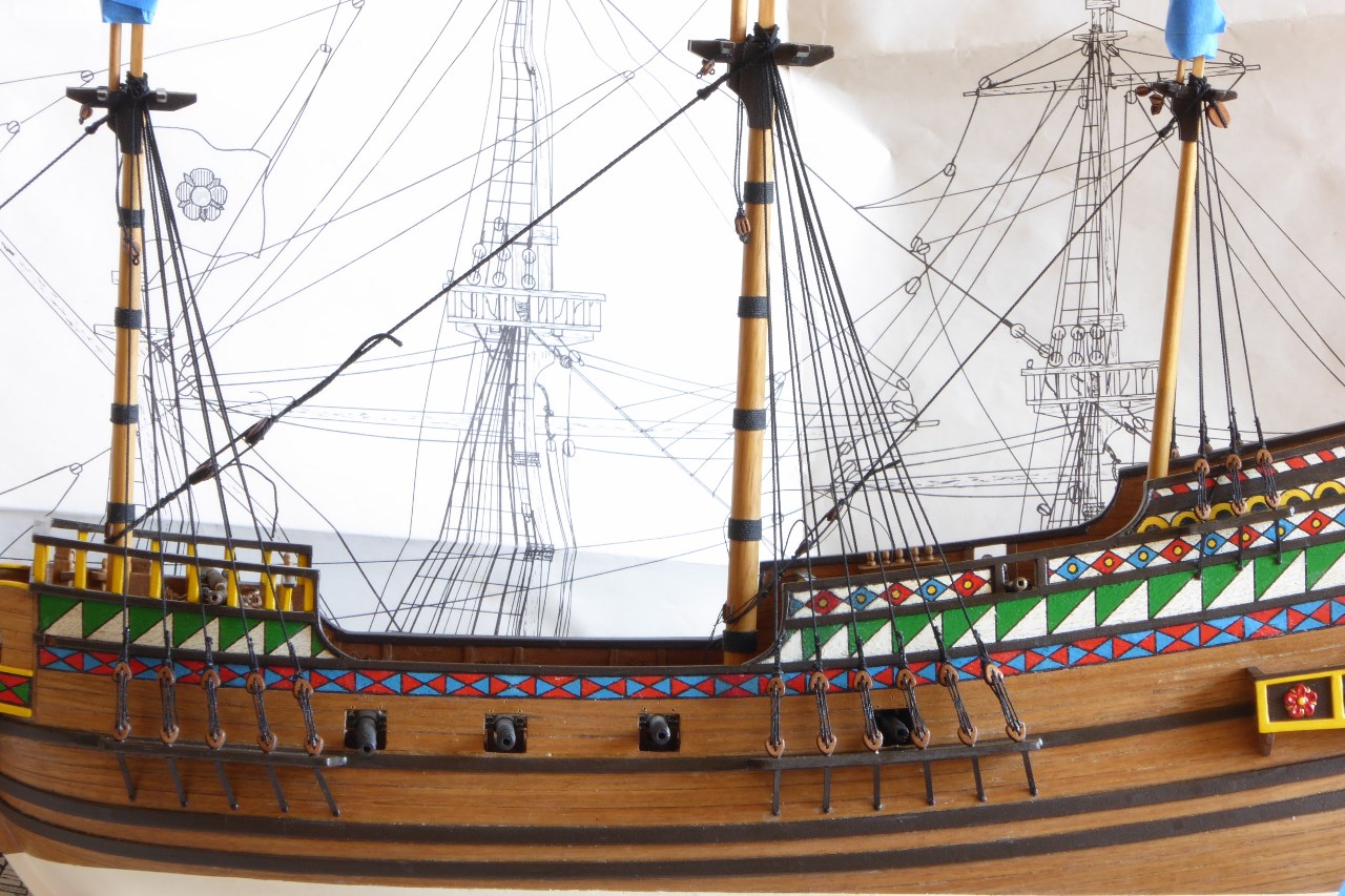
Here's something I should have noticed sooner. In W. Mondfeld's book, which I have relied on almost exclusively, devotes several pages in the beginning of his book about having a plan to build a historically accurate model ship. The section is titled "The Plan," and in it he outlines "a list of factors to show how an accurate and practical model construction plan should look." Ironically, in this section are a set of drawings that are almost exact to the model I am building, of a small English galleon from 1588. Interestingly, it also shows all the same belaying pin locations that are on my model plans. If you have the book, you might take a look. Mondfeld even has his signature next to some of the drawings. The main difference between these drawings and my kit model is that mine doesn't have sails and staghorns. Later in the book when talking about fiferails, he makes it sound like belaying pins weren't added until the 17th century, and includes drawings to show this. So, that's a contradiction.
-
Thanks Tadeusz for the Viking and cog pictures. Except, instead I think I may be more confused. Maybe there is no clear cut answer, and a ship from the late 1500's having belaying pins can't be discounted? Perhaps my plan should be to reduce the number of belaying pins as much as possible, and just have a few in the most likely places? So, if I did that, where would that be, or what particular lines?
-
Belaying Pin Dilemma? While the kit plans call for belaying pins, and I've already installed belaying pin racks on my model, I debating whether to tear them all out for the sake of historical accuracy? While W. Mondfeld's book and other sources don't provide specific dates on the early use of belaying pins, the most logical time period seems to not be until the 17th century. I don't know why ship builders didn't keep better records back in those days. LOL! The English ship Mary Rose sank in 1545, and parts of it have been brought up in the last several years. If you search on the internet, you will find a quote of "belaying pins were found during the excavation of the Mary Rose," but is this a credible source? Or, is there anything to say they were used on the Mary Rose? If you go to the Mary Rose official website, you will find pictures and information about objects that have been recovered, but nothing relating to belaying pins. The Jamestown ship Susan Constant was from 1605, and I've seen a reference that said it had some use of divers pins for belaying ropes, but even that seems vague. On the other hand, the recovered wreckage of the Swedish ship Vasa, launched in 1627, shows considerable use of belaying pins. But, that was 50 years after the Golden Hind, not English, and part of the 17th century. The two real size replicas of the Golden Hind and most different models I've seen, show belaying pins in use. However, I wonder if this is mainly because of navigational and modeling ease, or that there is nothing to say that belaying pins weren't used. Other than some vague descriptions of the Golden Hind, there is very little concrete historical information on it's design and accoutrements. That seems to be why there are such differences in the replicas and models alike. While I don't mind tearing out the pin racks on my model, I do question whether there is enough room to add all the needed kevels, staghorns, and cleats, to accommodate the lines that need belaying. I did read that some lines on earlier ships where attached to railings and shrouds, so that might help. --Randy
-
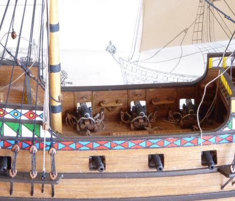
Nice deck details, but I worry that your belaying pins will be too close together, to belay any lines to them? Especially, if you have to use pins that are next to each other.
-
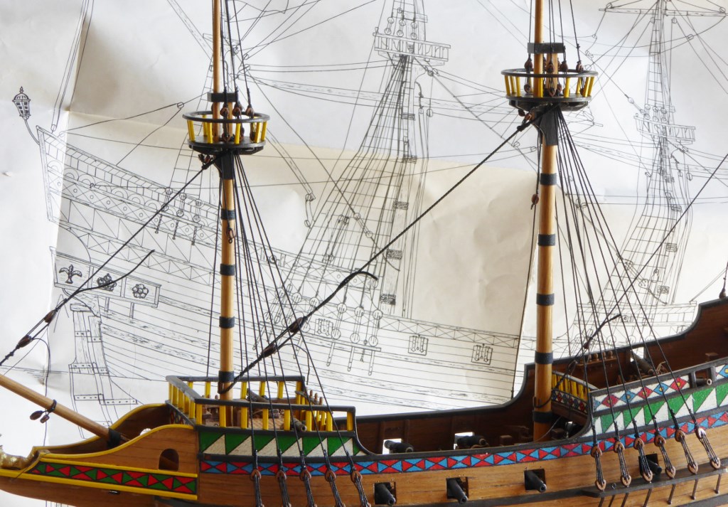
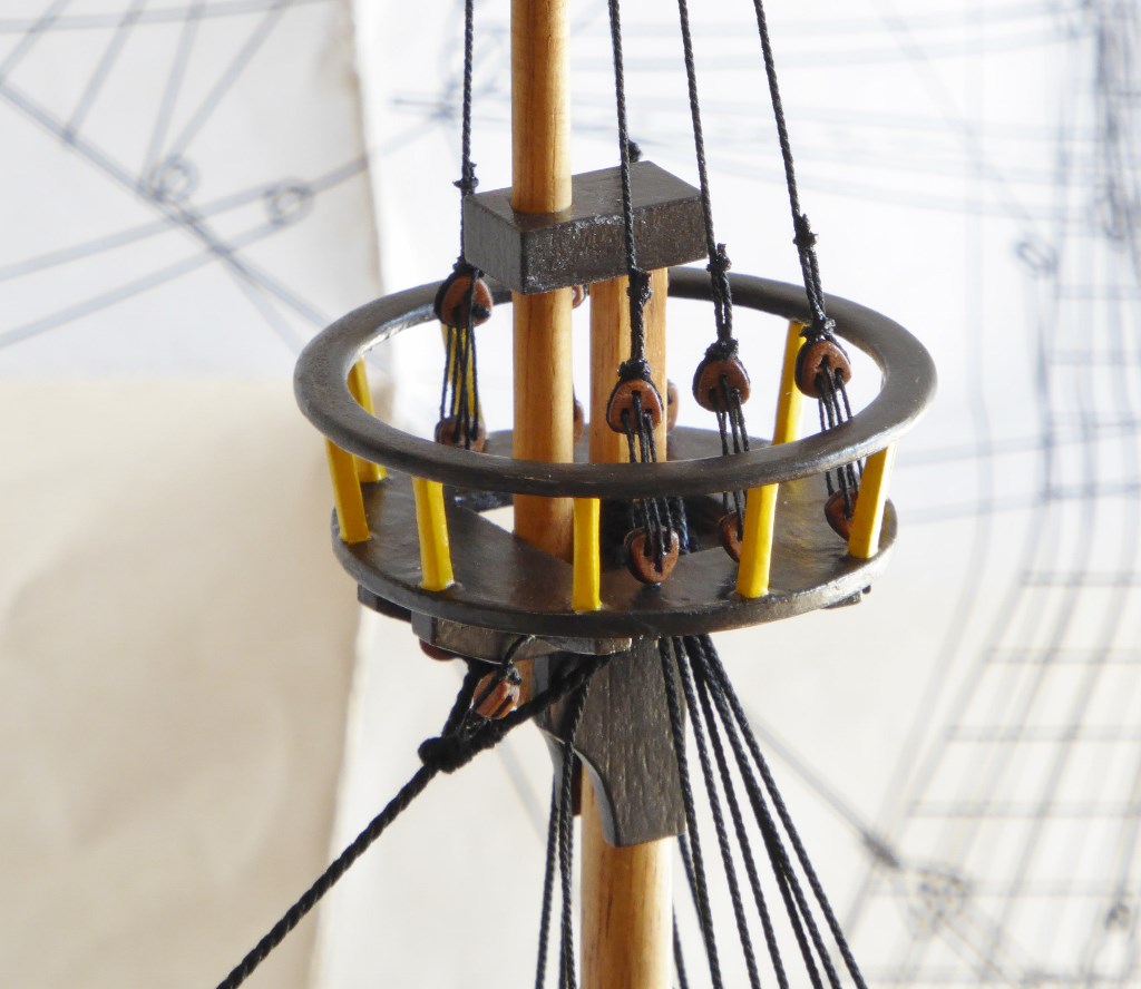
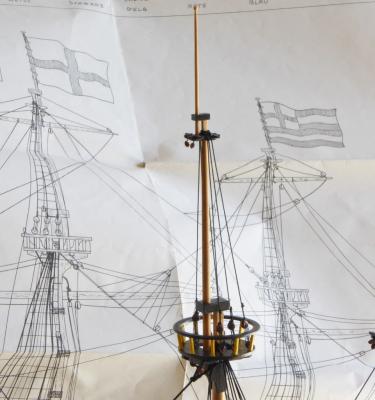
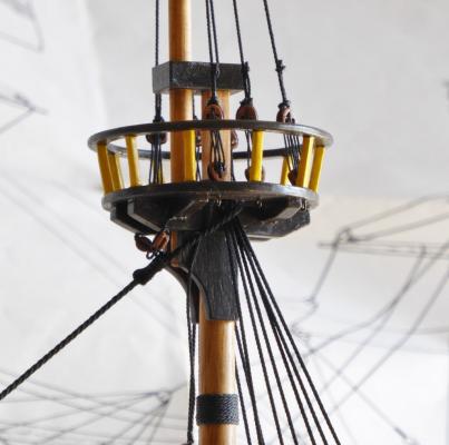
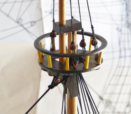
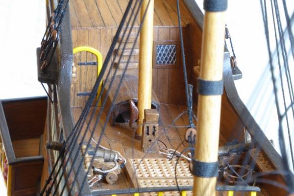
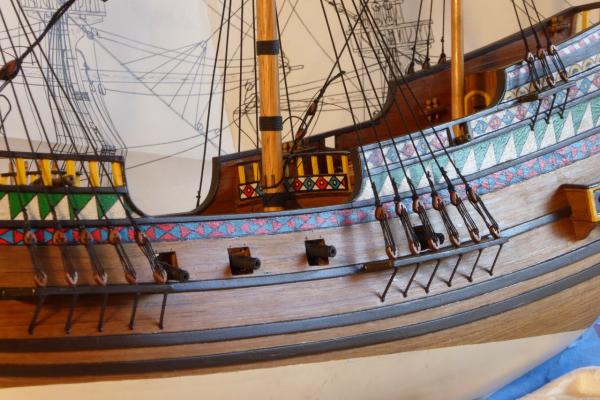
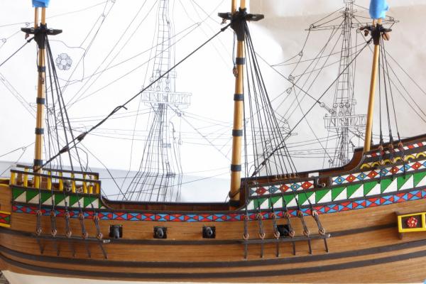
I added the tops and upper shrouds. In an earlier post, I showed how I made the tops, but hadn't painted them. I decided to paint them to match the lower railings. A deviation I made from the kit plans, was to attach the lower deadeyes to the floor of the tops, instead of the top railings of the tops. I just thought that was a better decision, and don't think it detracts from it. Yes, I know that I still need to attach the ratlines and futtock shrouds, but that and some more work on all the stays should complete the standing rigging. --Randy
-
Hi Tad, Nice picture of you next to the Hind. I've always found it interesting that this replica, and the other one at Brixham are very different, as is my model. I've read that the original Golden Hind sat docked in retirement for almost 100 years as a historical attraction, and yet no one painted a picture of it or made any drawings to preserve a historical record of it.
-
That looks really nice! It's amazing how small it is.
- 40 replies
-
- 1
-
-
- plastic
- r.c. anderson
- (and 2 more)
-
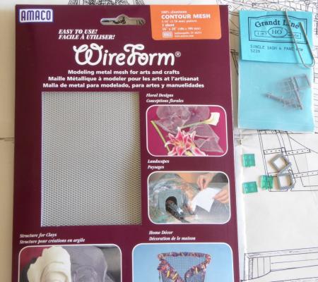
I installed the three windows the kit called for. Two on the transom, and another on a bulkhead toward the rear. If you look at the first picture, you will see the green kit windows. I thought these were weird and the proper windows for the time period would have been Tudor windows. Tudor windows used diamond shaped panes of glass, inserted into lead frames. What I ended up using, you can see in the rest of the first picture. On the plastic window frames, I cut away the sill and narrowed the edge, so it didn't look like a modern window. I then painted them to look like wood. I cut a piece of the mesh, and coated one side pretty heavy with Microscale Kristal Klear to form the glass. It has the consistency and look of white glue, but when it dries it is gloss. If too much seeped into the other "good" side, I wiped it away with my finger. When dry, I then cut them to size to fit the window frames, and glued them into cutouts made on the ship hull.
-
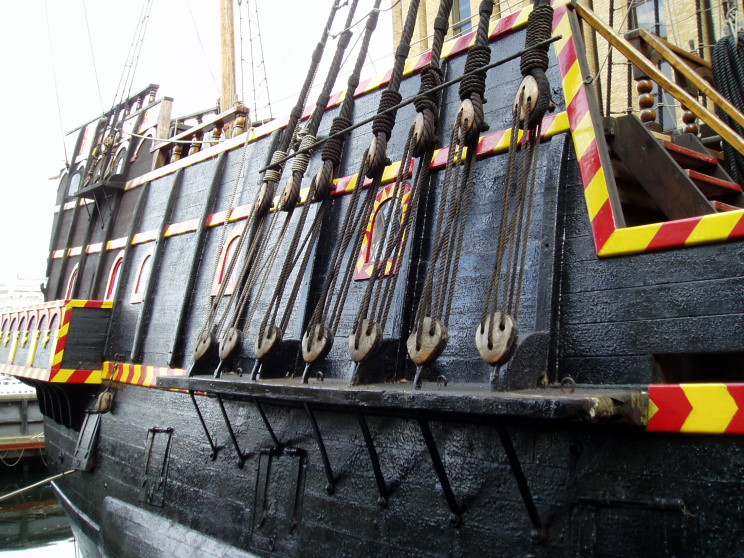
Here are my finished chainplates, triangular deadeyes, and shrouds. The real ship picture shows a shot from one of the two (very different from each other) full scale replicas of the Golden Hind. This is what I decided to model my chainplates from. You can see that it is just an iron strap with one bolt head securing it to the hull. The first picture shows the flat brass bar from Detail Associates and Amati fine nails that I used. For the chainplates on the smaller deadeyes on the rear, I had to file down the diameter of the heads of the nails somewhat, so they wouldn't be wider than the smaller brass bar used there. For attaching the chainplate straps to the channels, I originally planned to solder them to the soldered ends of the brass wire deadeye wraps that protruded through the holes in the channels, but I used CA instead. I had to do some filing on the wire ends to get them the right angles to the chainplate straps. The second picture shows shows an example of the deadeyes and chainplate assembly that came with the kit, in contrast to what I did for my model. As you can see, the kit parts look very oversize and bulky, plus the single strap I used is more appropriate for the time period of the Golden Hind. In my last post, I showed the predrilled holes I made for the chainplate nails, by using the line to find the correct angles. Even so, I had a adjust a few of the holes, to keep the chainplate straps aligned with the shrouds, when looking at them straight on. Also, since each chainplate was at a different angle and length, I had to fit each one individually. --Randy

-
That was an awesome job on your Virginia Sloop! I encourage you with your body rebuilding. From my experience, the best way to keep at it and motivated, is to make it routine. At least three times a week, and hopefully five to really get a benefit. Do it the same time of day, so that it becomes automatic and less chance of talking yourself out of it. For me, the best time was immediately after work, before I had a chance to sit down a relax, because once you've done that it's much harder to get going again. I look forward to your Civil War build. That should be interesting.
- 831 replies
-
- 5
-
-
- Armed Virginia Sloop
- Model Shipways
- (and 1 more)
-
Yes, I'm finally back! Because of travel and some other things, a few months went by without dong anything on the model. Also, I was entering an intimidating phase, involving the deadeyes and shrouds. The kit came with round deadeyes and I knew that it really needed triangular deadeyes, because of the time period. Commercially, 5mm and 7mm triangular deadeyes are the only premade ones available. I needed some as small as about 3.5mm, so I was in a quandary. Fortunately, Chuck of Syren was able to custom make all the deadeyes I wanted at whatever sizes I needed. They are the type that are a kit: they have to be glued together, then processed (rounding the edges in a Blockbuster) and stained. It took awhile to figure out what I needed, realizing that the processing reduces them by about .40mm in height. Shown by the first picture, I used a piece of line to figure out the proper angles to the channels, and the holes for the chainplates. I used brass wire to wrap around the lower deadeyes, then twisted the ends, then soldered them and inserted in the holes in the channels. The lower picture shows the piece of stripwood that I used to keep the deadeyes at a uniform distance. I always hate models with upper deadeyes that are extremely uneven. The lower clips have steel nuts taped to them to weigh down the lanyards, until I could tighten them up and put a drop of CA on last hole to secure them. One difficulty with the triangular deadeyes, is that it is harder to tighten the shrouds around them, as opposed to round ones. Maybe that is why shipbuilders eventually went to round ones? Hopefully in a few days, I can update with the finished shrouds and my scratchbuilt chainplates.