


KeithAug
-
Posts
3,867 -
Joined
-
Last visited
Content Type
Profiles
Forums
Gallery
Events
Posts posted by KeithAug
-
-
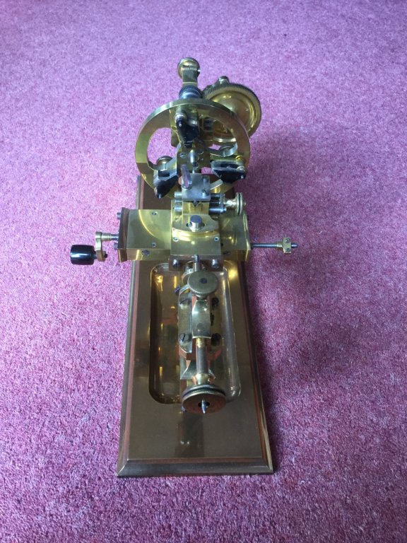
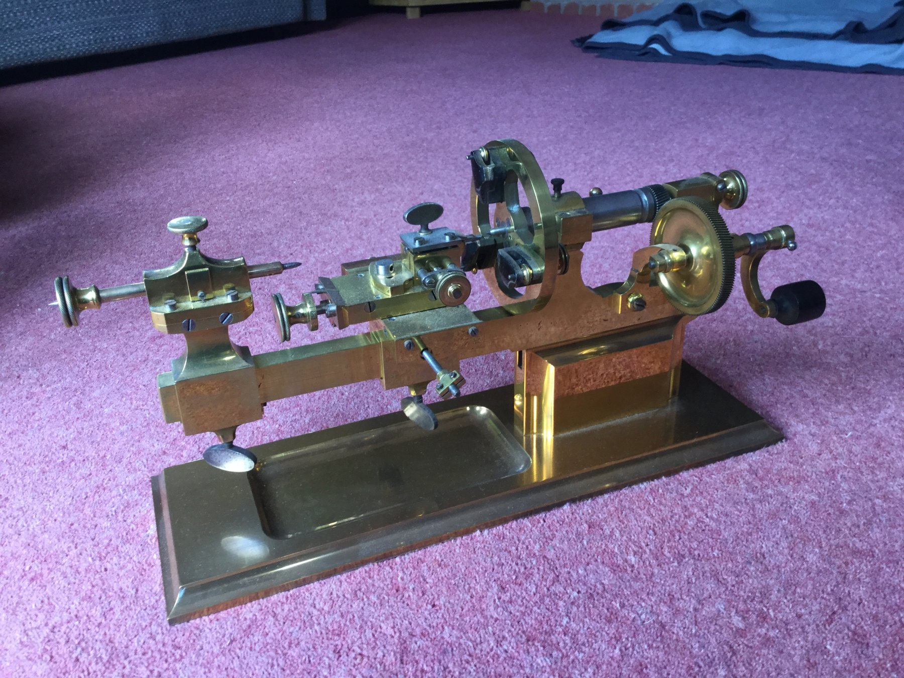
Hello Martin
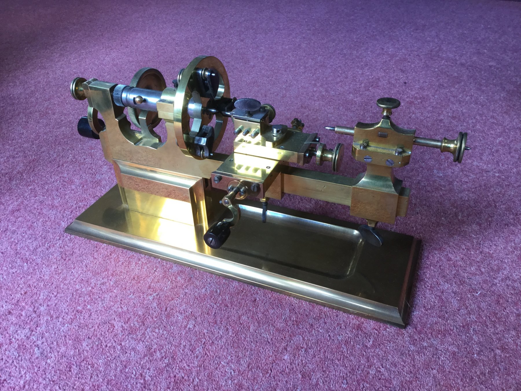
Your lathe dates from about 1850.
I also have one.
 They were primarily used for making the various mounting plates that sit within the watch.
You can see more detail here. http://www.lathes.co.uk/swissuniversal/
lovely model by the way.

- Tony Hunt, michael mott, jud and 9 others
-
 12
12
-
All looking very realistic Nils. Great job.
- Mirabell61, cog, Omega1234 and 1 other
-
4
-
-
Thank you John.
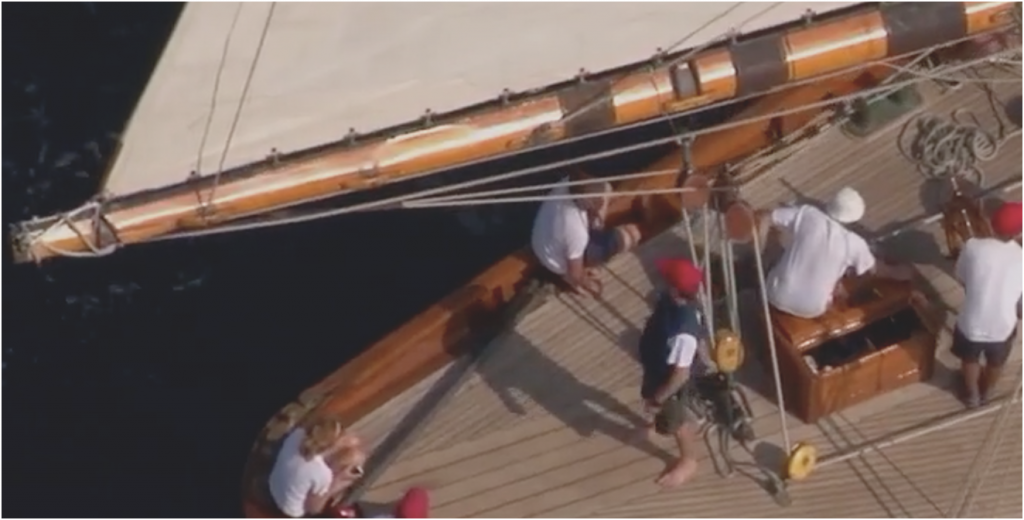
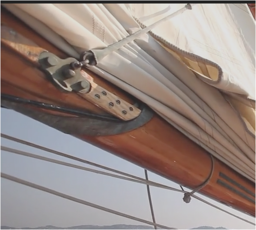
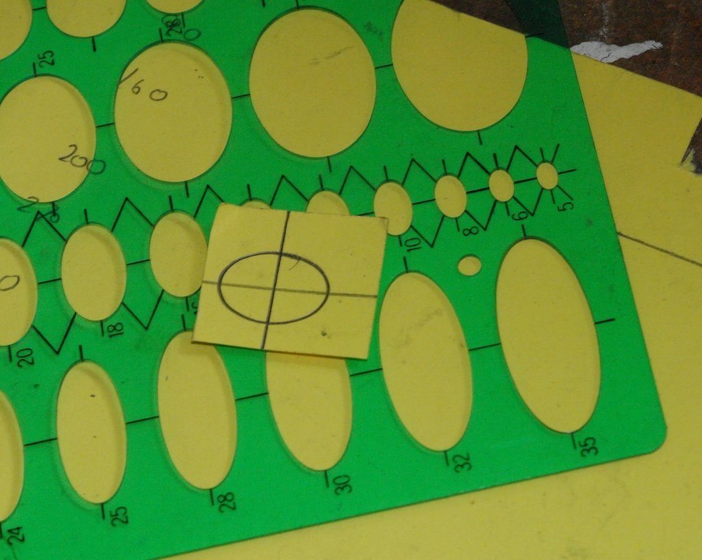
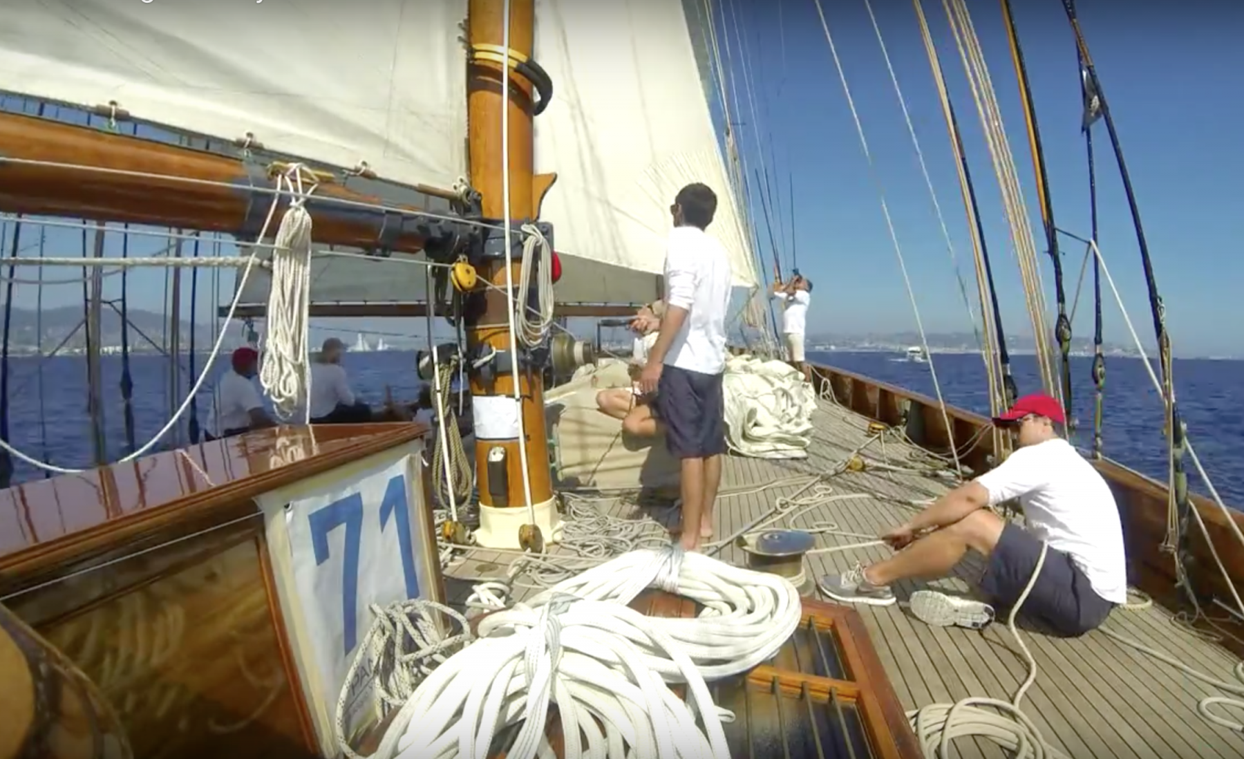
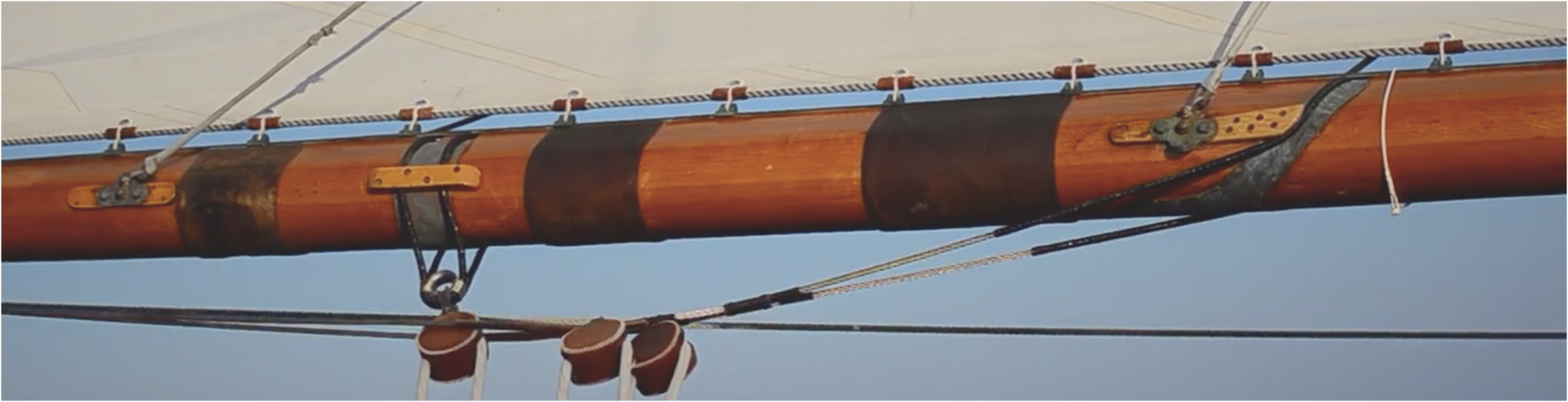
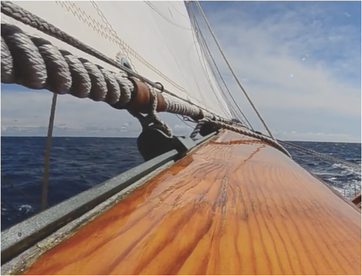
Richard - I have used that video a lot. The image at 2.15 is a bit vague so requires some interpretation. It's the image below - cleaned up as best I can using photo processing
I am assuming that the main boom shares some common design features but I can't see any signs of the outhaul on this image.
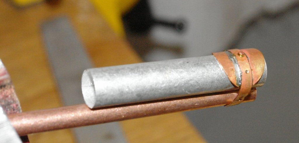
The image that Infer the design is the one below. The tight line that is below the boom passes through the pulley before winding on to the mast winch. I'm not sure what this would be for if not an outhaul.

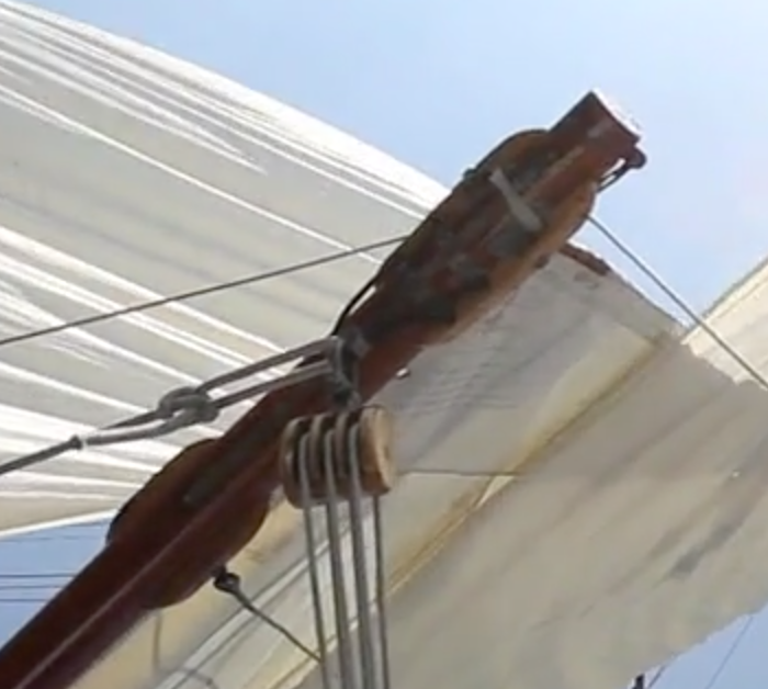
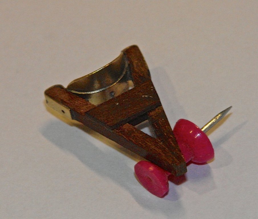
However to add to the mystery I also have this image which shows a twin (triangular) rope arrangement going back to two eyes on the ring at the end of the boom.
I bet someone will have a good explanation for the images?????
- shipmodel, GrantGoodale, Nirvana and 2 others
-
5
-
Richard, Greg , Per. Thank you.
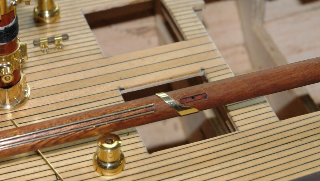
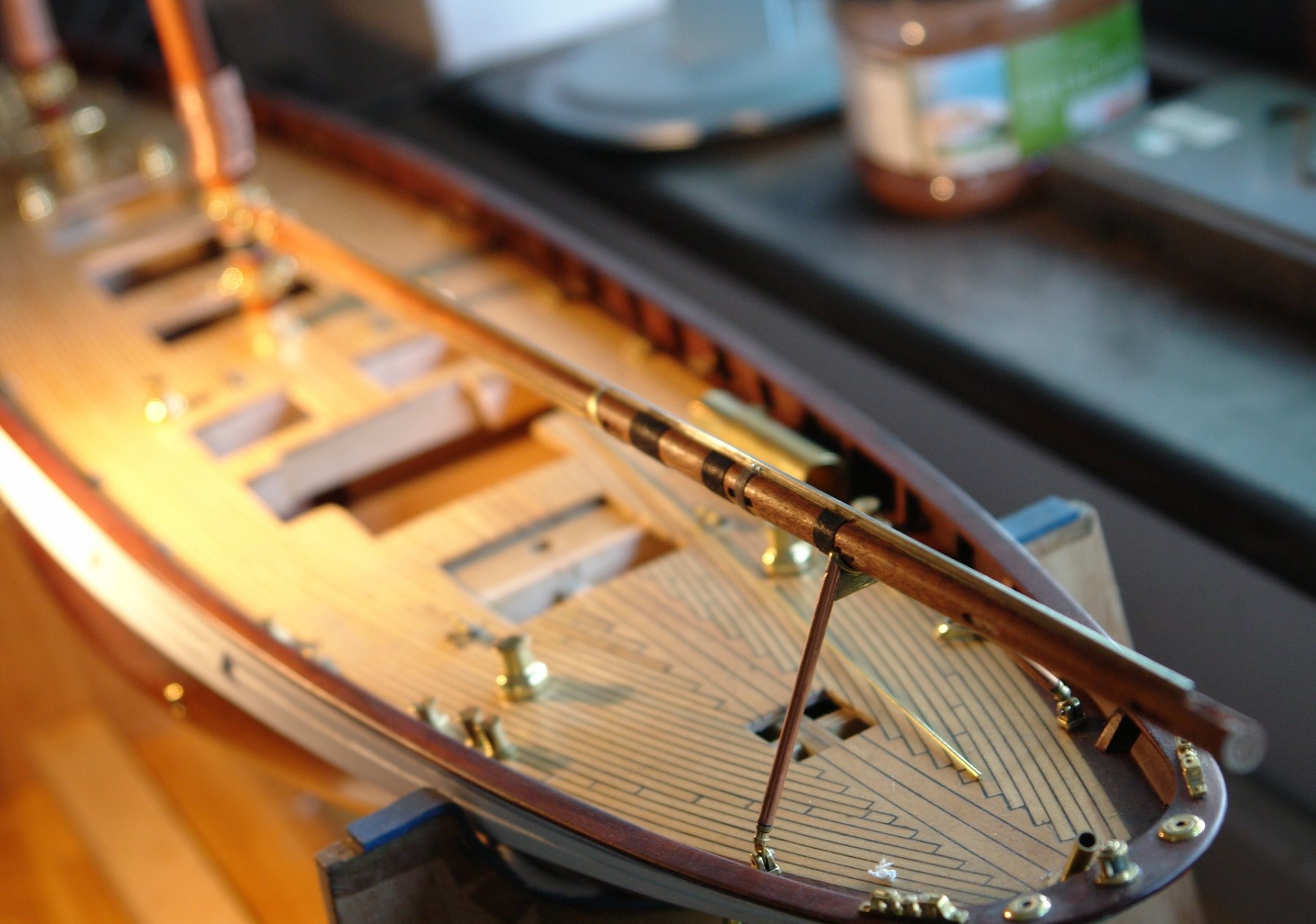
Further progress on the boom:-
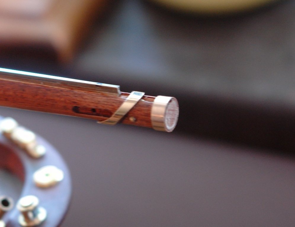
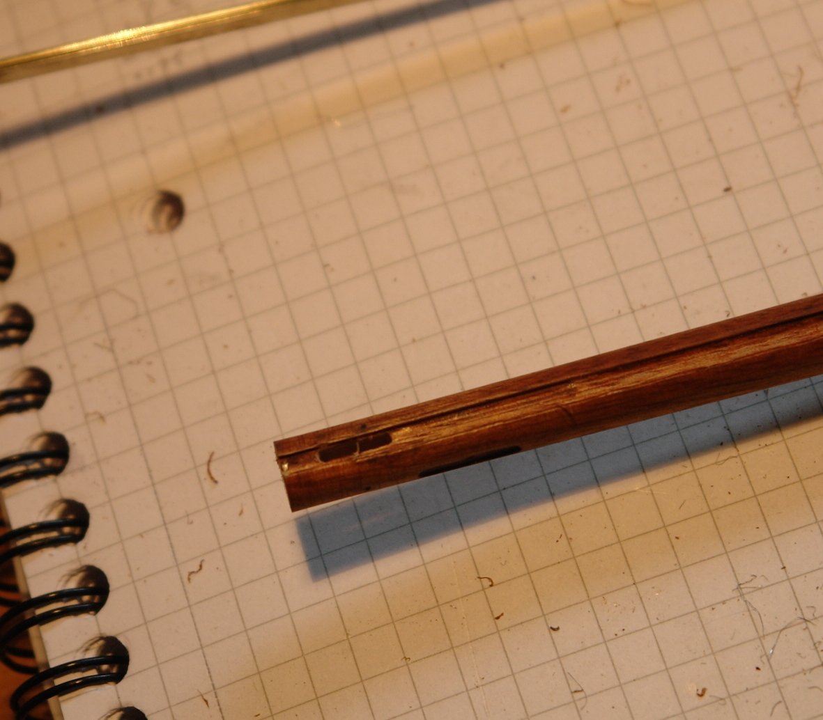
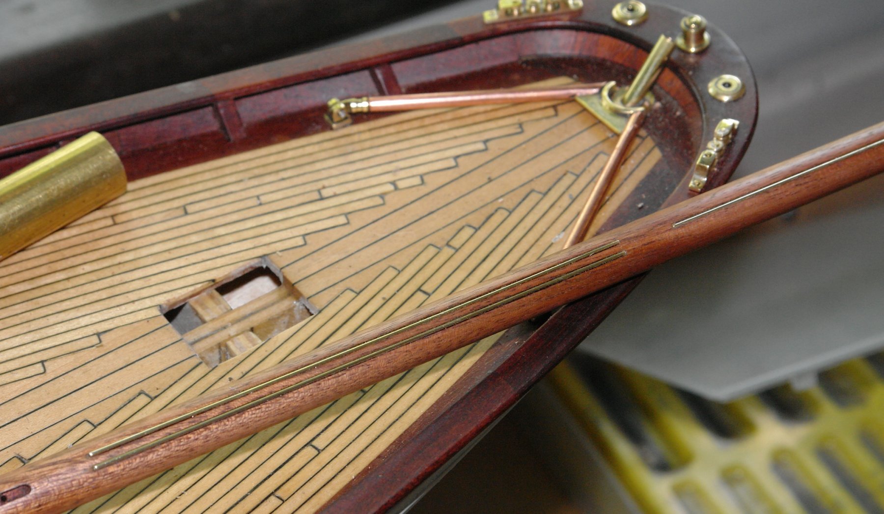
The detail at the end of the boom is minimal both on the plans and on the web. The mainsail must have an outhaul line and on some photos I can see a line running the length of the boom to a block and winch on the main mast. I surmise that this is the outhaul in which case the end of the boom must have some sort of pulley wheel. I decided therefore to slot out the end of the boom to take a .25" dia x .04" wide sheave.
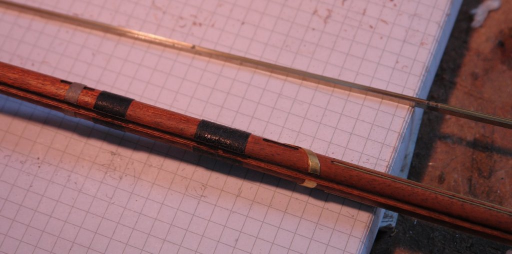
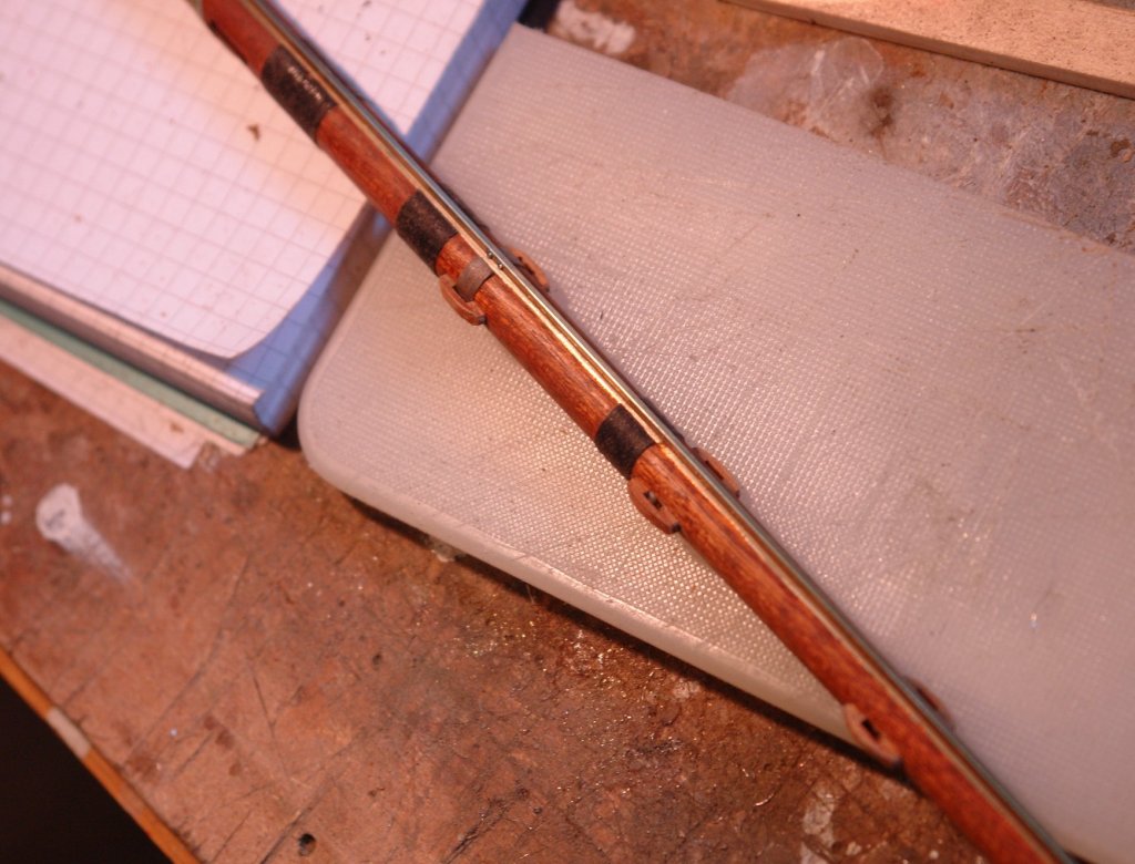
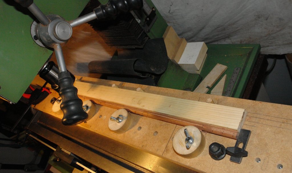
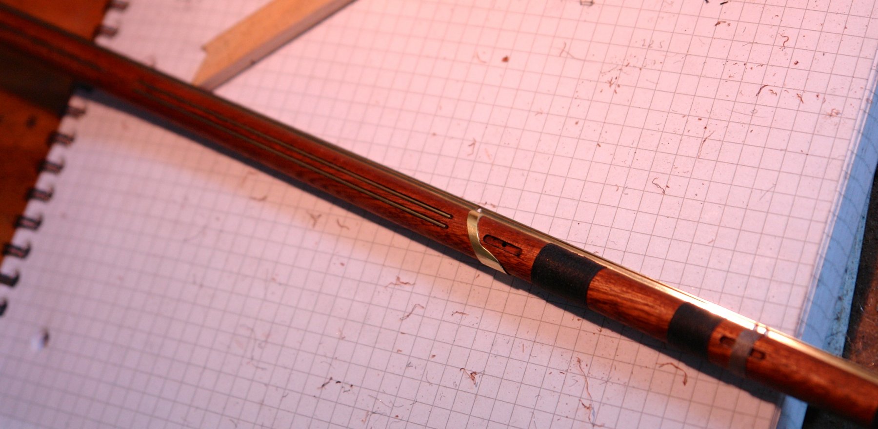
The boom has 4 bindings at positions along it length. One is grey while the others are black. A raid of my wife's sewing box produced the required thread and I wound it by pacing the boom in the lathe (rotating at 60 rpm) with the thread being hand fed. I fixed it in place by wiping on some CA glue. The binding was then cut away across the slot (milled earlier) to take the track.
The track was then machined to fit over the various boom fittings and holes were drilled in it to pass through the various strops and lines. The track was glued into the slot using CA glue.

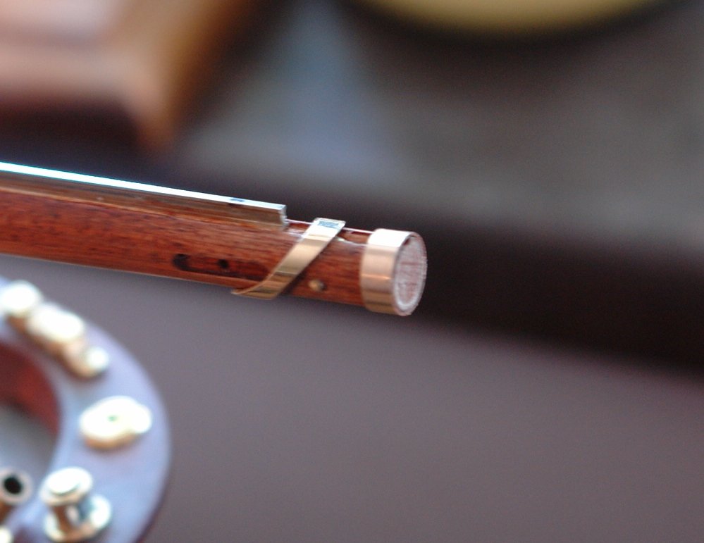
The end of the boom was then finished by adding a further strop rubbing strip, sheave and end reinforcing hoop.
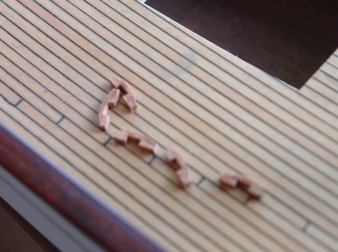
Along the boom are various attachment points which were made from mahogany.
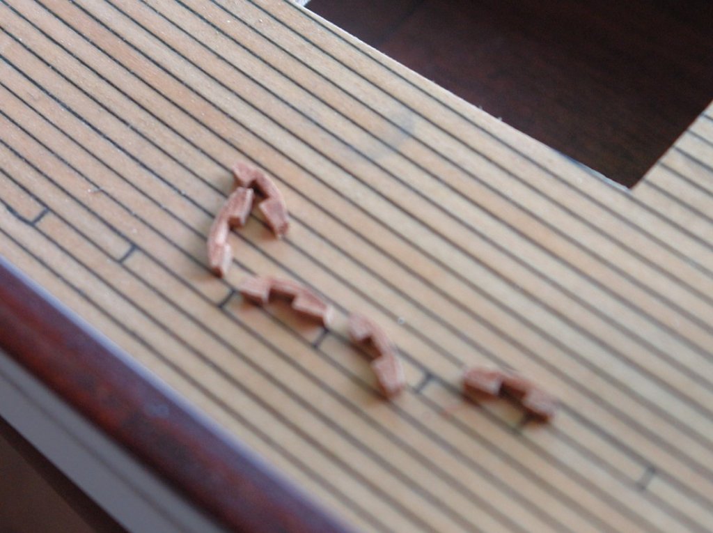
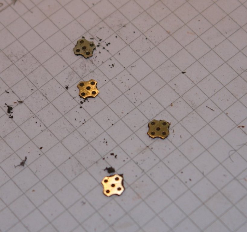
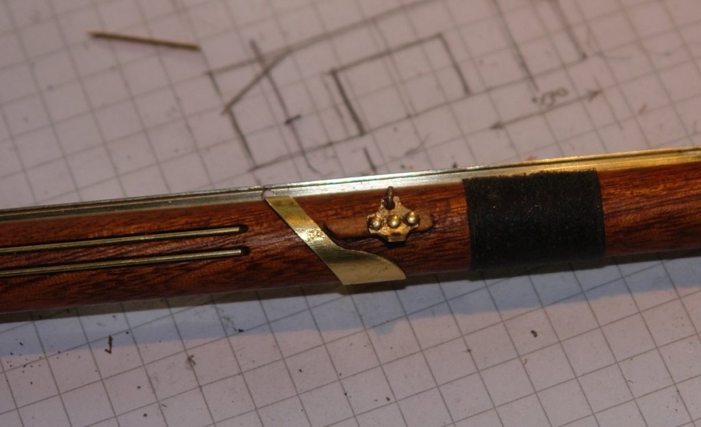
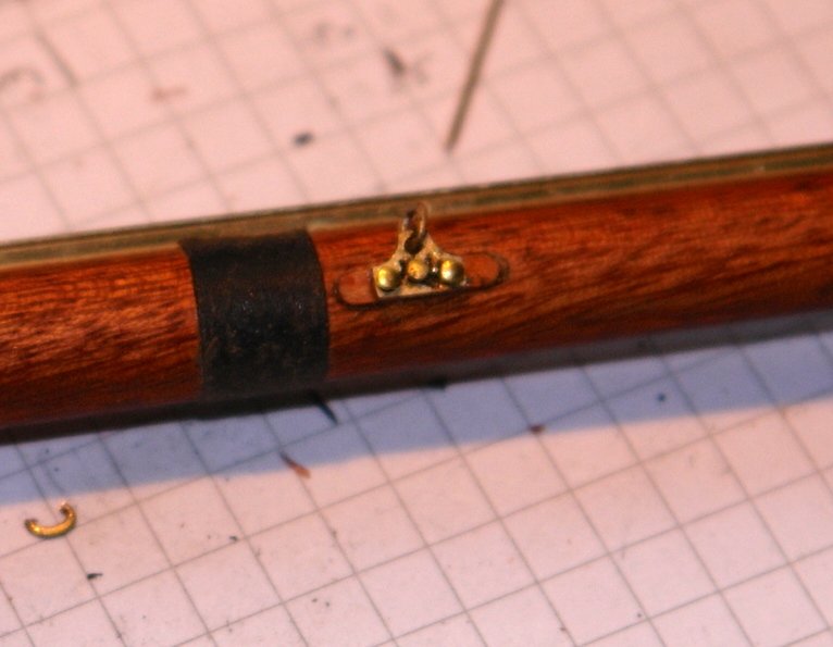
I also needed to make an attach some very small (at model scale) brackets. These were cruciform in shape and were made on the mill. They are about .2" x .2".

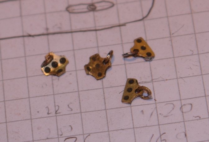
The brackets were then attached - pinned in place and glued with CA.

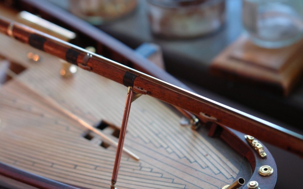
Every time I look at the boom I find more detail. I thought I had finished but then discovered a couple of cleats mounted at the mast end. A job for tomorrow!!! I also need to think about making the 60 sliders which are approx .080 inch wide and need to be slotted to run on the track. They are complicated little devils and I need to work out how best to produce them efficiently.
-
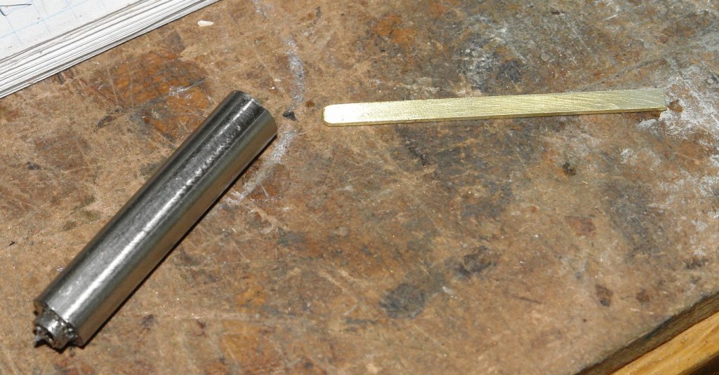
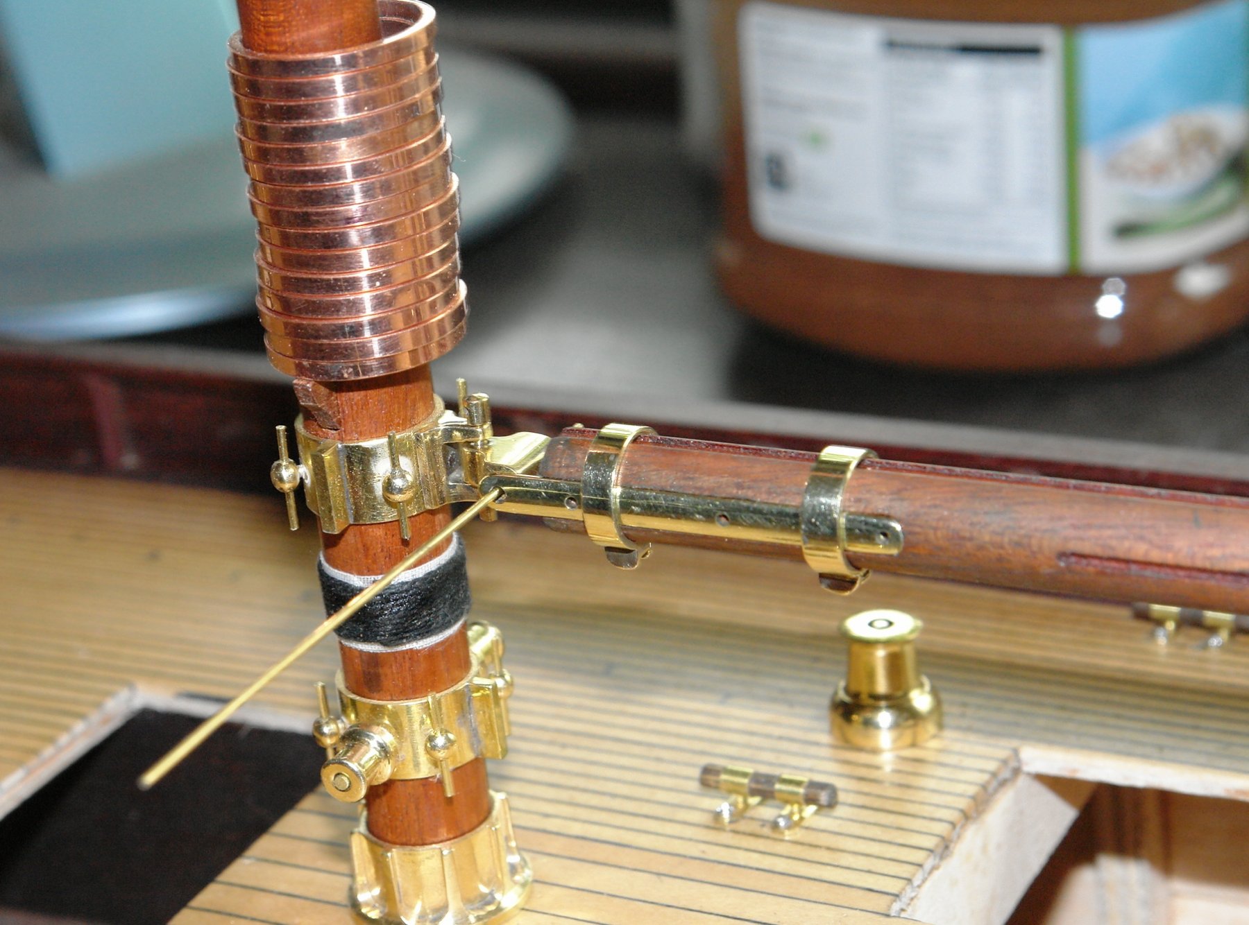
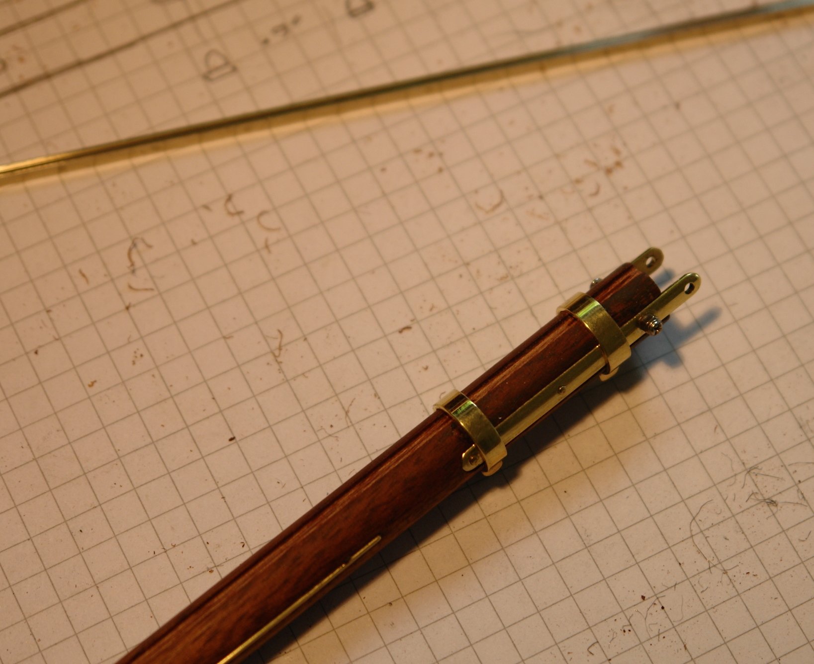
After a bit of an enforced break I managed to get a couple of days in the shop for the first time in 2 weeks. I started from where I left off with the machined main boom.
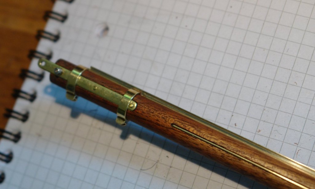
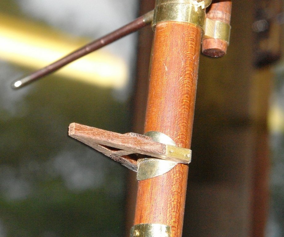
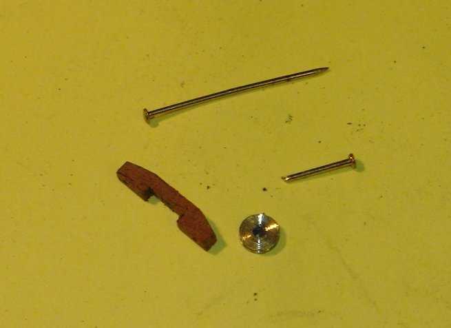
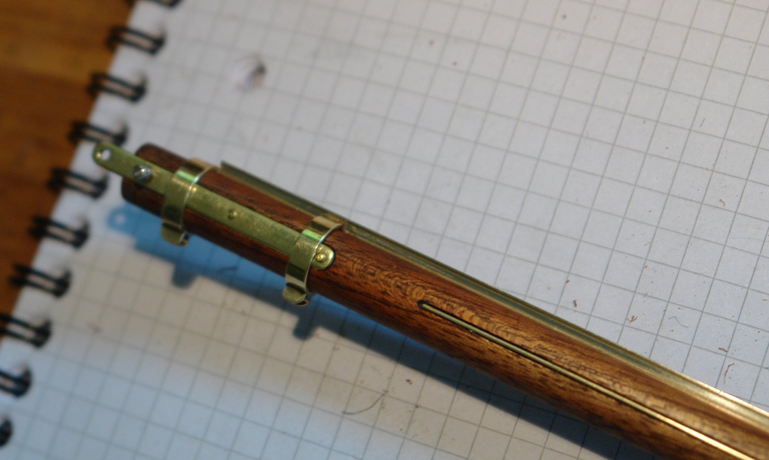
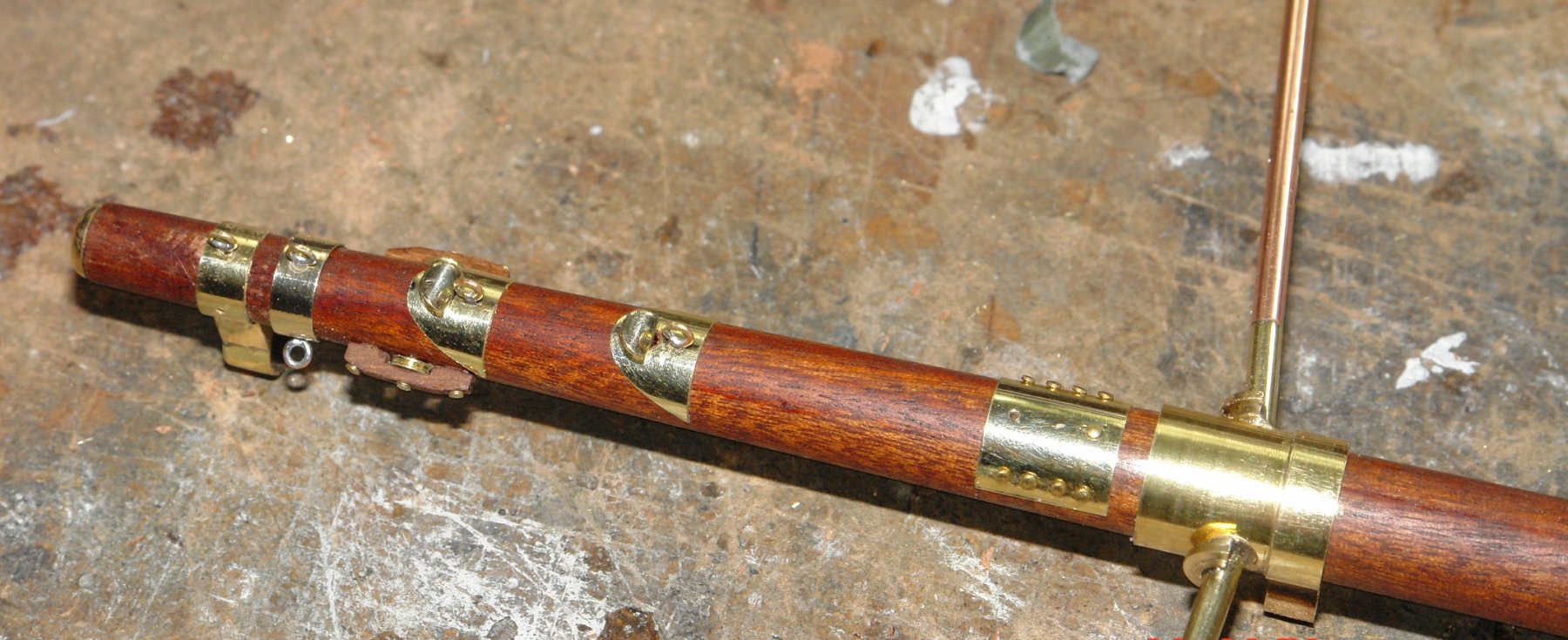
I needed to make the straps which attach the boom to the goose neck and the hoops which hold them in place. Because the straps fit inside the hoops the outside surface needed to be filed into a curve. I machined slots into a turned bar to hold the straps and act as a filing guide so I could get the correct shape. The hoops were turned on the lathe and the flanges were simulated by soldering on a bit of U shaped channel. The straps are .100" wide to give some idea of scale.


The assembly was finished by simulating the rivets using pins and making the securing bolt from my pack of spectacle repair screws and nuts.
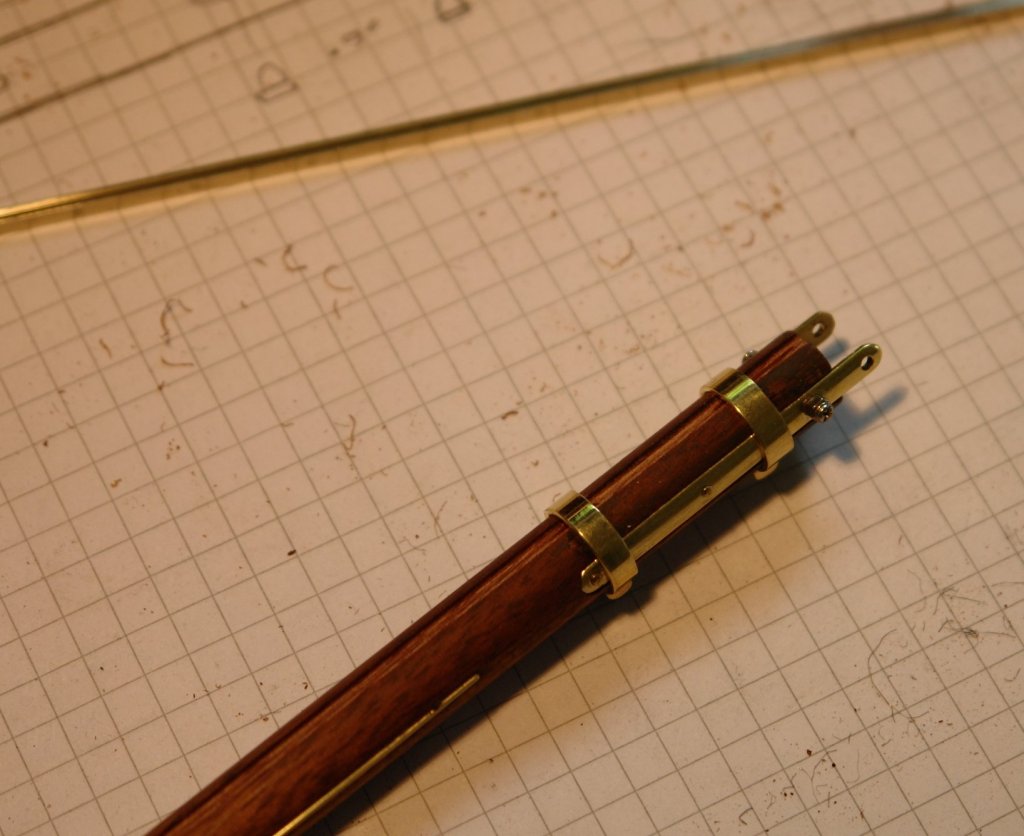
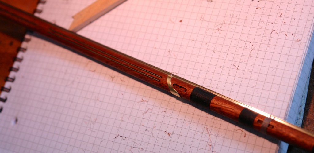
I then cut some .025" diameter brass wire and inlaid it to simulate the rubbing strips.
The boom also has rubbing hoops where the boom strop bears against it. These were cut from tube, partly on the mill, before finishing with a piercing saw and needle file.
- tadheus, Dziadeczek, tasmanian and 6 others
-
9
-
its a bit late now but it might be worth noting for the future.
Mix a little body filler and spread it thinly with a flexible (plastic) spatula - about 1.5 to 2 inches wide. Limit the area being filled to about 4 inches by 8 inches. This should mean that you get the mixed filler on before it starts to go off.
Rub it down until smooth using a coarse emery cloth - 60 or 80 grit.
Apply another thin coat and repeat.
Carry on this way until the whole hull has been done - it may take 15 to 30 applications.
As you reach the later applications you should move to finer emery cloth 120 to 180 grit.
-
-
Hi
if you need any more hints or photos please ask. I didn't take any photos of my build as it was pre internet and in the days of film cameras. However as the model is still on the shelf more photos are easy to take. I hope you enjoy the build, take you time the fun is in the journey.
By the way I used car (epoxy) body filler to fill the low points in my planking and sanded it out using a cork sanding block. It's fairly easy as long as you take care and use long steady strokes along the line of the hull.
-
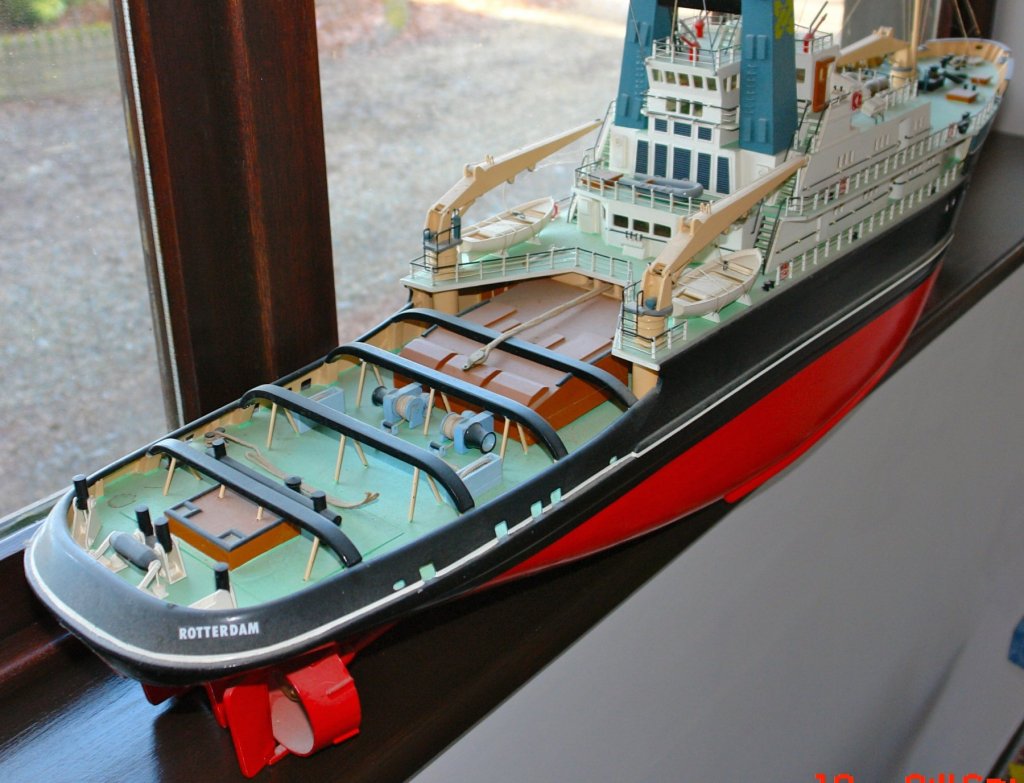
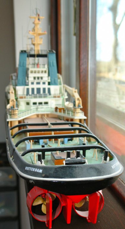
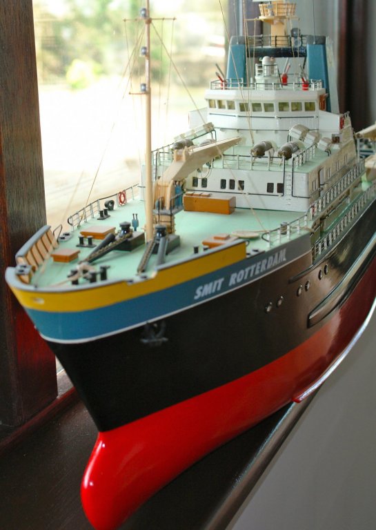
Hello Frozen Rabbit
Smit Rotterdam was my first kit model so I read your post with interest. My build was completed about 30 years ago and like others I see many differences between the hull that I built and the kit you are building. The vast majority of my hull was planked in strip wood no wider than 5/16 inch. It seems to me that what you are having to deal with is a much more difficult construction method, presumably "value engineering" on steroids. Good luck.
- cog, Tallshiptragic, tasmanian and 4 others
-
7
-
A bit of an update on a not very productive week.
I started work on the main boom. I have a bit of nice detail from photographs:-

 The rubbing strips are quite a nice feature which it would be good to reproduce (right on the above photo and left on the photo below).
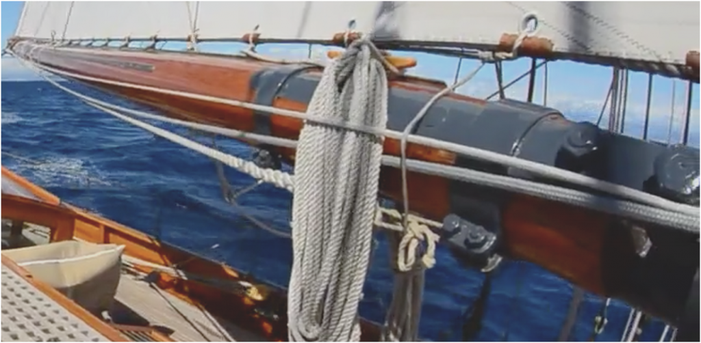
The track runs for about 90% of the length of the boom and has 30 sliders on it.

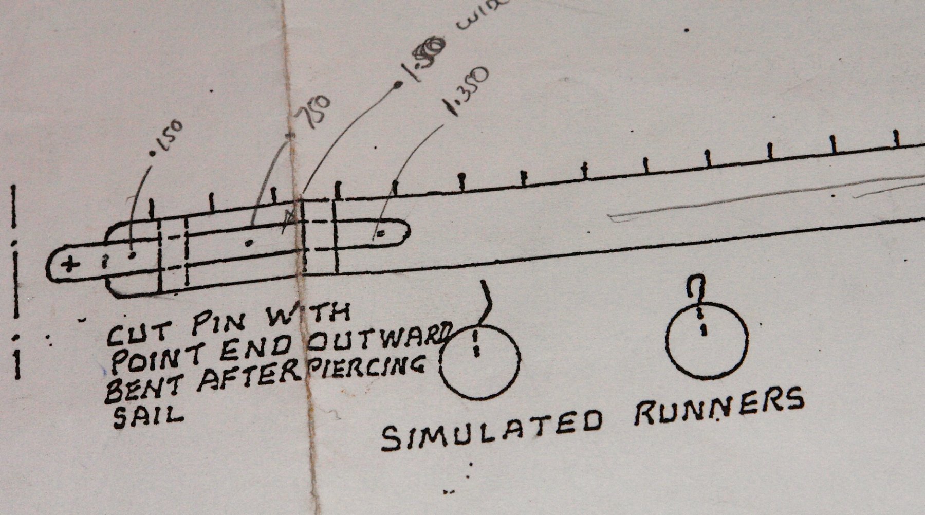
The plans approach to the attachment between the boom and sail is a bit of a joke!
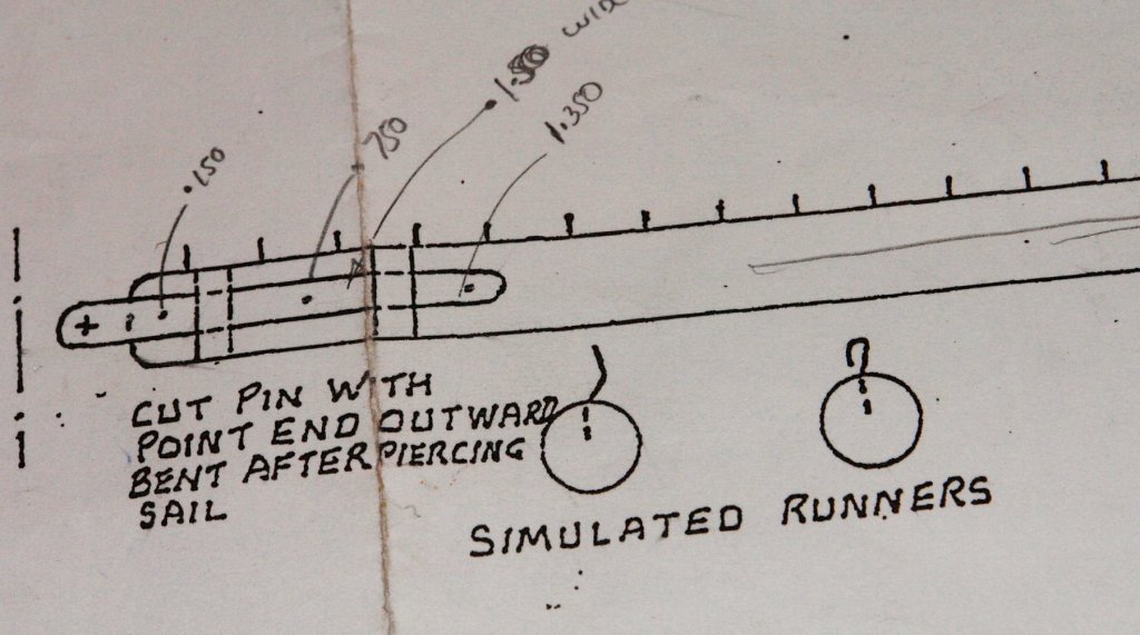
I think reference to "simulated runners" is a misuse of the word simulated!
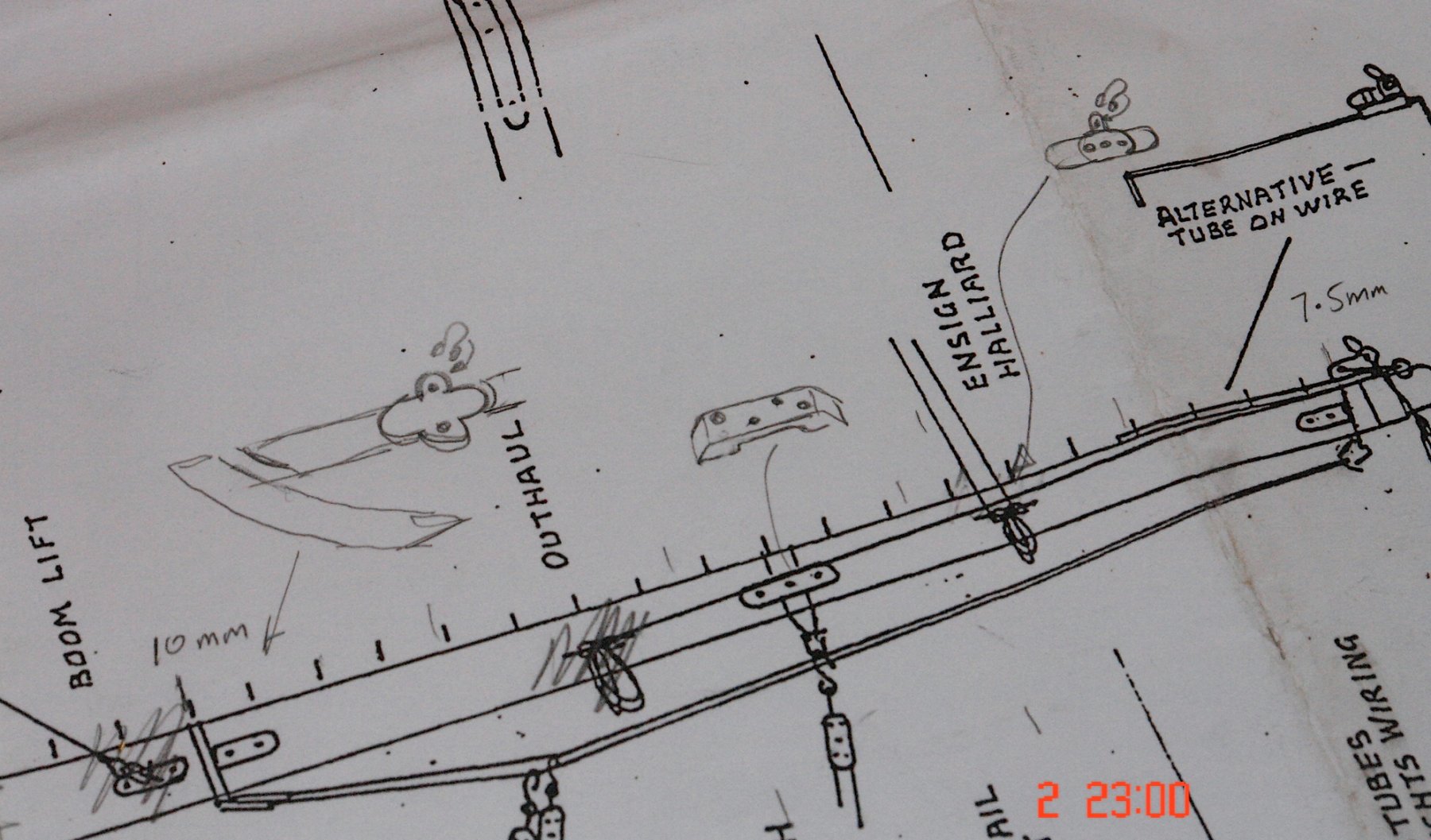
The detailing of the boom is also somewhat lacking. On the plan below you can see I am starting to sketch on extra detail.
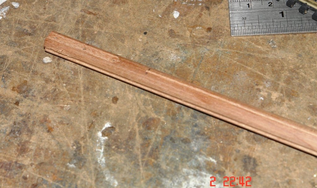
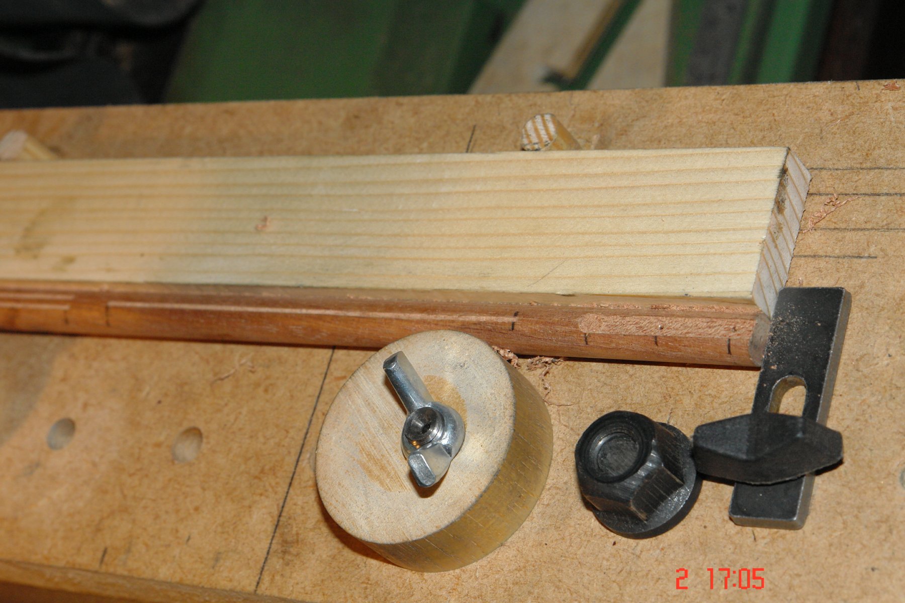
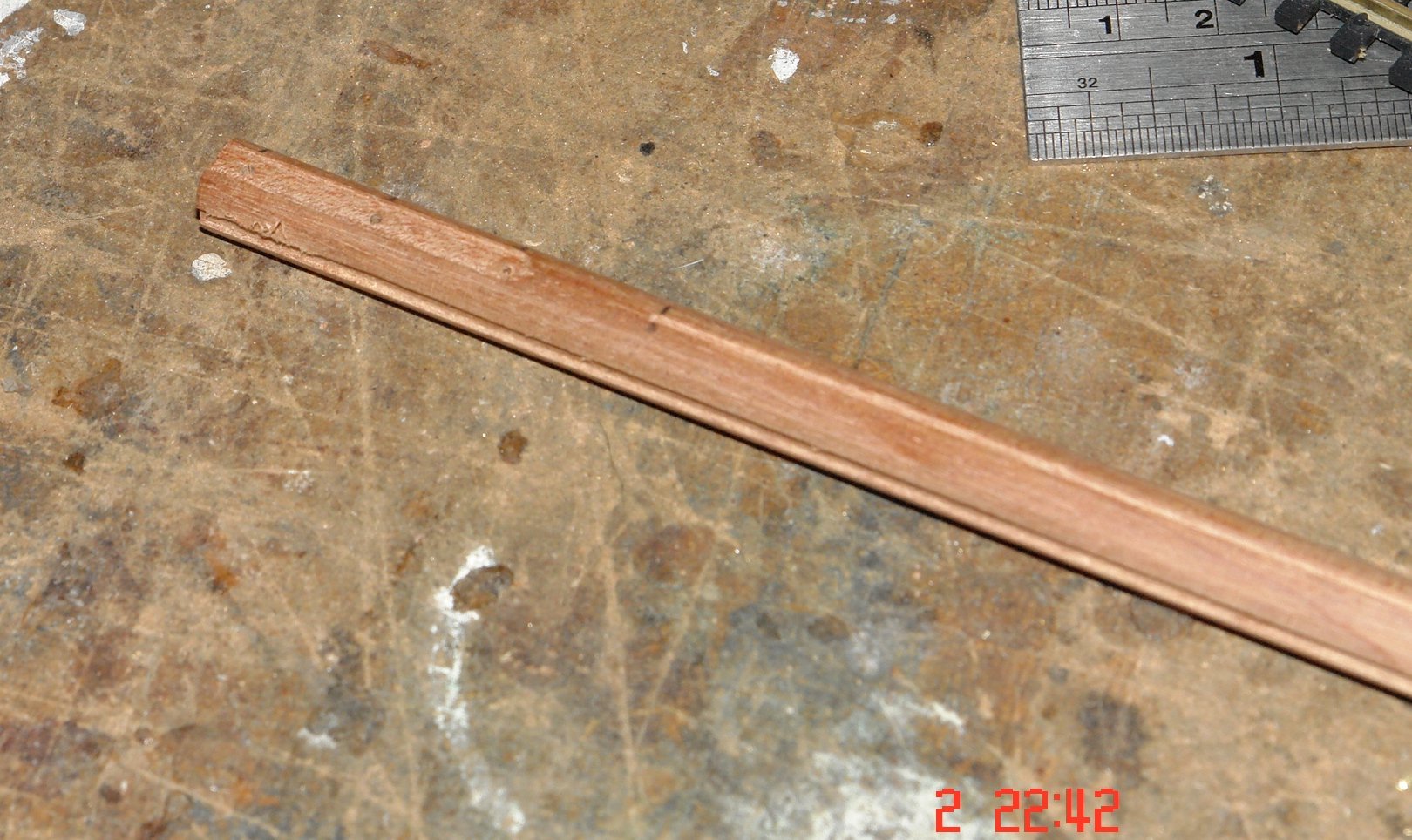
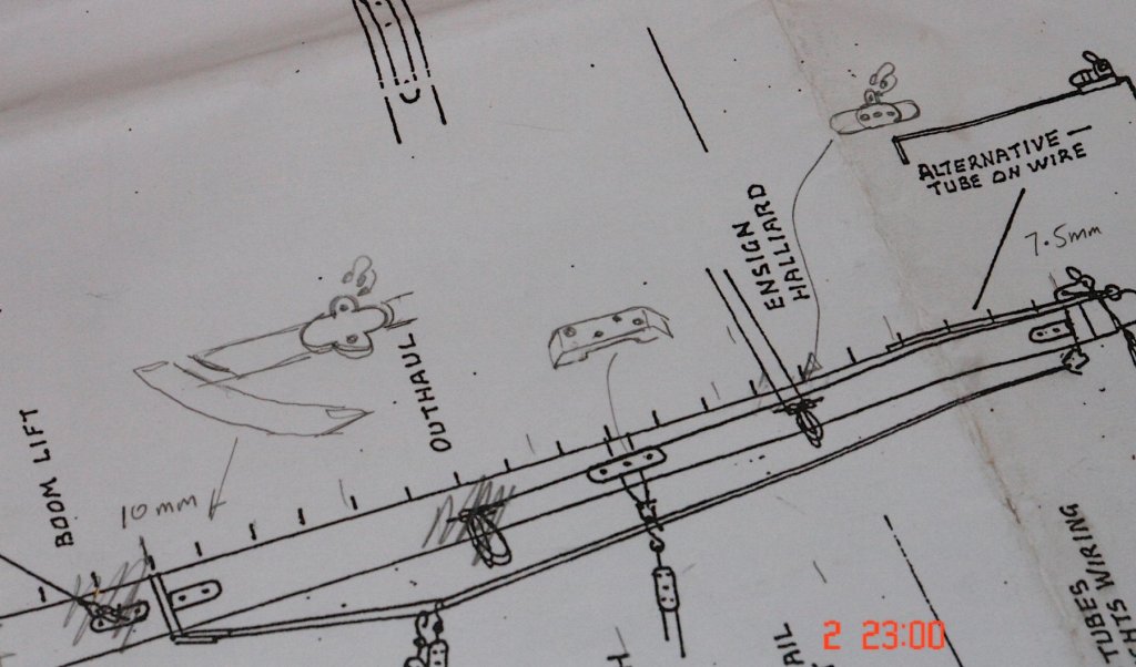 I started by turning down a .500" dowel to .400" and then tapering the last third down to .320". I left a section at the narrow end at the full .400" diameter to simplify location on the mill. I then spent a lot of time on the milling machine - drilling holes and machining slots at various places along its length.
 The long thin slots are to take the rubbing strips. They are .040" wide by 4.5 inches long and .030" deep. They were machined carefully with a very fine end mill - I broke one which was better than I expected.
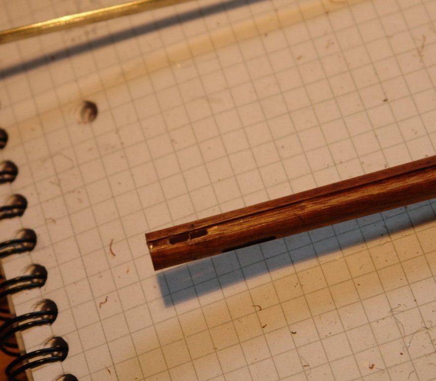
I gave making the track some thought and after a hunt in the shed came back with the "track" I had been looking for (Hornby OO).
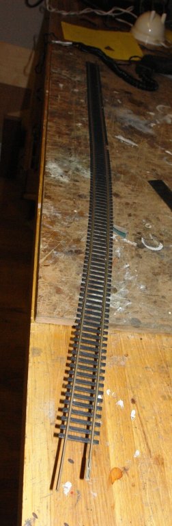
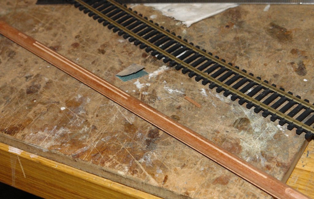 I machined a slot along the length of the boom (bottom of the boom in the image below)- .084" wide x .030 deep to match the rail bottom flange.
I extracted one rail from the track and did a trial fit - I think its going to turn out well as long as I can find a sensible way of making the sliders. Across 3 sails I need about 60 sliders which feels like a bit of a challenge. Anyway thats for the future as the next few days are devoted to a new deck for my daughters garden.
-
Hello JD
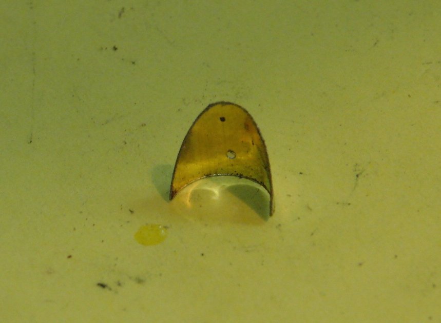
The holes were drilled through the strap, a dimple being made with a centre drill and then drilled through with a .028" twist drill. The holes were drilled using my milling machine - to avoid breakage of the drill. The holes were made to take pin heads which simulate the attachment rivets. The previous photos were of the part complete component, in the following images its a bit further on but still with the radar dome and horns to be attached. The images are some what magnified as can be seen from the size of the pin heads.
The protruding bit is a pin head. A hole was drilled in the centre of the oval and in the strap and a pin put in place to ensure alignment while soldering. I cut it out once soldered. Well spotted.
- archjofo, Julie Mo, michael mott and 4 others
-
7
-
-
-
Richard - the poly is Wilko Satin Finish Yacht Varnish. I'm not very good at spending more than I can get away with and I find the Wilko poly quite acceptable.
Bedford - I think I am going to let the brass mature with age. The yacht and myself will both fade away together!!!!
Thank you both for your comments and thanks to all those who have "liked" my work
-
Thanks Richard.
I started to feel that I could do better to mount the yards more securely and accurately. Rather than inserting the yards directly into the hole drilled in the wooden mast I decided to make a sleeve to insert in the hole. Making the sleeve a tight fit around the yard had the additional advantage of guaranteeing the correct angle.
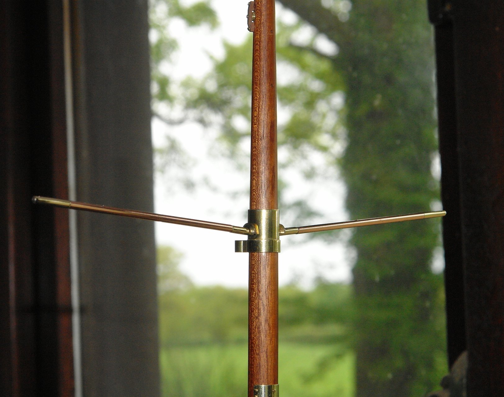
I continued to make mast fittings and attached the plates where the strops sit and where the gaff hoist pulley rubs against the mast above the yard.


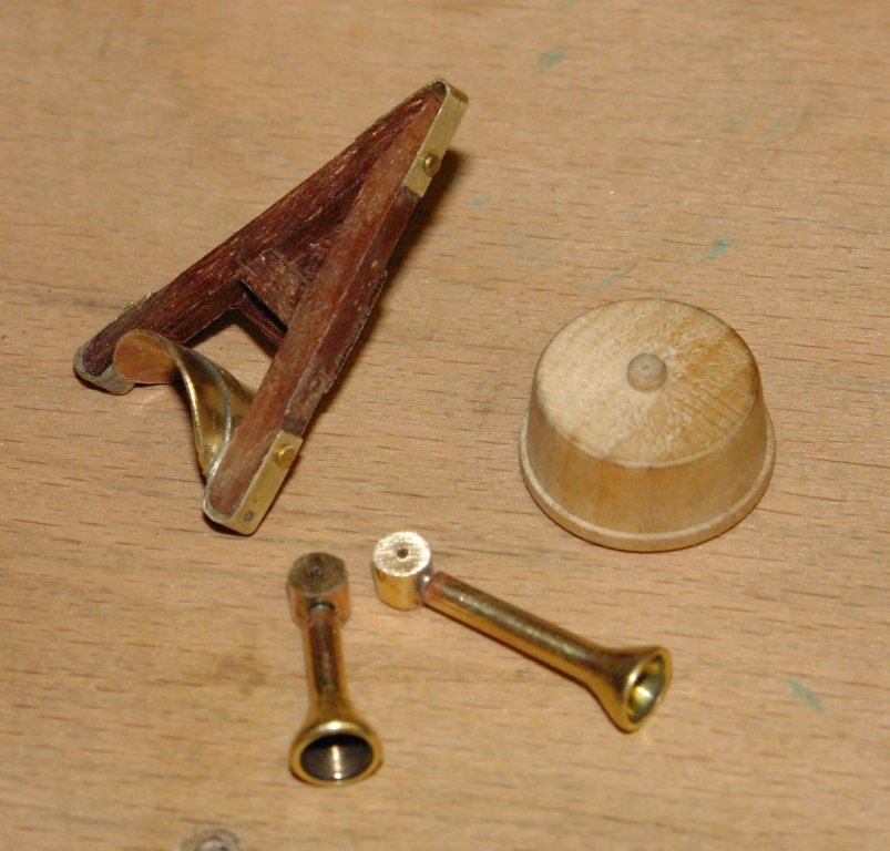
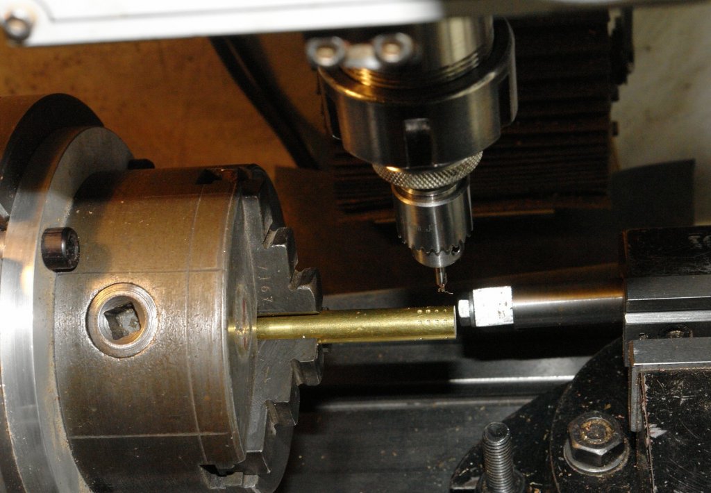
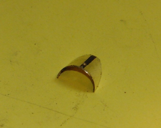
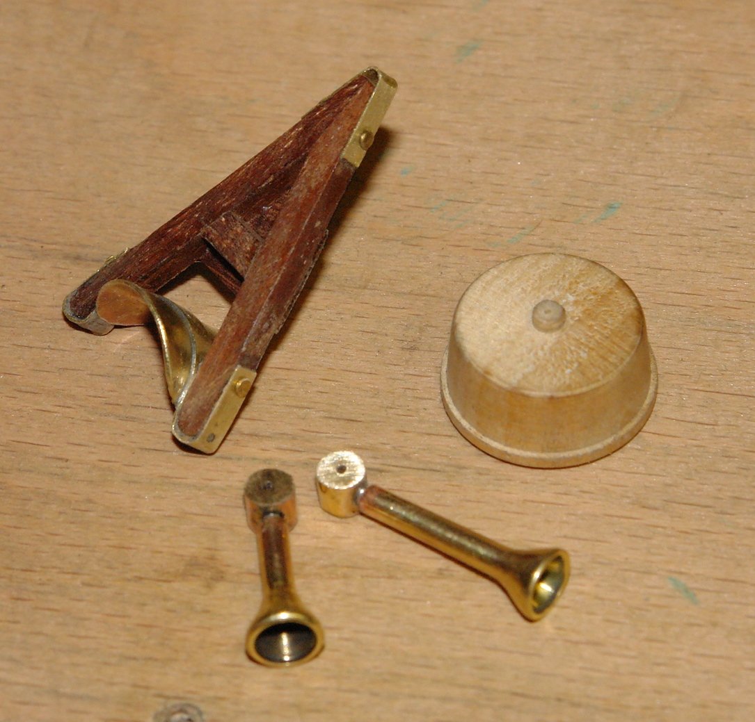
The radar sits on a tricky little "A" shaped frame just below the yard on the main mast. The tricky bit is the bracket which attaches to the mast. The bracket plate is a curved oval (about 0.6" x .5"). I stuck a paper template on a tube and cut this out with a jewellers saw and finished it with a file.

The plate attaches to the wooden "A" frame via a strap - I cut this strap on the lathe - its 0.1" wide.

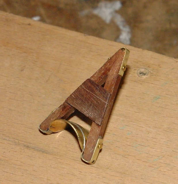
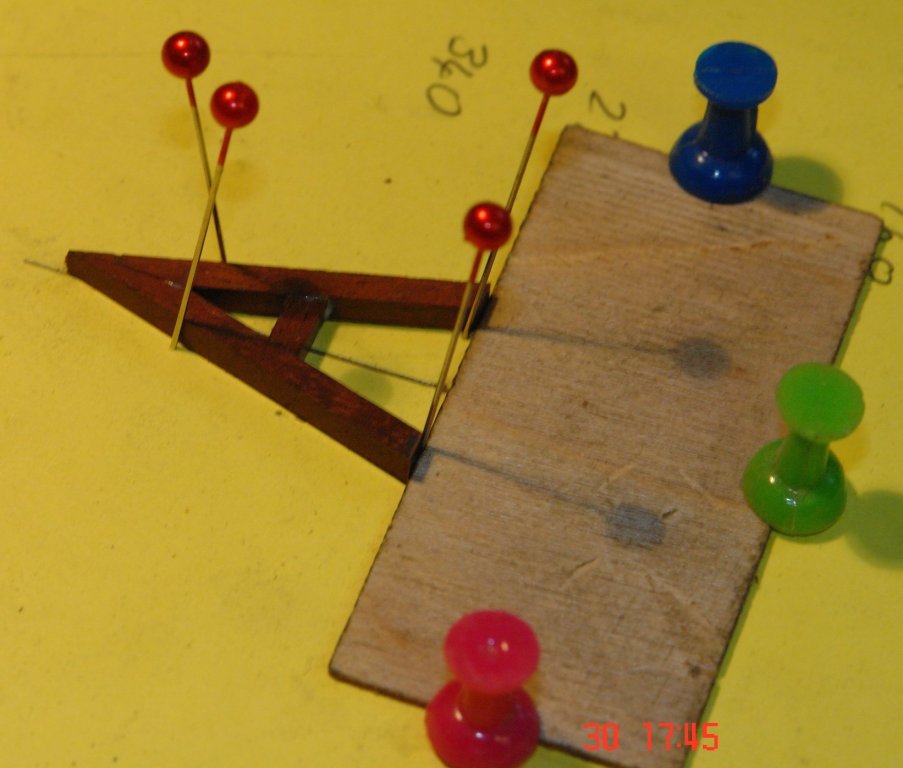
The strap and the plate were soldered together. The set up for soldering uses two tube spacers (aluminium and copper) to pull the stap tightly against the plate. The aluminium was used because it wouldn't accidentally solder to the bracket. The first photo shows pre soldering with the solder wire balanced in place. The second photo is post soldering and the third photo shows after clean up using a brass brush wheel. I used a torch to do the soldering.


The "A" frame was made from 0.1" square mahogany.
The strap was then bent to shape and attached to the "A" using CA glue.
I now need paint the frame with poly and make the radar and horns which attach to the frame.
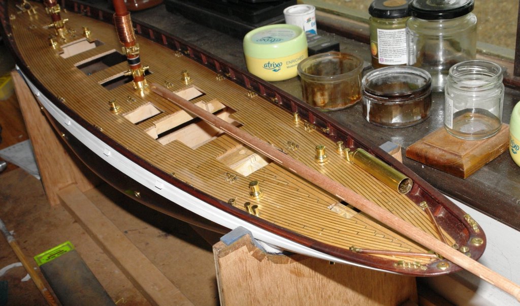
I had the Yacht on the floor so I took a photo.

-
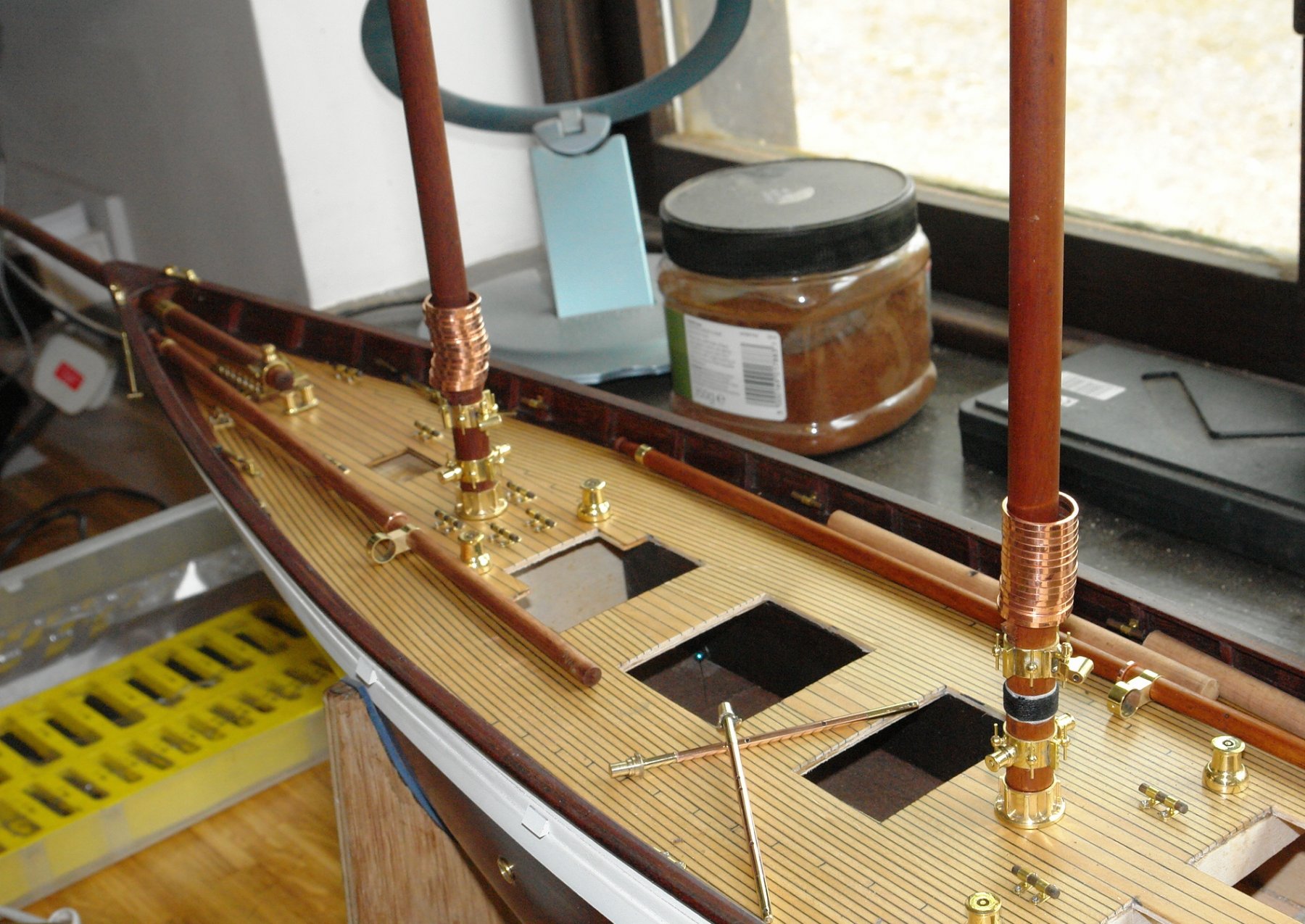
A little more progress:-
The foremast caught up with the main as far as fitting out was concerned.
 At the head of each mast is a pair of pulleys. The body measures .32" x .08" x .08", the pulley is .160" diameter by .04" thick. The body was milled to shape.

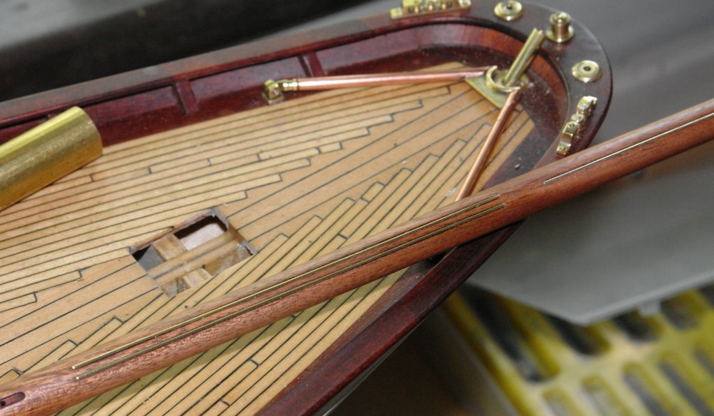
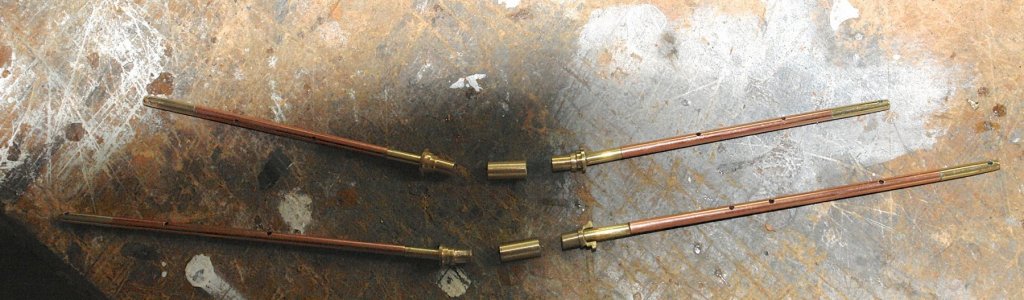
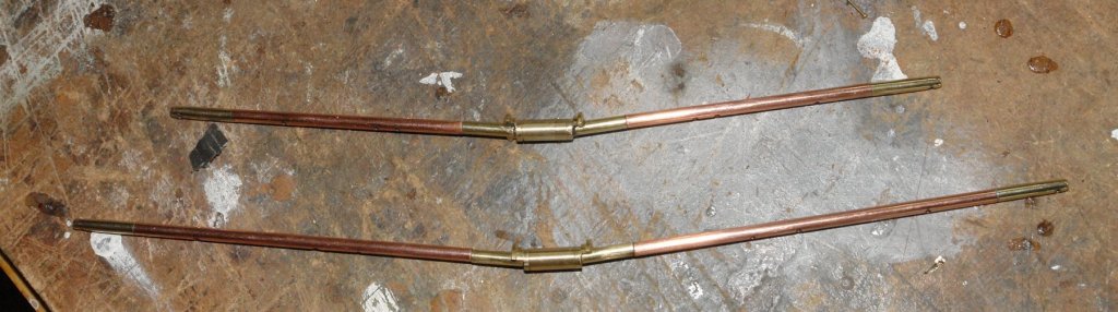
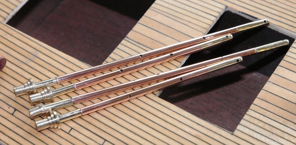
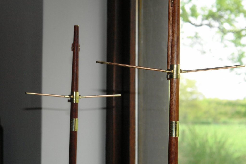
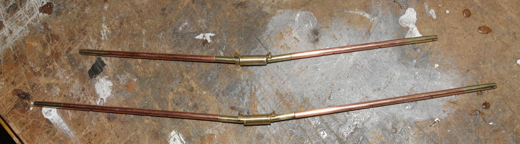
I made the yards from mahogany but at a little over 1/8 inch diameter they were quite delicate and flexible. After scratching my head for a while as to how to make them robust I went back to web photos and realised that on Altair the yards are actually made from metal - painted white. The problem of flexibility was therefore resolved with the yards made form copper tube with brass end fittings. I'll decide later whether or not to paint them. I still need to make the lights, GPS receiver etc which attach to the yards.

I then went back to more mast protection plates of various shapes.
I had a bit of fun working out the best way to make the oval ones for the shroud strops.

Thats all for now folks.


- Julie Mo, Nirvana, michael mott and 8 others
-
11
-
Nils
I do think the side view with the davits in place makes the ship come alive - love it.
- Martin W, Piet, Mirabell61 and 4 others
-
7
-
-
Richard,
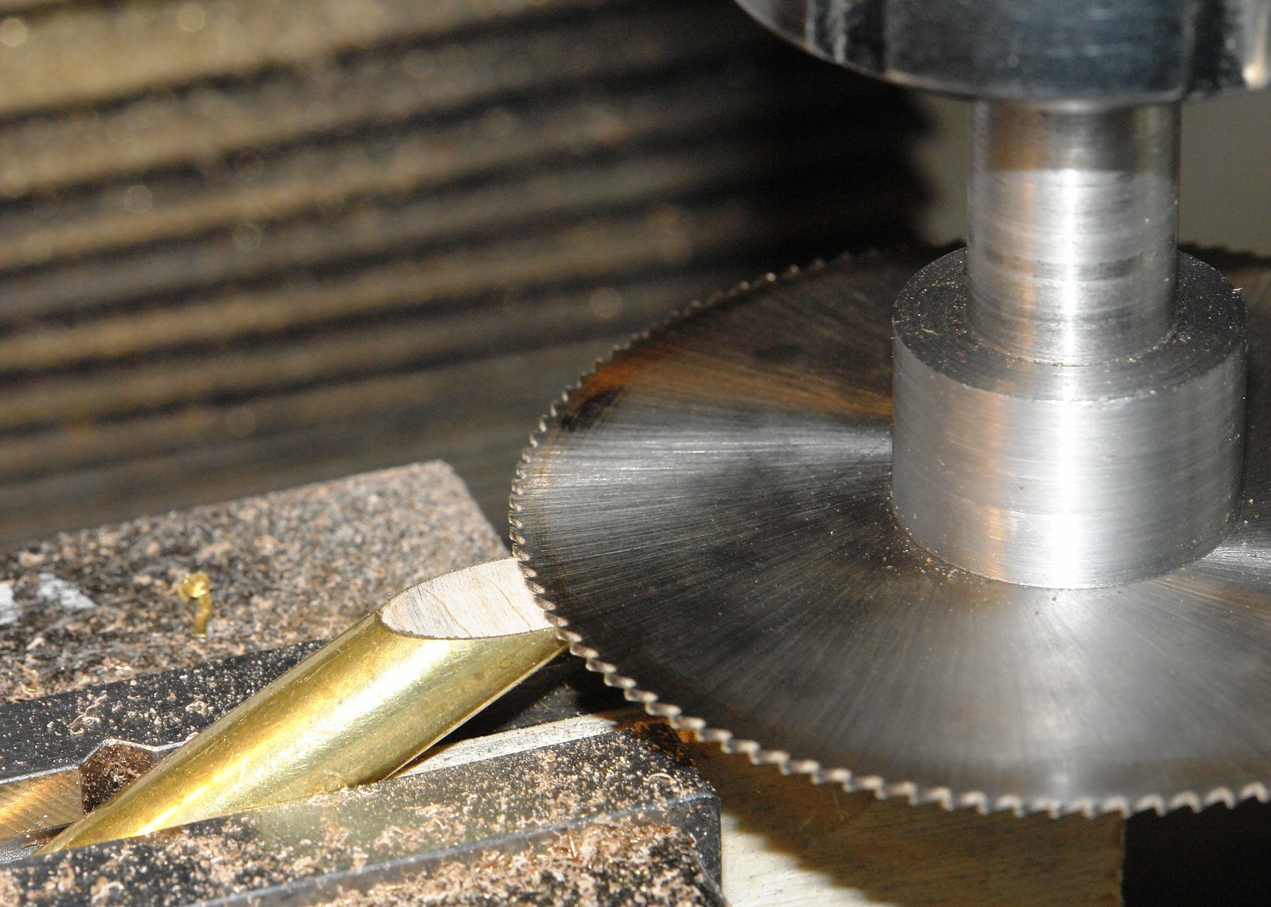
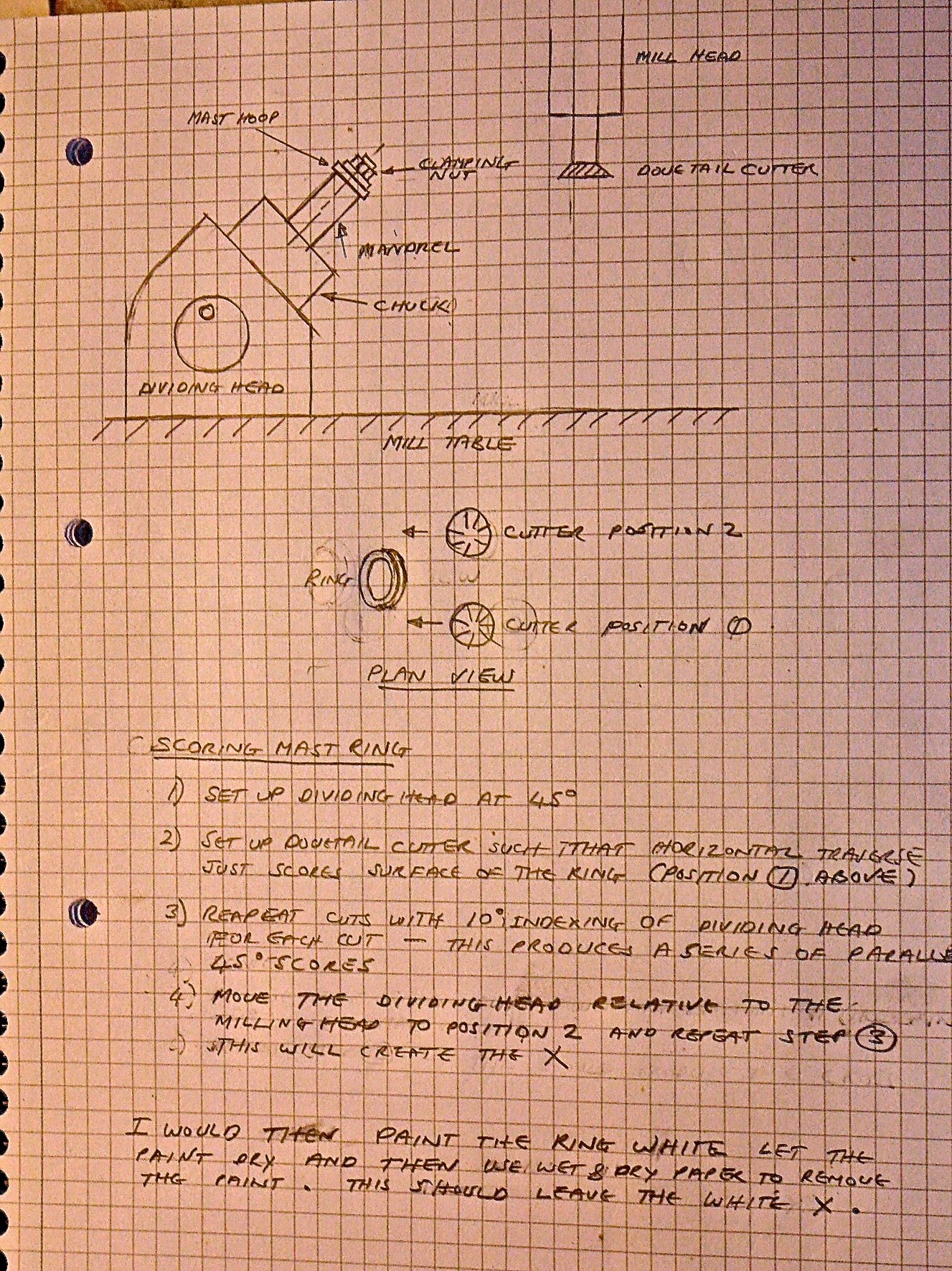
I was also thinking along the lines of a knurling tool as an option. I don't think you would get knurl wheels off the shelf but it is possible to make your own. The problem I'm not sure how to resolve is how to get the register right between the forward and rearward sloping cuts. It sort of needs the knurl wheels connected through a gear.
-
Michael - I have had problems in the past bolting directly on to perspex. After a while I noticed small cracks starting to grow from the bolt holes. I cured it by using rubber grommets to line the holes (slightly wider than the perspex thickness). It may be that I had a bad experience and you will get away with it.
Excellent work as always.
- cog, popeye the sailor, Omega1234 and 3 others
-
6
-
-
-


Vanity by M.R.Field - scale 1:16 - RADIO - Victorian Racing Cutter
in - Build logs for subjects built 1901 - Present Day
Posted
Martin
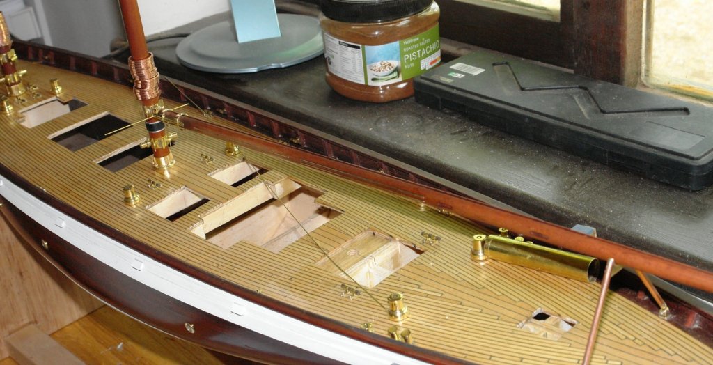
Venetian blind slats seem a little expensive at 50p. I found mine in a bin.
They do however make nice deck planks as per attached photo.
You should do well given all your model making experience.