HOLIDAY DONATION DRIVE - SUPPORT MSW - DO YOUR PART TO KEEP THIS GREAT FORUM GOING! (Only 44 donations so far out of 49,000 members - C'mon guys!)
×


KeithAug
-
Posts
3,957 -
Joined
-
Last visited
Content Type
Profiles
Forums
Gallery
Events
Everything posted by KeithAug
-
 Ah! I thought it had the look of a "Percy".
 -
Michael is it based on an actual engine? Nice work on the interior - I will be interested to find out what the end game looks like.
-
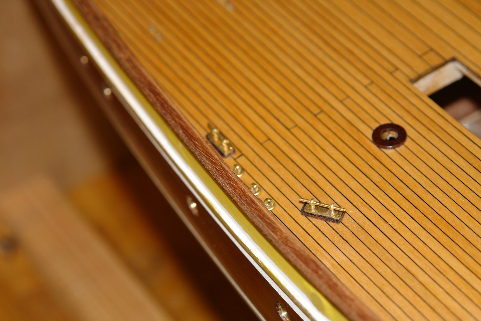
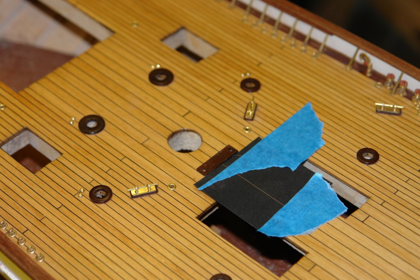
Thank you John. Not a lot of progress but I have glued on the stern rail and given all the rail 4 coats of poly. Painting does slow things down. I was thinking that the next task would be making the shock absorbers for the main sheet and the fore sheet - 3 in total. At scale size they are about 0.8 inches long - so a lot of detail in a small space. I made a start by making, painting and installing the 2 deck plinths (the stern shock absorber sits directly on the rail without a plinth. The stern rail was then attached with PVA glue and sanded to blend. It was then on with the poly - the 4th coat is currently drying.
-
Dan = excellent, but I am sorry to see the journey end, the sea looks perfect. I look forward to the next project.
- 238 replies
-
- 3
-

-
- leviathan
- troop ship
- (and 2 more)
-
Yes - and with each couple of years that pass you will need another 50% increase and yet another expensive upgrade from the optician. The good news however is that you stop seeing the imperfections (at least until you see the photographs). The shackles look pretty good to me - well done.
-
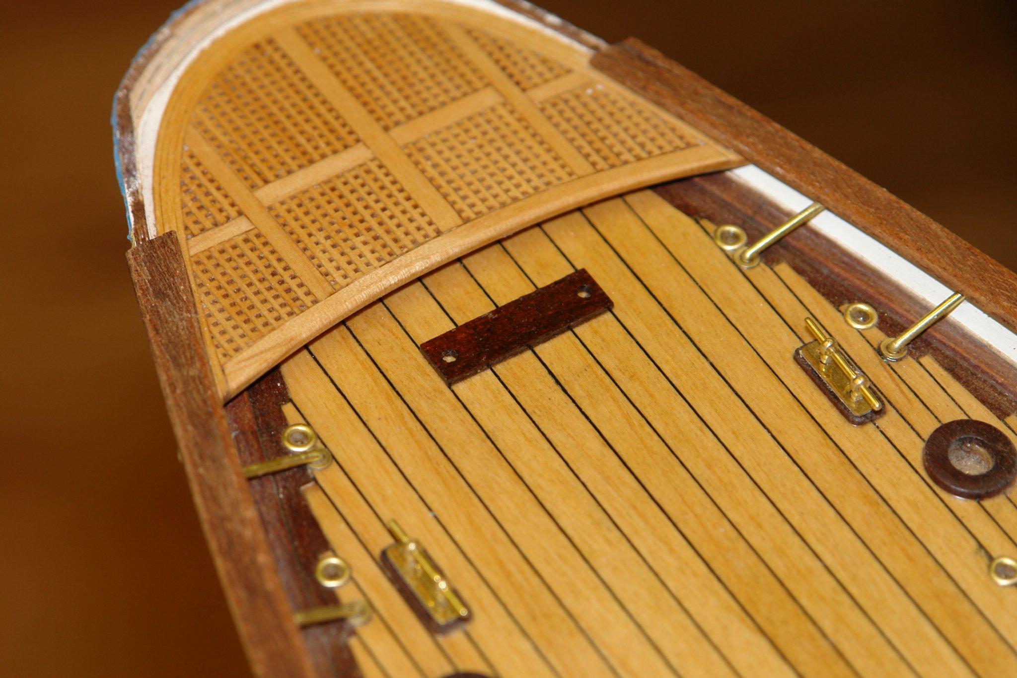
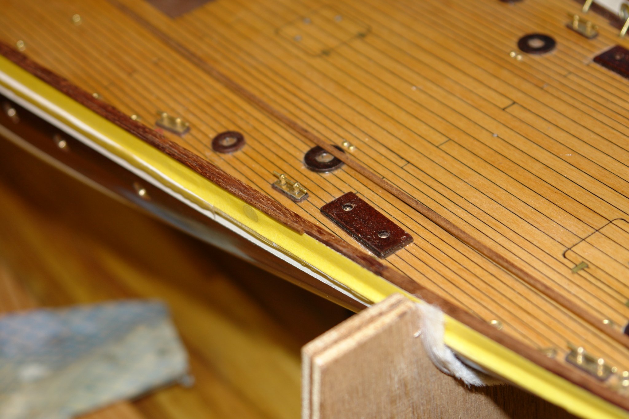
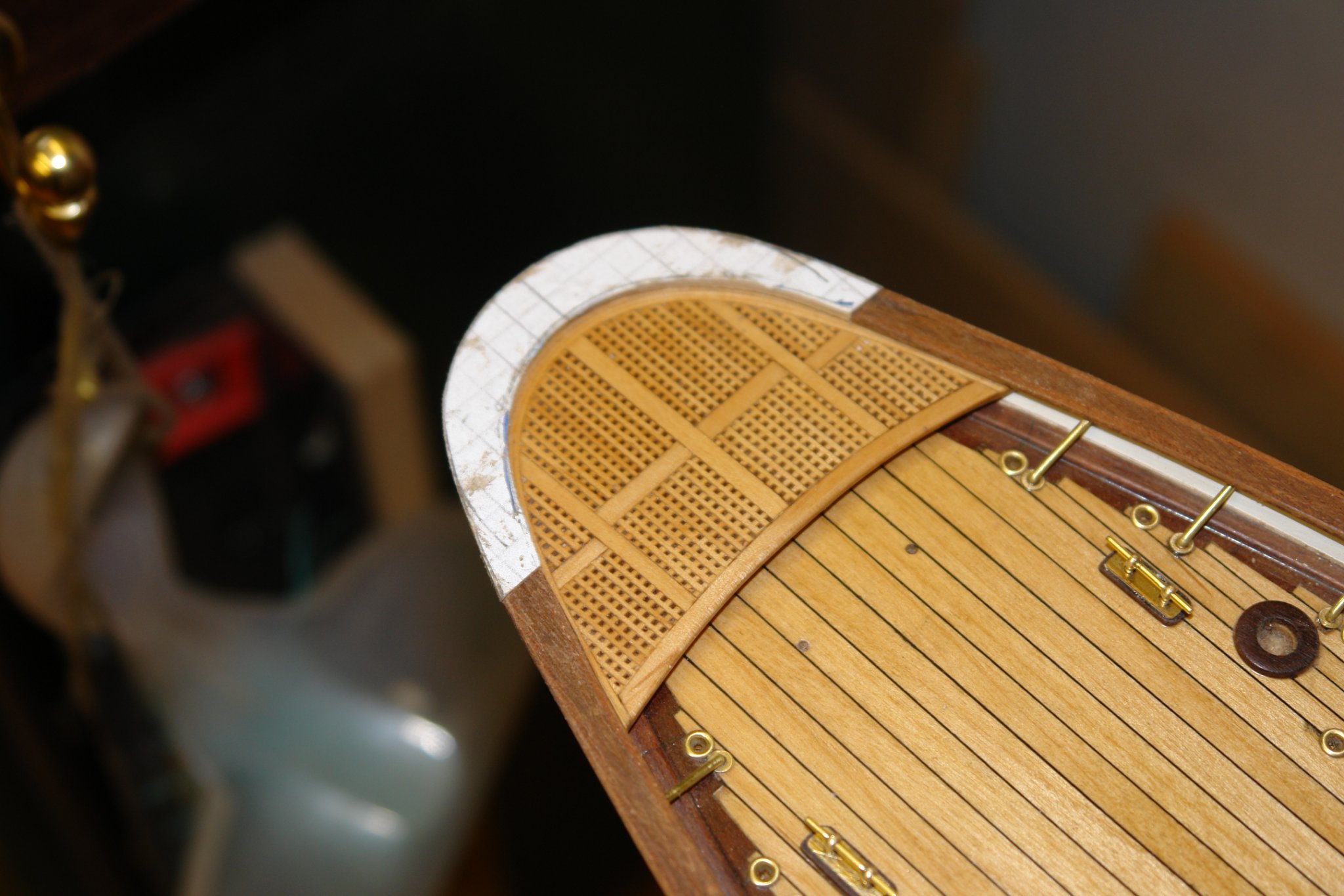
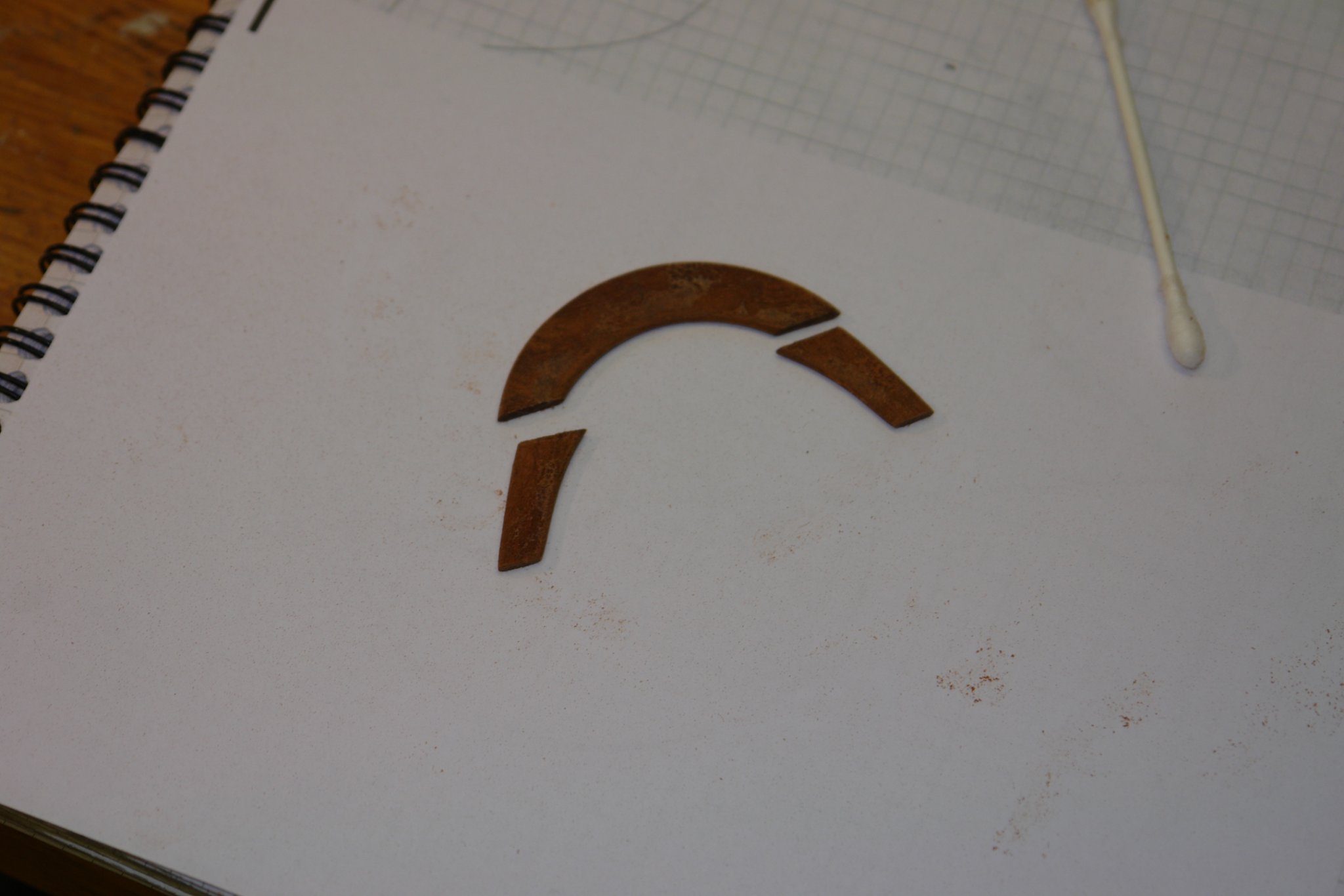
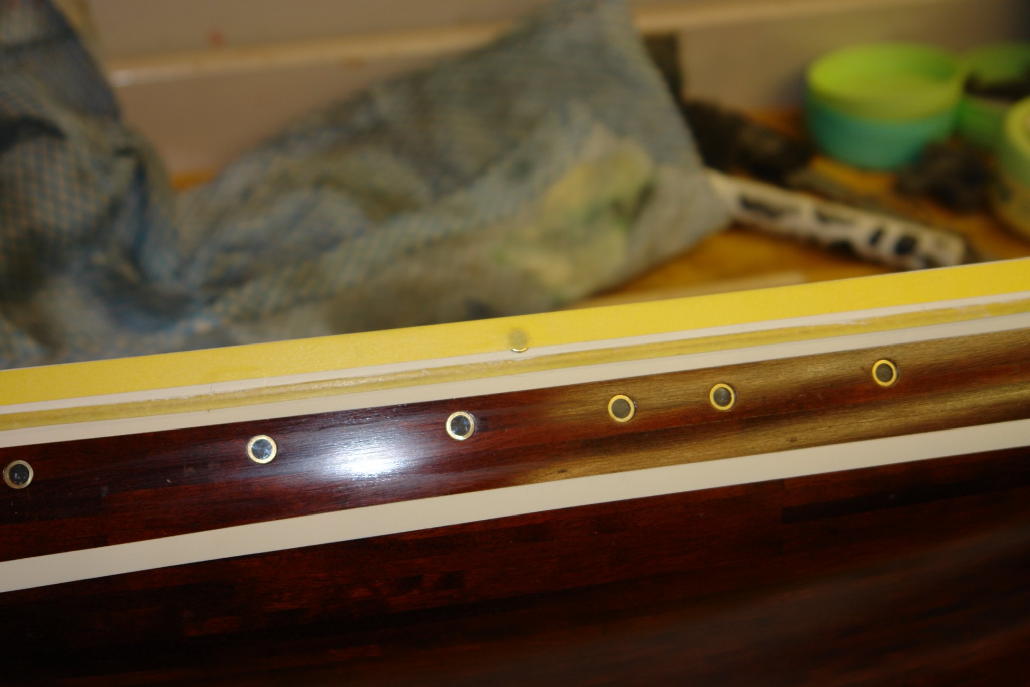
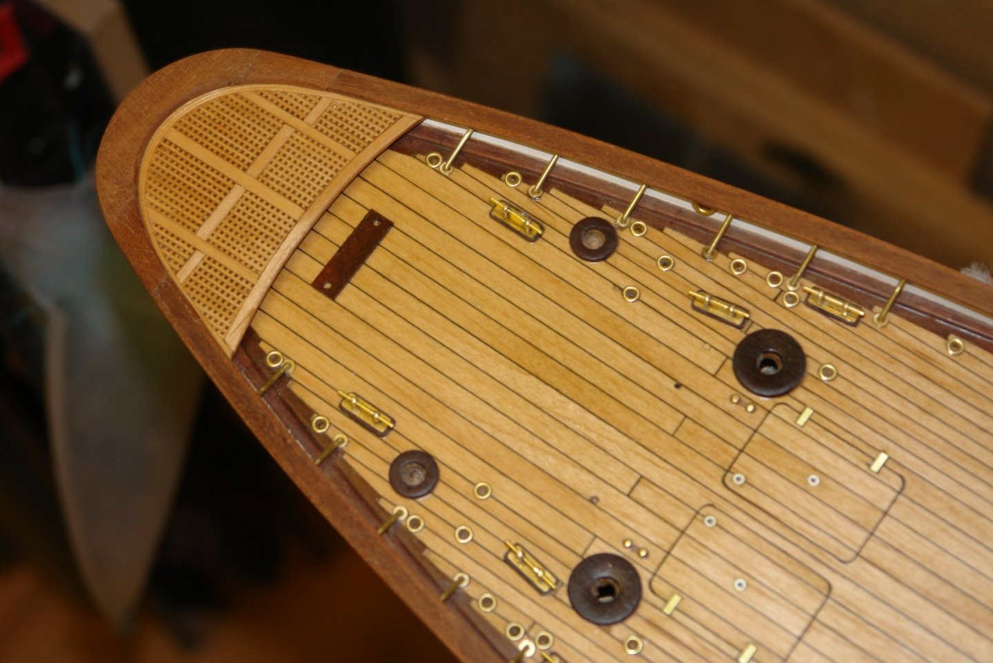
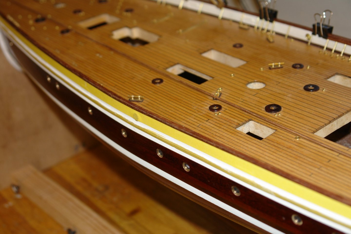
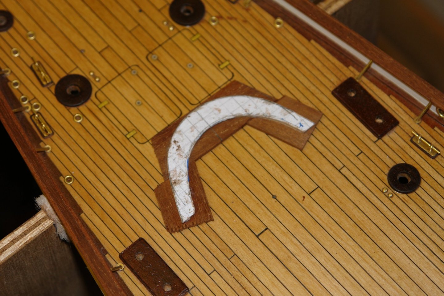
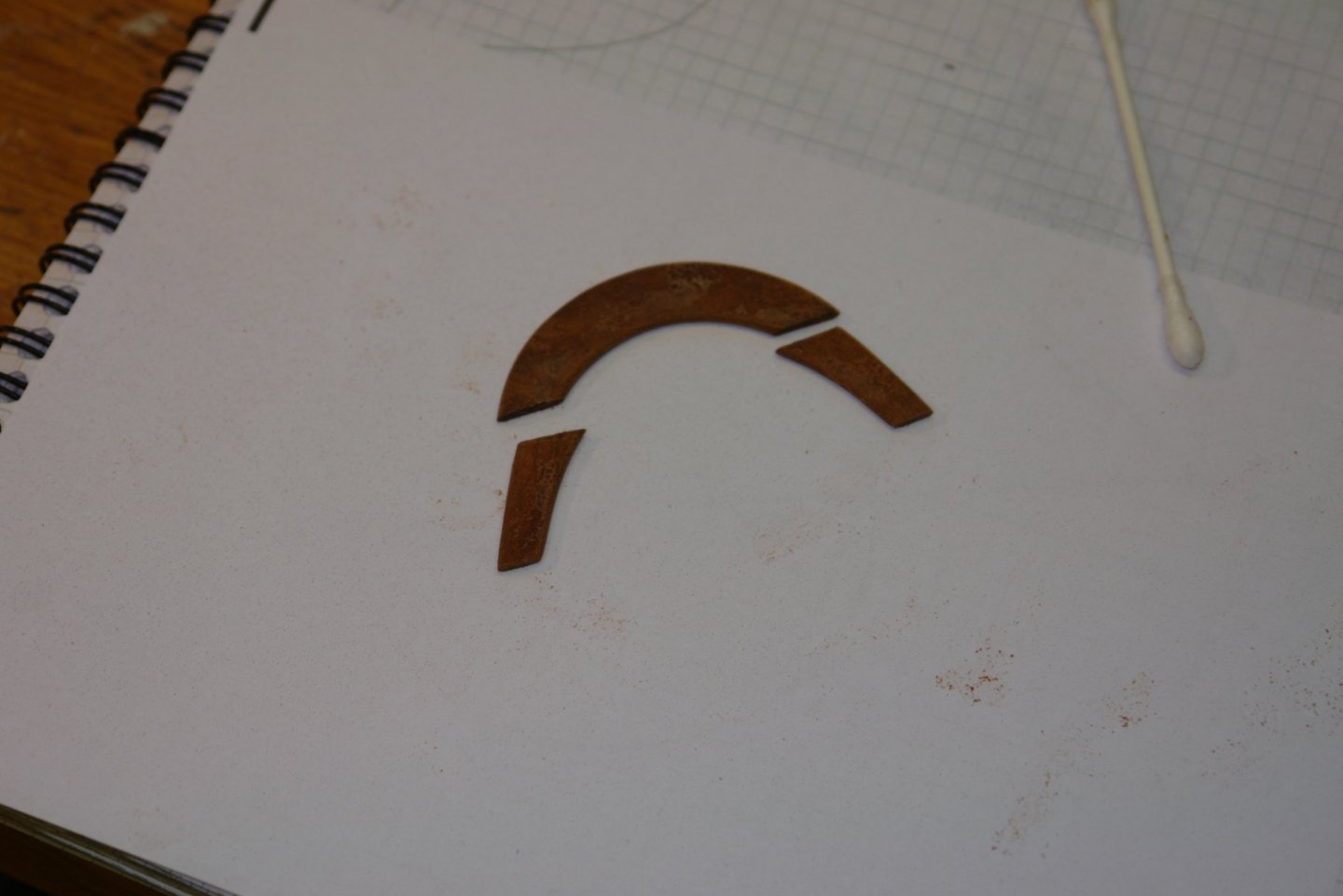
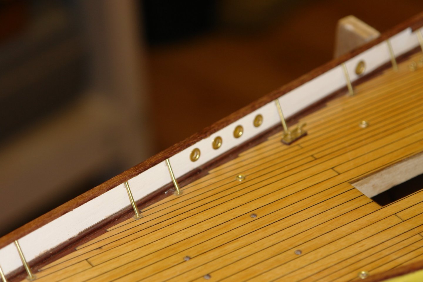
Thankyou all who have visited my build. I got on with finishing the cap rails. The next step was to make and attach the inner and outer "D" section planks items 2 & 3 in the photo. I started by cutting a thin plank 3/4" wide by .075" thick. As before the length was about 8 inches short of the hull length necessitating attachment of an extension piece. The "D" profiles were shaped on the edge of the 3/4" plank using a scraper ground from a box cutter blade and then the edge was cut off .0625" wide. I repeated this 5 times to get enough length for the 4 rail edges plus the extension pieces. The edges were then attached to the previously installed central part of the rail using PVA wood glue, carefully applied with a fine brush. I did this in steps of about 8 inches. Once glued the "D" strips were held in place with various clothes pegs / bulldog clips. The next photo show the junction of the extension piece. All 4 edges were done following this process. A light sanding then blended out the edges between the 3 planks. I stopped the laminated approach to forming the rail about 2" from the stern. Here the curvature and the changing width of the rail necessitated a different approach. To finish the stern rail I started by making a paper template which was in turn was used to make a 3/16" plywood template. To this plywood template I attached .075" thick mahogany with a glue stick. The mahogany was then shaped and removed from the template in preparation for installation on the bulwark.


-
John / Pat - thank you for the advice, I followed up on your suggestions. Fortunately the stopper is really quite small at the scale size so any inaccuracies in interpretation wont be too noticeable. Druxey - good point - I have renamed it "Wife Keeper", the alternative of having her attend the cold workshop may have had the opposite effect.
-
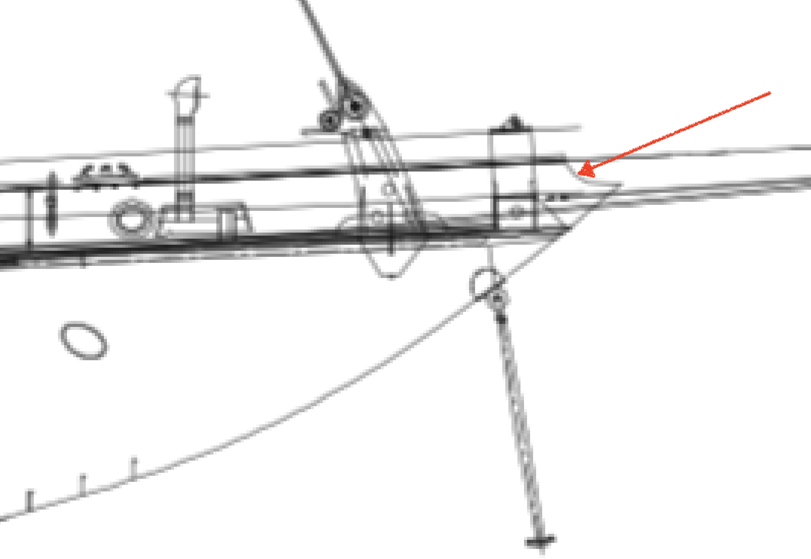
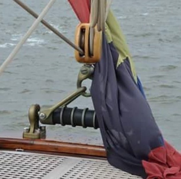
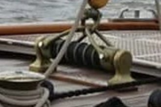
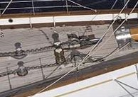
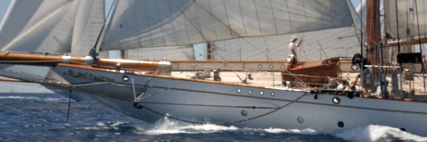
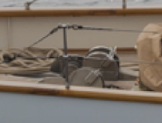
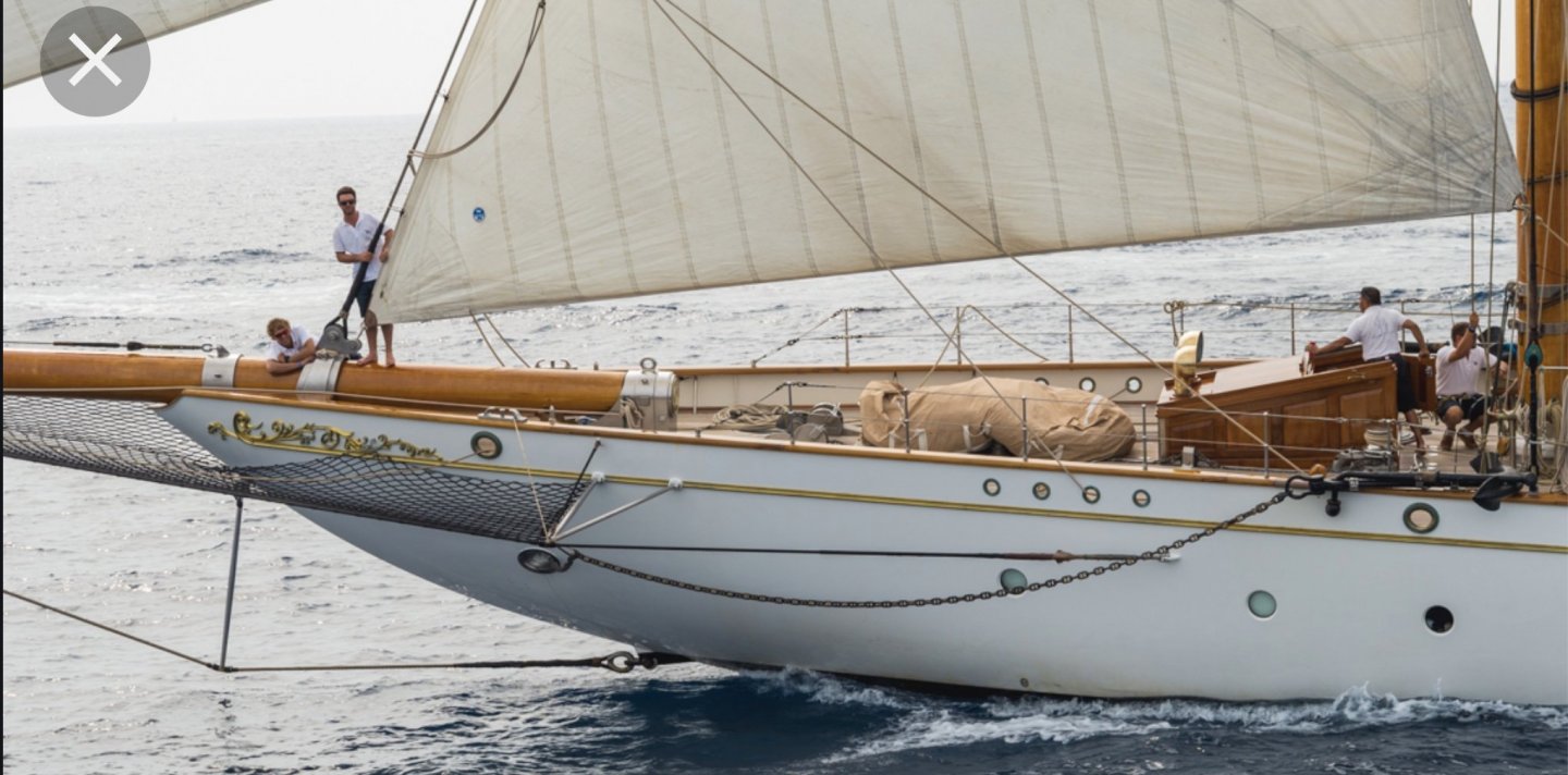
I am doing a bit of looking ahead. For a while I have been trying to get a bit more information on the chain brakes / guides that sit immediately aft of the hawse pipes. I have a few pictures but they don't make the design of the devices very clear.Each seems to consist of a pair of smaller hemispheical plates immediately behind which sits a larger pair. The latter pair seem to have a handle pointing rearwards at about 40 degrees. The anchor chain runs between the plates. My guess is that the smaller pair have a chain pulley between them. I have done an internet search but not found anything that looks like this, but I'm sure some of you may have some ideas??????
-
Pat - I usually think things through well ahead of doing them. The problem is that I often forget what I have thought of and create work as a result. I used to have a good memory but senility may be setting in. I ploughed on with the capping rail and finally arrived at the stern. About 8 inches of extension plank had to be added. I had worried about the difficulties somewhat before starting the cap rail but it proved to be fairly straightforward. I am reminded of Winston Churchills quote "I remember the story of an old man who said on his deathbed that he had had a lot of trouble in his life, most of which never happened". The rail is now ready to receive the inner and outer "D" shaped side pieces.
-
John - Yes the news is full of it here - it sounds pretty horrific. Wishing everyone a safe New Year.
-
HMCSS Victoria 1855 by BANYAN - 1:72
KeithAug replied to BANYAN's topic in - Build logs for subjects built 1851 - 1900
Interesting approach to the skylights Pat. Like others I think you are being a little hard on yourself, they look pretty good to me.- 1,006 replies
-
- 5
-
-
- gun dispatch vessel
- victoria
- (and 2 more)
-
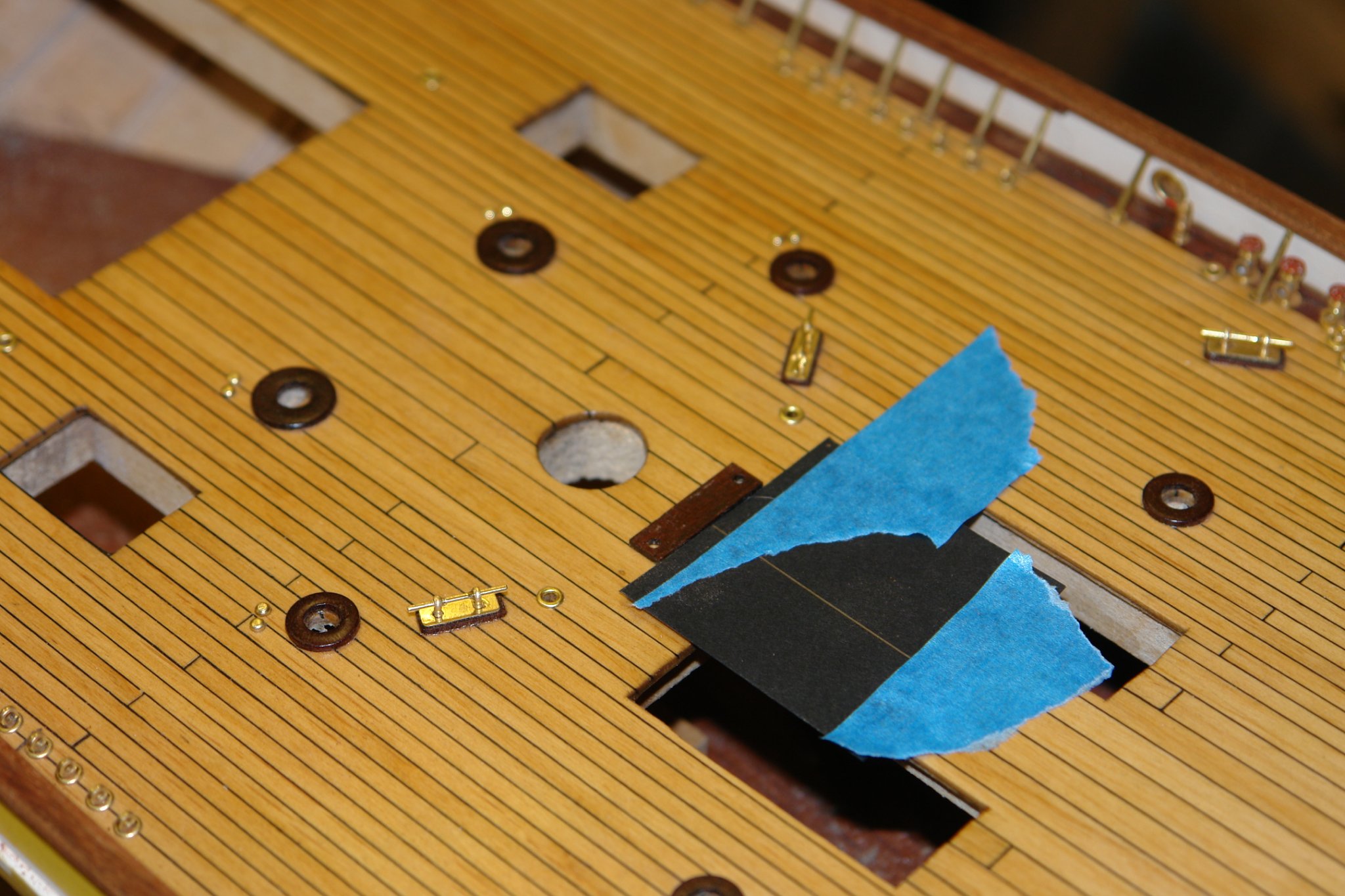
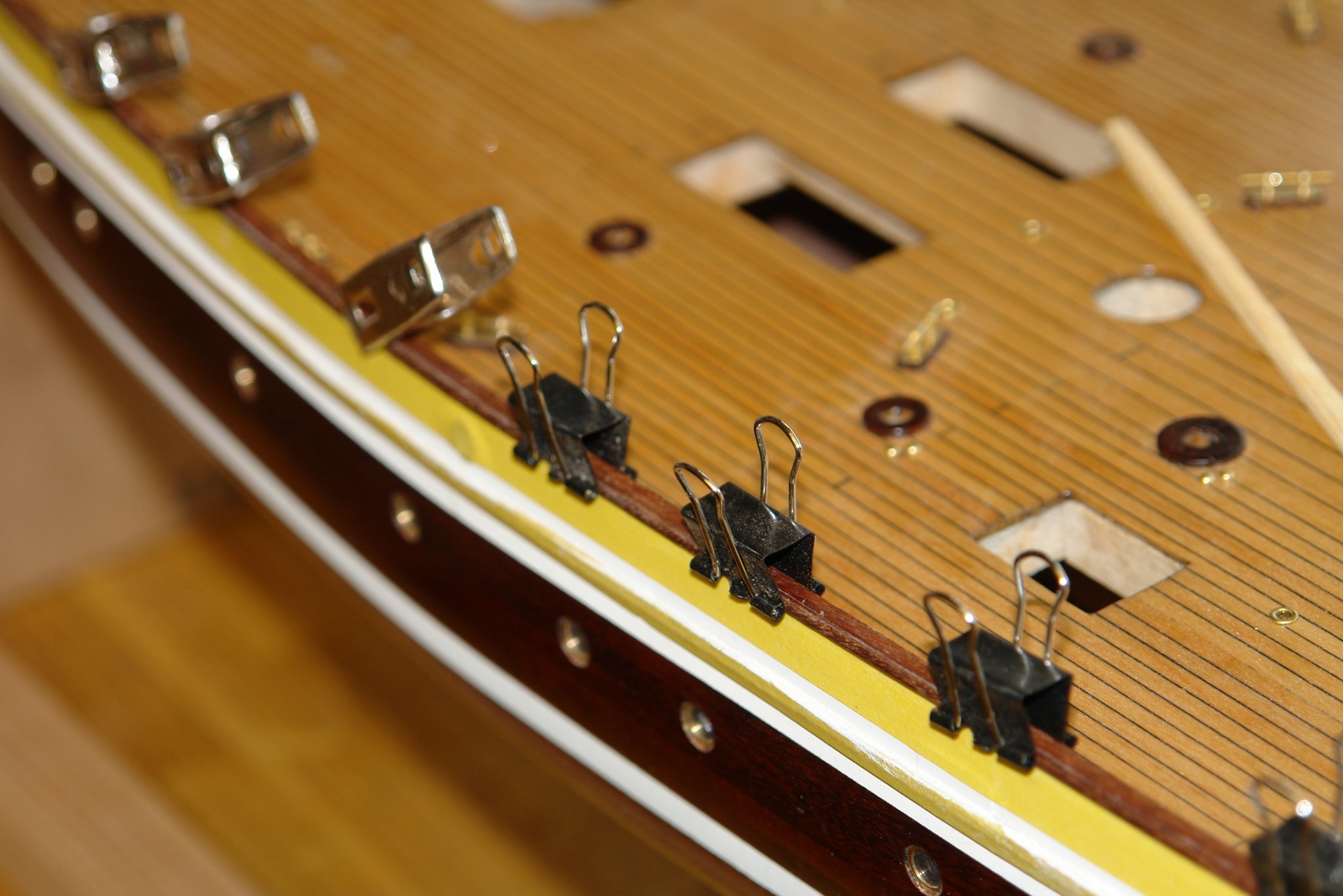
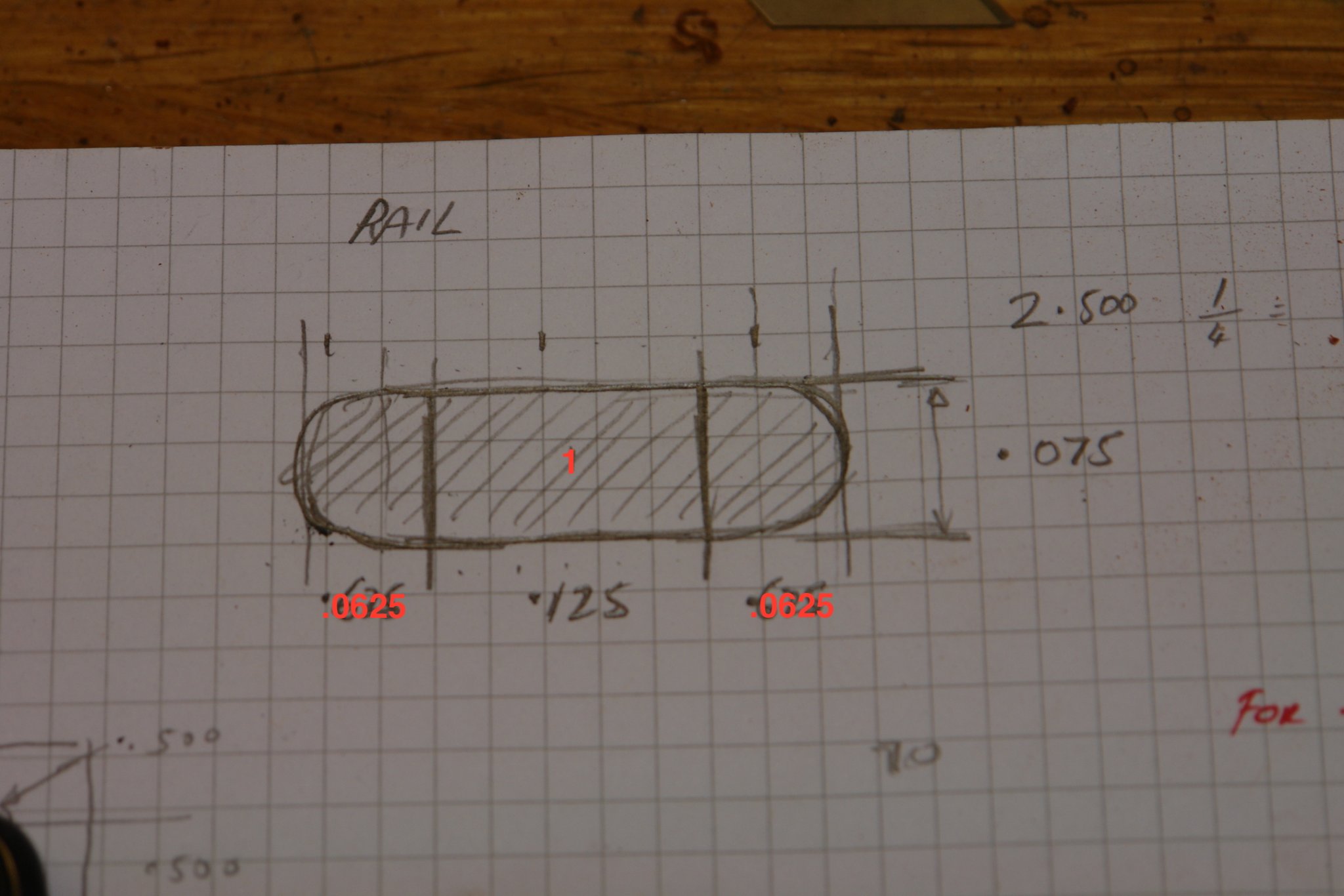
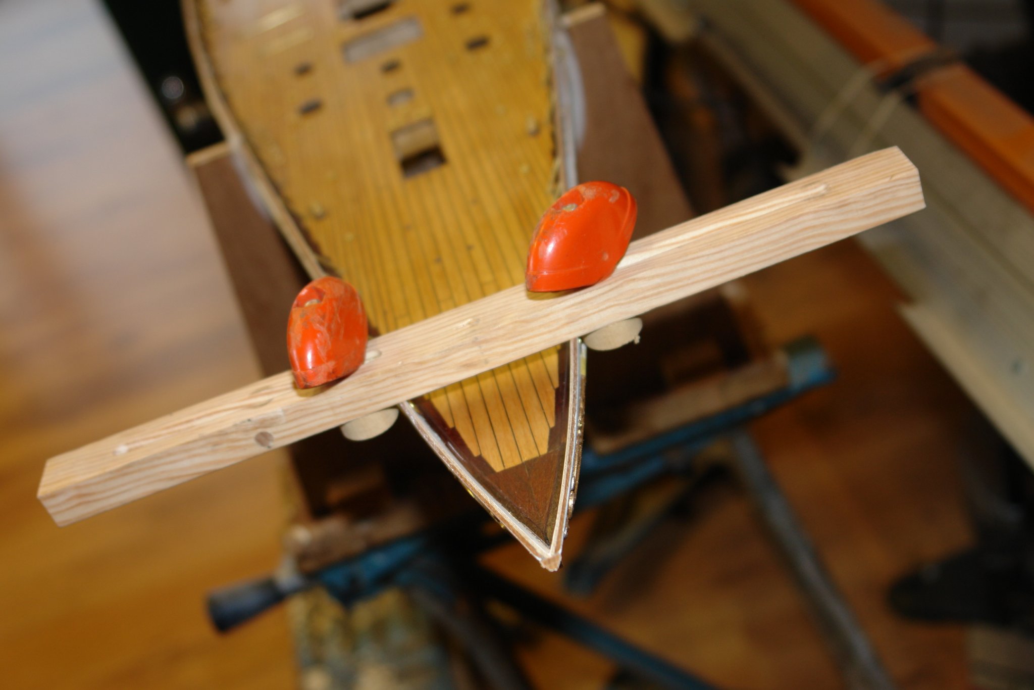
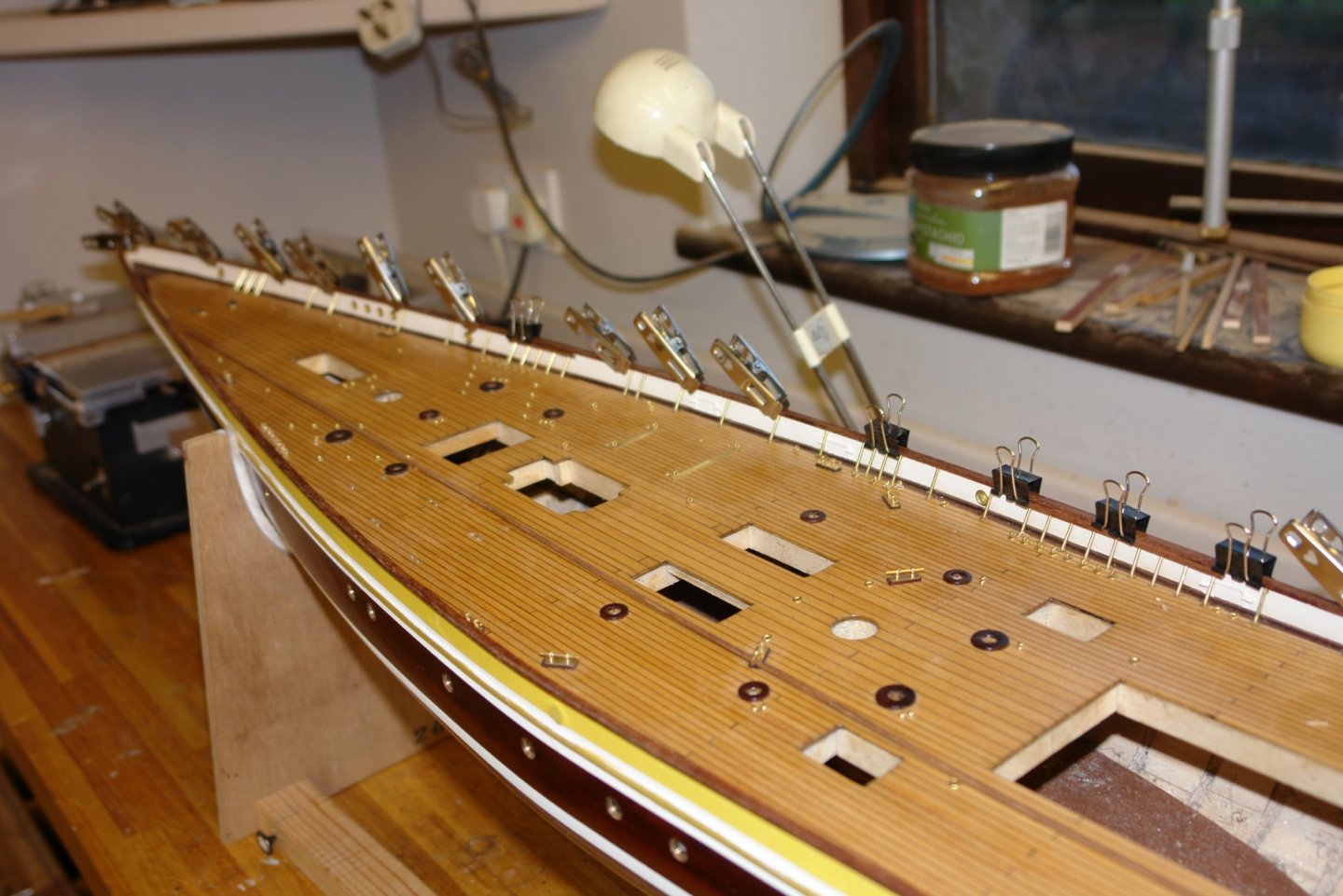
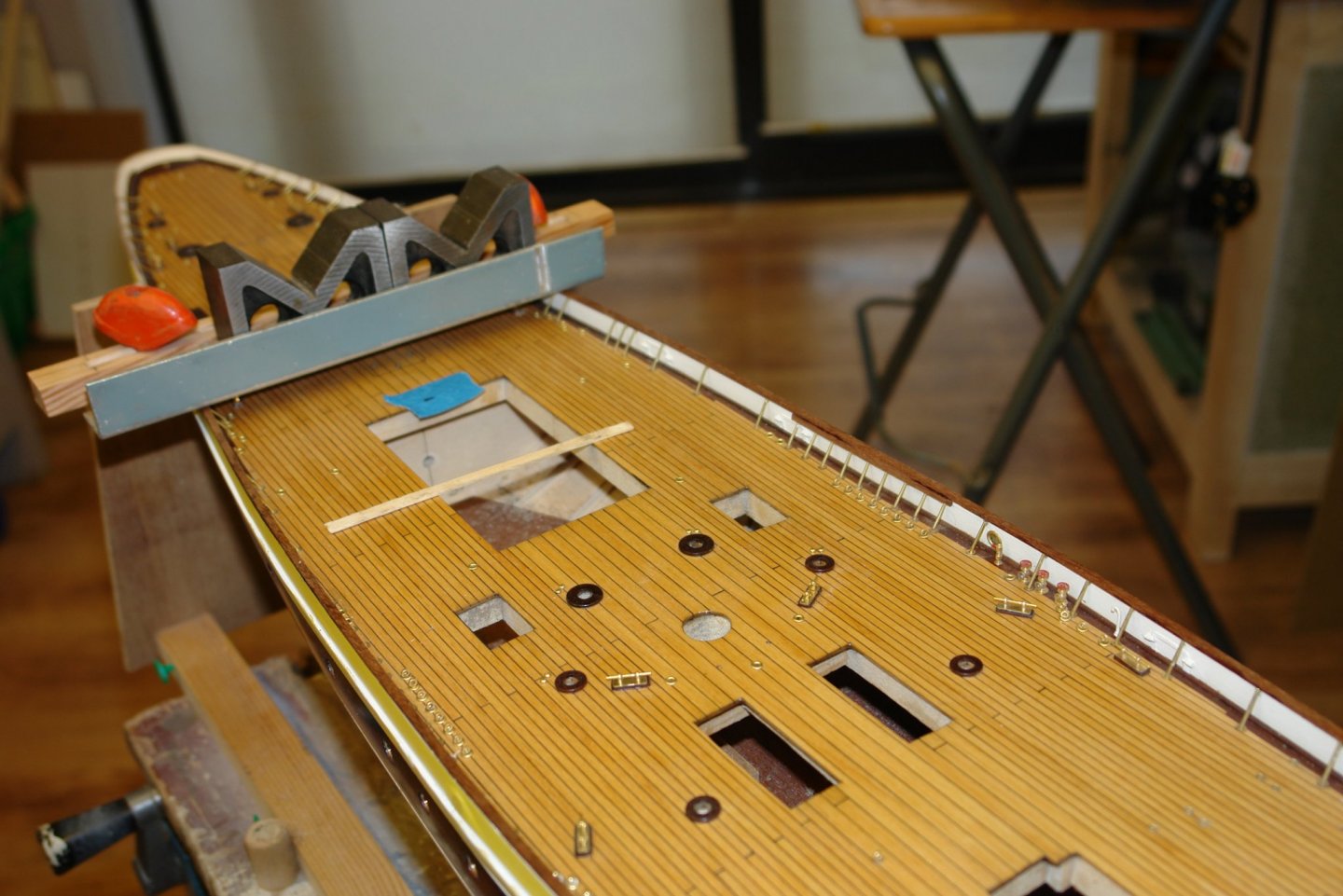
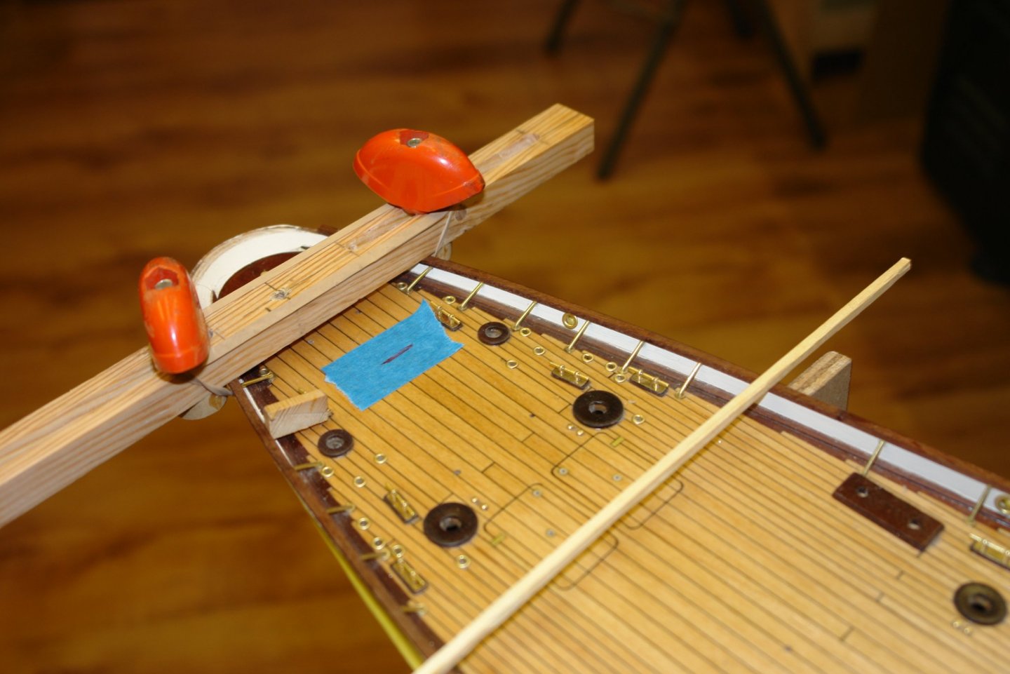
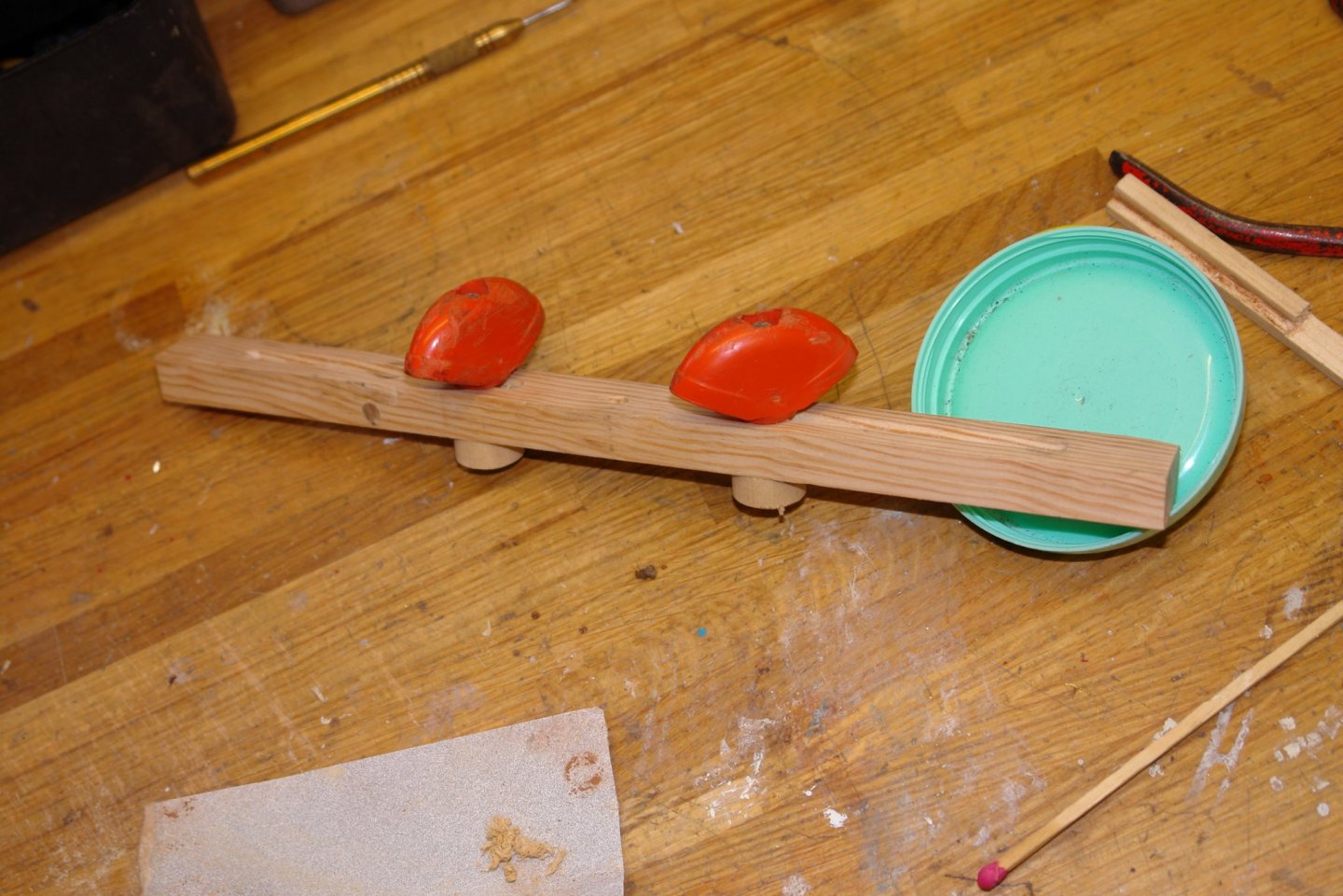
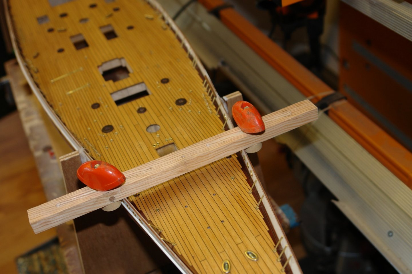
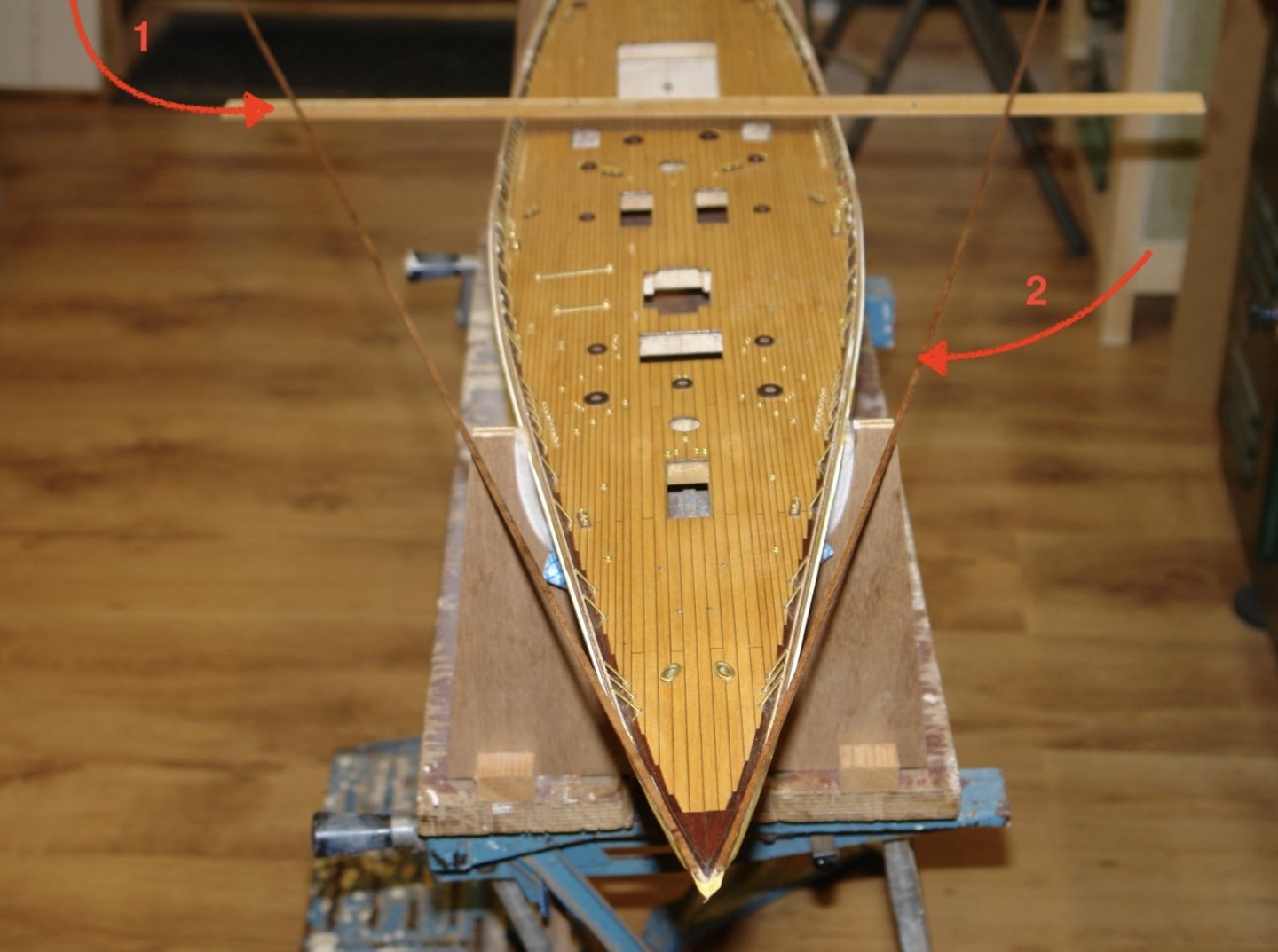
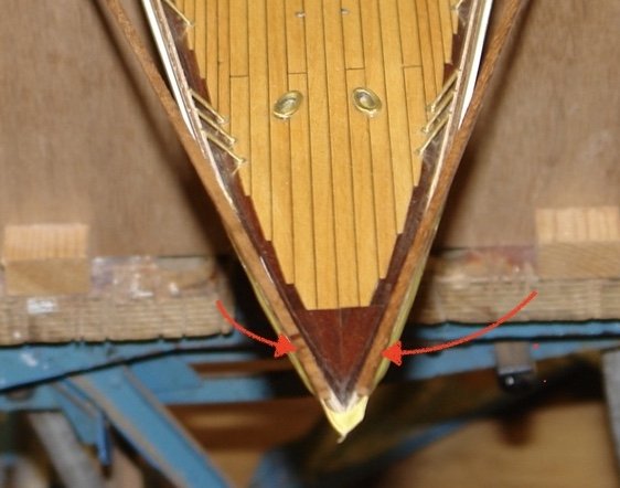
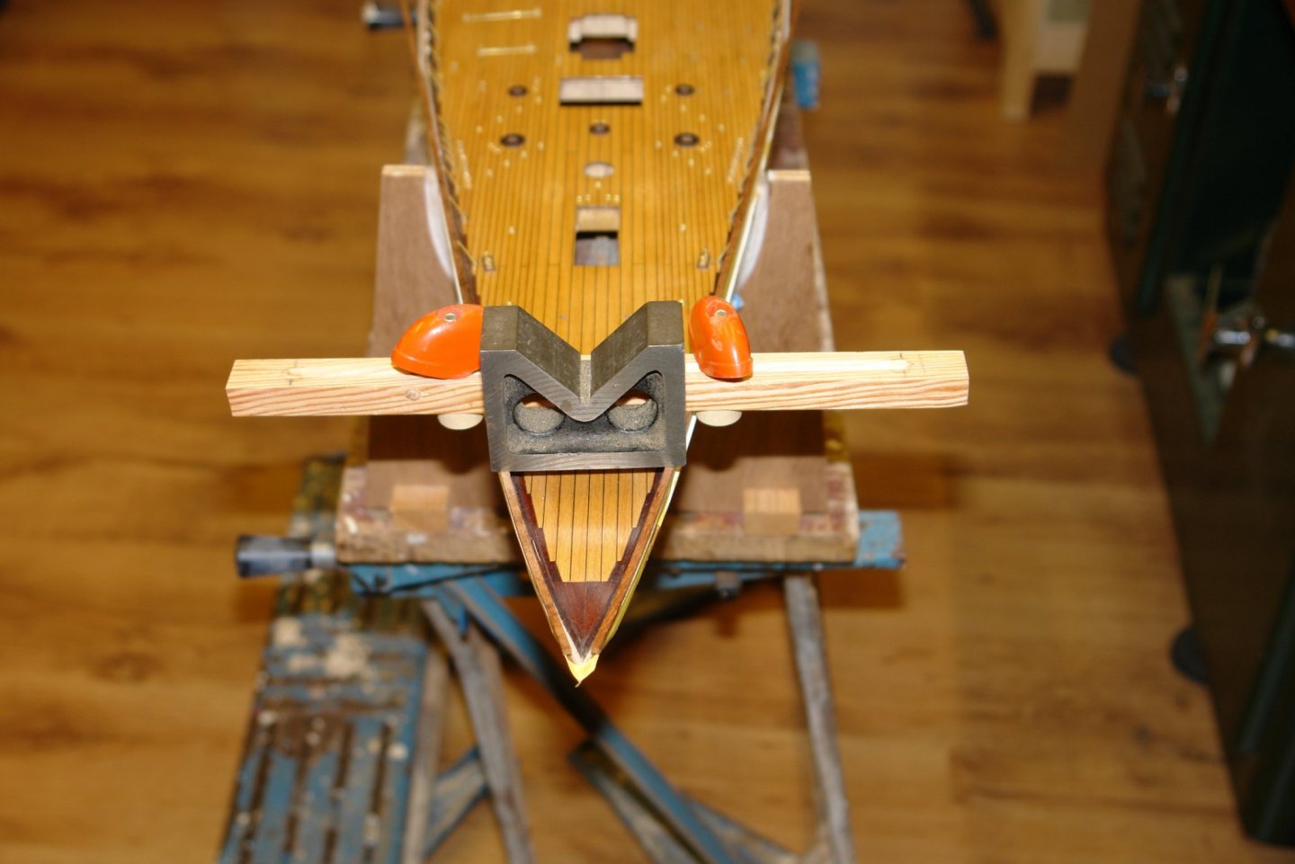
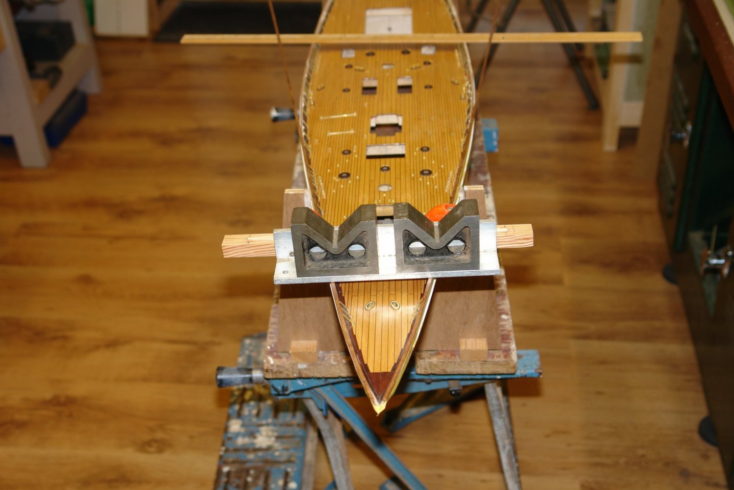
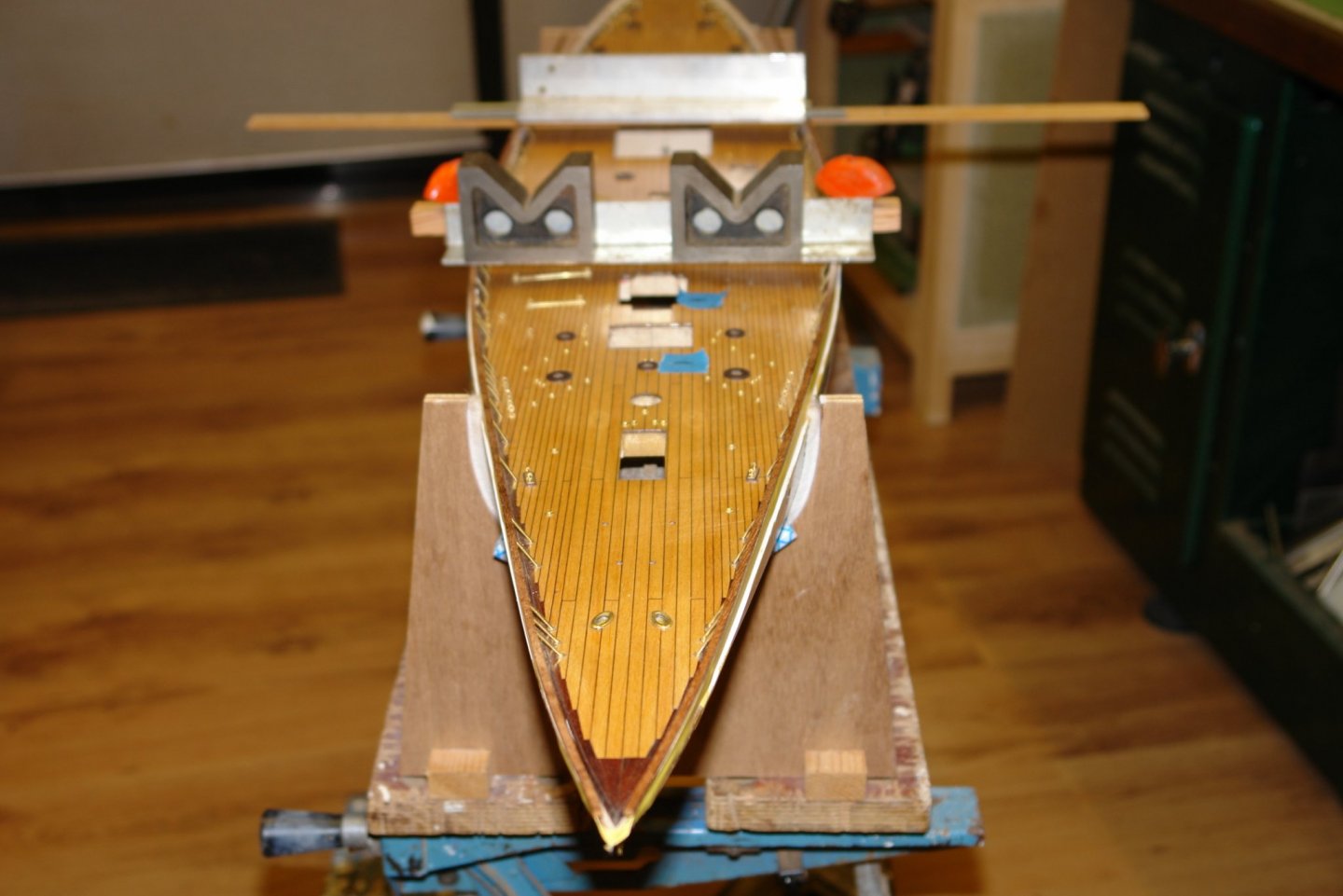
The shipyard has reopened after the Christmas and New Year break. Happy New Year to you all. Bedford, John, Michael, Gary, Caf - thank you for taking the time to comment and thanks to everyone else who has visited and liked my work. Pat - I have made a start on the cap rails. I decided to try and construct the rails on top of the bulwarks. The bulwark thickness is a little less than 0.1". Sizing the rail from photographs gave me a scale rail of the dimensions in the next sketch. Because of the considerable fore to aft curvature of the bulwarks I decided that I needed to laminate the rail in 3 pieces. Piece 1 of .125" x .075" cross section will be the first to go on. I cut this piece on the circular saw but unfortunately didn't have a long enough plank to get the full length of the rail, so it will have to go on as 2 pieces. I sanded off the edge of the bulwark to give a good surface for glueing. I pondered the problem of needing 4 hands to put port and starboard rails on at the same time. Having discounted the opportunity to get my wife into the workshop I built a wife replacement device as follows:- Basically it is a slotted piece of wood with adjustable circular clamping pegs which can move in the slots. The wing nuts are from an old lawnmower. The clamp will allow me to hold the 1st cap plank agains the bulwark as I work from stem to stern. To ensure the glue doesn't damage the hull paintwork I taped the hull with masking tape. With the pre-work completed I made a start on attaching the middle section of the cap rail. I started by attaching about 1.5" of the cap rail plank at the bow. CA glue was used to form the bond. I left the glue for 15 minutes to ensure the bond strength was good. While glueing the bow section the remainder of the rail planks splayed out in a wide V and had to be supported as can be seen in the next photo (item 2 = rail plank, item 1 = support) It was then time to start using my "wife replacer" gradually tacking on the next piece of rail with CA as I worked away from the bow. Weights were used to press the rail down on to the top of the bulwark. I have currently got about half way, slow work when taking into account that only about 2" of rail is glued at one time and that with gluing and drying times each step takes about 25 minutes. I should get the first capping planks completed on each side by late tomorrow.


-
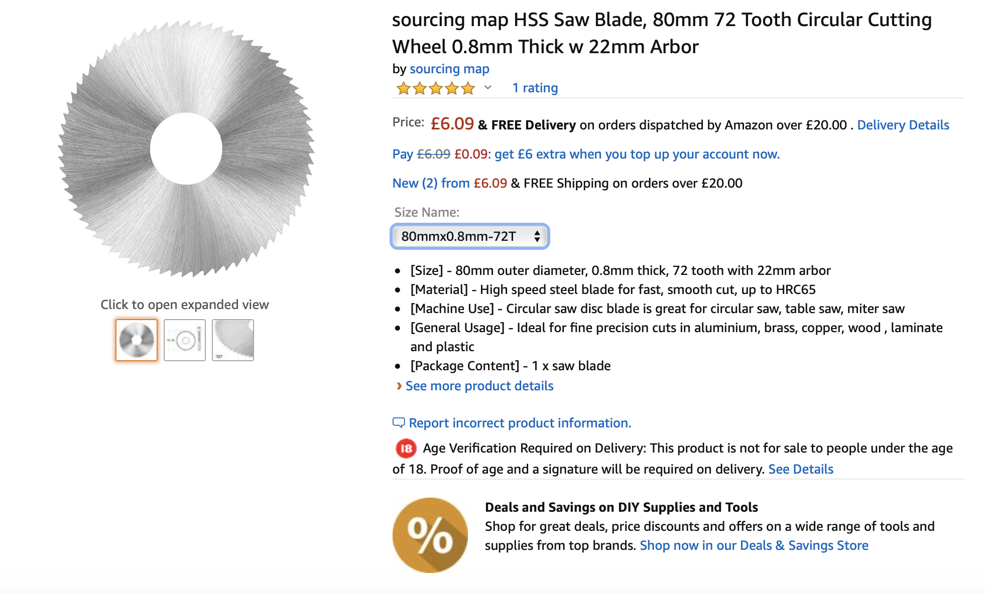
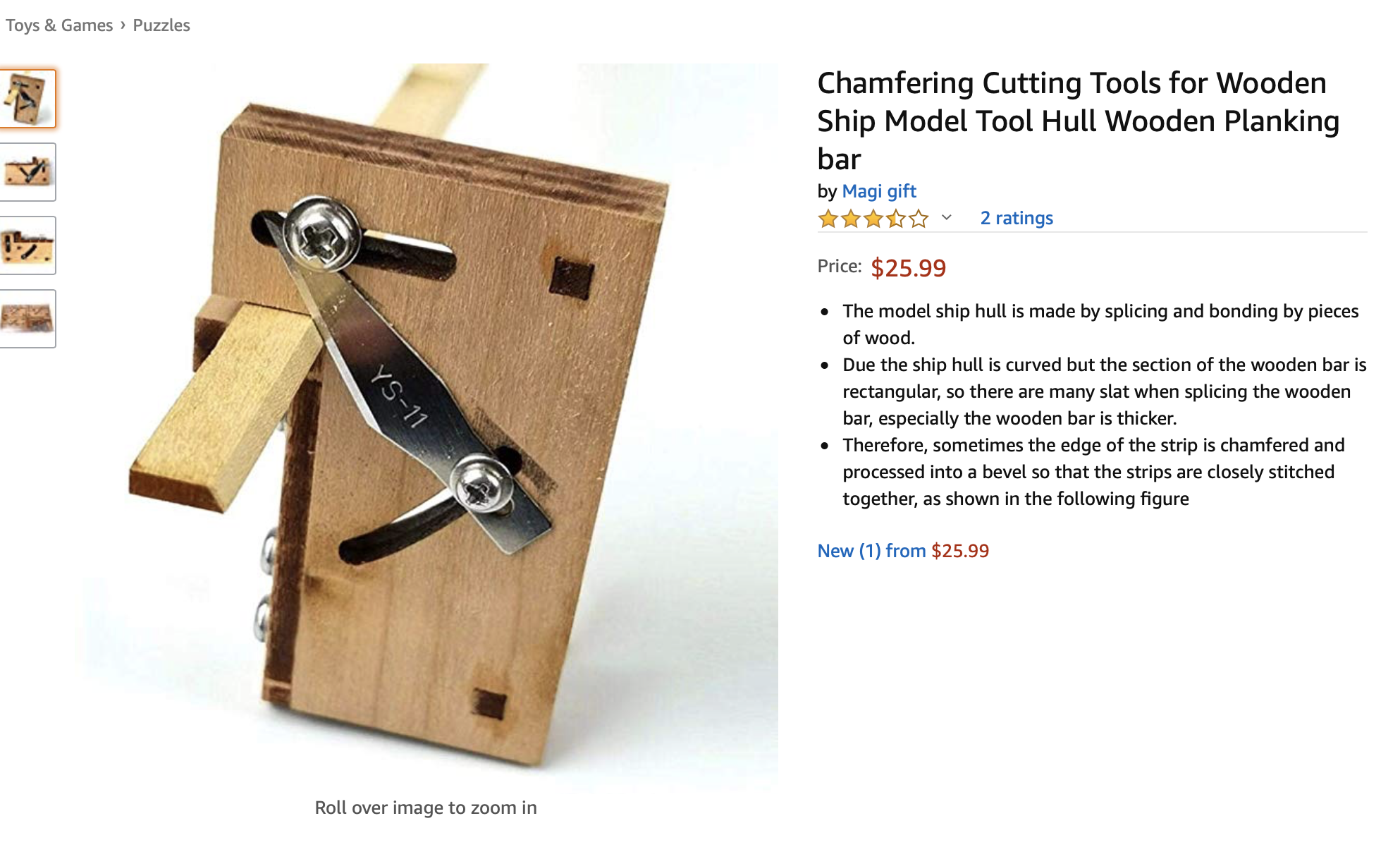
I have Thurston Blades but for several years now I have used these Chinese slitting saw blades. They work fine and are cheap enough to throw away when blunt. I have to say however that I can rip a lot of planks without them becoming dull. They are on the Amazon UK web site and hopefully will also be available in Canada. They need a 12.7mm - 22mm arbour. A reasonable range of thicknesses and teeth numbers are available.

-
Yes - once you have them you wonder why you didn't buy them years ago. Like Eberhard I was intrigued by the way you made the mast bands. Very clever.
-
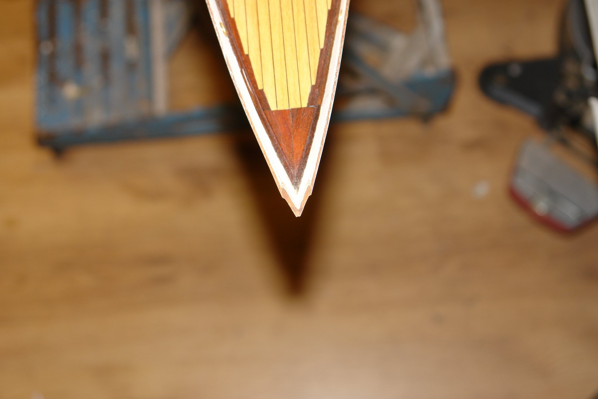
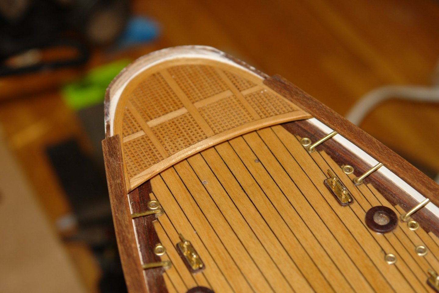
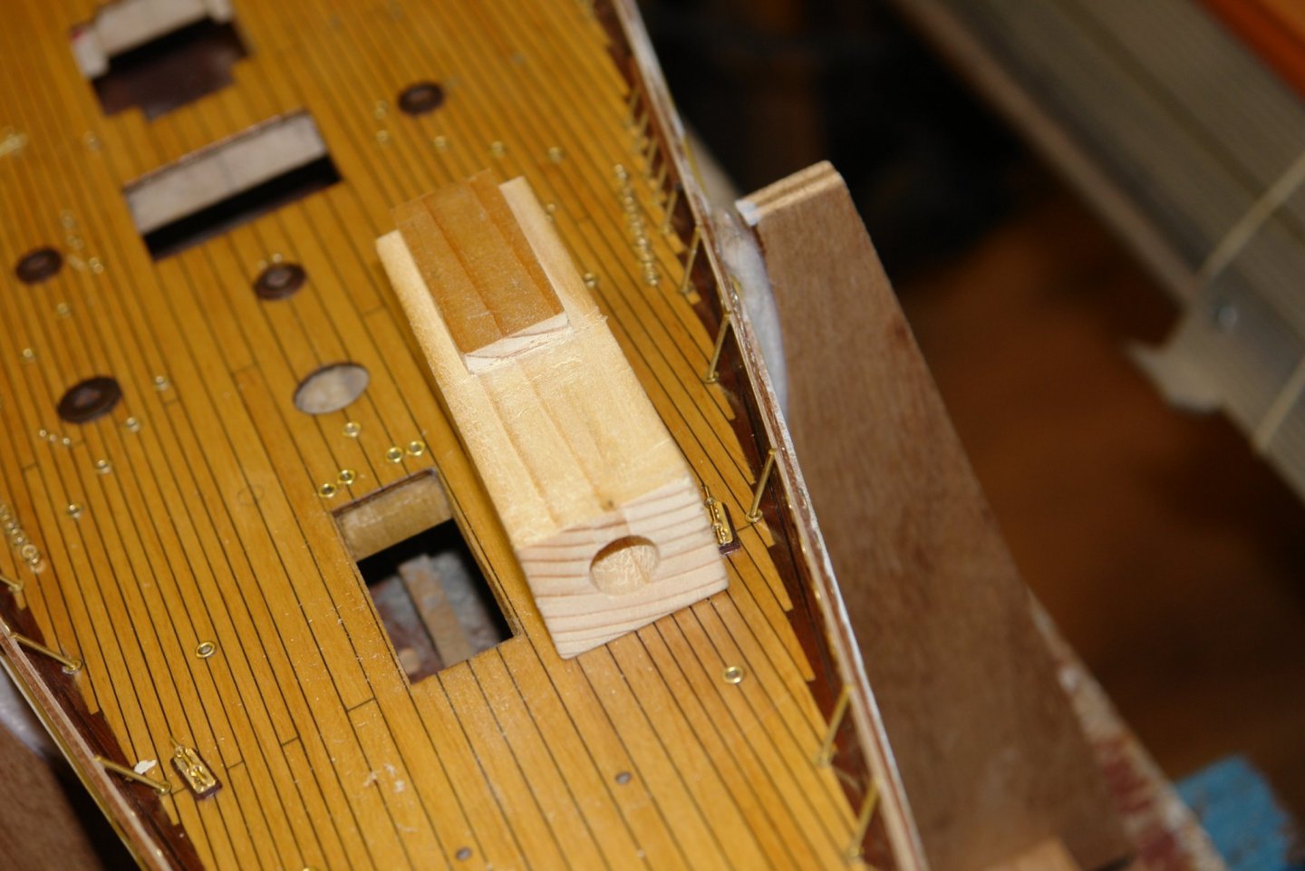
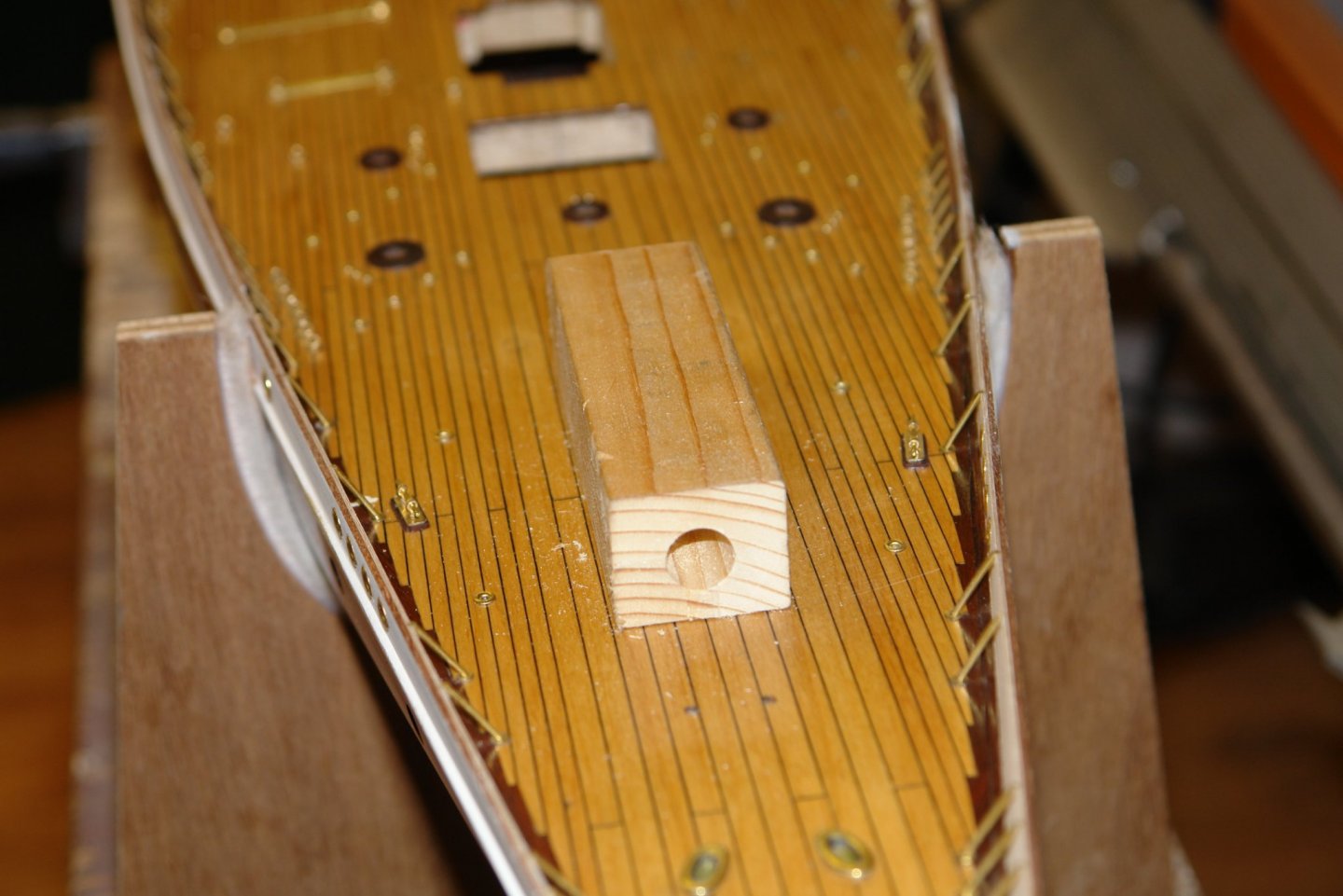
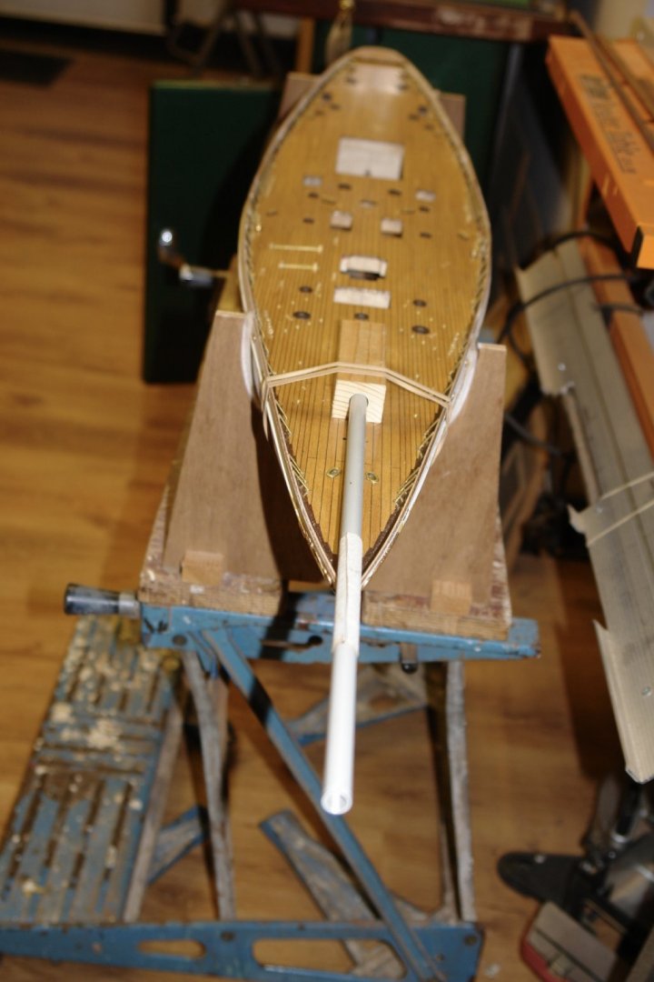
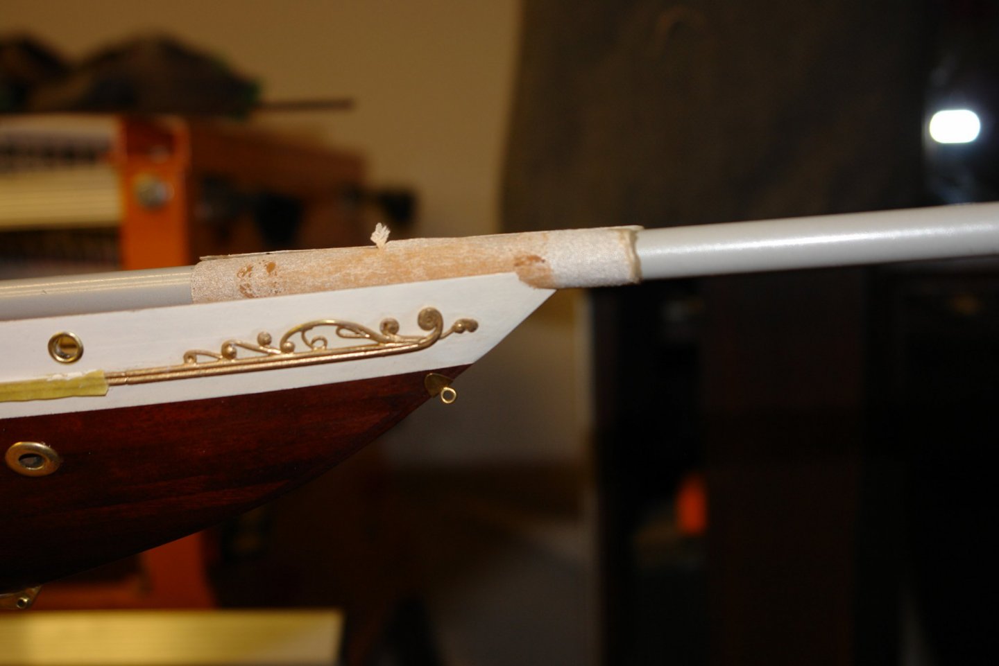
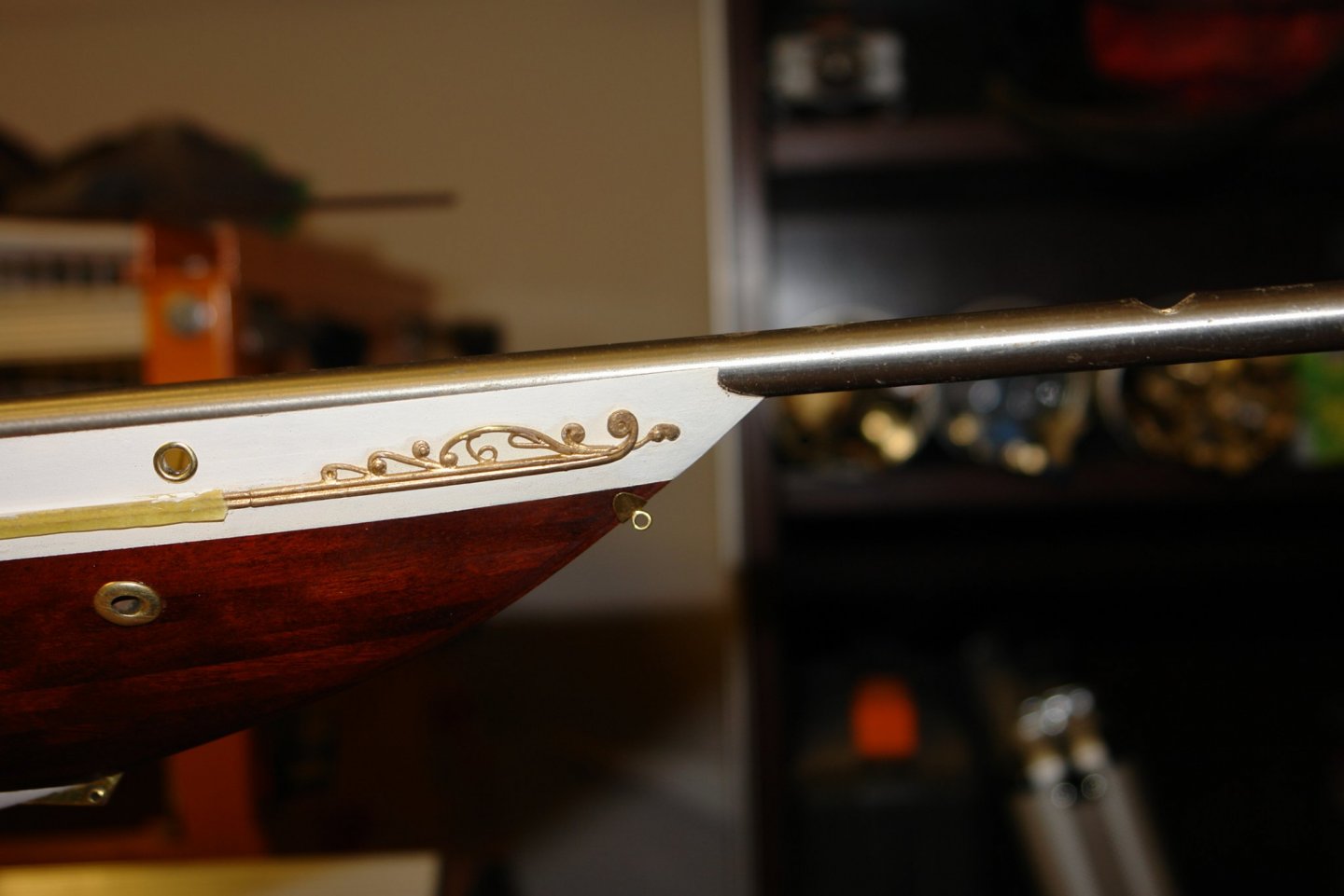
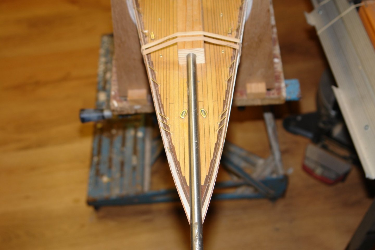
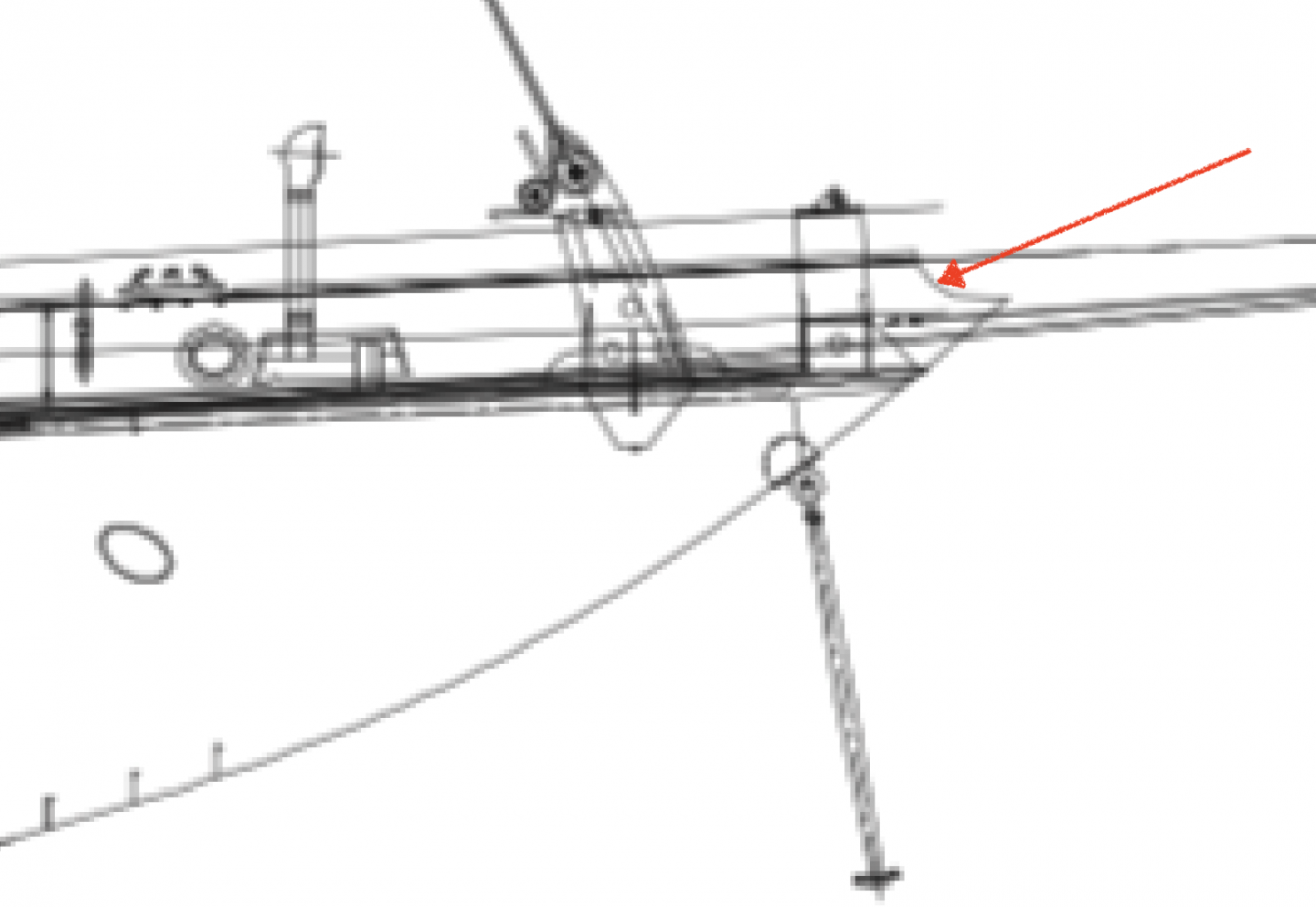
Keith, Roger, Bedford, thank you for the positive feedback. Pat - I look forward to your return to the workshop and your next post. I did make a bit of progress towards installing the bulwark cap rail, namely forming the cutout at the prow for the bowsprit. This is quite a complex cut away formed by the intersection of the bowsprit and the outward sloping bulwarks. It was also a good opportunity to make a (hopefully to be avoided) mess of this part of the hull - . The expected shape is quite well defined on the plans:- I decided the best way to approach forming the cut out was to create a circular sanding rod the diameter of the cut out and use this to sand away the bulwarks until I had reached the required depth - about 1/4". I wanted to make sure the sanding operation was well controlled with the sanding motion being axial along the centre line of the boat. To achieve this I created the block in the following photo:- The block had one face machined away to leave an up-stand that fitted tightly into the hole for the forward deck house. A hole of the diameter of the bowsprit was machined axially along the block at the height of the bowsprit above the deck. A a steel tube of slightly less diameter than the bowsprit was then selected and 120 grit oxide paper was glued to it to bring it up to the bowsprit diameter. With the wooden block held in position by elastic bands, sanding of the cutout commenced. The fore and aft sanding motion being constrained by the guide formed by the wooden block. With this setup I carefully sanded, checking frequently with a steel bar of the same diameter as the bowsprit. After about half an hour of careful work I had produced the required shape. I am now in a position to commence the cap rail.

-
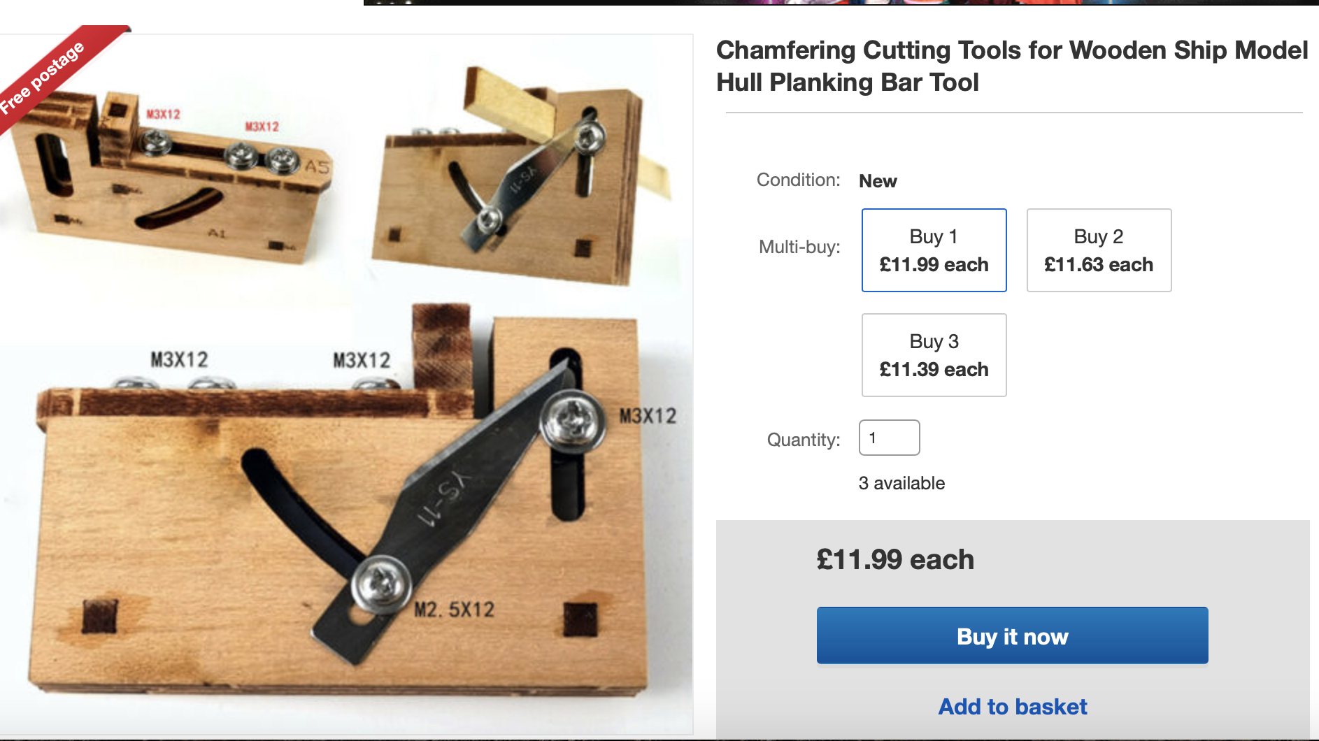
also here Amazon - dollar price seems excessive
-
I found it here - ebay UK

-
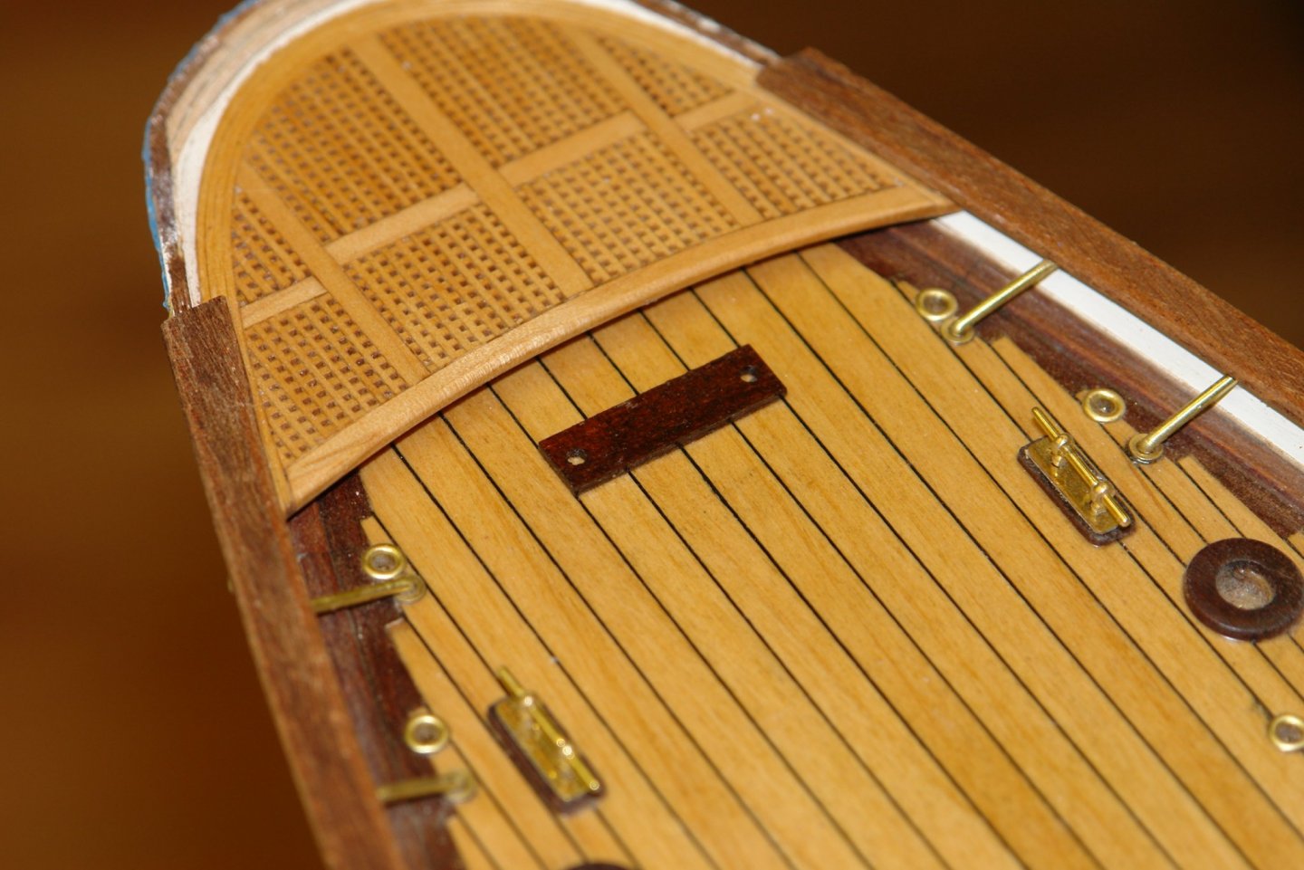
Nice work on gratings Paul. Merry Christmas.
-
A cute little vessel Jon. I look forward to seeing how it turns out. Merry Christmas.