


Cathead
-
Posts
3,348 -
Joined
-
Last visited
Content Type
Profiles
Forums
Gallery
Events
Posts posted by Cathead
-
-
So I've had a fun week trying to figure out a sail plan for this longboat. Once I started studying the rigging shown in the plans, and trying to envision how sails would work, it just didn't make sense. I'm not an expert sailor, but I did sail some growing up, and I just couldn't figure out how the rigging plan shown in the model could work in real life. I created a separate discussion (linked above) in the Sails & Rigging section of MSW to explore this question, and got some really useful advice. Here I'll summarize the problem and the solution I've settled on.
I did find several other longboat builds that included sails, and I'm going to use them to illustrate both my concern, and my solution.
The problem:
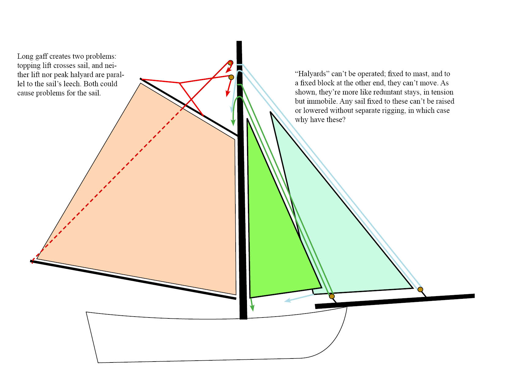
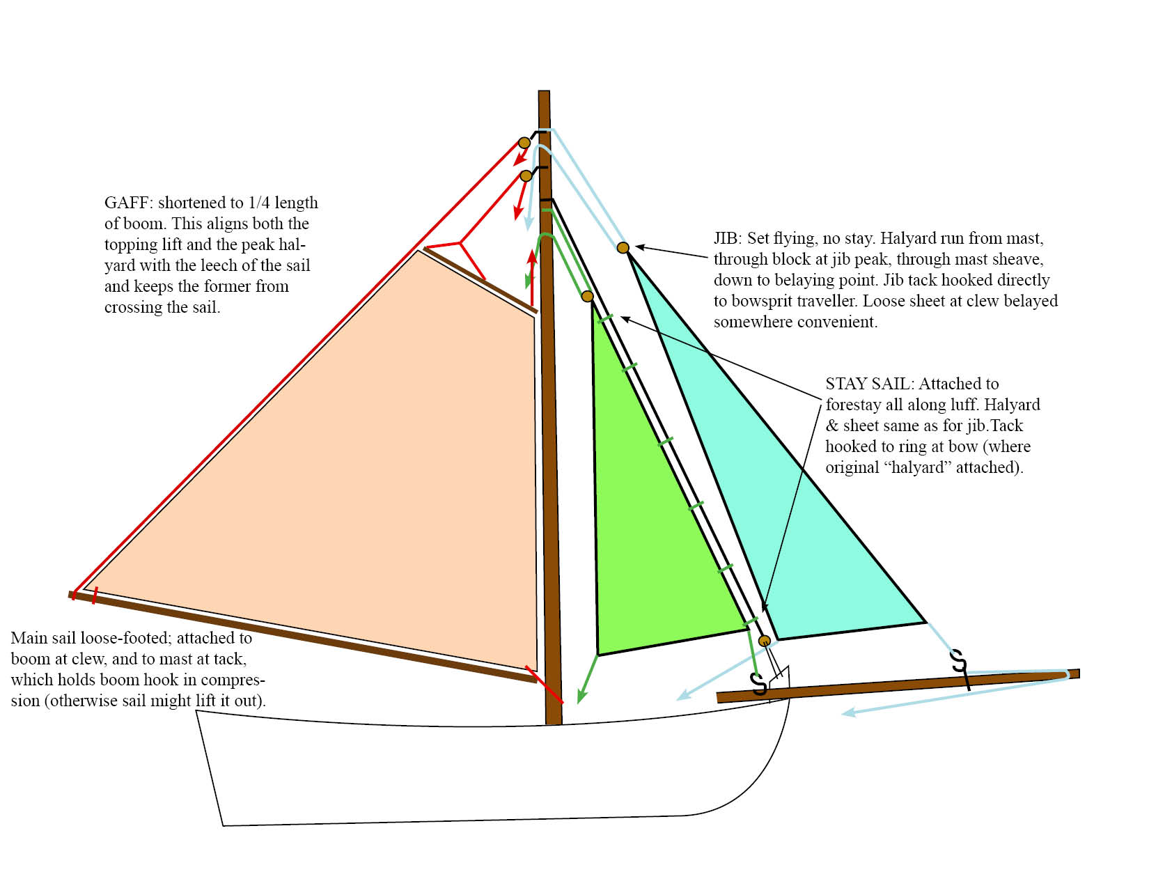
The diagram below lays out the problem with the foresail halyards that I couldn't understand, and a problem with the gaff that was pointed out to me in the other discussion. I hope it's self-explanatory.

For example, on this very nice build by greatgalleon, look closely at sails, which are attached directly to the halyards as shown in the instructions. They look great, but how could they have been raised or lowered? There's nothing mobile about this rigging. Also notice how the topping lift crosses the sail; if the sail fills in that direction, it'll interfere with the sail's ability to catch wind. Important: I'm NOT criticizing this build, just using it to illustrate my concern about the functionality of the rigging as shown in the instructions.
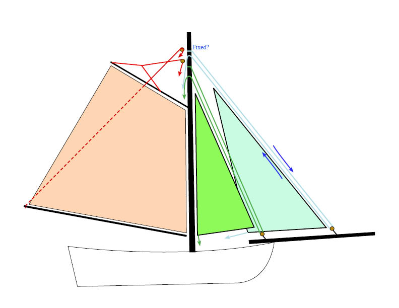
The solution:
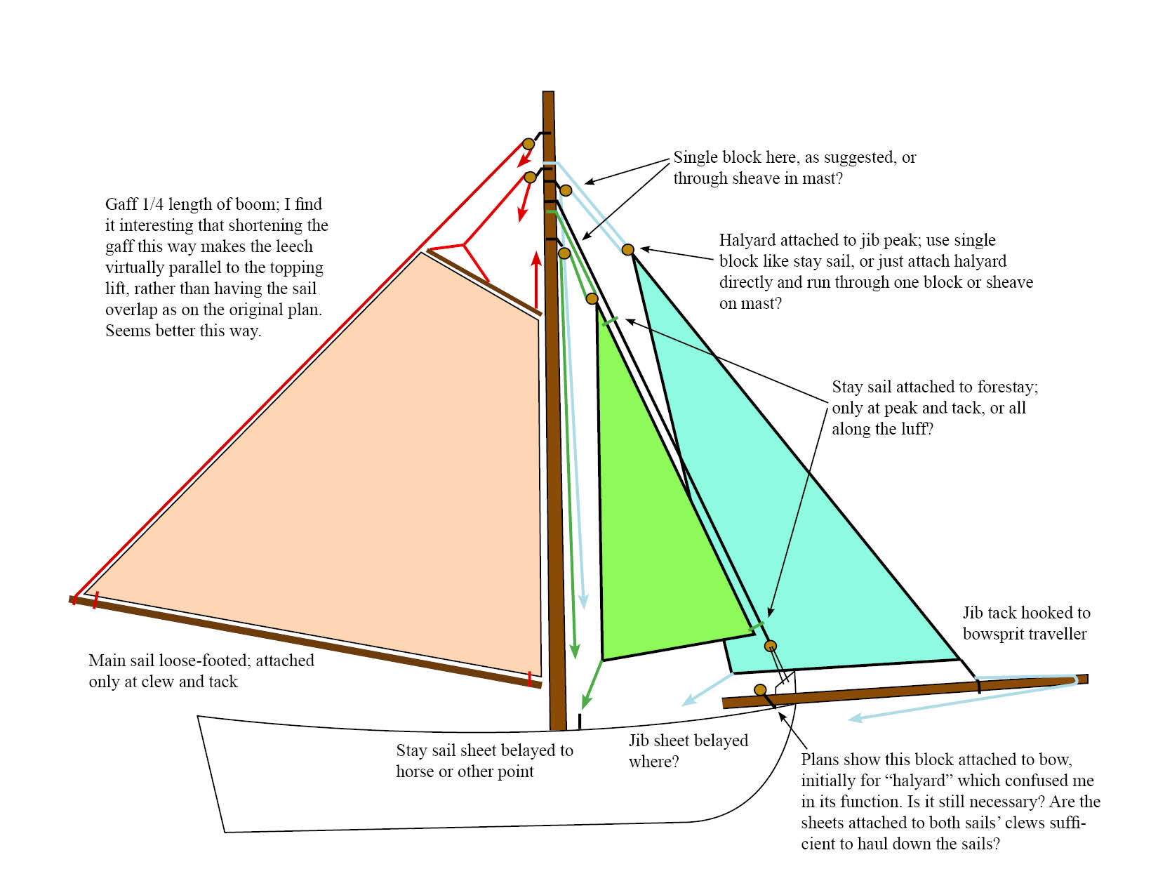
The diagram below lays out my solution, after some discussion in the other forum.
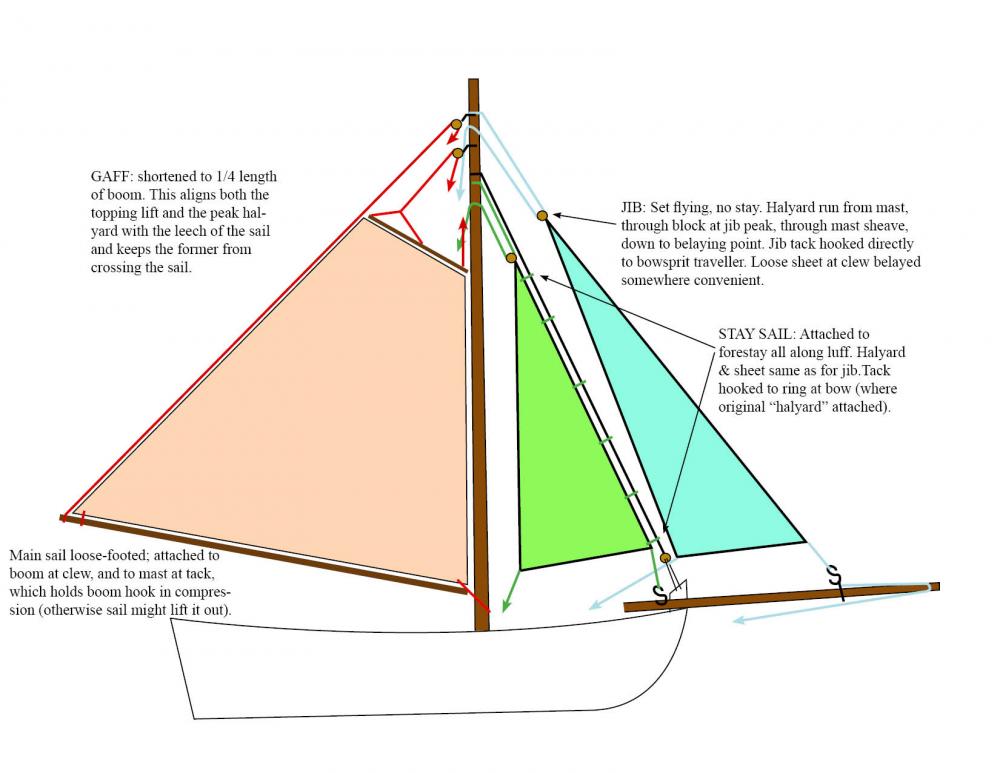
For example, on this very nice build by samueljr, he solved the problem by attaching additional blocks and rigging, using the original "halyards" as extra stays from which to hang the sails. This works, but adds a lot of extra rigging for a boat which had to be routinely rigged and derigged. So I followed a simpler approach, taking out the useless "halyards" shown on the plans and replacing them with a basic rigging that would allow for sail operation with a minimum of spiderweb.
I don't know if my approach is "right", but it's both simple and functional as far as I can tell. I intend to move forward with this plan or something very similar, feeling better now that I have a rigging plan I can actually envision using in a real-life situation.
Progress:
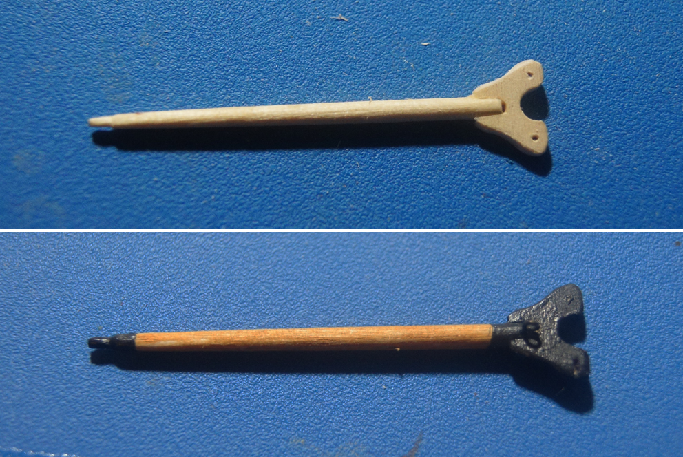
Shortened gaff. I tried to make the two tiny side pieces as shown in the manual, but kept breaking them, so went a different way and formed them as a single piece, fitting the gaff into a narrow slot. Painted and sanded, it looks fine to me and is stronger.
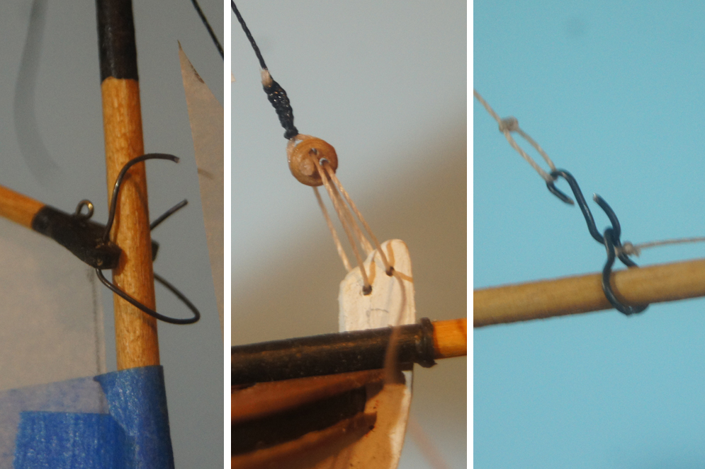
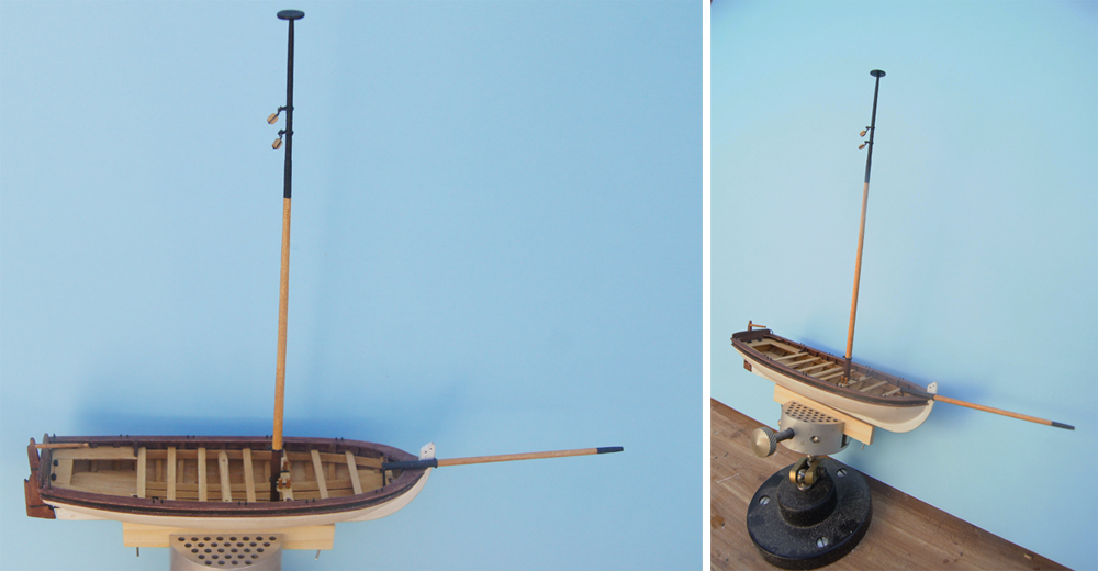
Other attachments. I test-attached the gaff to the mast using a piece of wire, so I could experiment with sail shapes. I attached the forestay temporarily, allowing for further adjustment as I proceed on sails. I formed the bowsprit traveler and made a hook to attach to the flying jib, temporarily represented with a line to the masthead.
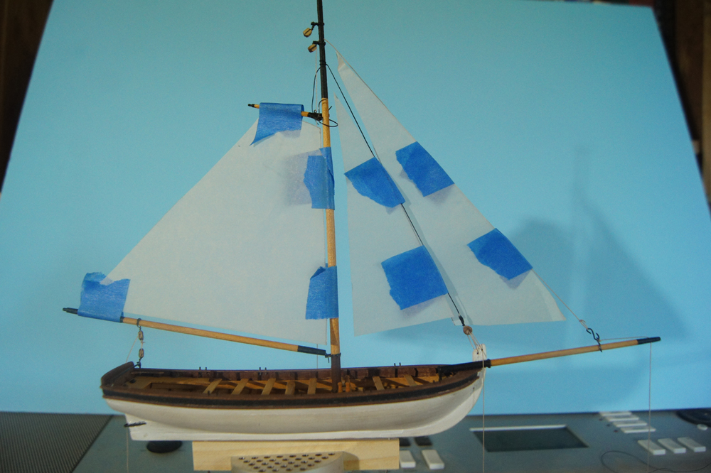
And here's my sail plan tested in 3D. I temporarily rigged a line from the traveler to the masthead to hang a paper sail, though in reality there will be no line there. All the lines are temporarily tensioned by clothespins hanging from their loose ends. Once I decide I like the sail shapes, I'll use the paper cutouts as templates for making the real thing.
-
Many, many thanks, Roger. I feel much better about a rigging plan that I can understand and envision actually using. Next step, I think I'll mock up the sails with cardboard and see how they look in 3D. Hopefully this weekend.
- mtaylor and thibaultron
-
 2
2
-
-
-
Okay, here's an updated sail plan taking your advice into account. I'm including the original one (traced from the kit plan) to make comparisons easier. This arrangement seems more like something I could sail, compared to the original that I just couldn't figure out. I labelled changes on the diagram, and included a few questions for clarification. Most stays are left out for clarity, except for the forestay (which I left off the first diagram but should have included; same for the bowsprit traveller).
Original rigging plan:
New plan:

Other questions:
Do the foresail shapes & sizes look right?
Would there be any lines of reef points on the main sail, or telltales? If so, where?
Many, many thanks to Roger and anyone else who wants to weigh in. I'm really enjoying thinking through this problem.
- Gerhardvienna, thibaultron and mtaylor
-
3
-
Roger, this all fits with what I had been thinking. I will draw up a new plan and see what you think, if you're willing.
- thibaultron and mtaylor
-
2
-
The traveller/tiller arrangement is addressed in the instructions, assuming you're referring to what the instructions call the horse:
"Up to the mid 18th century, the horse was positioned as shown on the model...during the second half of the century, they started making the horse so it actually spanned over the tiller. You may opt to do so as well. But since this model is inspired by several contemporary longboat models in the NMM, it was created as shown on those models."
Along the same lines, much of what you say makes intuitive sense to me based on my own sailing experience growing up many years ago, but it's also the case (as quoted above) that this design is based on period models that were rigged as shown. So clearly there must have been a precedent and reason for having a large gaff sail, and the forward stay arrangements that are confusing me.
Regarding the arrangement of the stay sail you describe, how would such a sail be raised or lowered? The model rigging has a forestay (I didn't include it in the drawing for simplification) to which the sail could in theory be connected, but then what's the purpose of the fore halyard as shown, because with one end bent to the masthead it can't be used to raise or lower the sail unless I'm missing something.
And in the same way, even if the jib is set flying, how could it be raised or lowered without some kind of free-moving halyard? The jib halyard as shown in the kit doesn't really function as a stay, given the traveler on the bowsprit, but also not as a halyard, given that it's bent to the masthead and thus can't move.
I think I'll try to create another drawing implementing what you're suggesting, to see if it makes sense. I appreciate your willingness to talk through this with me. It's a fun mental puzzle to figure out.
- coxswain, thibaultron and mtaylor
-
3
-
Roger,
That's really interesting, thank you. Does using a shorter sail mean using a correspondingly short boom and gaff?
Also, do you have any insight on the second question, about the stay sail and jib?
- thibaultron and mtaylor
-
2
-
So I've been laying out possible sail plans for this model, and have found something I can't figure out regarding the stay sail and jib. I created a new topic under Sails & Rigging to ask this question, hoping it would reach a wider audience. Please tell me what you think, I'm stumped and hope I'm just being dumb.
http://modelshipworld.com/index.php/topic/13442-sail-design-for-18th-century-longboat/
- mtaylor, mattsayers148 and Canute
-
3
-
So I've been experimenting with sail layout for this longboat, and a significant question arises right away. Here is a simplified rigging layout, traced directly from the plans, assuming a gaff sail (red), stay sail (green), and jib (blue) arranged within the dimensions of the rigging as shown in the plans.

First question is, do these sail shapes and layout seem about right? I assume I need a line from the clew of both stay sail and jib, belayed to something (drawn in color)?
Bigger question, am I missing something on the stay sail and jib rigging?
The plans refer to the lines drawn in green and blue as the sail halyards, and I assume these are what the stay sail and jib are bent to. The plans say to seize one end of these to the mast, run them down through a block, back up to a sheave, then down to belaying pins. Yet this arrangement doesn't allow these lines to move, only to be tensioned like a stay; if you pull on the belayed end, nothing will happen because the other end is seized to the masthead. So how can the sails be bent to them if the lines can't move? Doesn't there have to be either another block, or another entire set of lines to raise and lower the sails? Are these lines actually stays, rather than halyards?
The gaff sail arrangement makes sense, but the fore sails don't. Am I missing something?
- Mike Y, mtaylor and thibaultron
-
3
-
I'm working on the Model Shipways 18th Century Longboat, and would like to model it with sails raised (no sails are included or discussed in the kit). I can find lots of references to sail patterns and structures for ship sails, but less for smaller boats of this period.
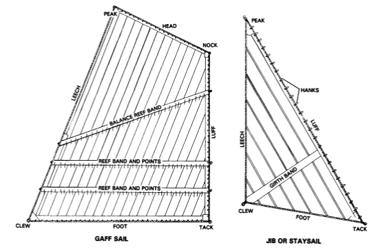
Milton Roth's "Ship modelling from stem to stern" has a very nice diagram of a gaff sail and jib, but I assume from context that it's for a ship, not a small boat. For example, would a longboat gaff sail really need three different bands of reef points? And would the sails be attached to the boom/gaff/stays the same as on a ship?
What would I need to do, or where should I look, to create a reasonably authentic sail design for this model? Is anyone aware of images that would help me get these sails right, including their proper attachment? I've tried searching various terms in this forum without success, so if this has already been addressed, I apologize for missing it and would appreciate direction to the existing guidance. Here's the model as she stands now, for context:

The sort of sailplan I'm going for can be seen in the second image here:
http://skipjacksnauticalliving.blogspot.com/2014/09/fort-mchenry-200-year-star-spangled.html
Thanks!
-
The past few weeks, I've been slowly working on the mast and bowsprit. These have been challenging, particularly the metalwork. Most build logs I've read seem to just skip past the metal work ("The mast is done") or use an alternate method that I don't have the equipment for (creative soldering).
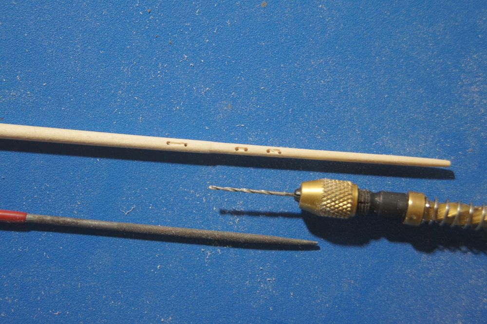
Things started out well. I marked the location of the sheaves on the mast dowel, and pre-drilled the holes before shaping it, figuring this would be easier. It was. Once the holes were in, I hand-sanded the mast down to shape. The plans show a pretty clear "step" in the mast between the lowest sheave and the upper two, but the instructions don't say anything about why this is there. I followed the plans. Why is this there? Anyway, once the mast was shaped I used a small needle file to gouge/file the sheave slot. Result seen below, pre-staining. I think it came out ok.
I found that I simply couldn't drill the tiny holes in brass strip necessary to form the mast rings. I tried, over and over. Doing it by hand, with a simple twist drill, just didn't work. My holes ended up off-center or otherwise screwy, and even when I did get one through, the strip was so thin that the drilled area became a massive weak point. I definitely tried the suggestion I'd seen elsewhere, to drill one side, form the hoop, then use that first hole as a pilot to drill through to the other side. Sensible, but just didn't work for me, just not skilled enough I guess. I went through so much brass I got nervous I wouldn't have enough to finish the kit.
As it turned out, a comment in ggrieco's build log gave me a way forward; Kurt Van Dahm noted that he was very comfortable with the longevity of BSI brand CA, which is what I have, so I decided to try using the gap-filling CA the way others had used solder. The instructions suggest you can use glue to attach the brass rings together, but I went a step further and used the CA to actually create a solid "gap" between the two halves, just enough to drill through:
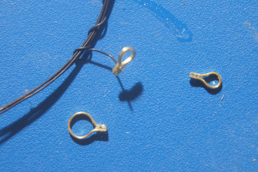
Doing this meant that all three rings had holes drilled through top-bottom rather than sideways for the upper two, but I think this will be barely noticeable in the final model, and it meant I didn't have to twist the brass 90 degrees, something I had also failed to accomplish satisfactorily. Above, you see the three rings formed and drilled, with one strung on a piece of wire as proof of concept. I actually strung all three on wire for painting, both for ease of handling and to keep paint out of the hole. I don't know if this is a good approach or not, but it's what I did, so we'll find out over time. I'm happy with the resulting appearance, at least. I found tlevine's and dcicero's logs particularly helpful in finding a way around my metalworking impass; thanks to both.
I also solved another problem: how to hold the model going forward.I didn't want to place it in a clamp for risk of damaging the hull, but also didn't want to mount it on a permanent base yet. I had pre-drilled mounting holes in the keel, and had the bright idea of running wire through a "blank" of wood that would fit into my flexible work clamp:
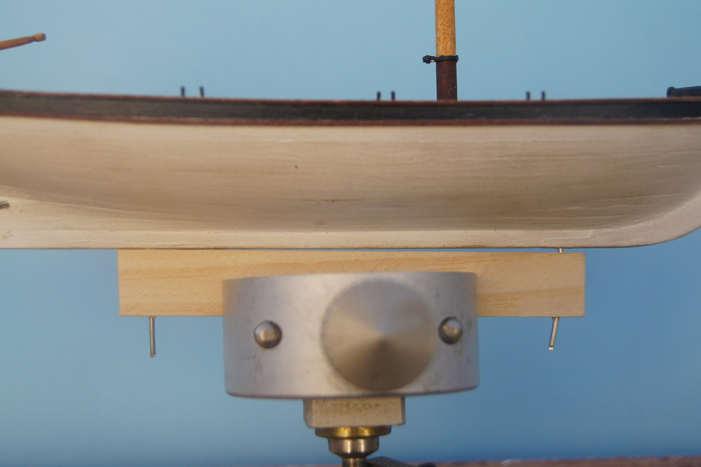
I'm really happy with this setup. Now I can angle model in any direction I need for working on delicate rigging, the hull is out of any danger, and the wire can bend a bit to absorb some shock from any accidental bump. When I'm finished, I'll just replace the "blank" with nicer pedestals of some kind.
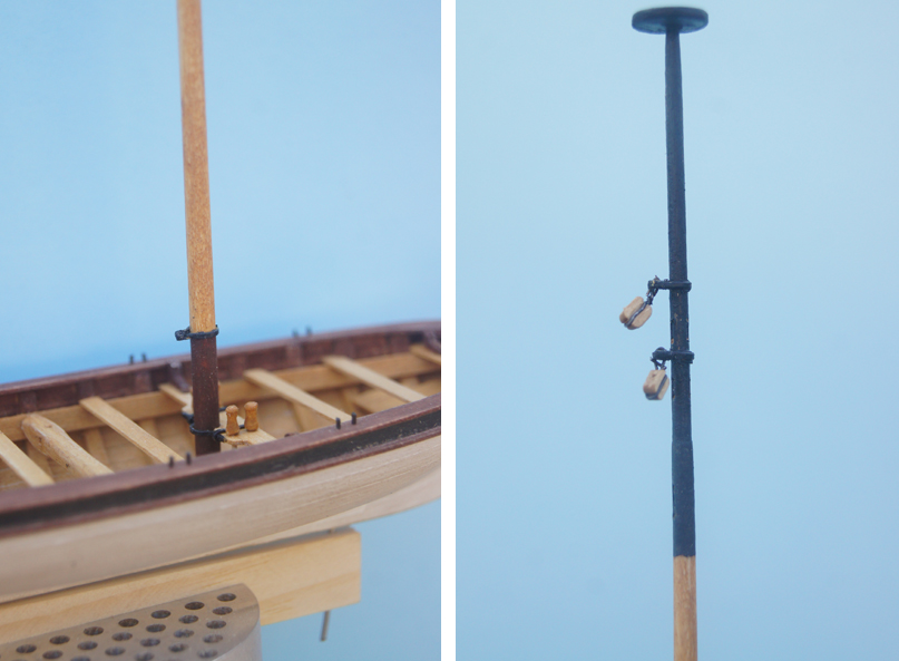
With this in place, I worked on finishing and painting the mast and bowsprit. The latter was straightforward, with the sheave formed just as on the mast, and the metal work done with the same method. I used the paint scheme shown on the plans, just replacing the red with cherry stain as I've done elsewhere. Here's a closeup of the mast and metalwork, with blocks attached:
And here's what she looks like now, with mast and bowsprit attached. I've been keeping the rudder locked away so I don't damage it accidentally, but placed it on for these photos.
Next up, I have some research and planning to do. I want to model this with sails attached and raised, which is not part of the plans, so I need to figure out just what those sails would look like, and how to set things up properly. Right now my working idea is to make the boom, gaff, and sail as one assembly off-model, then rig it all together, then attach a jib. Thoughts?
-
-
She sunk in 1943? Must've been one desperate U-Boat Kapitan.
- mattsayers148, CaptainSteve, Elijah and 2 others
-
5
-
Kurt, that's a really useful and interesting perspective. I've read the warnings about CA going brittle, too, but didn't have enough experience to judge. I looked at my bottle, and sure enough although it's Model Expo brand, it's the BSI maker that you recommend. Now I feel better about using it!
Glenn, thanks for your answer. It makes a lot of sense, and certainly gave me more to think about for future builds.
-
Hearty congratulations! It's been a fascinating project to follow, full of creativity and education. Many thanks for the time you spent sharing it with us.
-
-
-
Keith, that's a really interesting model. Is there a specific prototype, or something whimsical you came up with?
- Keith Simmons, Gerhardvienna, Canute and 1 other
-
4
-
Looks really nice, Glenn. I wish I'd taken better photos of the boiler construction on Bertrand. It wasn't my favorite part of the build, either, both in the doing and in the result. Kinda nice to know I'm not the only one! What you've got certainly captures the feel of a typical steamboat boiler, which since it's speculative anyway, is more than good enough. And as on most boats, the boilers kinda get buried under the shadow of the boiler deck anyway, so any little mishaps fade from view.
Speaking of which, what's that slatted structure over the boilers in your drawing? Some kind of screen nailed to the outer stanchions? What's it for? Whatever it is, it'll also help hide any boiler imperfections.
Edit: also meant to ask, how did you emboss the rivets? By hand or with a ponce wheel? Curious to know what you tried and what you'd try differently in the future, since you didn't like the result.
-
Got a general question. How much wood does a paddle wheeler like the Herion use.
I wasn't sure if you meant how much firewood was used to run a steamboat, or how much wood was used in construction, so here's my take on both. Good question either way.
Firewood (from Steamboats on the Western Rivers, Louis C Hunter): "Steamboats of the smaller classes burned 12 to 24 cords of wood every 24 hours, and the larger boats running at mid-century consumed anywhere from 50 to 75 cords per day."
Also, keep in mind that firewood quality varied tremendously along western American rivers, everything from well-cured oak with lots of heat potential to green cottonwood that was barely worth burning. Early boats (like Heroine) probably had to cut their own wood daily as they worked up-river (salvaging driftwood, dead trees, live when necessary), whereas woodlots began to proliferate along navigable rivers as traffic developed, meaning that boats could stop and buy wood daily instead, often finding better-quality stuff as woodcutters could stack and cure wood for later sale knowing that boats would be coming along. Especially on the Missouri River, this too changed along the route, as the river slowly left behind forested areas and extended into the mostly treeless plains and prairies of the Upper West.
Construction (from The Western River Steamboat, Adam Kane): "According to the 1880 census, the shipyard at Sewickley PA consumed 100,000 to 225,000 feet of oak, pine, and poplar in the construction of each steamboat hull between 180 and 260 feet long...this equates to approximately 20-50 old-growth trees per hull".
Early boats were built tough and heavy, simulating maritime construction, but builders quickly realized this wasn't the way to go about things, and starting building them lighter and lighter, using less oak and more pine & poplar, and using thinner pieces. American riverboats needed to be light and flexible, not hefty and rigid like an ocean-going ship.
- CaptainSteve, Canute, mtaylor and 1 other
-
4
-
John, Kurt, or other moderators: given the immediate interest expressed in riverboats worldwide, should we just change the title of this topic to something like "Steamboats and rivercraft - general discussion"? I'd be happy to edit my opening post to make it less focused on the US if we all think it's better to have this topic broadened.
Keith & leclaire, welcome to the steamboat addiction! To the latter, at risk of self-promotion, check out my build log for Bertrand. If I can scratch-build a steamboat, then I suspect many others can as well.
- Altduck, Keith Simmons, mtaylor and 2 others
-
5
-
Hey, John, I sure don't mind if folks want to talk about riverboat anything. I set this up the way I did, in part because US boats are all I know, and because it seemed to be the focus of models here right now. But it's neat to learn anything that anyone wants to share, and I hope I didn't offend anyone by making it US-centric. Your photo of the Adelaide shows a really neat craft that's noticeably different from anything in the US. Thanks for sharing!
- Gerhardvienna, Rick01, ggrieco and 4 others
-
7
-
Wow, Gerhard, that's a new one for me. Recently, reading a book on the Ottoman Empire, I found a maddeningly vague reference to the British army using steamboats to transport troops and supplies up and down the Tigris & Euphrates rivers during WWI. Would have loved to know more. I really only know anything about American vessels, and only so much about that. So much history, so little time.

Sail design for 18th-century longboat?
in Masting, rigging and sails
Posted
So here's my "final" vision of the rigging, and a photo of testing the sails on the model. I posted the same images, and some more summary discussion, over on my build log, but wanted to share these here, too. Thanks again for all the advice!