


Moxis
-
Posts
314 -
Joined
-
Last visited
Content Type
Profiles
Forums
Gallery
Events
Posts posted by Moxis
-
-
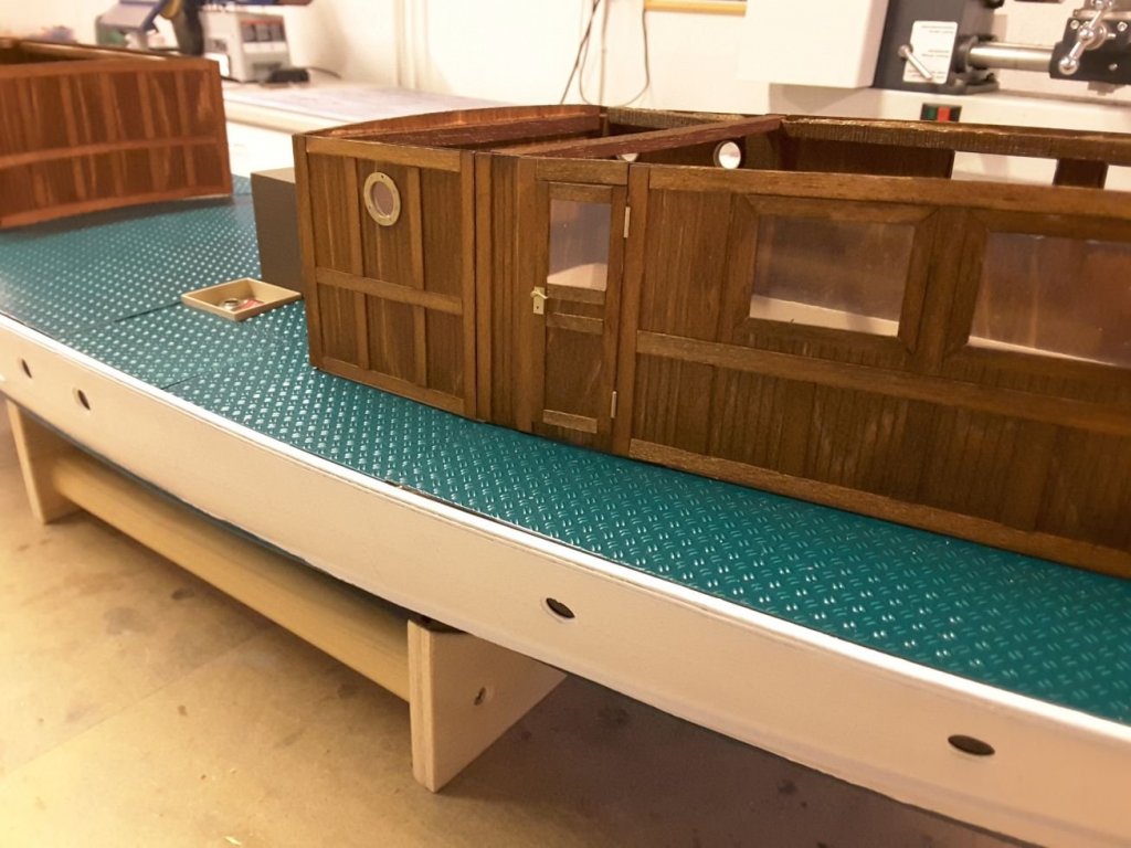
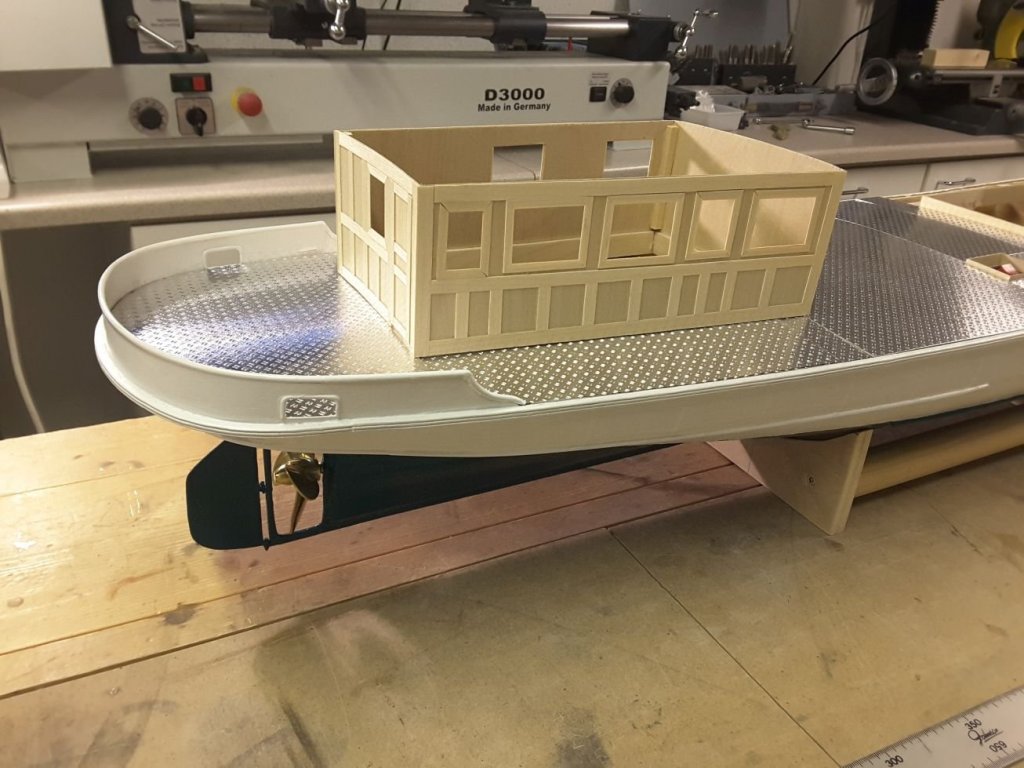
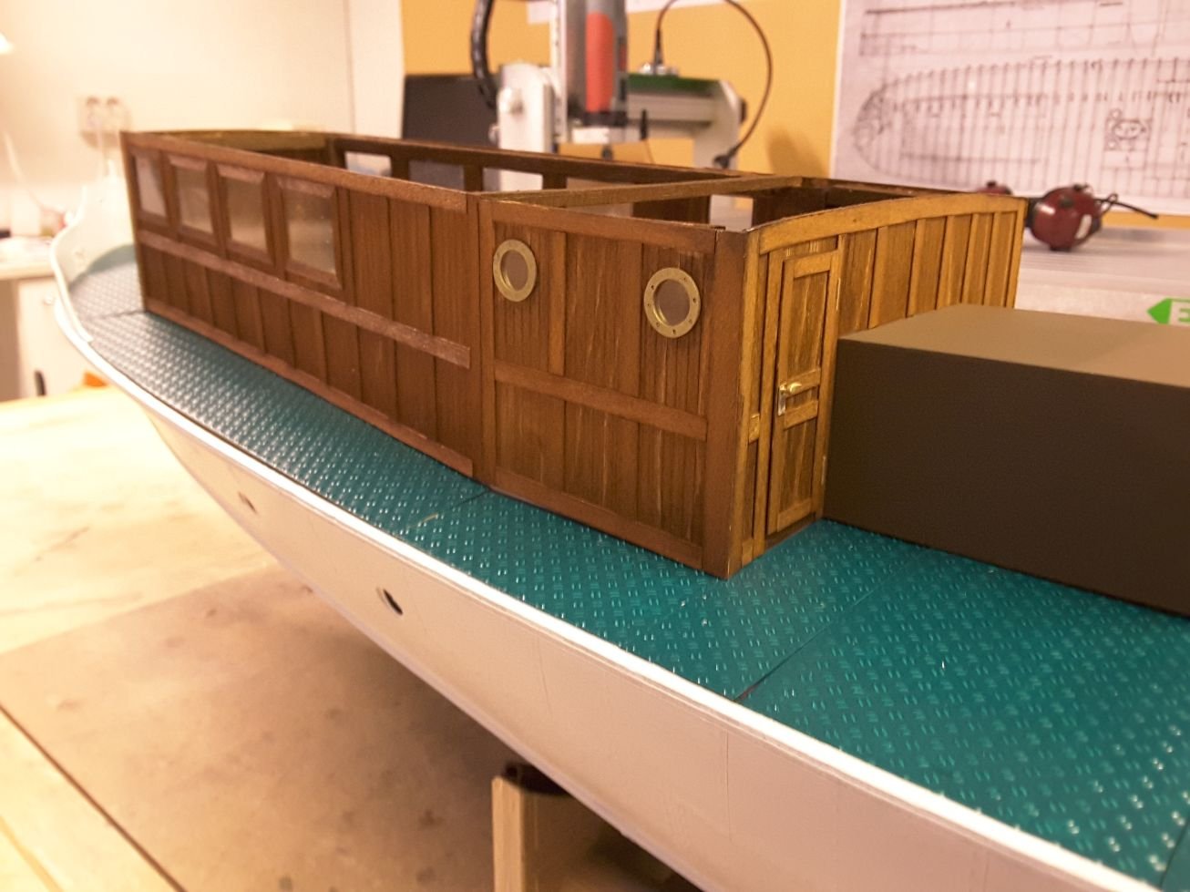
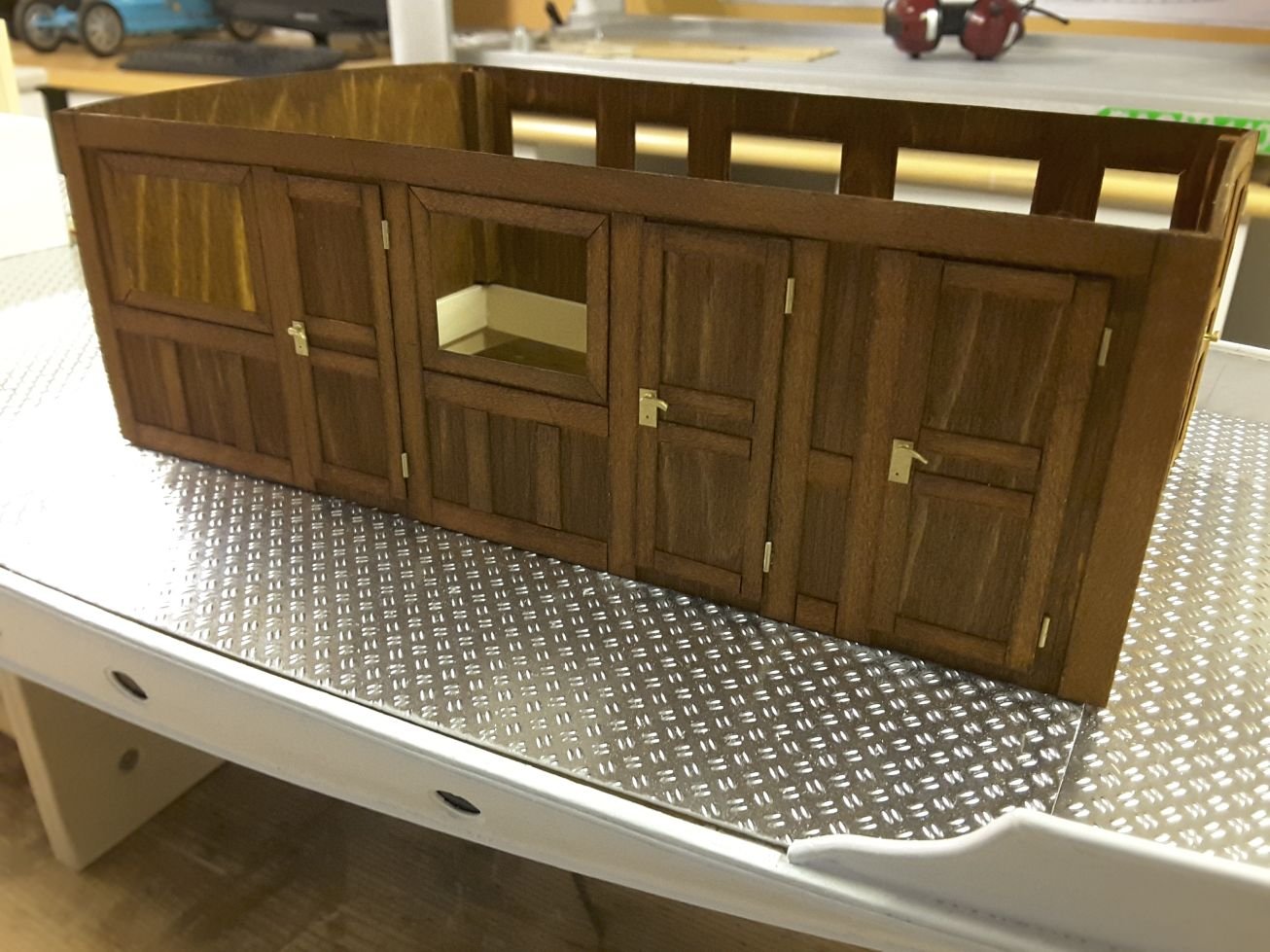
Deck plates have been painted but not yet glued into the hull. First with etch primer and when dry, with the same water diluble half matte green as the bottom. Main deck cabin structures are also ready. They were built of 1 mm birch plywood and 0,6 mm birch veneer. Hinges, locks and hand pieces are styrene, painted with brass coloured model paint. And windows are transparent plastic sheet.
I have thought not to build any interiors like chairs, benches and tables in order not to add too much weight to the upper structures, but that is not yet sure. What do you think? Should them be built? and if yes, of which material?
Next I have to concentrate into a very challenging work: To build the middle and upper deck. It must be light, thin, and bending in two directions. Plain plywood is not good, it doesn`t bend in two directions, and does not keep it`s form nicely. Any suggestions?


-
Thanks for comment Kees. Yes, the plating work was interesting to make for me too. Only time will tell if it lasts without breakages or not. Anyway easier than make the whole hull out of metal by riveting. But I have seen that too, in some model exhibition in Germany years ago. The guy was riveting brass plates into his hull during the exhibition, and the result was fabulous.
-
-
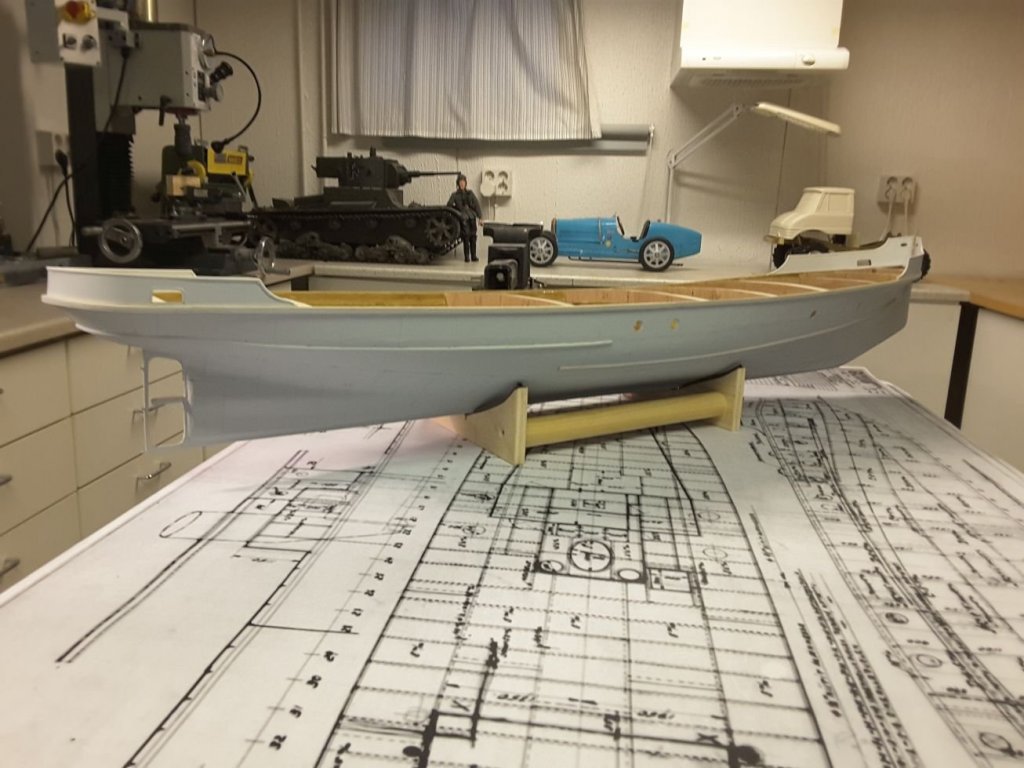
Finally the Christmas season is over and I could continue shipbuilding. The next item was deck building. From previous projects nice scale 0,5 mm aluminum chequerplate was left over, so I decided to use that for the deck. But unfortunately the left overs were soon consumed, and more plate had to be bought from a company in Germany.
The deck consists of many plates, of which I made carefully garboard templates first, and only after satisfied with them, cut the final plates with jeweler`s saw and very fine blade.
Deck plates will be sprayed first with etch primer, and after that painted with green paint. Nobody knows the original color of the deck, but during the sixties it has been painted green, so I will use that.
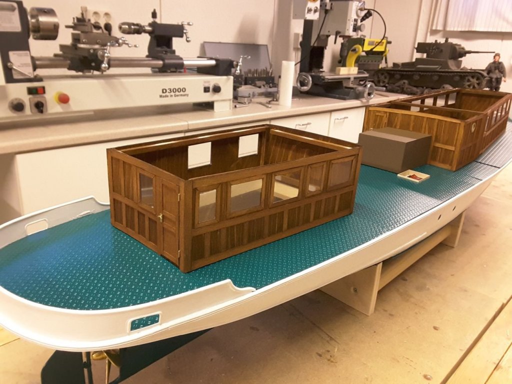
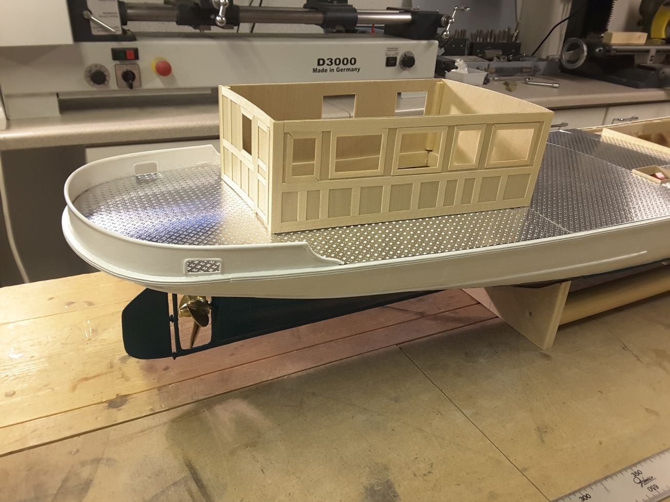
After the deck plates were made, I started to make the main deck upper structures. They have to be very light to keep the center of gravity as low as possible, so I decided to make them of 1 mm aircraft quality birch plywood and 0,6 mm veneer. First I thought to build internal structures too like chairs, benches, tables, etc, but they would add too much weight to the upper parts of the ship, so I decided to omit them and build only the walls.
Deck building was started from stern. This plate will be removable, in order to get into upper end of rudder axle, if necessary. Other plates will be glued permanently into the hull.
Half of the deck made. At this point I was run out of the chequerplate and more had to be bought. The supply from Germany was not so fast as anticipated, so there must have been long Christmas holidays also in Germany.
Finally new plates arrived and work could continue.

Upper structure walls for main deck were built using 1 mm birch plywood and 0,6 mm birch veneer.
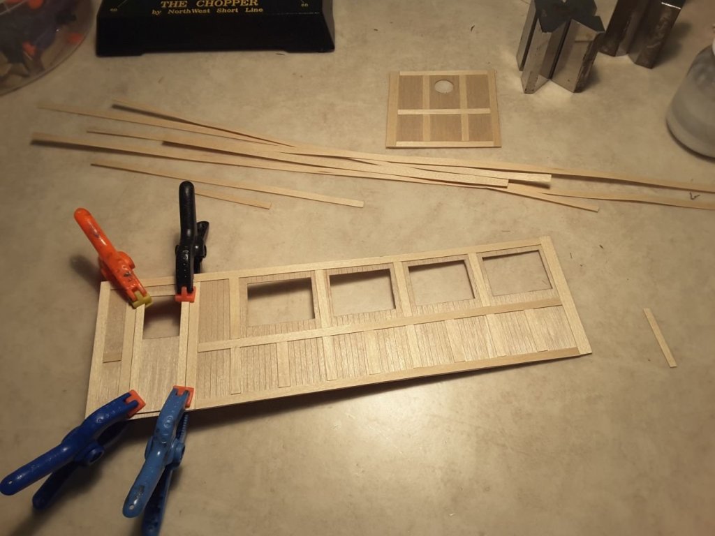
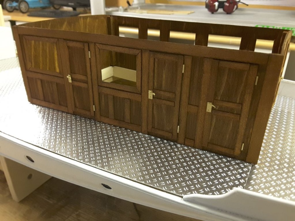
The sternmost structures on the main deck ready waiting for details and staining. Mahogany colored stain was used.
Door handles and hinges were made of styrene, painted with brass colour and glued into doors.
-
-
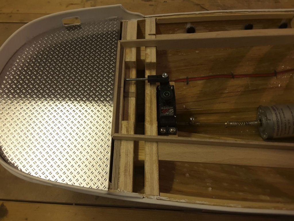
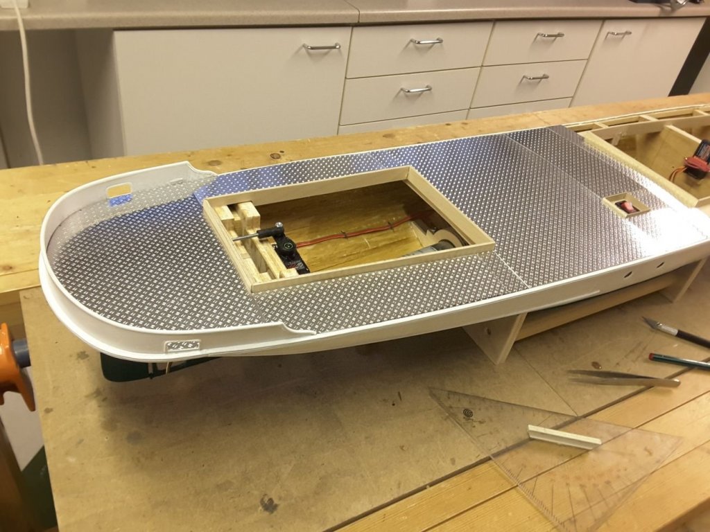
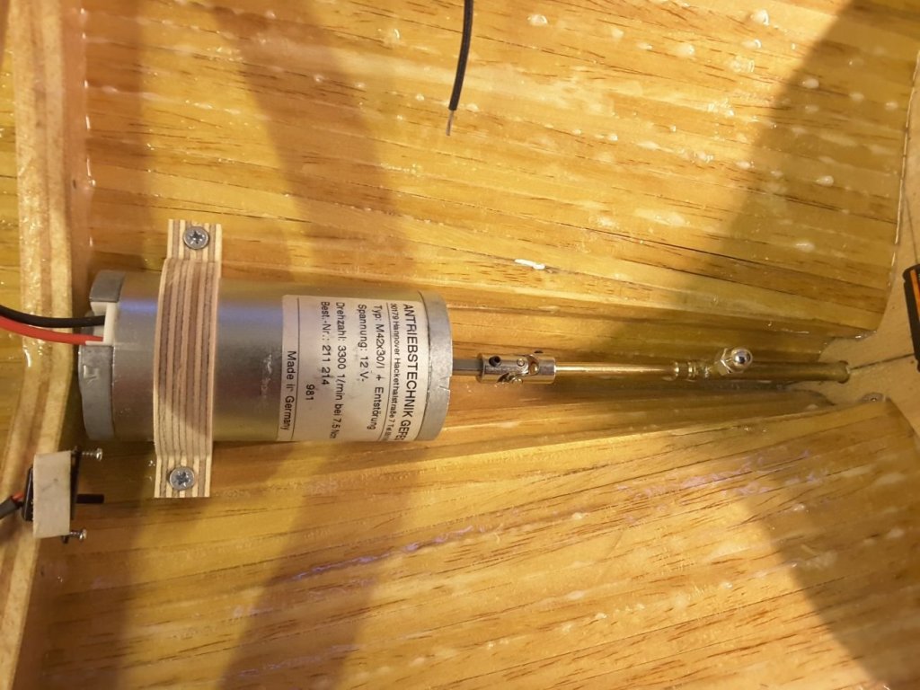
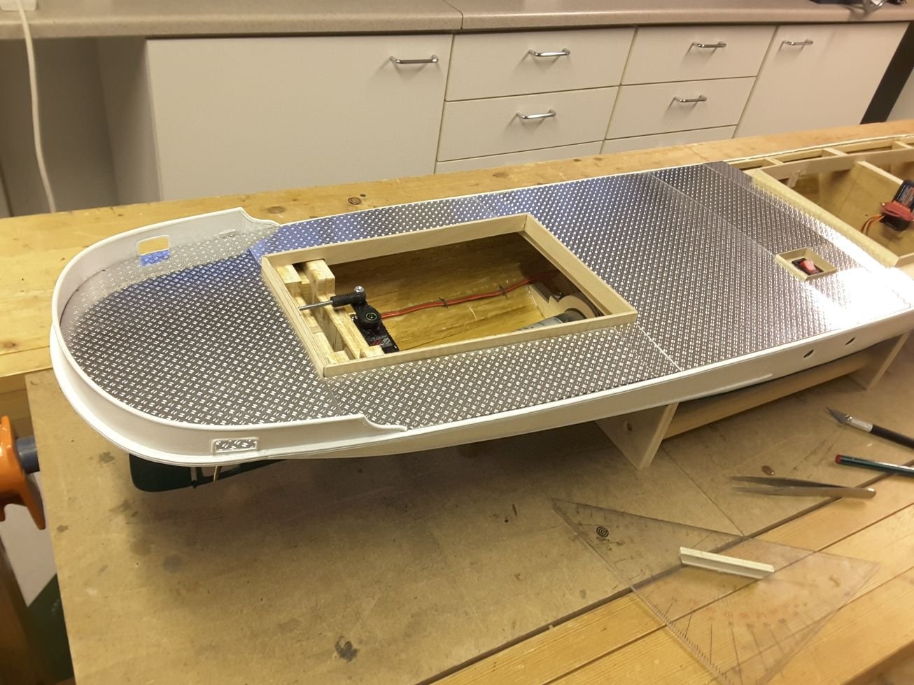
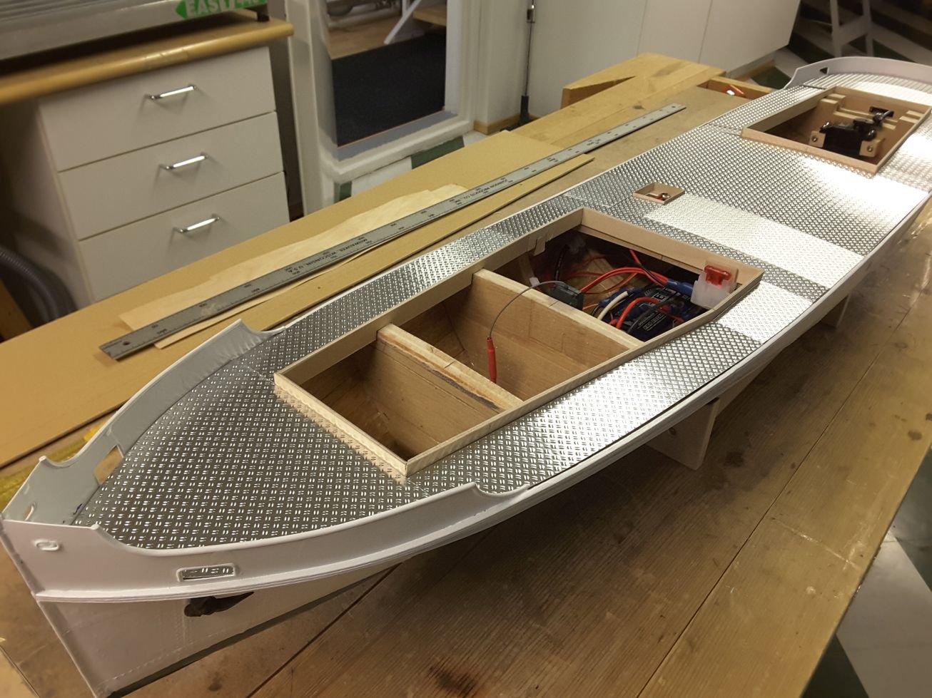
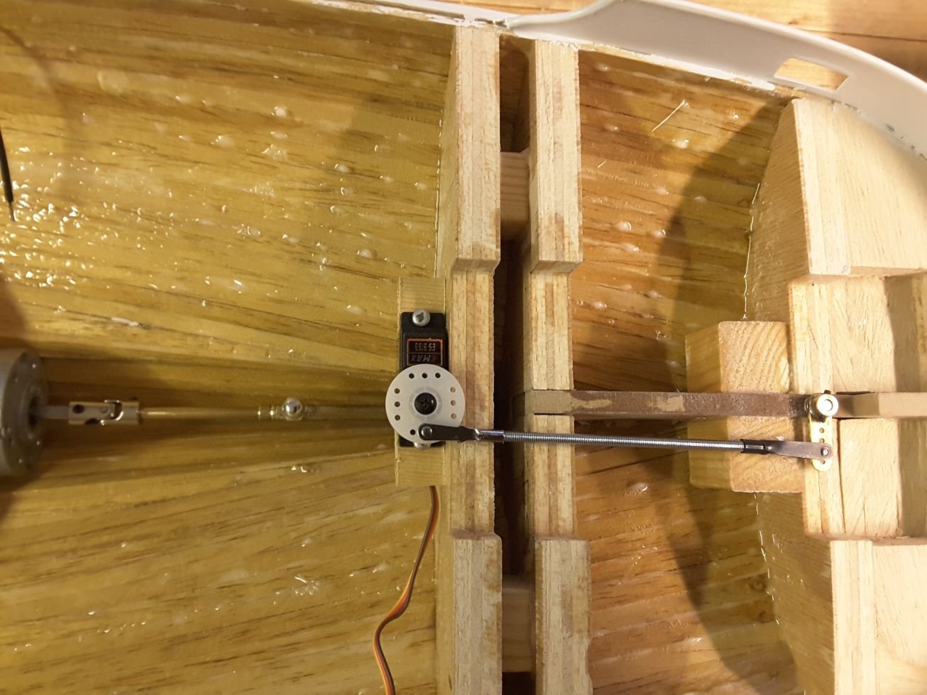
Now, when no deck has been built yet, it is very easy to install brackets for rc equipment, like drive motor, propshaft, steering servo, battery, etc.
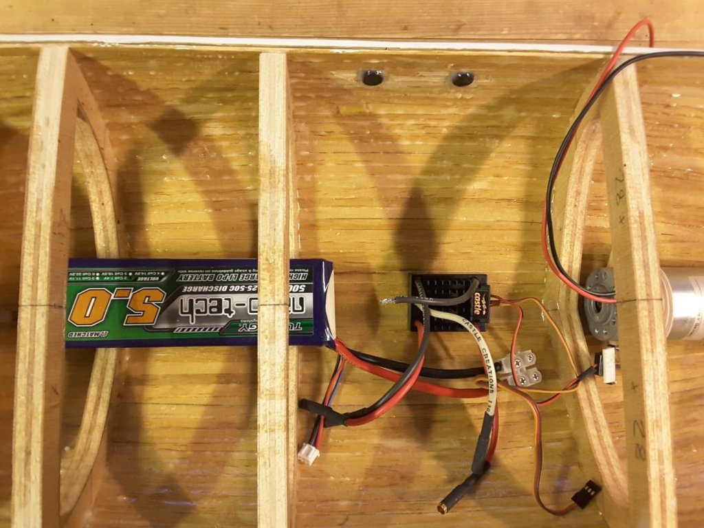
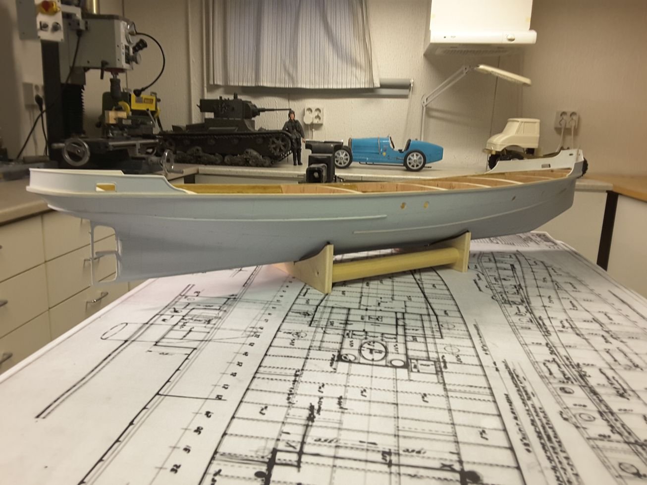
Because the draught of this model is reasonably small due to shallow lake waters where the ship has been used, no heavy equipment like lead batteries could be used. This is why I selected a 2 cell 7,4 volt 5,0 Ah LiPo battery as the power source.
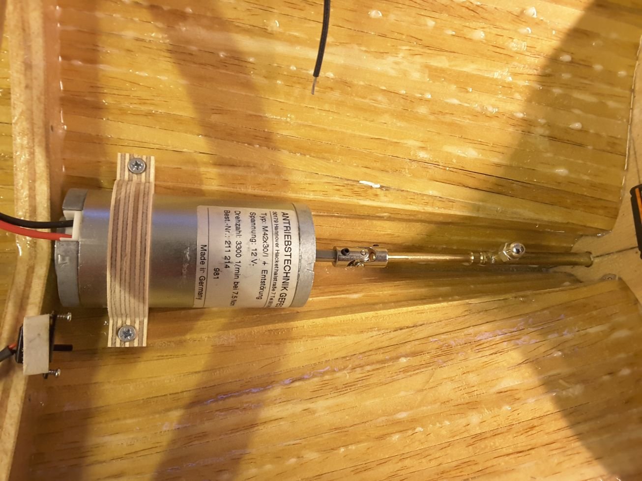
Very nice and silent electric motor made by German Gefeg was installed as a drive motor. It is a 12 VDC, 3300 1/min unit which fits nicely into the hull.
Speed controller is a programmable Sidewinder, made by Castle Creations. It was programmed for brushed motors, and both accelerate and braking curves were set linear.
Steering servo is a tiny taiwanese unit which is connected to the rudder arm by threaded rod. I hope it has torque enough to turn the rudder.
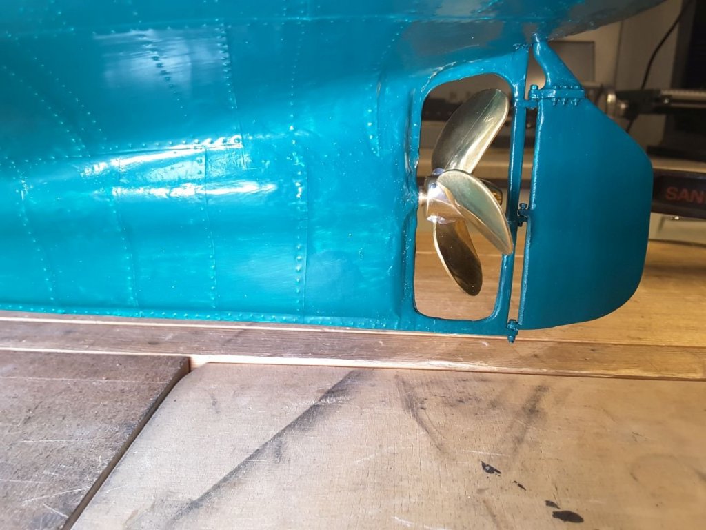
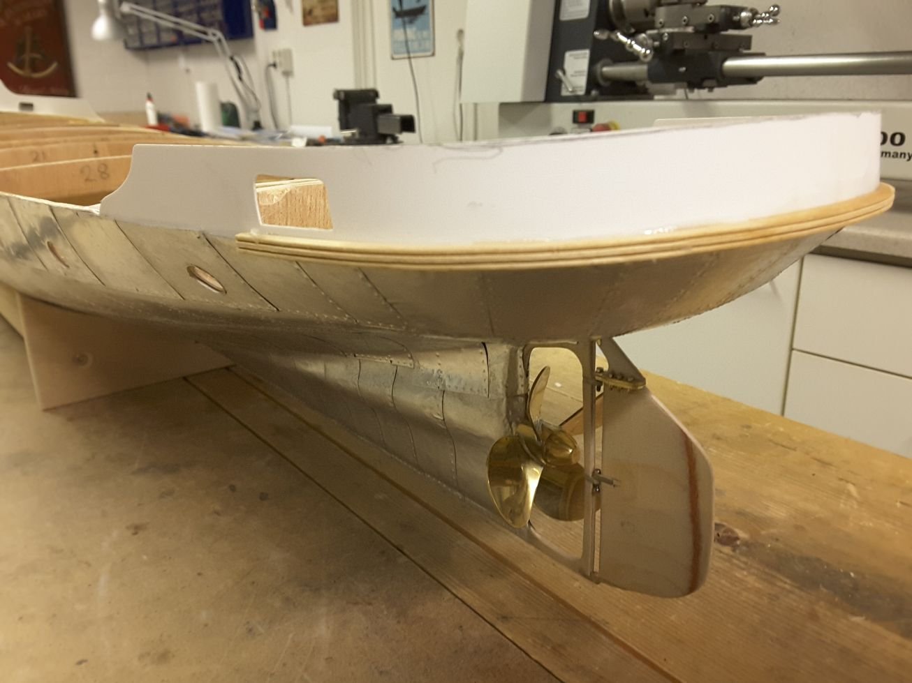
Propeller is a four bladed brass one with 60 mm diameter bought from Cornwall Model boats. And propshaft is a 4 mm diameter brass rod. It is running in a 5 mm ID brass tube, where bushes have been made at both ends. The tube has a small connection inside the hull, through which the tube will be filled with grease, to avoid water entering into the hull.
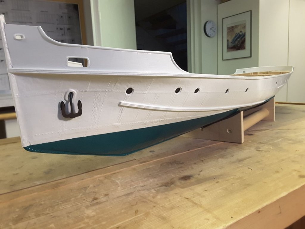
Rudder and propellor. Hull bottom colour looks a bit odd due to lighting. In normal light it is more like dark green.
Steering servo with connecting rod.

Motor and propeller shaft. Connection for grease filling can be seen at the top.
Battery and speed controller. A 2,4 GHz receiver will be located into superstructure to have better connection to transmitter.
- mtaylor, Rudolf, John Allen and 9 others
-
 12
12
-
Might be. I could ask the paint shop about the details of the paint they are using.
- Stimpy, Mirabell61 and mtaylor
-
3
-
Hello Nils, the primer provided very nice matte surface where final white paint bonded very easily and tightly. Until today I have not experienced any loosening of the primer, and I have a feeling that it sits very tightly on aluminium, so I think that was a perfect solution for this case.
- mtaylor and Mirabell61
-
2
-
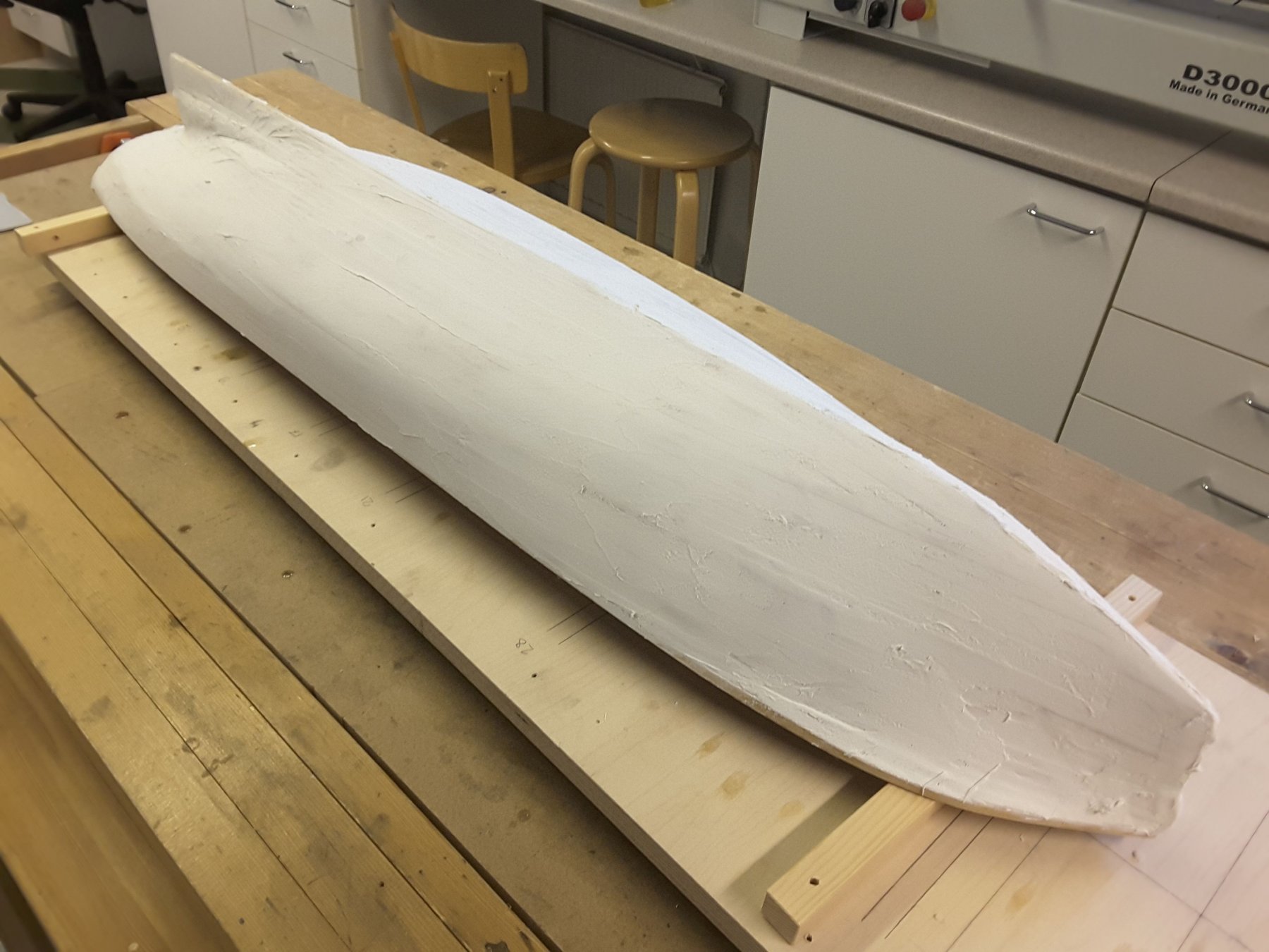
Next I took the hull to a car painting shop, where they sprayed a nice grey acid primer to the surface.
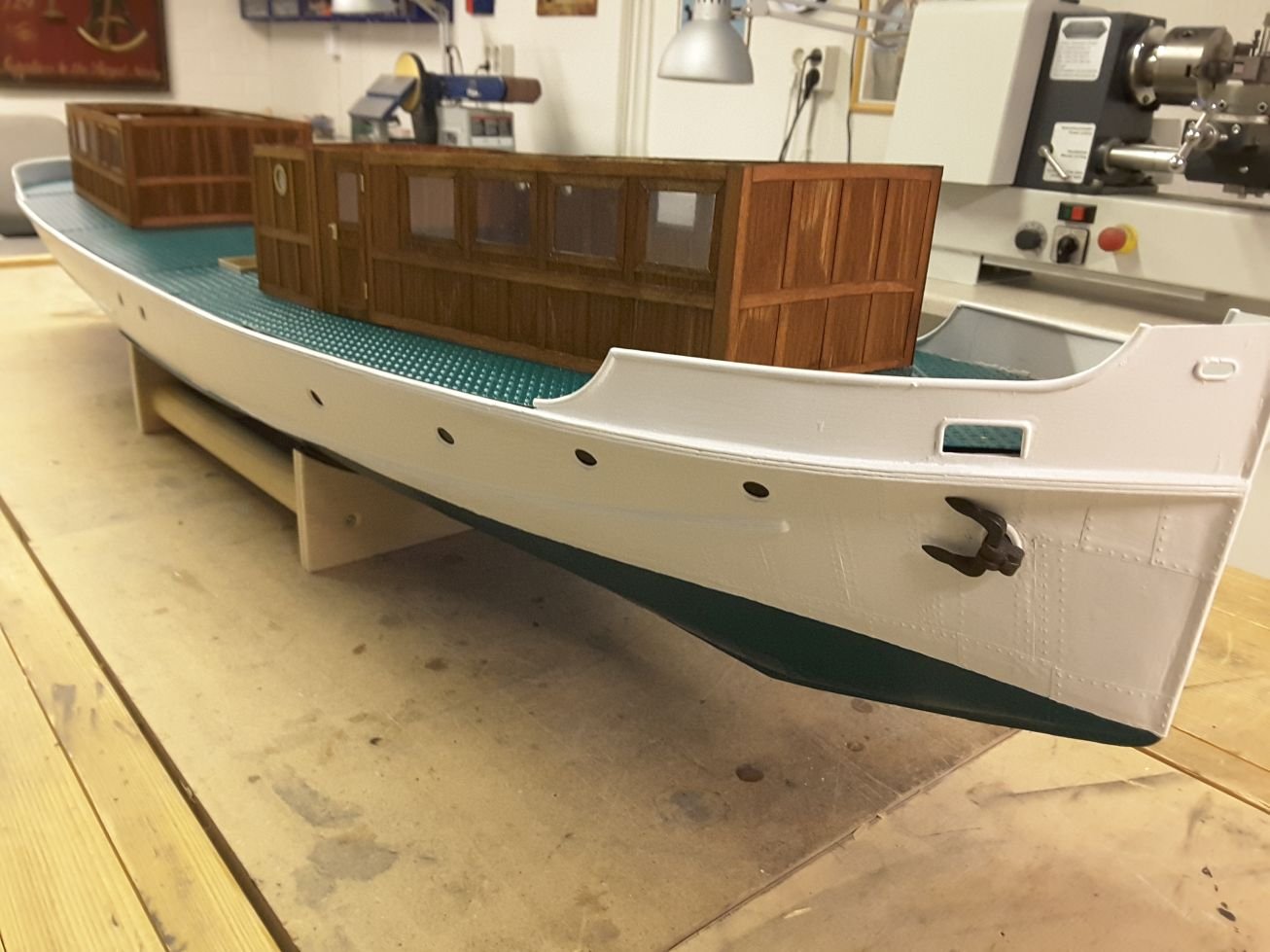
And after that I brushed white half matte water soluble paint on it. Waterline was marked with a fixture like this, and a masking tape was applied to separate dark green bottom paint from the white.

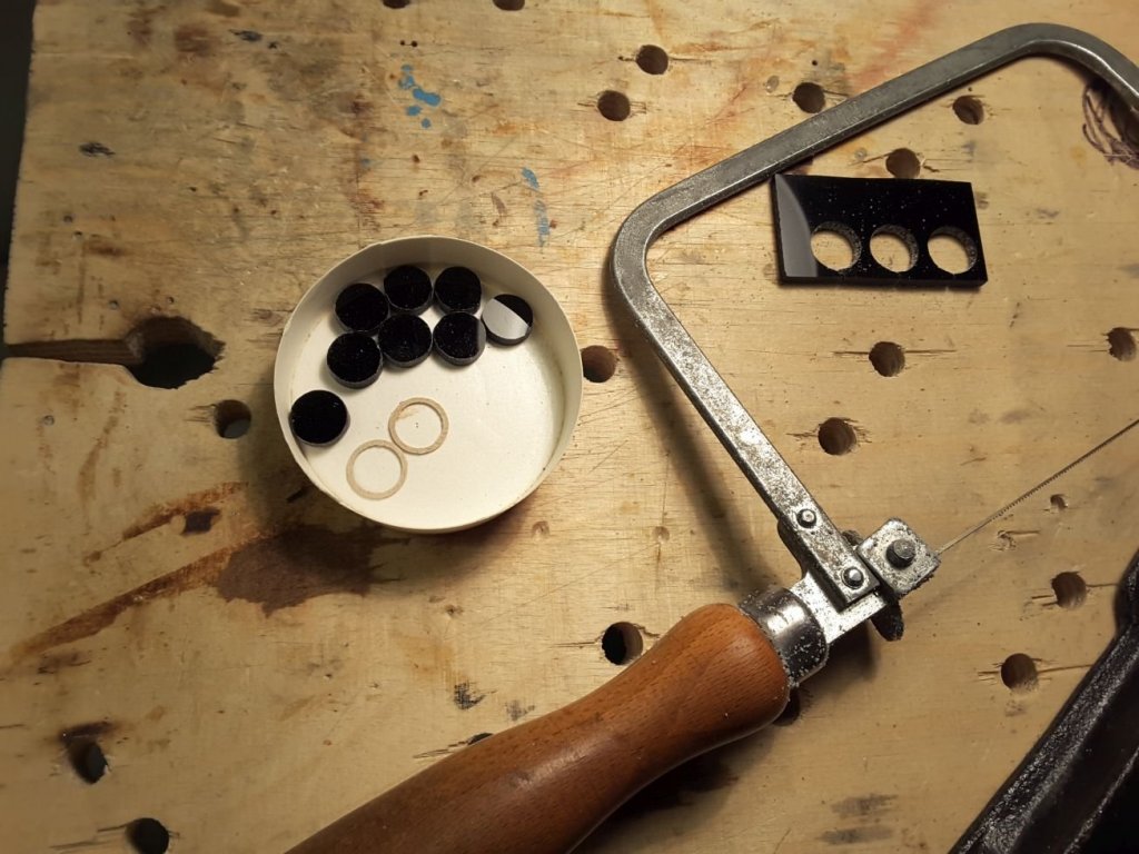
Anchors (Cornwall Model Boats) and windows were attached next. Holes for windows were first drilled with 10 mm drill bit. After that 10/9 mm rings were cut of 0,8 mm plywood with a cnc machine and glued into the holes, and finally 10 mm diameter window glasses were sawn of 3 mm thick black acryl sheet and glued inside.
Hull painted and anchors & cabin window glasses installed, waiting for next tasks.
-
Thank you Nils. I am very happy that you like my work.
The rudder construction is made of brass. Parts are soldered together and the form at the lower part of rudder shaft is made using epoxy/microball putty. Flanges are bolted together with M1 bolts and nuts.
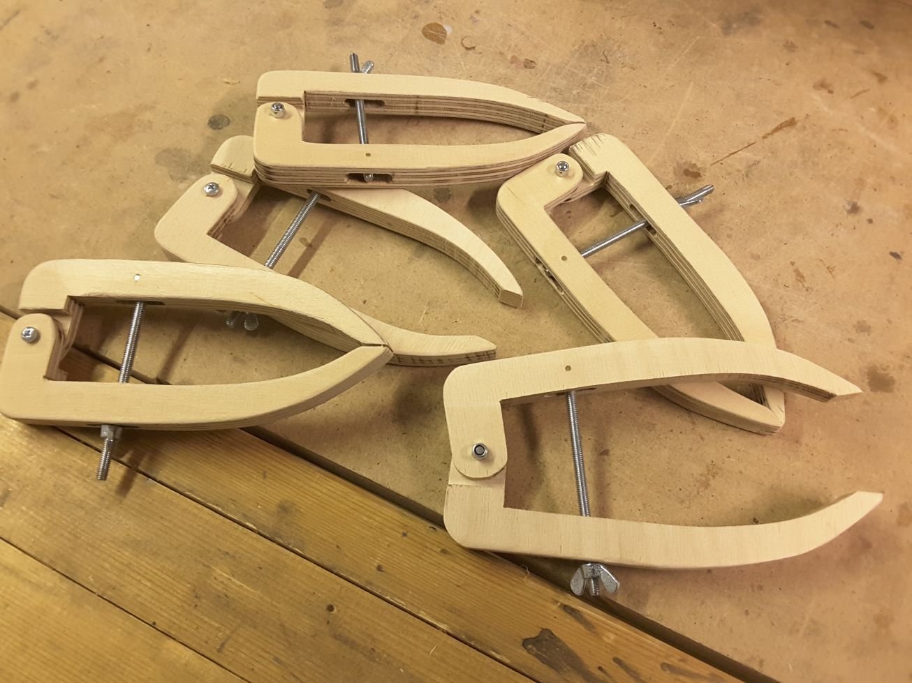
And those long leg clamps are marvellous. Very often I am in the situation that normal clamps have too short legs.
- Mirabell61, John Allen and mtaylor
-
3
-
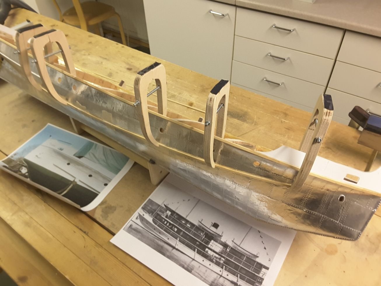
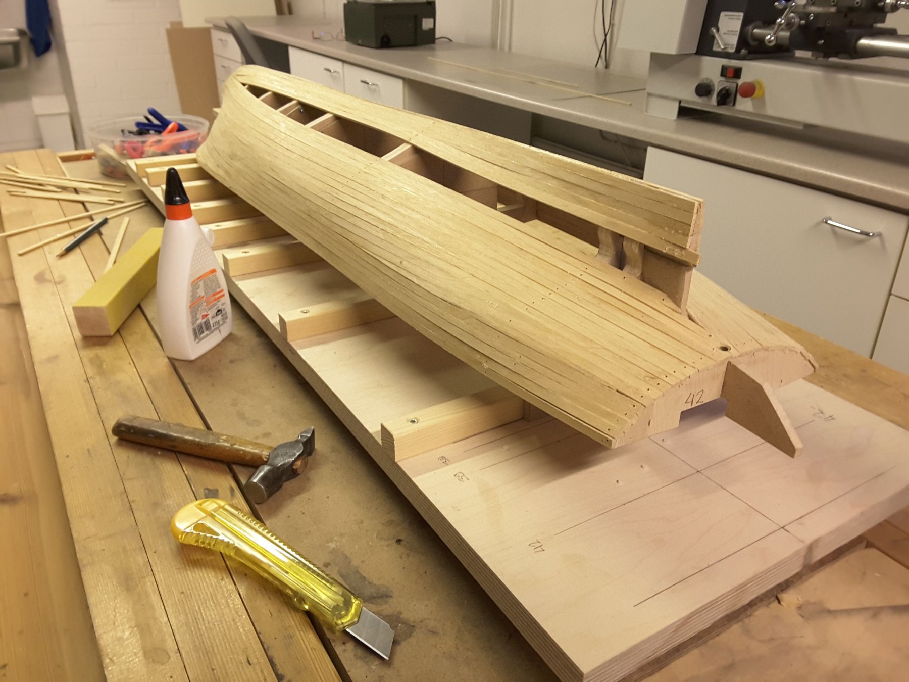
Next I started to think about all the different lists outside the hull. Old iron ships had many different profiled lists on the hull, and so did this too. There are round, half round and more complex grooved lists to be installed. The first two are easy, just go to the nearest hobbyshop and buy styrene strips with right dimensions. The grooved ones were a bit more difficult. After having thought hard, how I could make them, I finally made a forming tool of an old window scraper, and used 3x4 mm abachi strips for material.

Form tool and strips made with it.

Form list glued at stern.

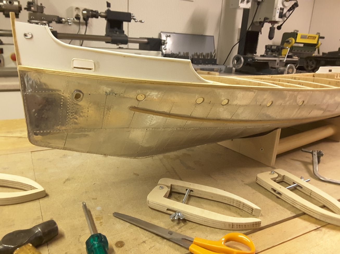
Those lists under the waterline were difficult to keep on place during glue curing. For this work I made some long nose clamps according to old shipwright manner.

But the first clamps were a bit shaky due to hinge made of leather. These improved ones work much better and are easier to use.

And finally all the lists and window frames are installed and the hull could be taken for painting.
- steamschooner, oneslim, mtaylor and 15 others
-
18
-
Hi Nils, Roger and Michael, thanks for your postings. It is always very nice to see that people like my building.
Roger: Because the foil is very soft and easy to bend, after applying glue I just pressed it tight against hull with my fingers and it stayed there. It keeps so tight that it is very difficult to tear away if that would be necessary. However it is possible to slide it carefully on the surface to different position if you have to correct it. This is a good feature, because with contact glue it is impossible.
Michael: Of course I am not working so fast. I just started the blog when I was sure that I can manage the plating. So now we are about in real time and updates are beginning to appear slower.
- John Allen, mtaylor and Mirabell61
-
3
-
Thanks Nils, John Allen and steamschooner. Your comments give me lot of motivation to continue!
Yes I am going to paint the hull because original was white. I have thought to use acid primer for the first treatment, and satin white on that. Both sprayed perhaps by some professional car painting company.
Thicker foil might be better, since it would not show all the faults on the hull surface so badly as this one. But on the other hand I was trying 0.13 mm offset foil in the beginning, and it was too stiff. But there are all kinds of foils available, maybe softer 0.1 mm would be the best option.
- John Allen, Mirabell61, tarbrush and 1 other
-
4
-
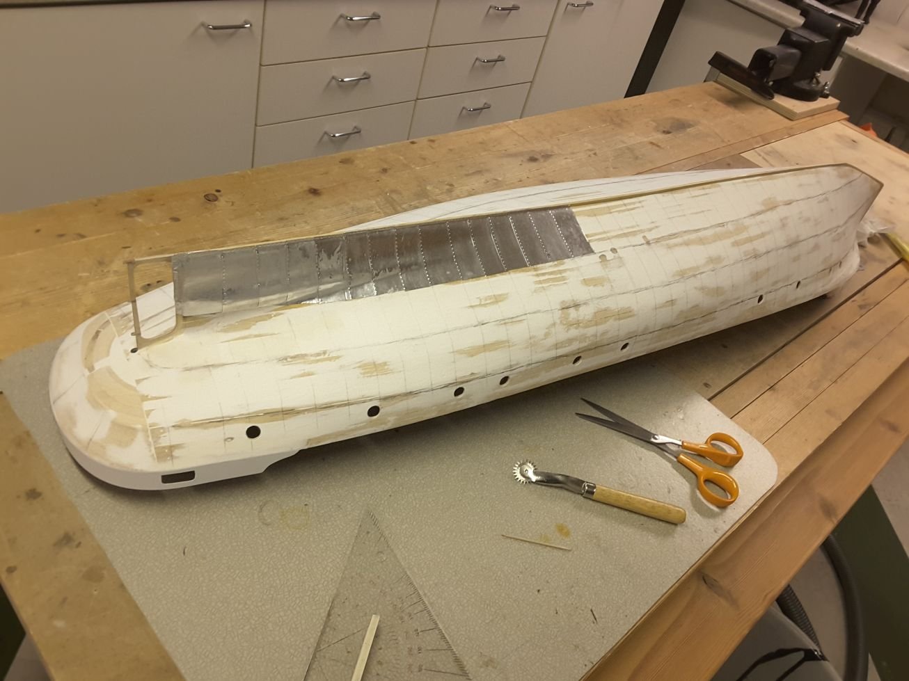
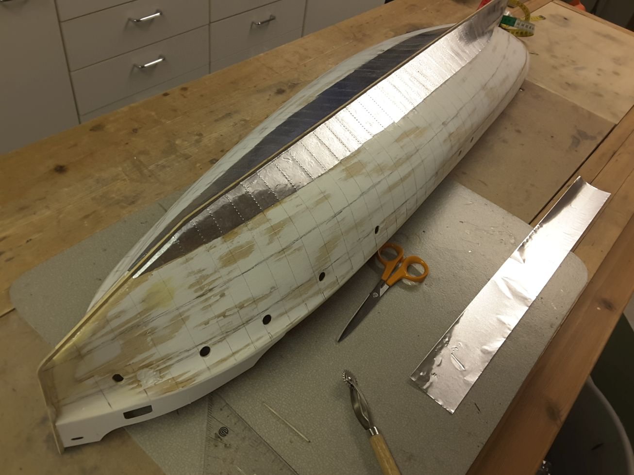
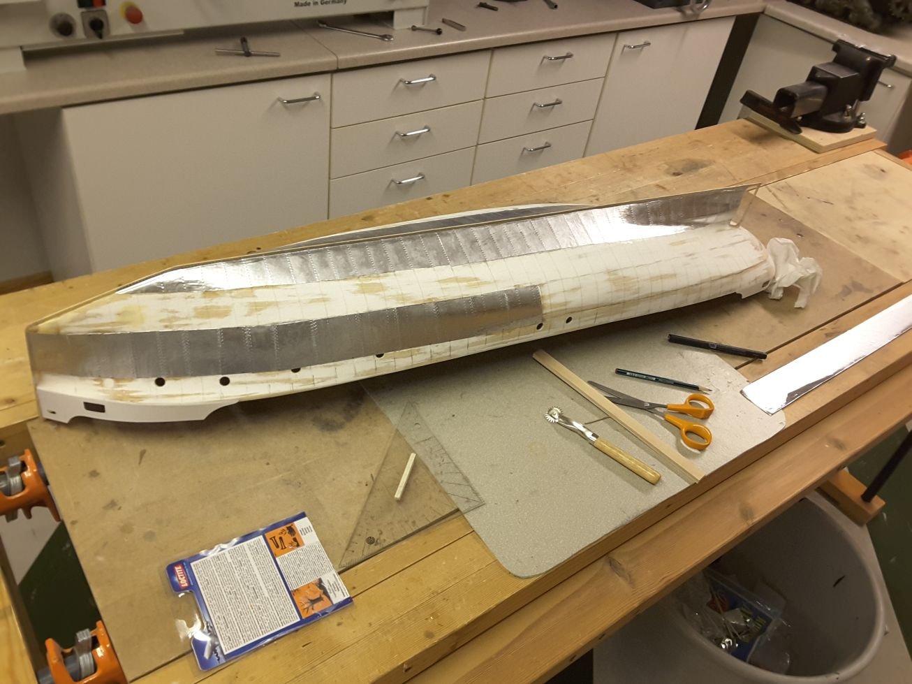
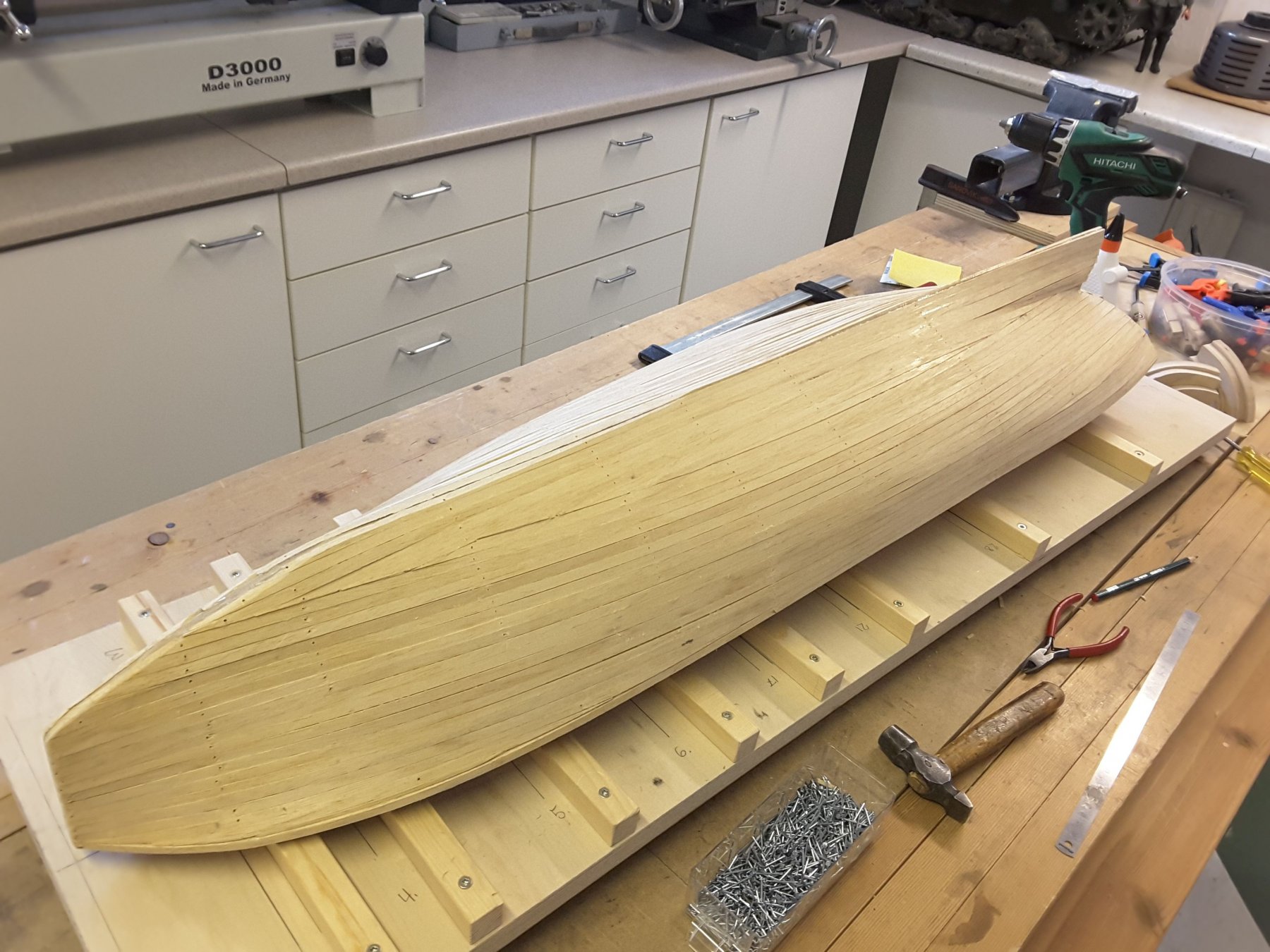
With a big excitement I finally started the plating work. As I said earlier, this is quite new for me because I had never done this work before. First I was trying different glues into some scrap wood, and realised that contact glue is not suitable for this work, because if you apply glue on both surfaces, then let them dry, and only then apply them into hull, it must be right at the first time. Not possible to adjust the location of the plate any more. So this is why I selected slowly (4 hours) curing epoxy to be my glue.

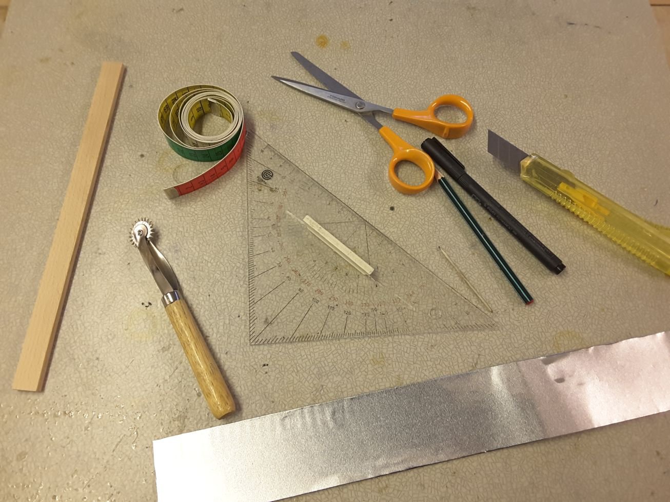
Tools for the work. Very useful are a flexible measuring tape and especially the toothed wheel to make the rivetings. Those two were found at admiral`s sewing box. At front is a 50 mm wide belt cut from a reel of 0,05 mm thick aluminum foil.

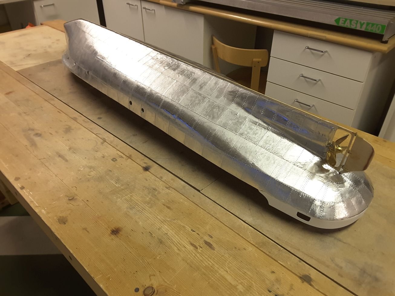
First plates glued. They bend very nicely at one direction, but not so good into the second. But all the hulls of old iron ships that I have seen are like a surface of a potatoe bag, so no worry. It might have been better to choose 0,1 mm foil instead of this thinner one, but here we go.
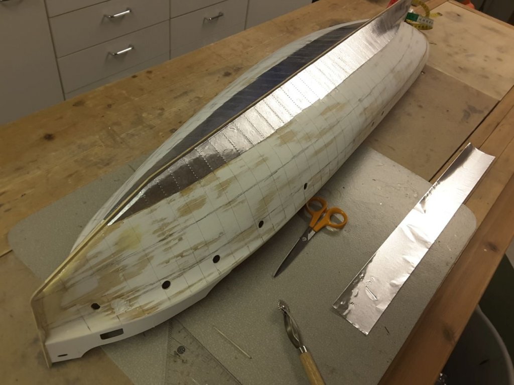
Lowest belts done on both sides.
When I studied the old photographs I noticed that the second belt from above was under the neighboring ones, so this is why I made that as next.

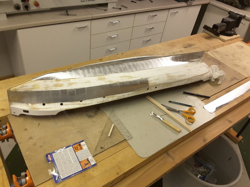
And after a few day`s work the whole hull was plated. Not so good as the old masters did 100 years ago, but enough for me. In the mean time I made the rudder and checked that there was enough room for the propeller which is 60 mm diameter and bought from Cornwall Model Boats.
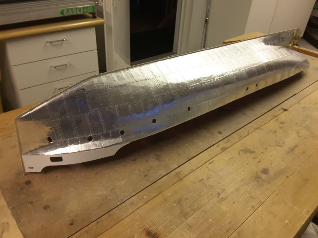
The openings for cabin windows were also done after the glue had cured.
-
Very nice work indeed Nils. I wonder where you have found those scale figures (1/48) When I was searching them for my last project I couldn't find any.
- Mirabell61, Omega1234 and mtaylor
-
3
-
Hello Nils and thank you for your kind comment.
And yes, the hull is quite roomy. But the draught of these lake steamers is very small due to low waters, so there is not much possibilities to add heavy equipment like lead battery etc. So I must use LiPo or equal.
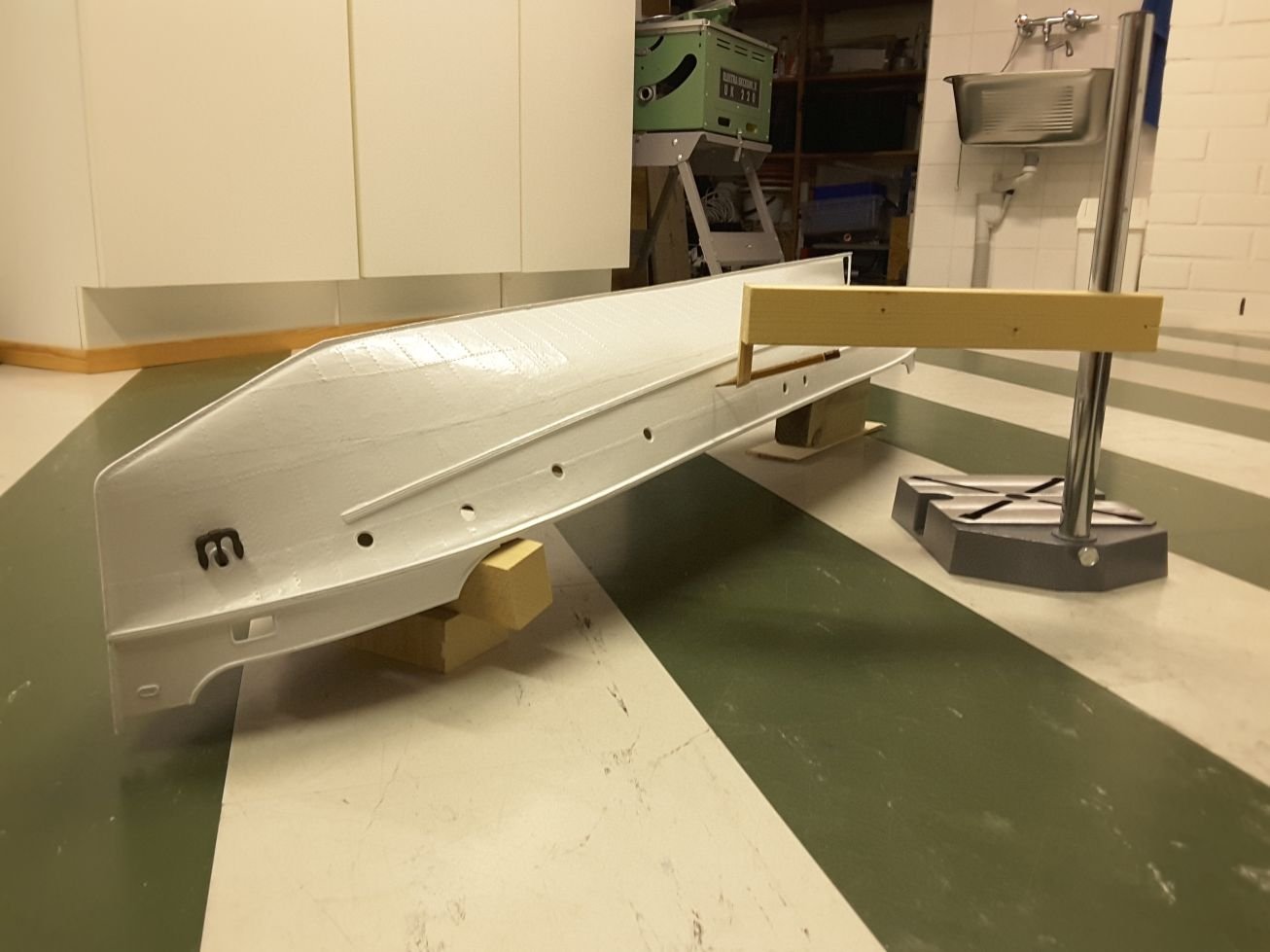
Also the superstructure of this ship is reasonably high compared to that of the hull, so it must be built very lightly in order not to add too much weight there.
- steamschooner, mtaylor and Mirabell61
-
3
-
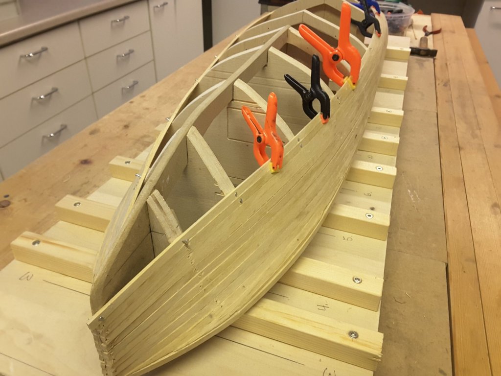
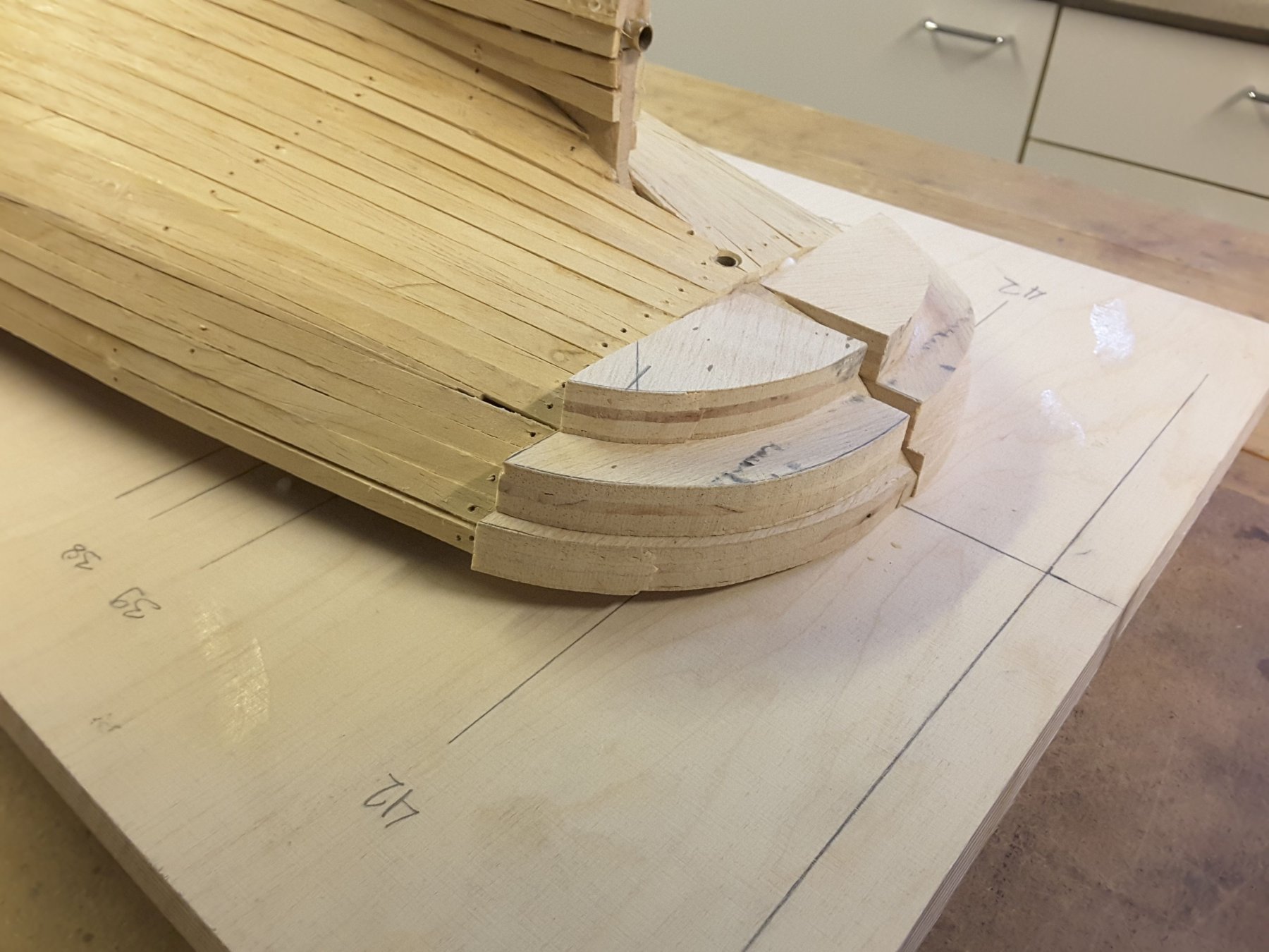
After planking the hull, round form of stern was made using balsa plywood again. The more I use this material, the more I like it. Light, strong and very easy to saw and sand.
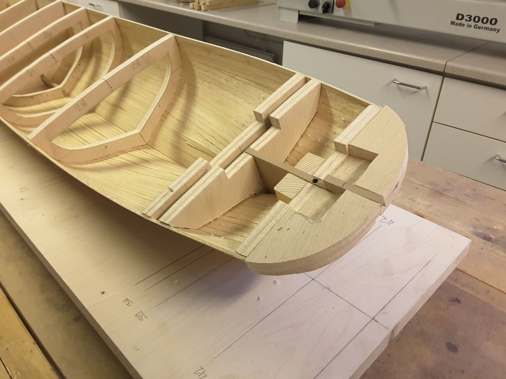
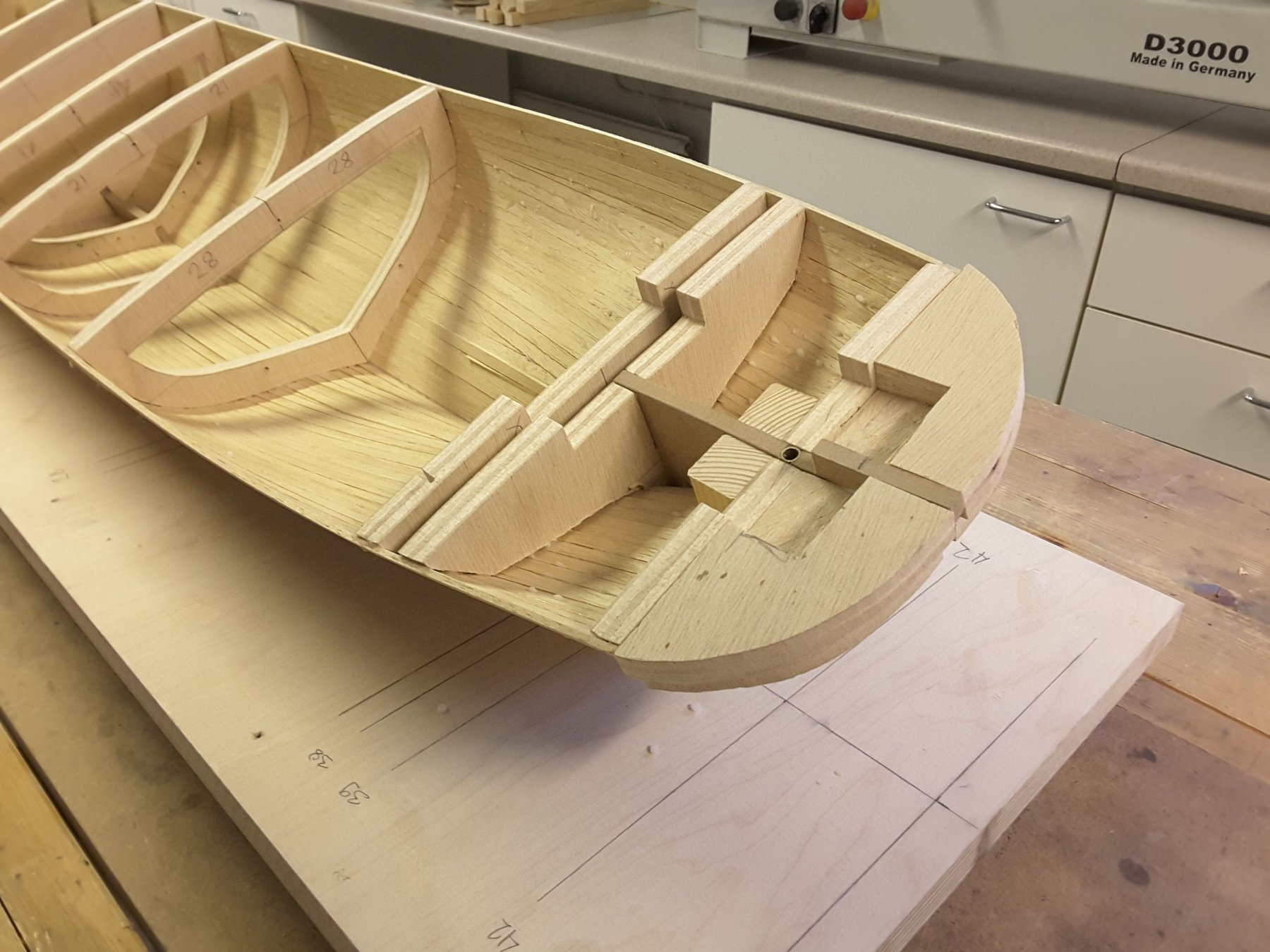
Inside of the hull. 5 mm brass tubes inserted for rudder & propeller shaft.

To make the hull stronger and watertight I treated inside with stuff mixed of epoxy resin and milled glassfibre.
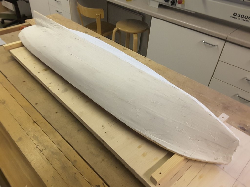
And outside was filled with epoxy/microballons.
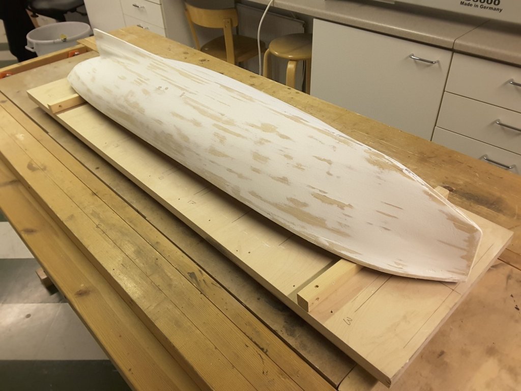
After filling/sanding the hull starts to look correct.
And finally, after a few day`s work hull was smooth enough for starting the plating work.
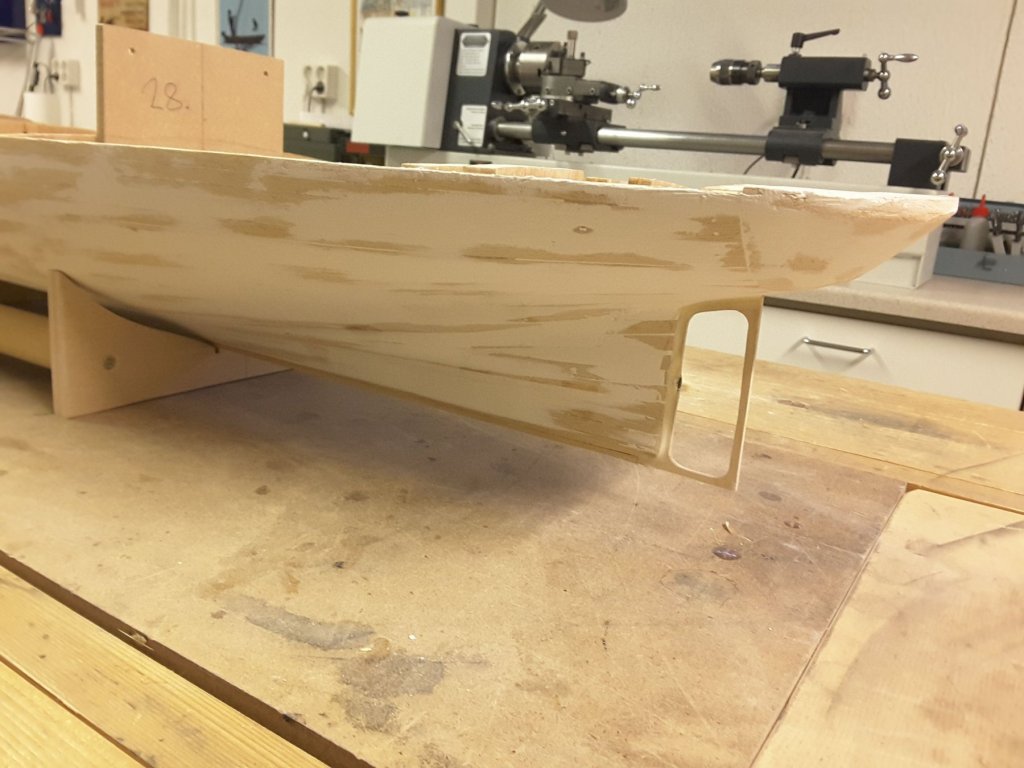
Frame for rudder was made of 2,5 mm aircraft quality birch plywood.
-
-
Thanks Nils for your kind words! The alufoil I bought is not self adhesive. I thought to glue it using epoxy or perhaps contact glue. Aeromodellers are using contact glue, but it is a bit messy, and after having spread it on both surfaces and let dry, you have just one possibility to attach it into hull. Correction of position is no more possible. For this reason I think I will use epoxy.
- Mirabell61 and mtaylor
-
2
-
Very nice project and marvellous craftmanship Nils. It is a pity that I have not followed this thread until now. But from this moment onwards I will for sure!
- mtaylor, Piet, popeye the sailor and 2 others
-
5
-
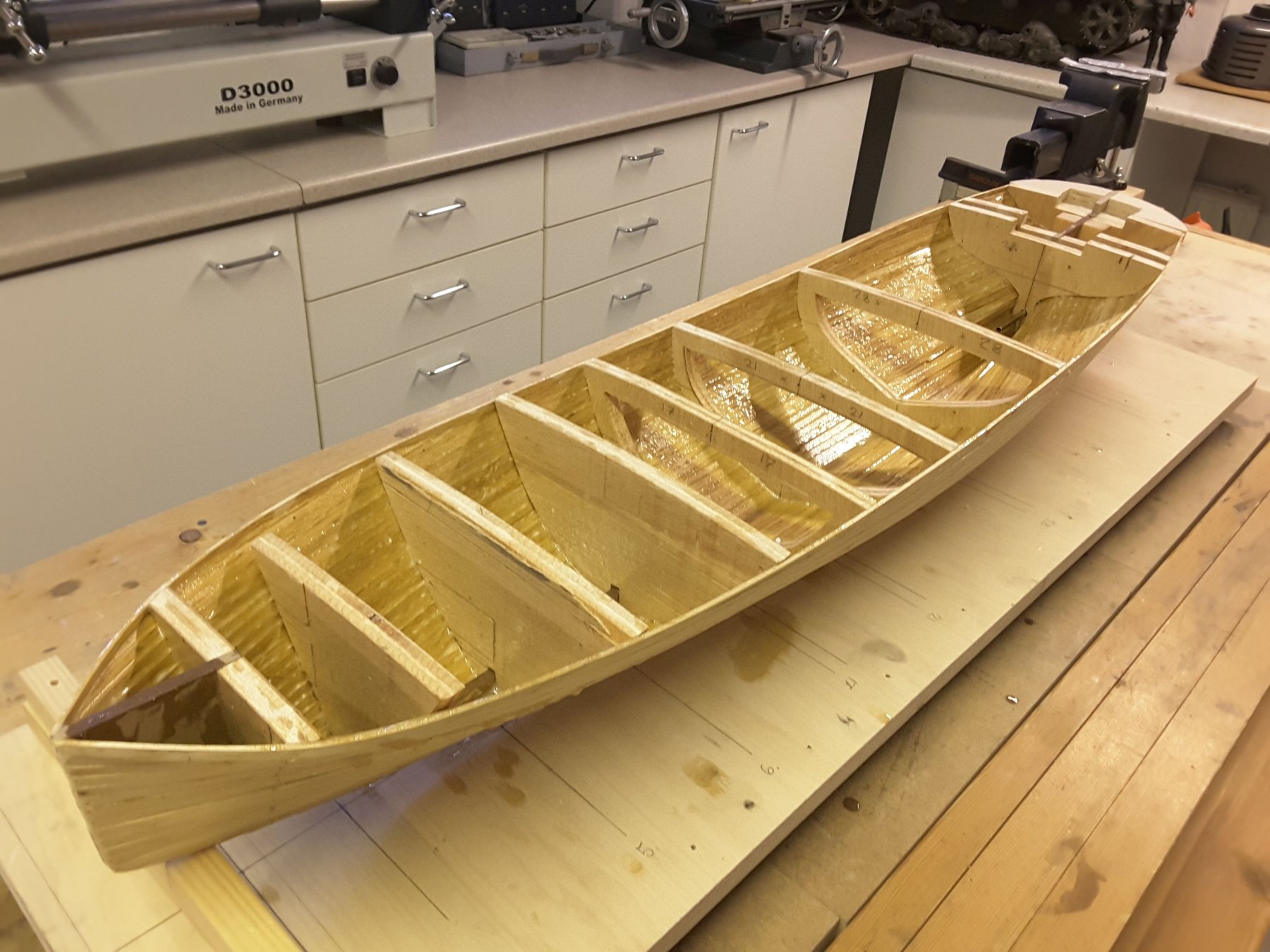
To start with planking I was cutting 2x6 mm strips of abachi wood with my Proxxon table saw. That went without problems, so the work could start. Because my intention was to cover the hull with alufoil, there was no reason to avoid any nailholes or other blemishes, so the work continued fast. After planking I was filling all the holes with a putty mixed of microballons and epoxy resin. Benefit of this stuff is, that you can mix it as solid or fluent as you wish, and when cured, it is very easy to sand.
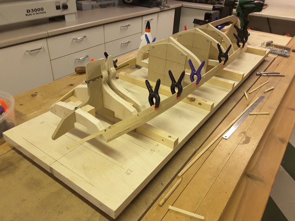
First planks glued.
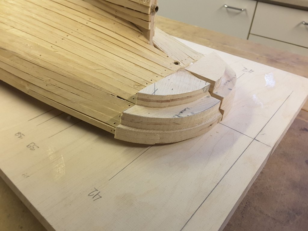
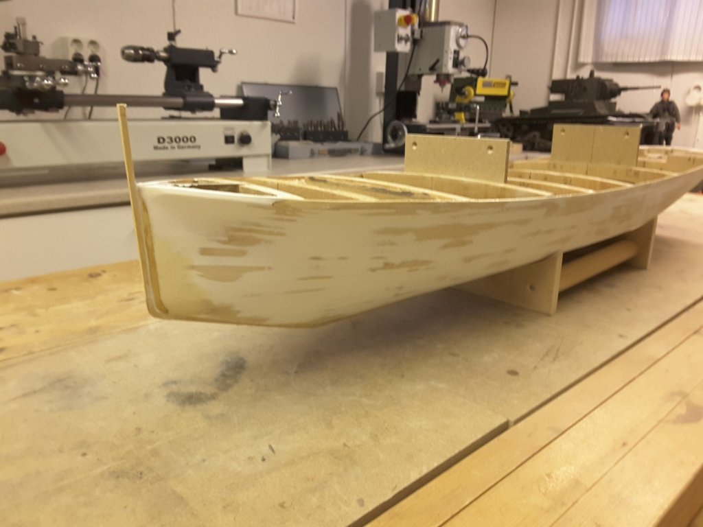
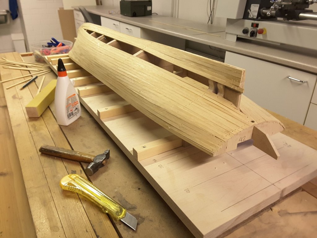
At this moment I found out that the hull didn`t follow the lines of drawing, but started to go wider. So new bulkheads were needed. Cardboard models were adjusted first, and when ready final bulkheads were cut of balsa plywood. Three more bulkheads cured the problem, and planking could continue.
Almost there. At this moment I started to think, which kind of alufoil should be used for plating the hull. Normal kitchen foil was much too thin, and the aluminum plate used by offset printing companies (the one that is used by aeromodellers) was too rigid, even when I tried to anneal it with a flame torch. After searching from Internet, very promising 0,05 mm thick foil was found from an Hungarian company ( https://www.aluxfoil.hu/webshop/ipari-alufolia/alufólia-50-my-x-1000-mm-x-25-m-detail.html ) and a roll of this was ordered.

Finally ready with planking, so filling and sanding could be started.
-
Thanks Nils, I am glad you like my first posting considering this build. I hope you find it interesting when we get a little further with building.
- mtaylor and Mirabell61
-
2
-
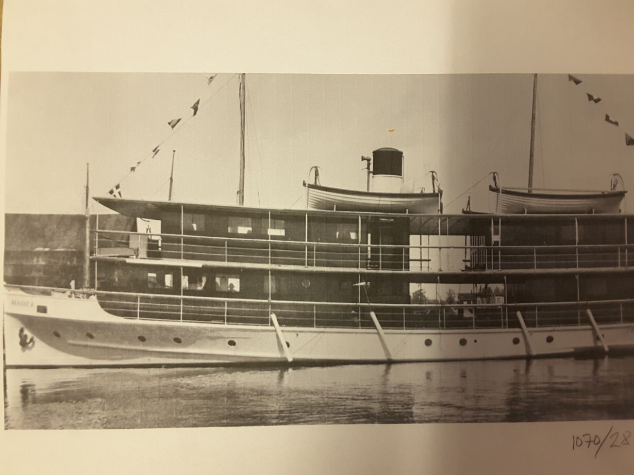
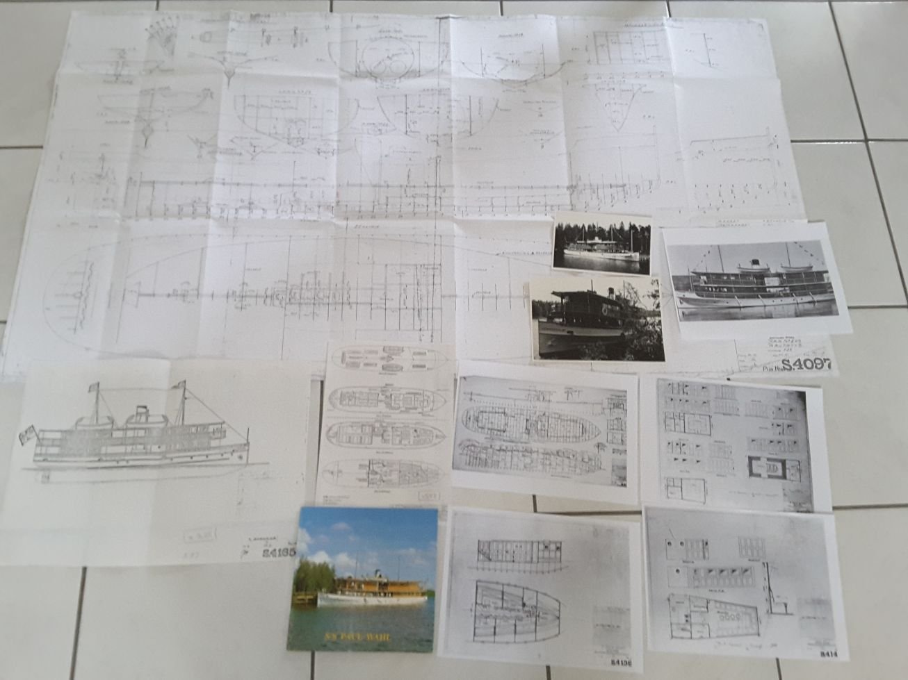
After my latest build, the French cutter Le Cerf, I was looking for a new project. Otherwise my days as a retired old chap would have been too long. Luckily I happened to find out that the formerly skipper of the lake steamer S/S Maaninka was about to give up his original drawings of the ship. His idea had been to make a model of the ship, but due to his high age decided not to do so, and was searching a good home for his drawings and someone who would make the model of her. Well, I promised to try that, and here we are.
The ship in question is a lake steamer, built in Varkaus Finland on 1919 at the Ahlström mechanical works. This shipyard was a famous one in the country having made ships from 1862 until 1964, making well more than 800 different vessels, and the ship in question was the number 547. As already stated, the ship was made during 1918...1919, and was named S/S Maaninka. She was made of iron with a riveted hull, the overall length being 87´ and beam 20´ , and was equipped with a two cylinder compound steam engine. Since this date the ship has changed it`s name many times, her present name being S/S Paul Wahl, and situated in the harbour of the city Savonlinna. This summer we were lucky enough to attend to a short cruise on the ship and take several photographs of the details on board, in order to help the building of the model.
I was thinking to make a working model of her with a radio control and equipment like sound generator and smoke generator, and use the normal plank-on-bulkhead method, but cover the hull with some sort of aluminum foil to represent the rivetings. Plating the wooden hull with foil is quite new method for me having never tried that, but aeroplane modellers have used this method when building large scale models. So in the future we will see how it works.

Original picture of S/S Maaninka

Original drawing & other documents. Based on these the model must be made.

Measurements made and first ideas thought.
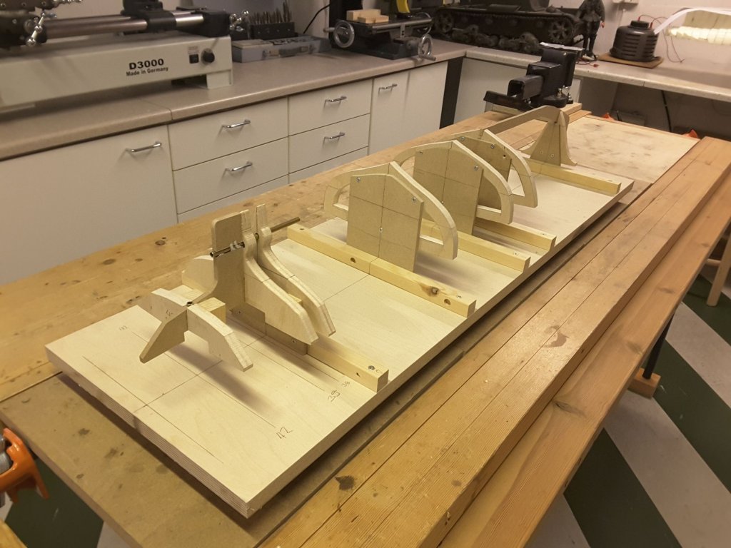
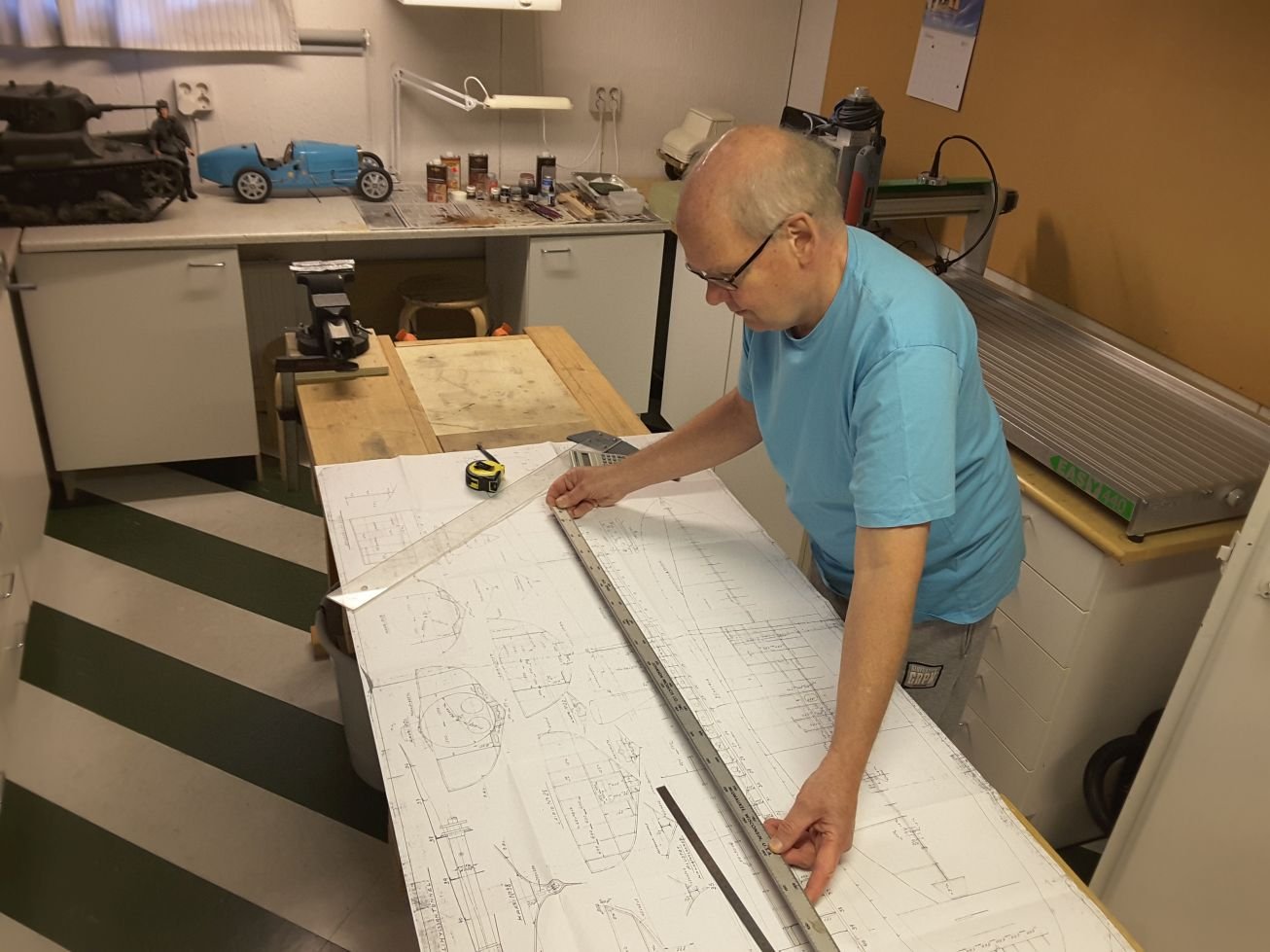
20 mm thick plywood was selected as a platform for the build. Unfortunately this was not straight enough so it had to be straightened by screwing two angle irons below. The original drawing included only 7 bulkheads. Those were sawn from 12 mm thick balsa plywood and attached into platform. Future will tell if they are enough, or should there be more in order to keep the correct lines of the hull.
Drag files here to attach, or choose files...
Insert other media
Uploaded Images
20171122_081347.jpg
125.05 kB
-
No comments about mistakes but about wonderful craftmanship. Very clever lathe to make belaying pins.
- aviaamator, PeteB and mtaylor
-
3


Eagle of Algier 1753 by Mirabell61 - FINISHED - 1:48 - Chebec - Nils Langemann
in - Build logs for subjects built 1751 - 1800
Posted
Nils, your build is progressing wonderfully and I really like your work and all the clever details and decorations. During the building I have noticed that there are many gratings throughout the ship. But how do you make those gratings, because every time I have tried to make them I didn't quite have success with them.