G.L.
-
Posts
1,553 -
Joined
-
Last visited
Content Type
Profiles
Forums
Gallery
Events
Everything posted by G.L.
-
 I don't know if I used the correct English term for it. It is a kind of paste that you can spread out on the workpiece which has to be painted. When it is hardened it can be sanded to a smooth surface. Below you see the product that I used.
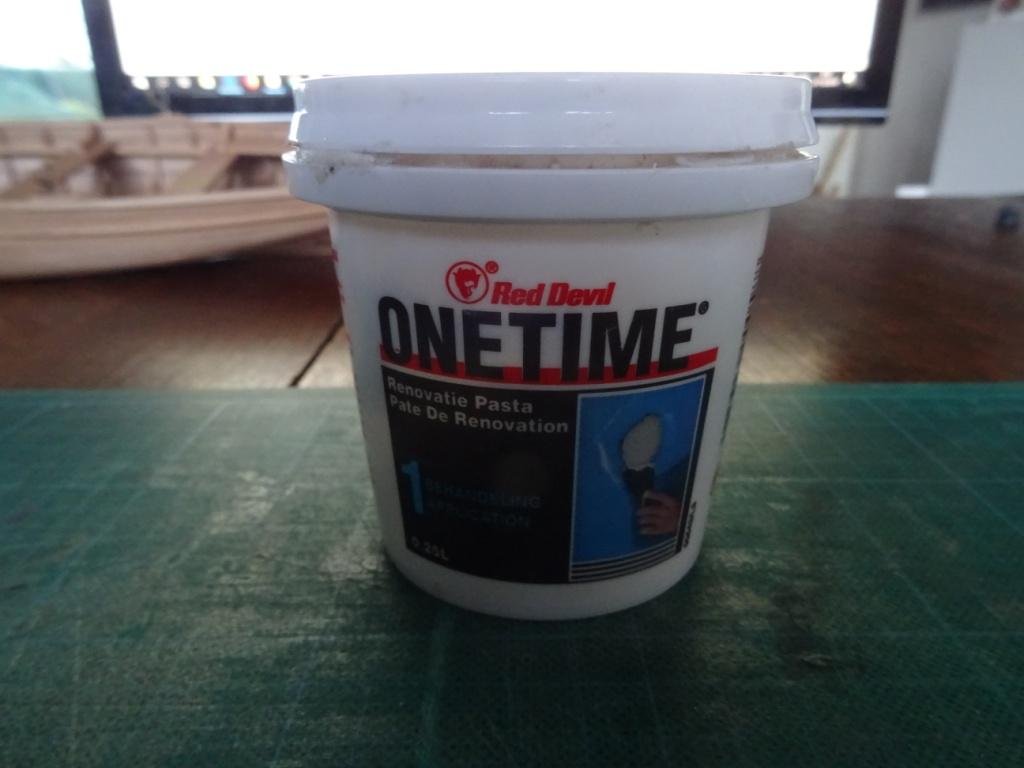
-
What a beautiful sewing machine, Peter. Sometimes you see old foot powered sewing machines in the thrift store, but in many cases they are in a questionable state. I believe I will have to learn the job with the sewing machine of my wife, she will be my teacher as well. Another option is that she sews the sails, but I am the modeler so I have to make the sails. When I am there you will certainly read about my befalls in my future posts.
-
Michel, I just signed in to follow your project. Bonne chance!
-
Keep courage, we thumb for you.
-
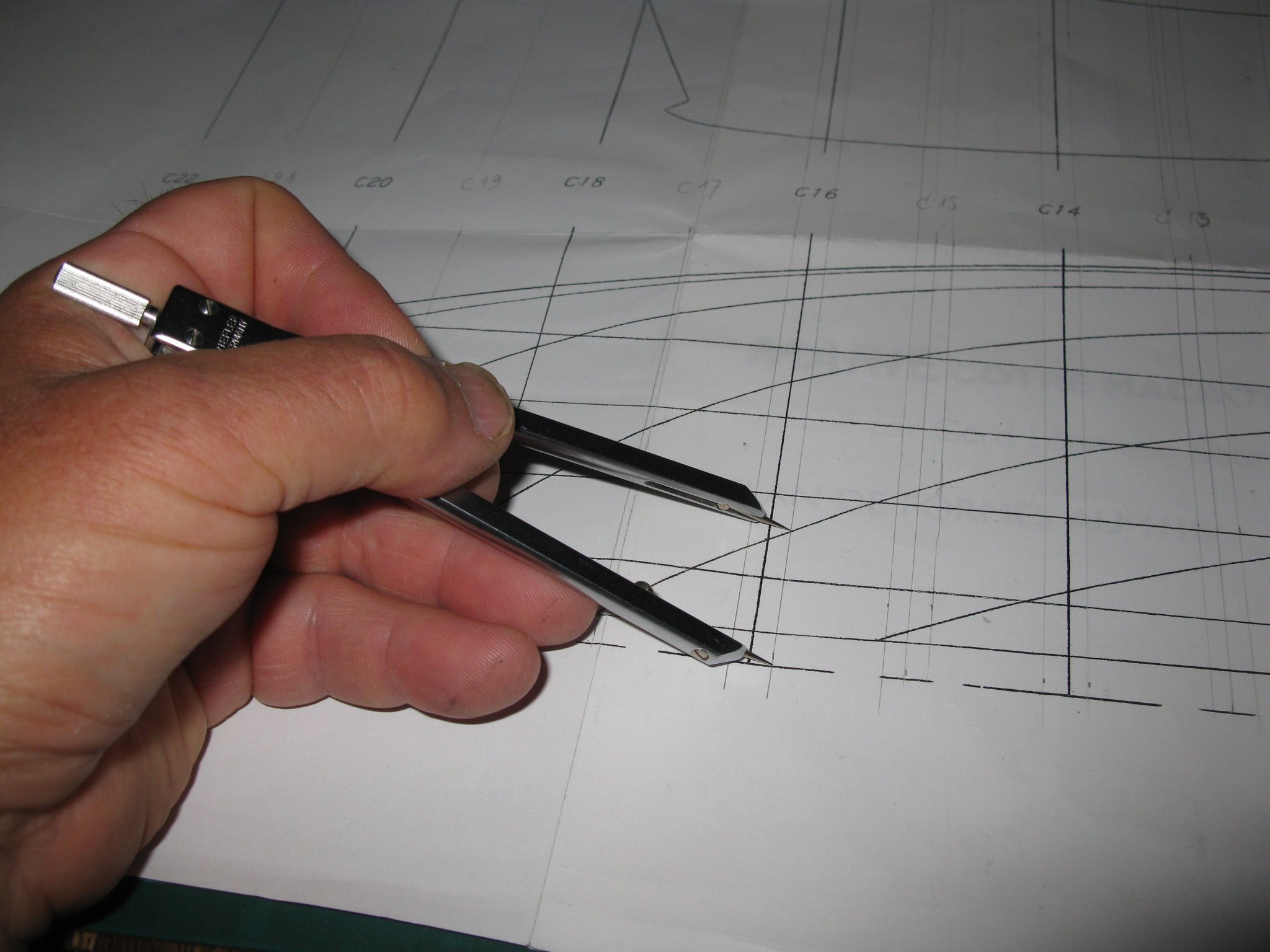
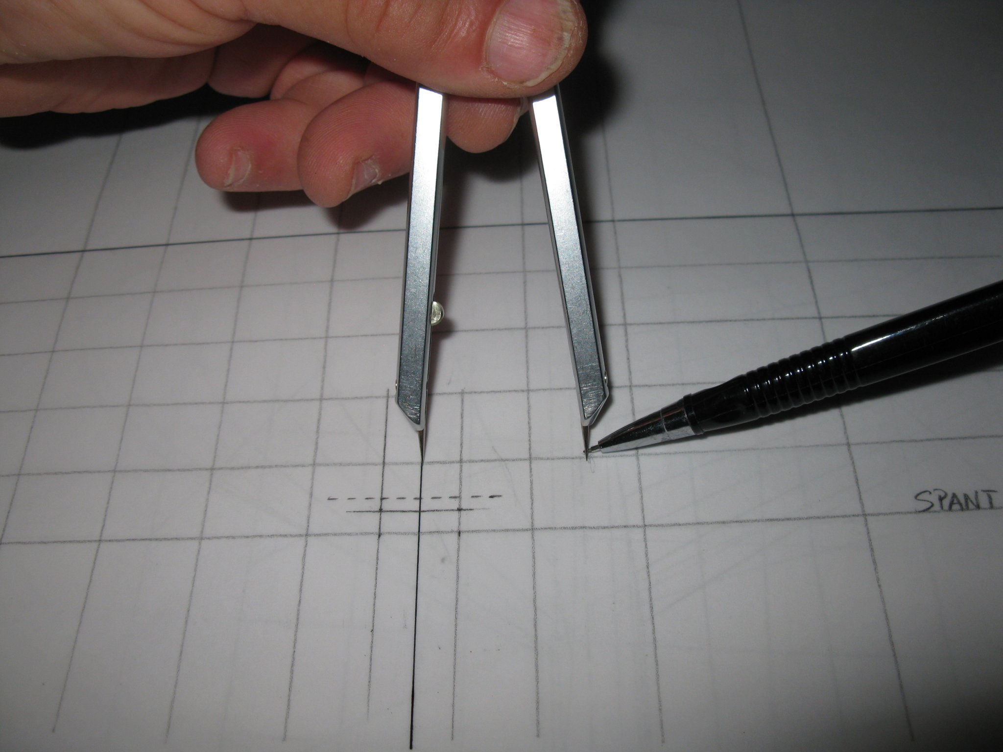
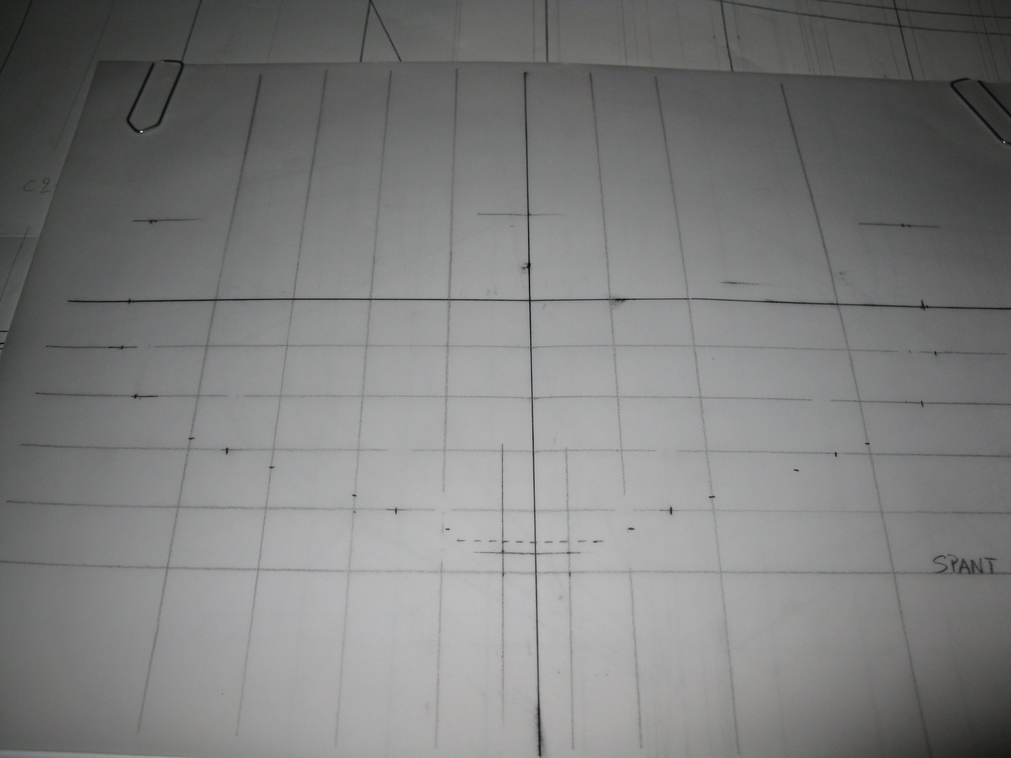
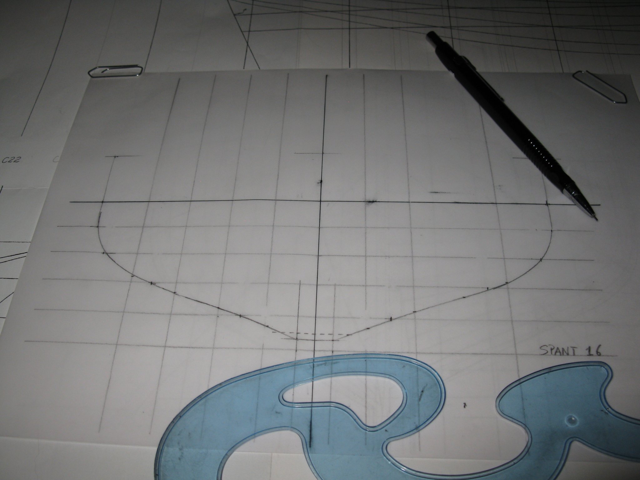
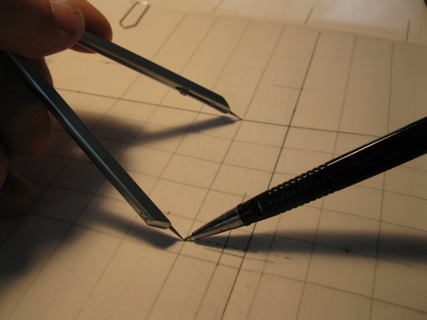
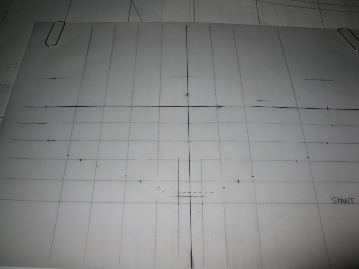
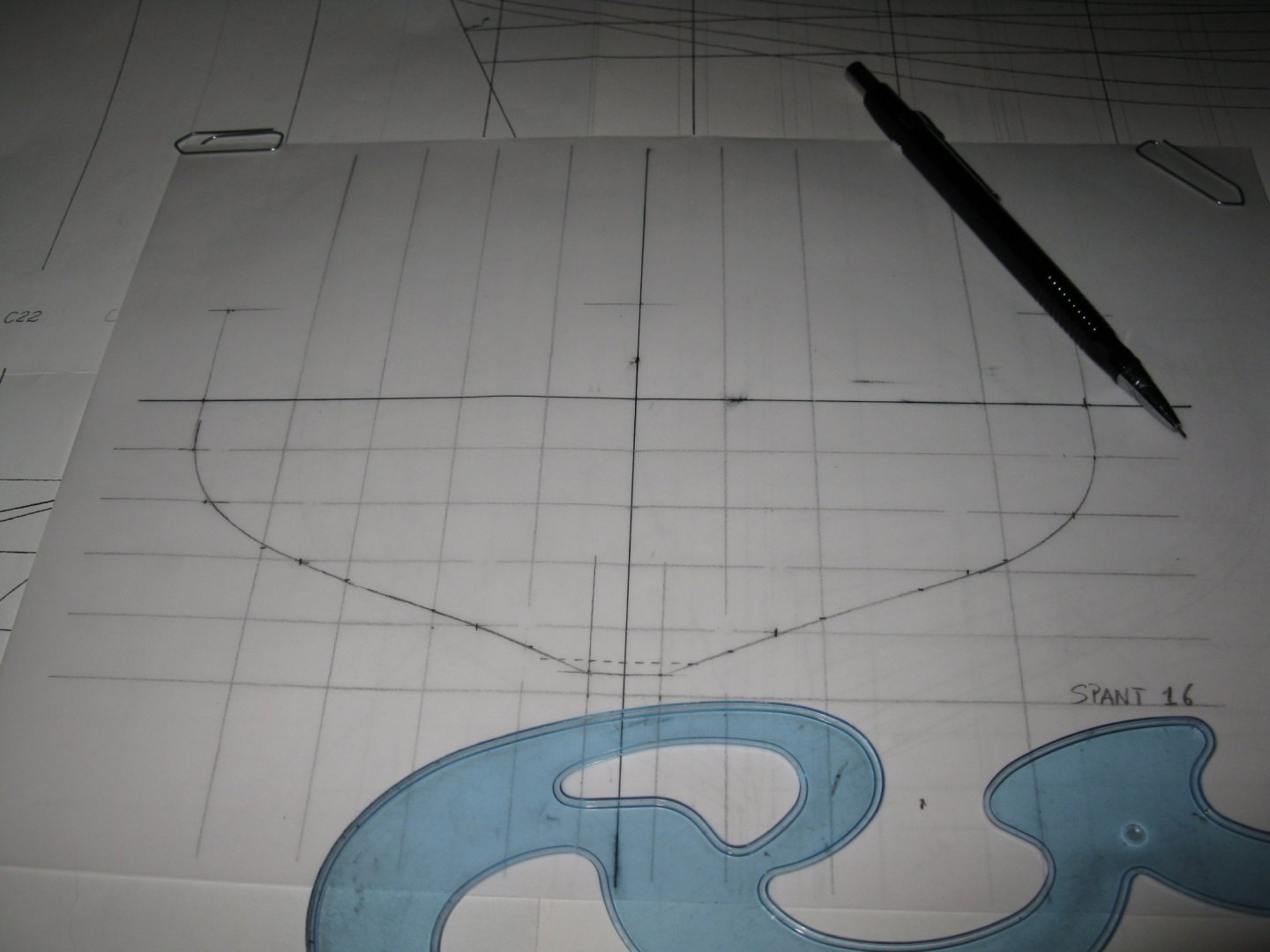
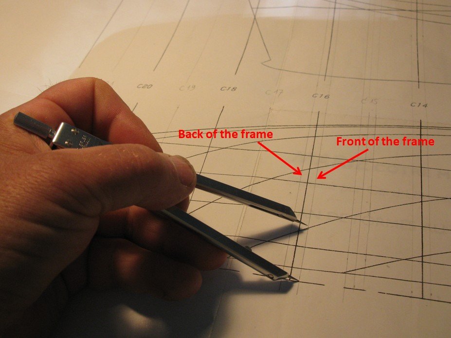
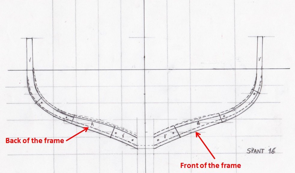
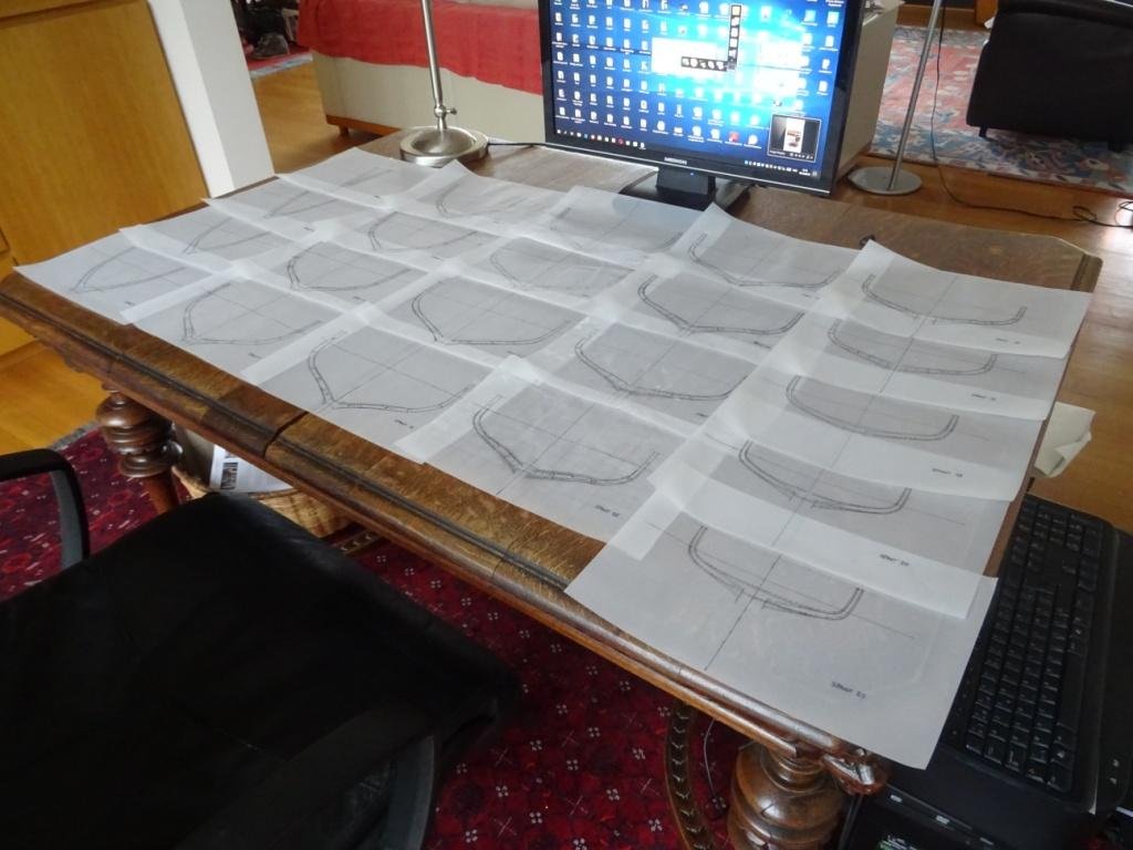
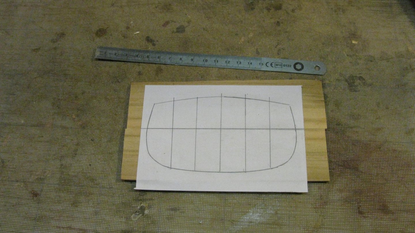
2. The frames The vessel has 22 frames. Frame drawings are not included in the book 'Apprendre le modelisme naval' so I will have to make myself. No worry, I like the drawing board work. I start by drawing the front and aft side of the frames on the half breadth plan and then measure the measure of each water line on the front of the frame with the divider. I bring over the measurement to the frame plan and mark it. I do the same with every buttock line. At the end, I have a series of pencil marks which show the outline of the frame. With the help of the French curve rules the marks are connected and form the shape of the front side of the frame. The whole process is now to be repeated to draw the back side of the frame. The complete frame. The uninterrupted line is the front side of the frame and the dashed line is the back side of the frame. On this drawing the insides of the frame are also drawn as well as the subdivision in futtocks. It takes some time, but after a while all 22 frames are drawn. Now we make a jump ahead of some weeks and here they are spread out on my desktop. Thank you for the likes Thank you to follow Thank you for your constructive comments. Till next week!


- 168 replies
-
- 19
-

-
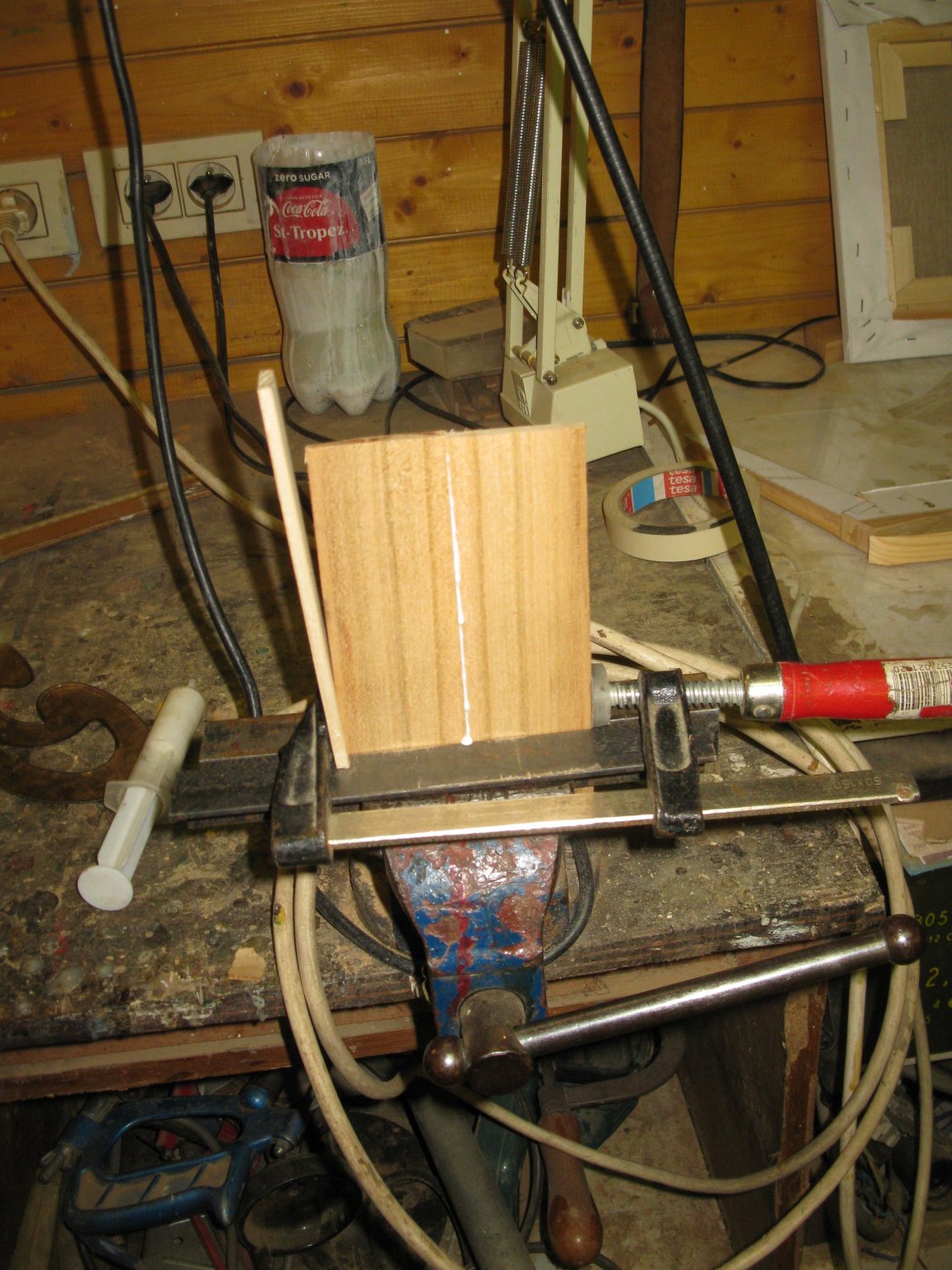
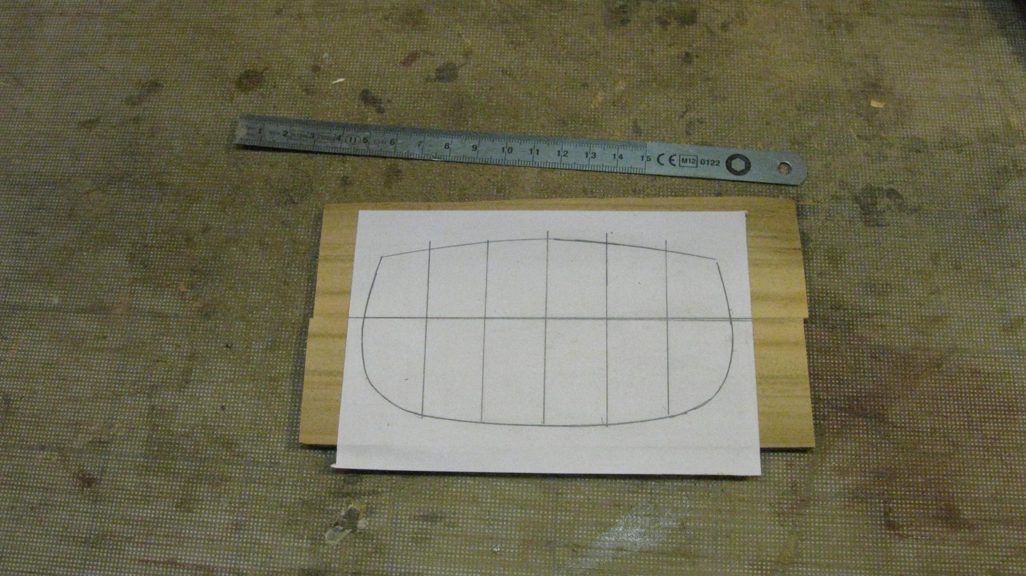
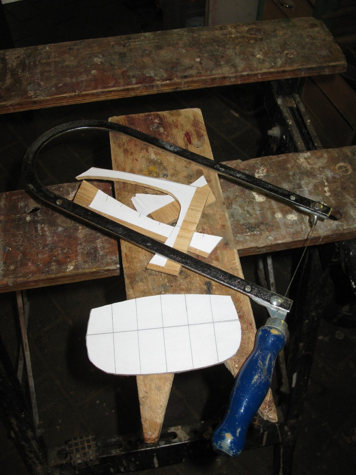
I glue two planks together to make the transom. With the help of a paper template, the transom is sawn out. The glued parts are reinforced with bamboo dowels.


- 168 replies
-
- 12
-
-
Thank you for the advise Michael. I will certainly cast more pieces in the future and take it into account.
-
GIGINO by mhkash - FINISHED - brigantine
G.L. replied to mhkash's topic in - Build logs for subjects built 1901 - Present Day
Congratulations for the completion of your brigantine schooner.- 26 replies
-
- 2
-
-
- gigino
- brigantine
- (and 1 more)
-
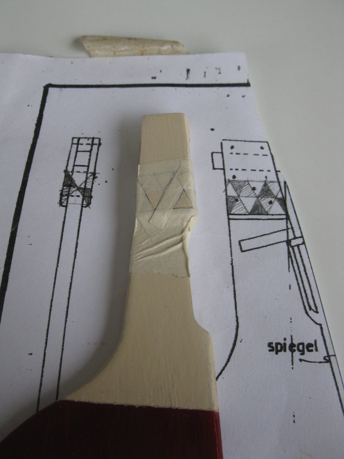
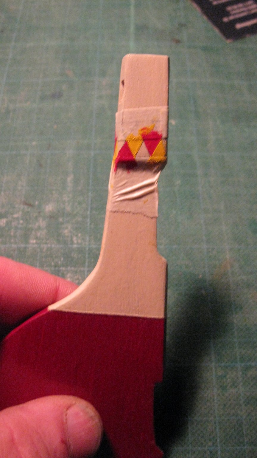
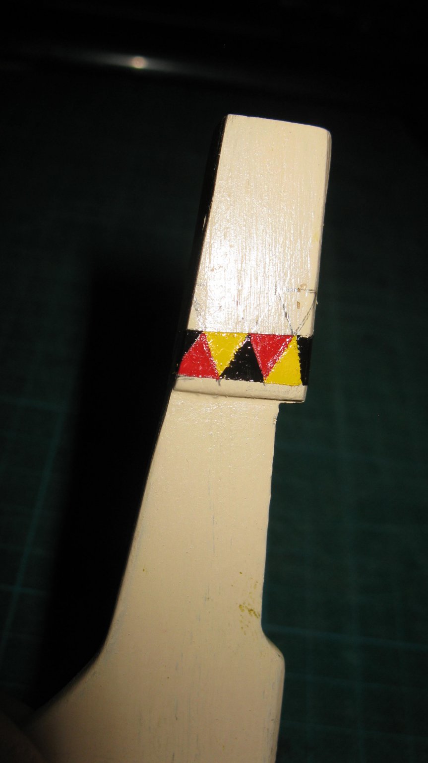
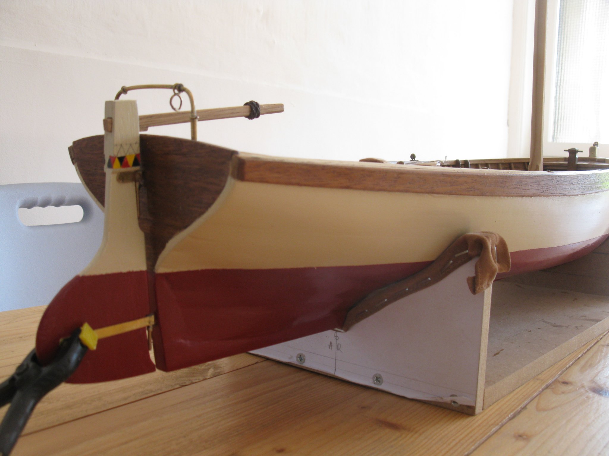
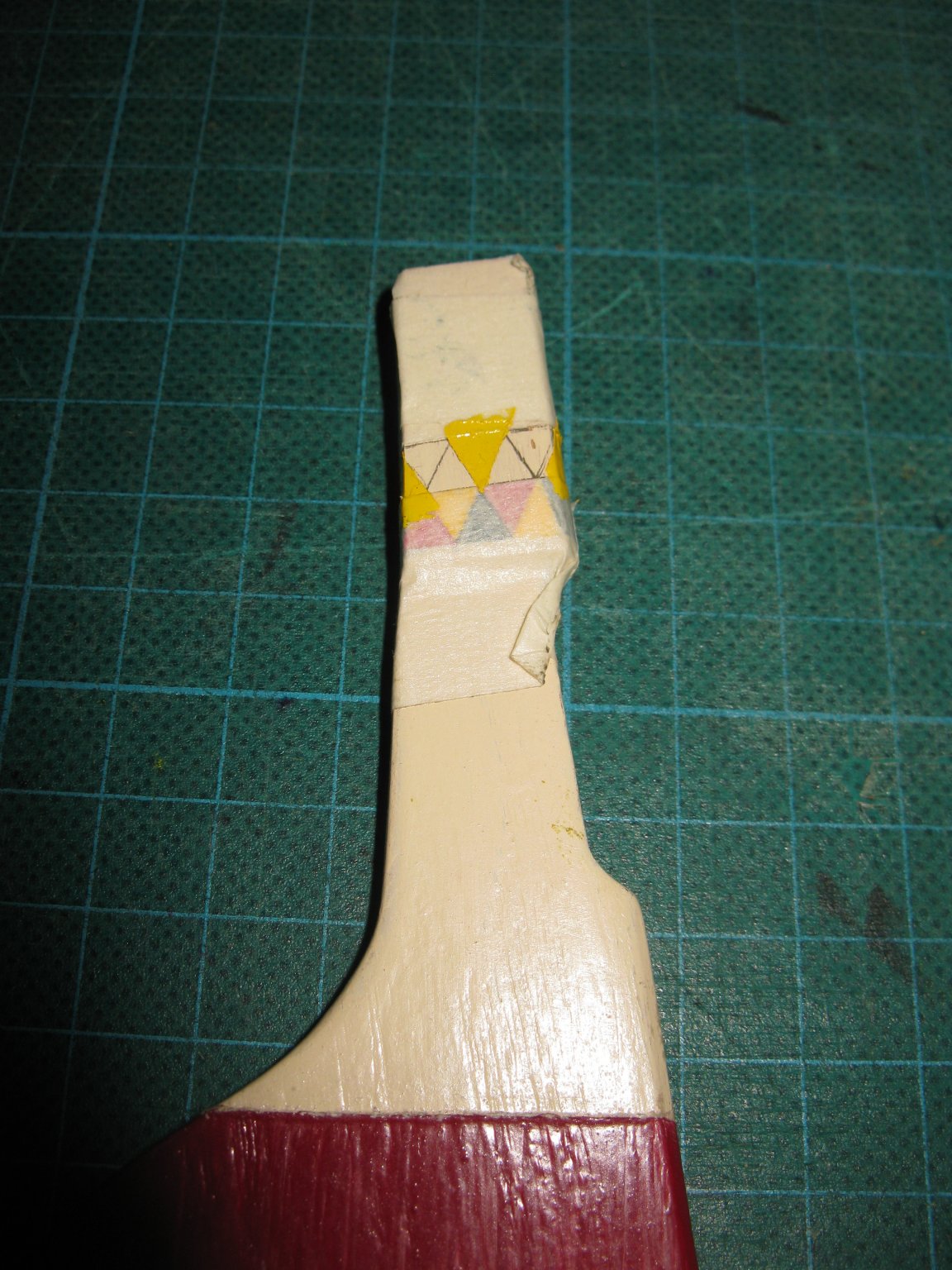
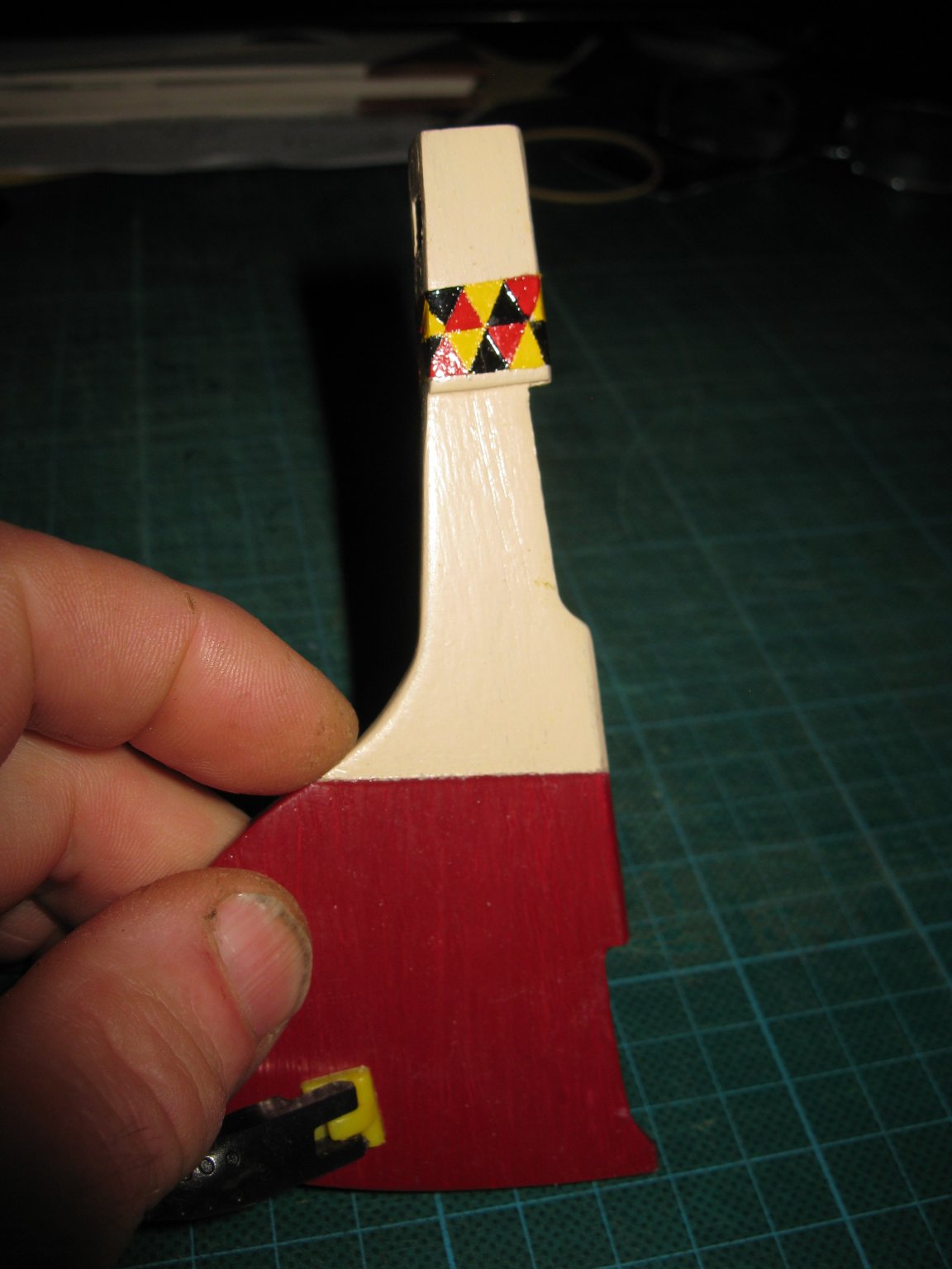
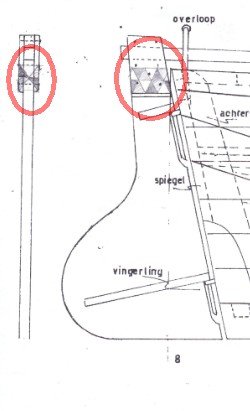
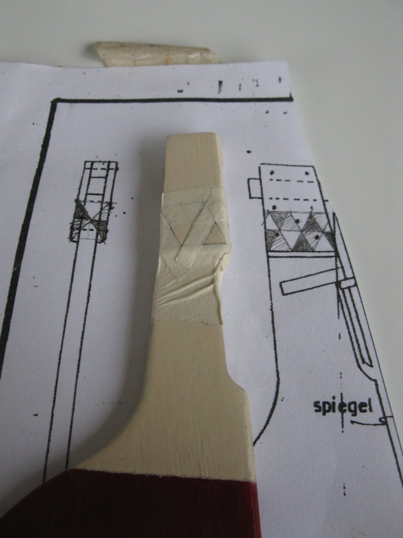
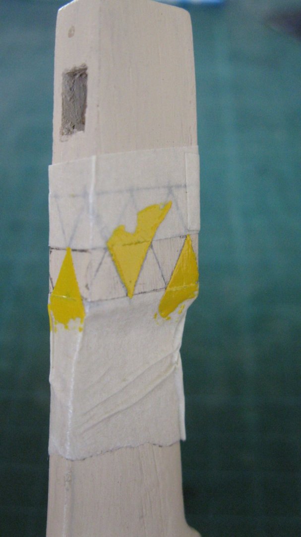
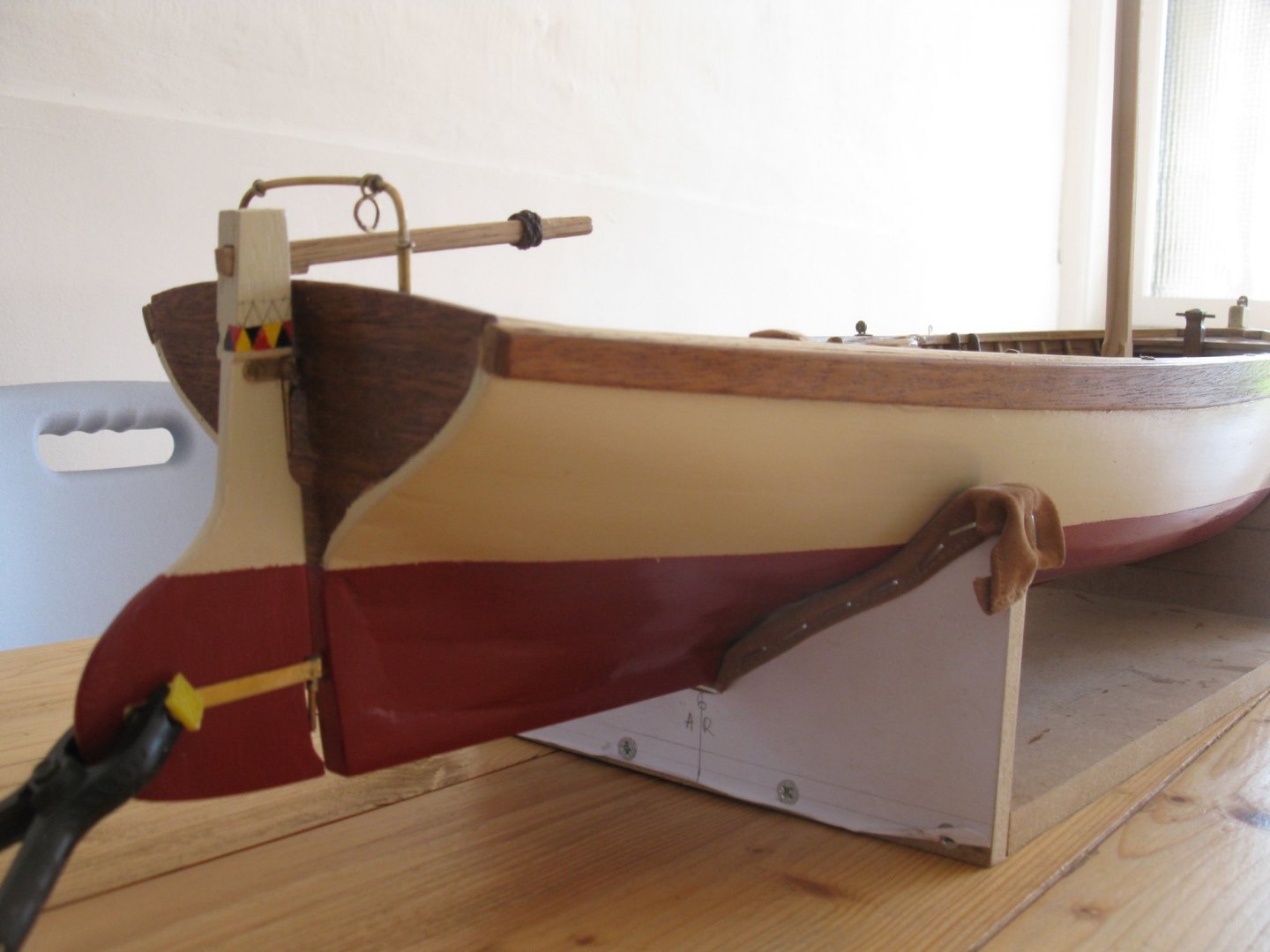
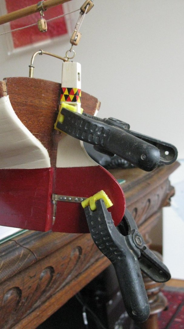
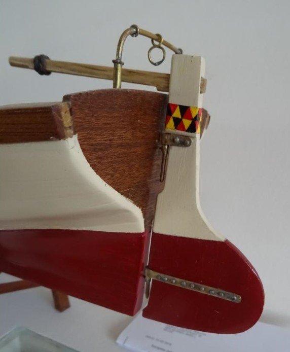
9.2. Finishing the rudder To make the rudder a bit more fancy I will add some 'Prinswerk' on it. 'Prinswerk' (Prince work) is often seen on traditional Dutch vessels which are decorated with a strip of orange, blue and white triangles. With my apologizes for our Dutch friends, I will not use the Dutch orange, blue, white but instead the Belgian colors because my boat is sailing under Belgian flag. Starting with taping the bottom strip. I start to paint the yellow triangles... ... then the red ... The bottom strip is painted. It is quickly explained here in a few words, but in reality it is very much time consuming because each color must be fully dried before it can be re-taped for the next color. Taking a look how it is presenting on the transom before starting with the upper strip. The process is repeating: taping, painting, waiting until it's dry, removing the tape, re-taping, painting next color, ... And finally the 'Prince work' is ready. Fixing the rudder to the model. Thank you for the likes Thank you to follow Thank you for the constructive comments, Till next week


- 209 replies
-
- 12
-
-
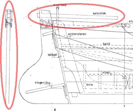
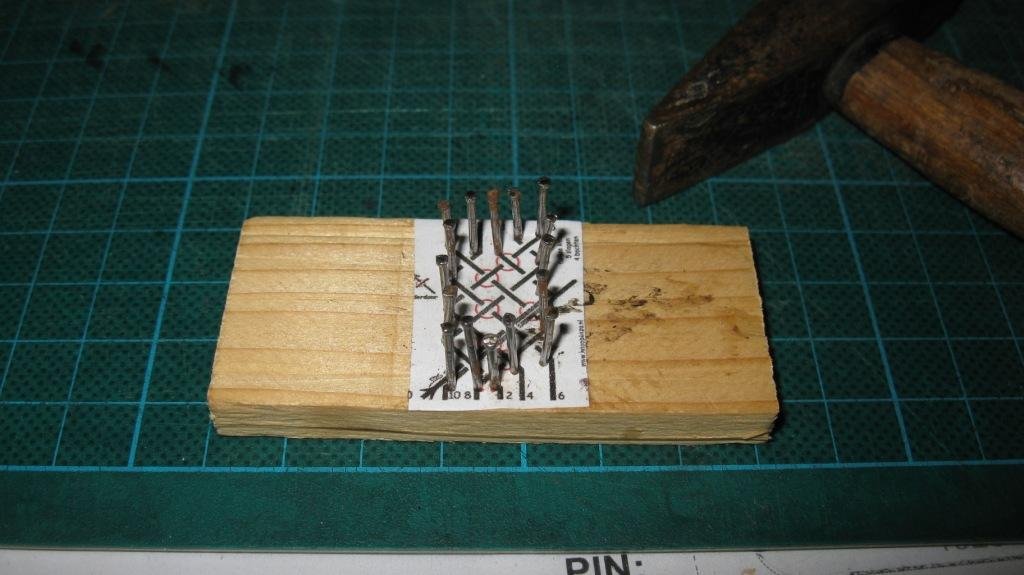
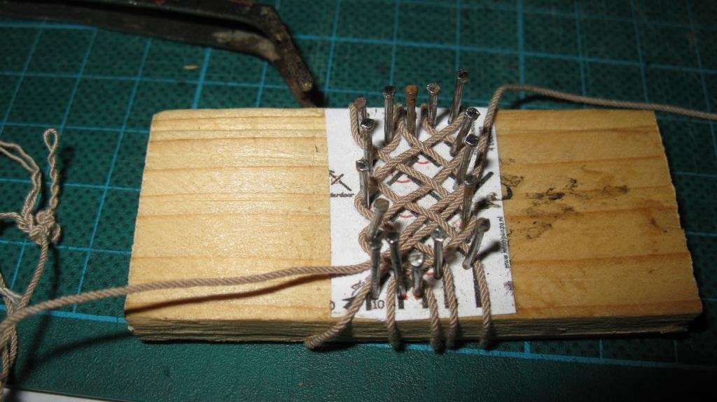
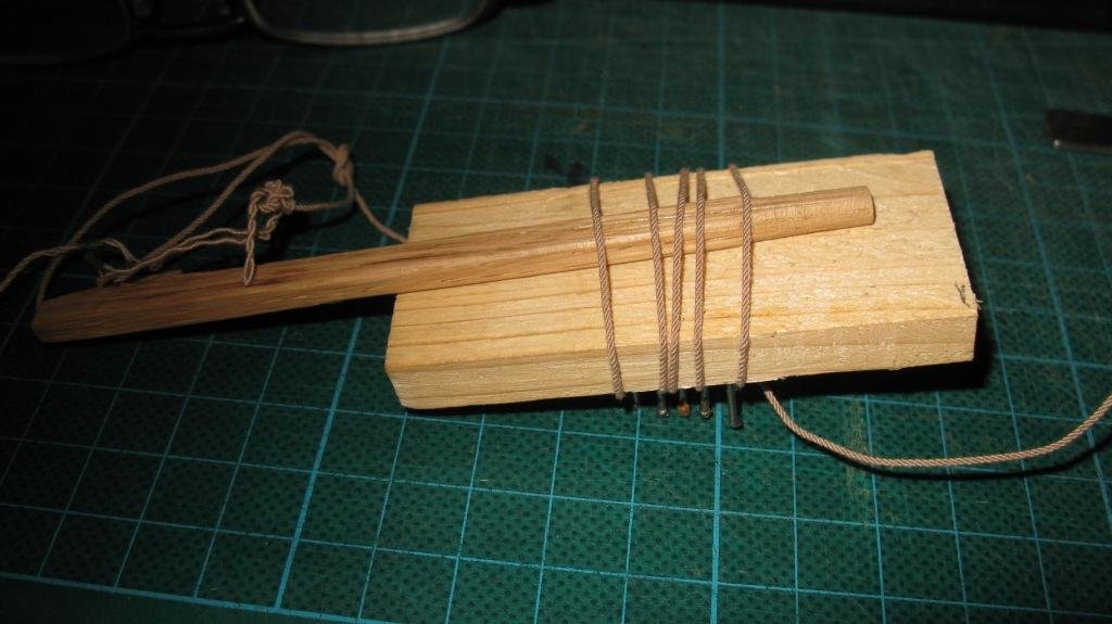
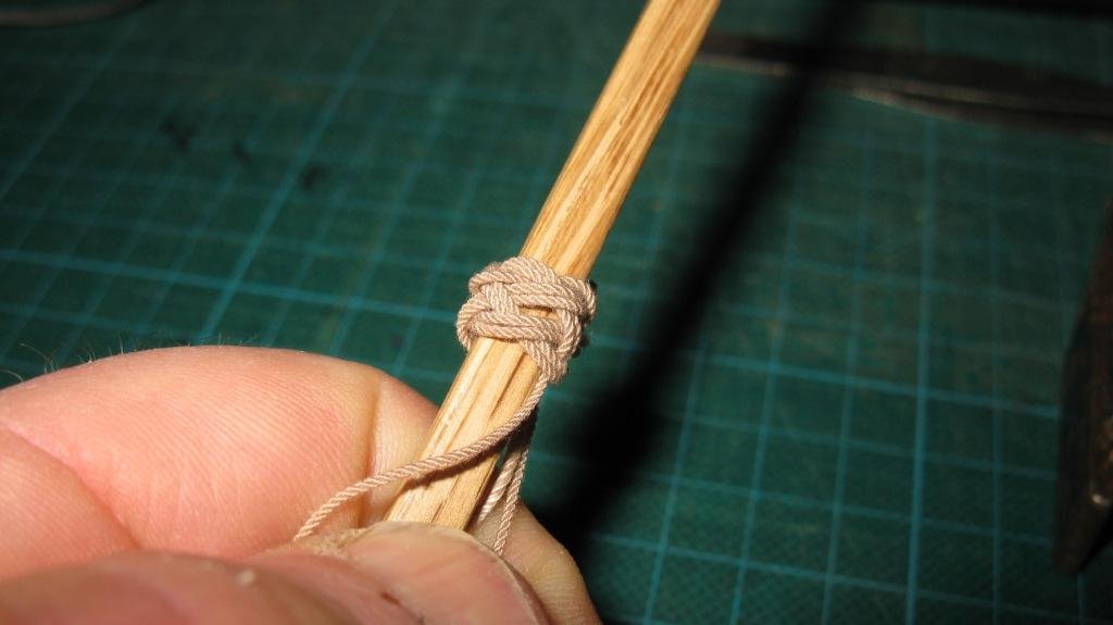
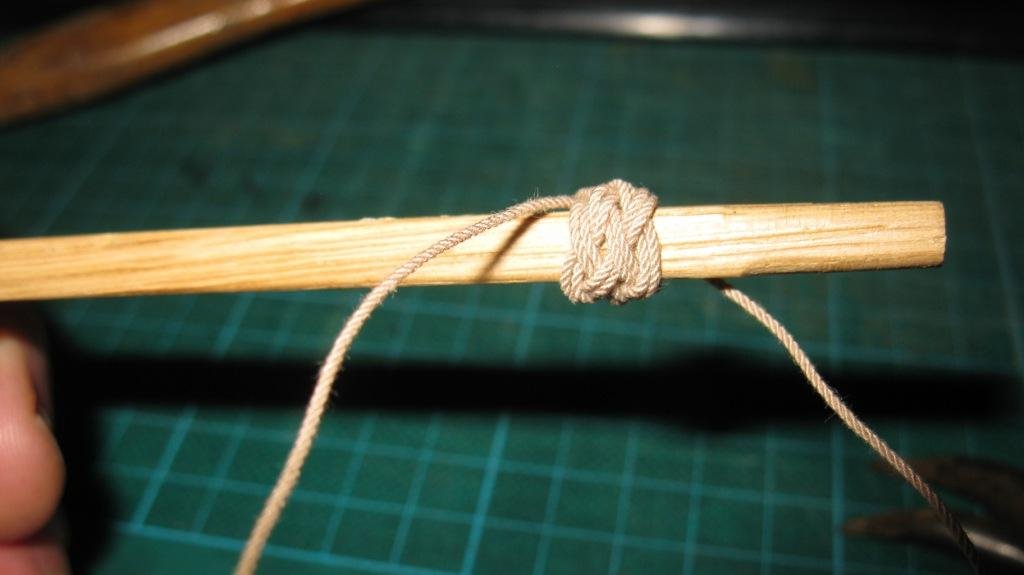
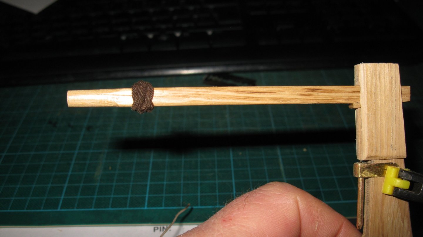
Continuation part 9. The rudder 9.1 Finishing the tiller I find the tiller like it is drawn by Mr Van Beylen a bit humdrum straight. I want to give it some fantasy without changing the original design. I decide to decorate it with a Turkish knot. As former navy man I should be able to make one just like that. To my shame I must acknowledge that I had to go Google for a jig. It will be a knot with two strings. Like that it is easy, isn't it? Now I only have to slide the tiller between the jig and the strings, ... ... remove the jig ad to pull the strings. After the ends have been cut and the rope is stained dark. The knot is fixed on the tiller with a drip of second glue.
- 209 replies
-
- 11
-
-
Hello Pete, I don't know if I would dare to let her sail in a pond. But first I wil have to overcome a new challenge: making sails. I have never worked with a sewing machine.
-
Steve, Patrick, Keith, John and Vaddoc, Thank you all for the encouragements. It really motivates to continue and to try to improve.
-
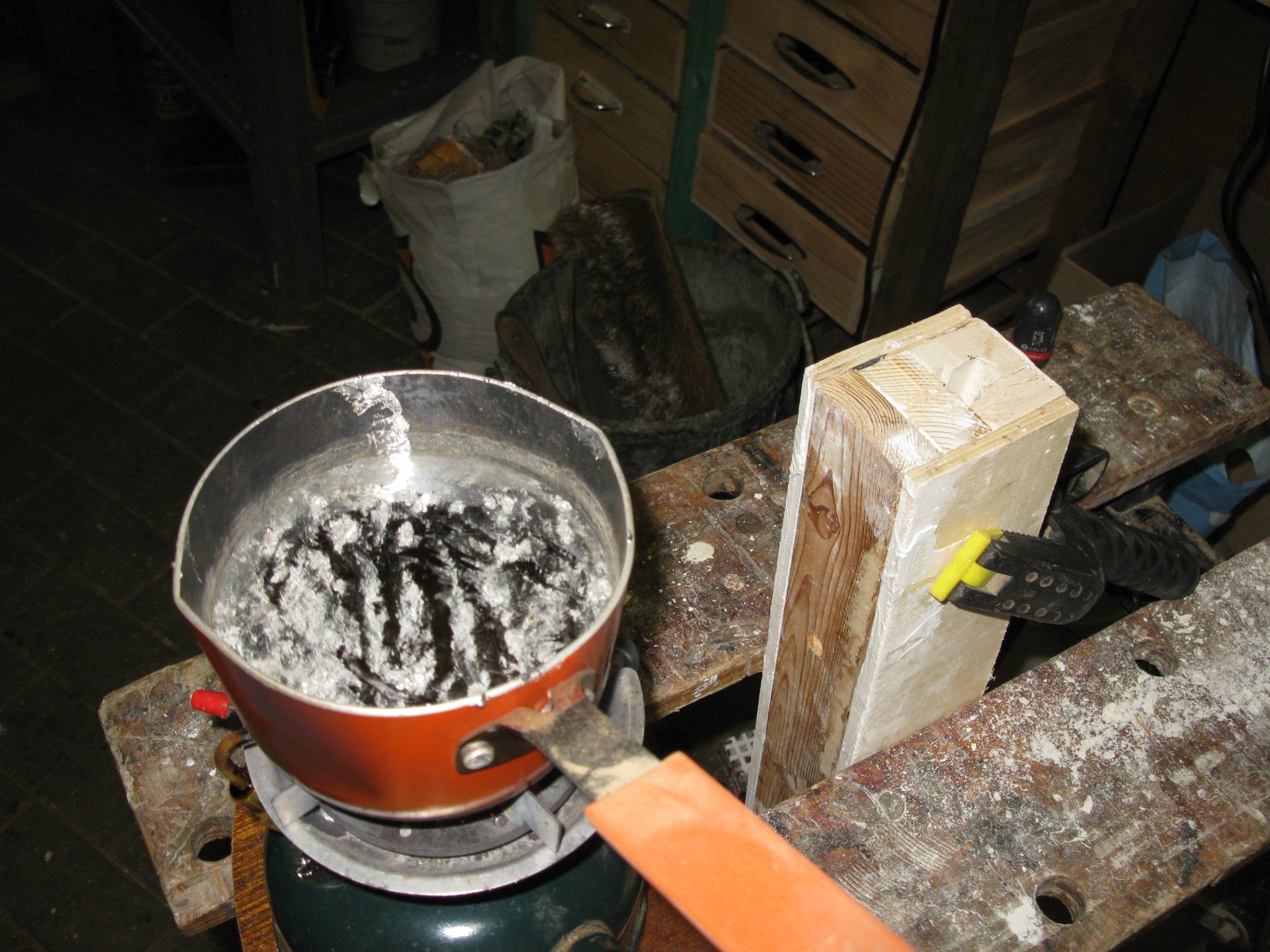
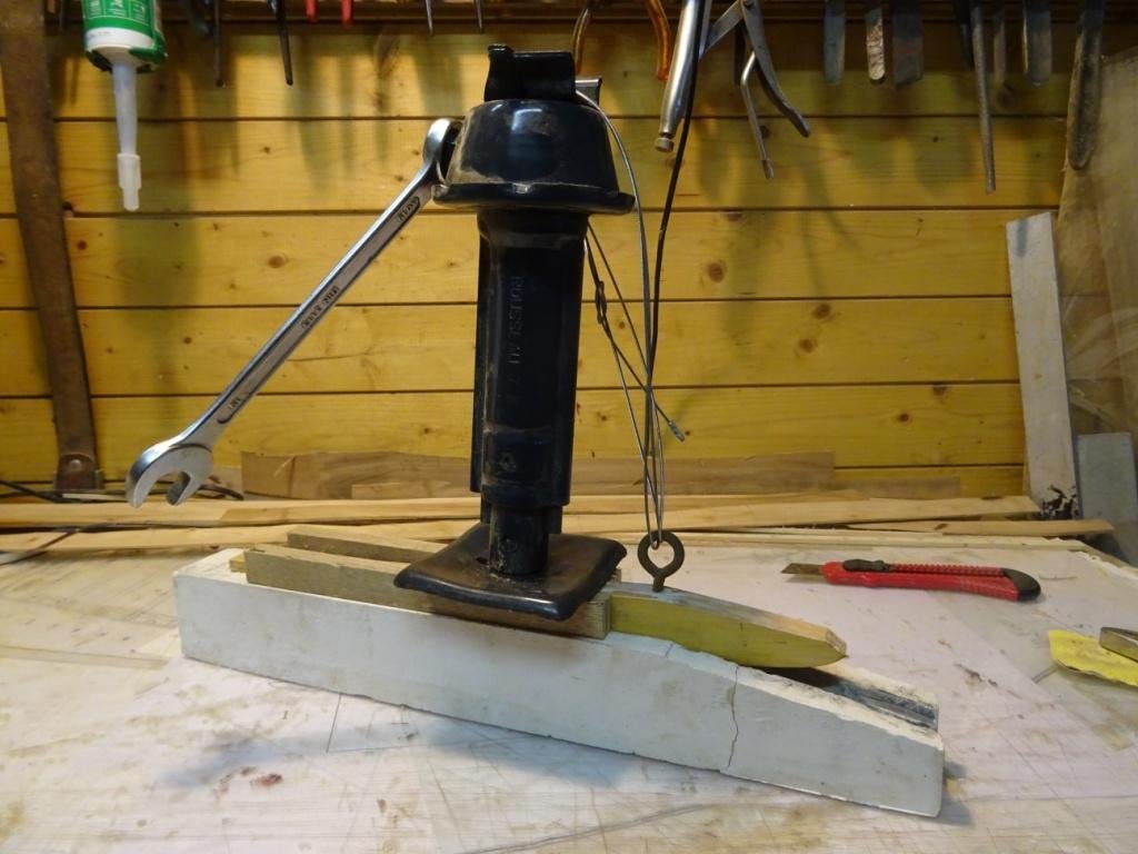
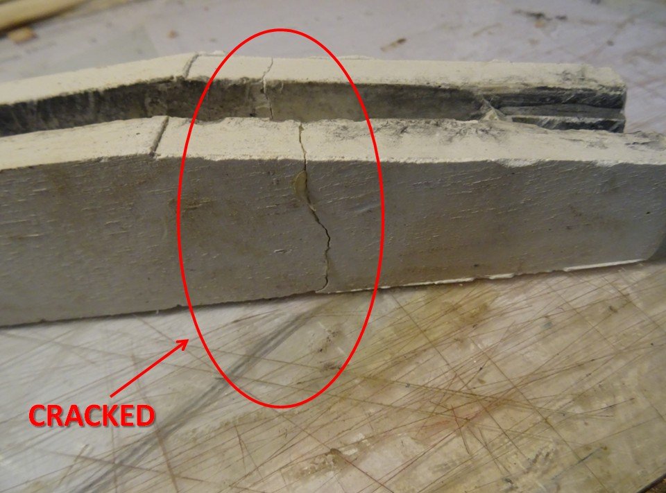
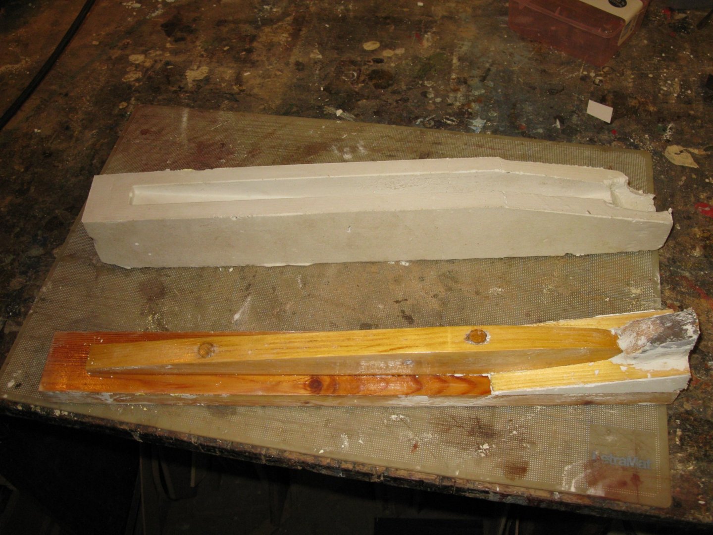
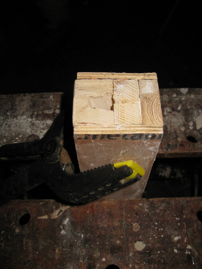
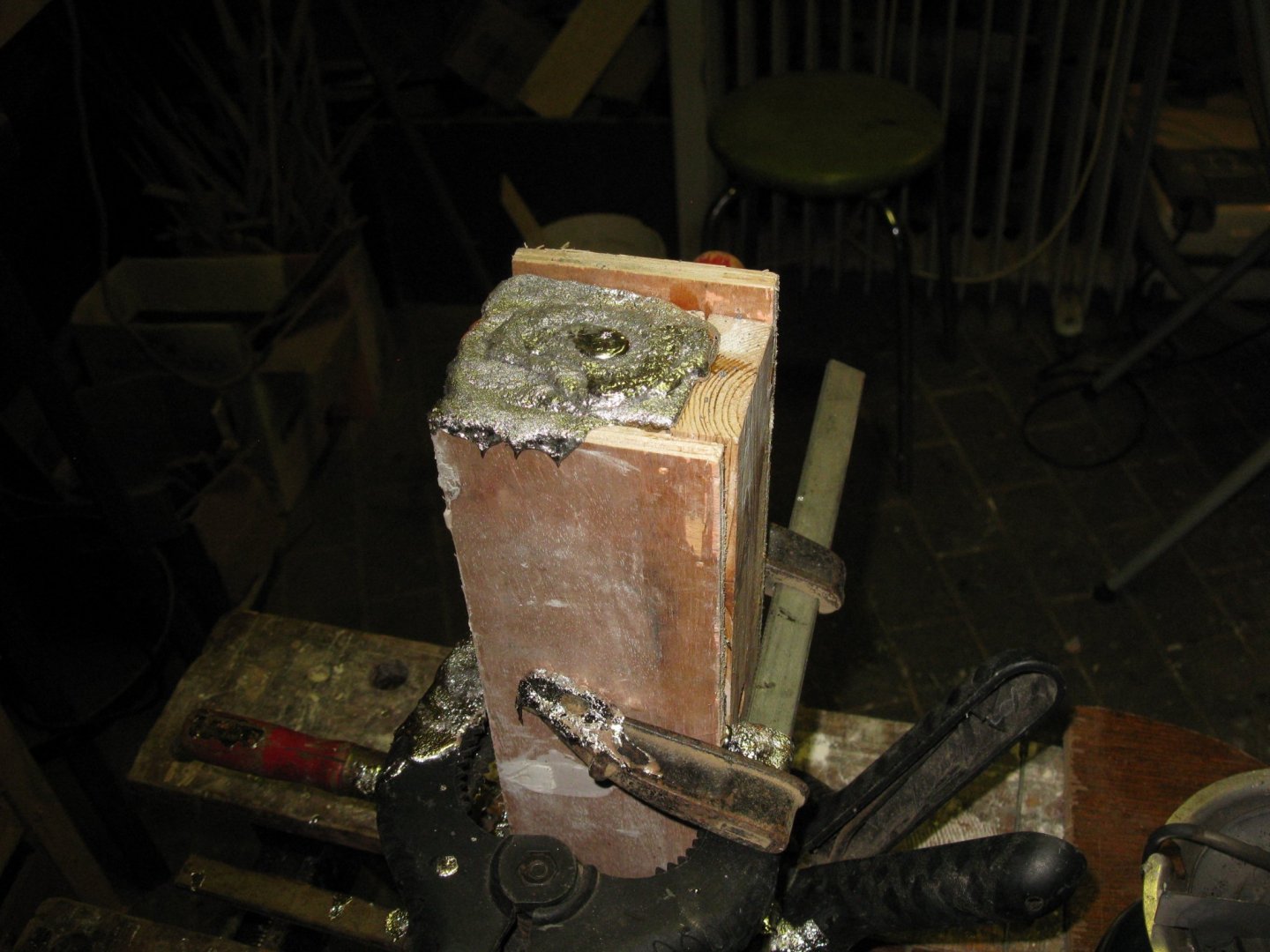
Gary and Keith, I have no idea what it's the composition of the tin bars, I just bought them by the ironmonger and dit not ask about. The wooden plug and the baseplate to make the mold are shiny because I varnished them with high gloss varnish (forgot to report that in my post) to make them less water absorbing so they would loose easier from the plaster. When the plaster was dry the plug was strongly clamped in the plaster (due to its shape), impossible to pull it manually from the mold. I used a car jack. (tried to reconstruct the method to make the picture below.) The casted piece had to be pulled out using the same method, but that had the appendix of the pour funnel that worked as a liver on the plaster mold which made it crack. Fortunately the quality of the casted piece was acceptable and the mold didn't had to be used any more. Between the making of the plaster mold and the pouring of the tin, I waited one week. Probably it would have been better to wait at least twice that time because during pouring, the melted tin was quite fizzy. I believe that that was caused by the humidity which was still in the plaster although it seemed dry.
-
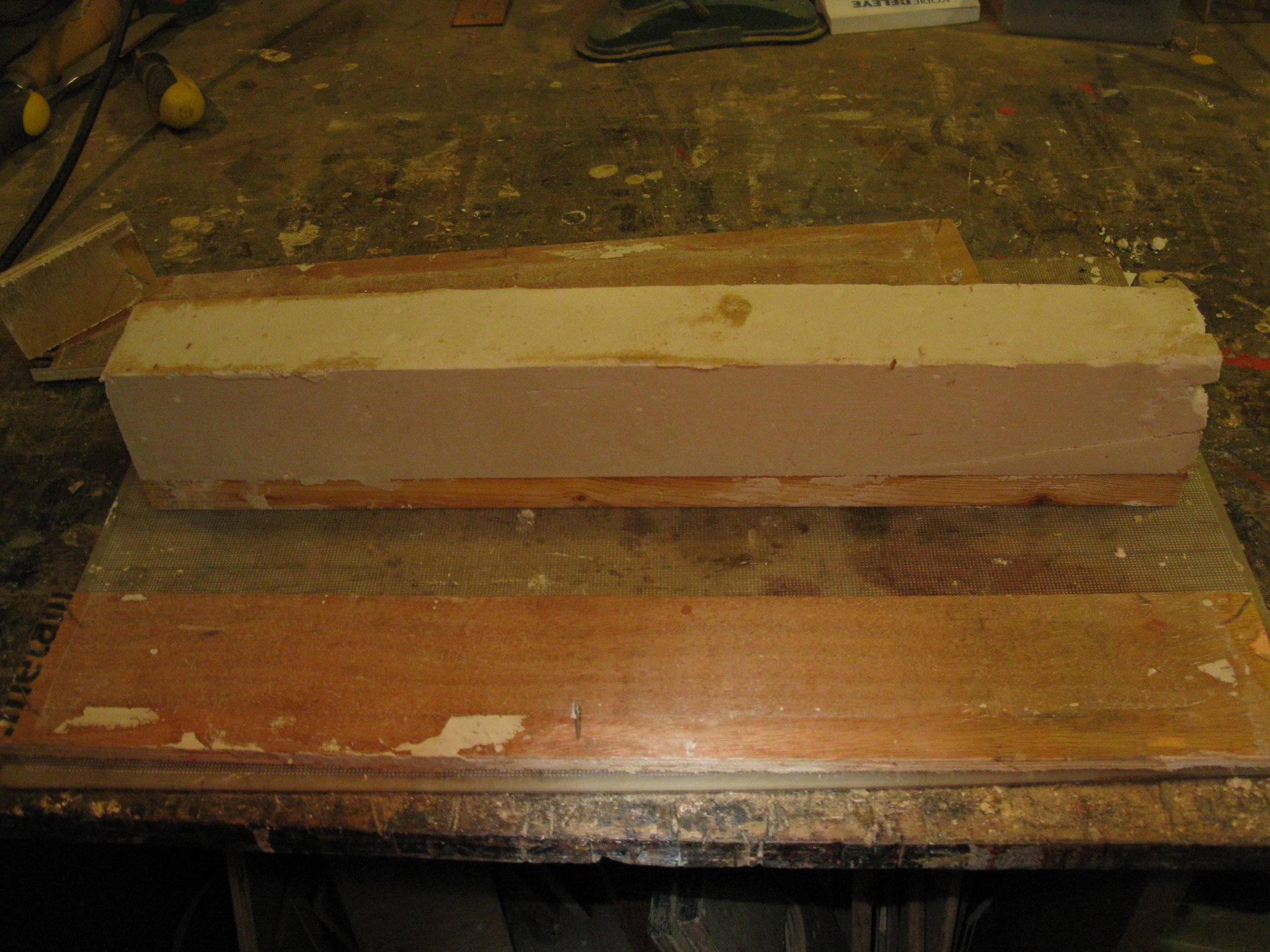
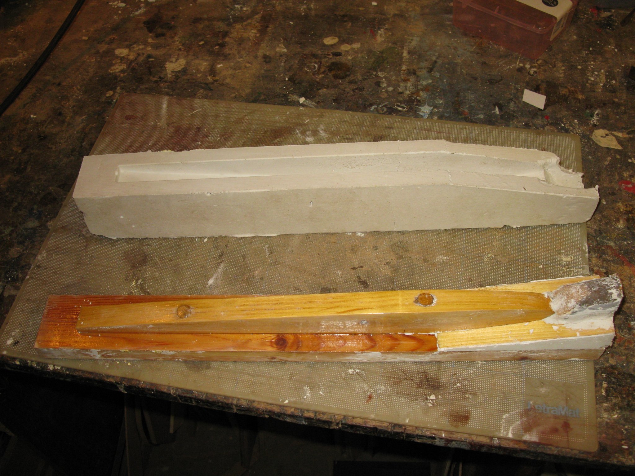
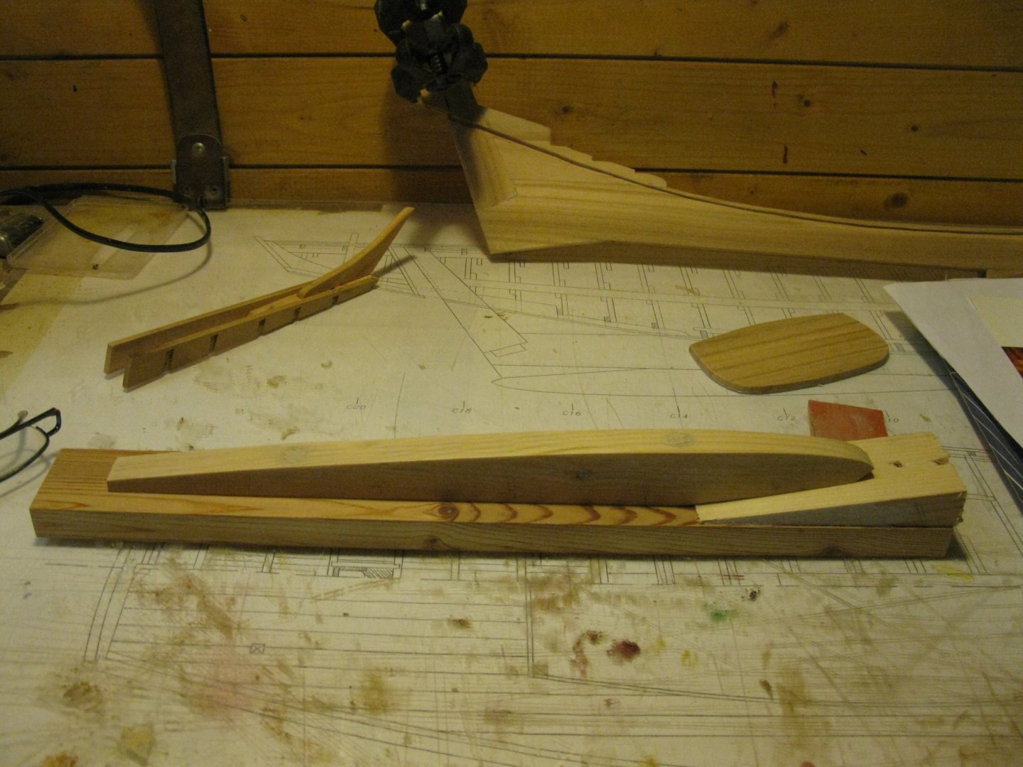
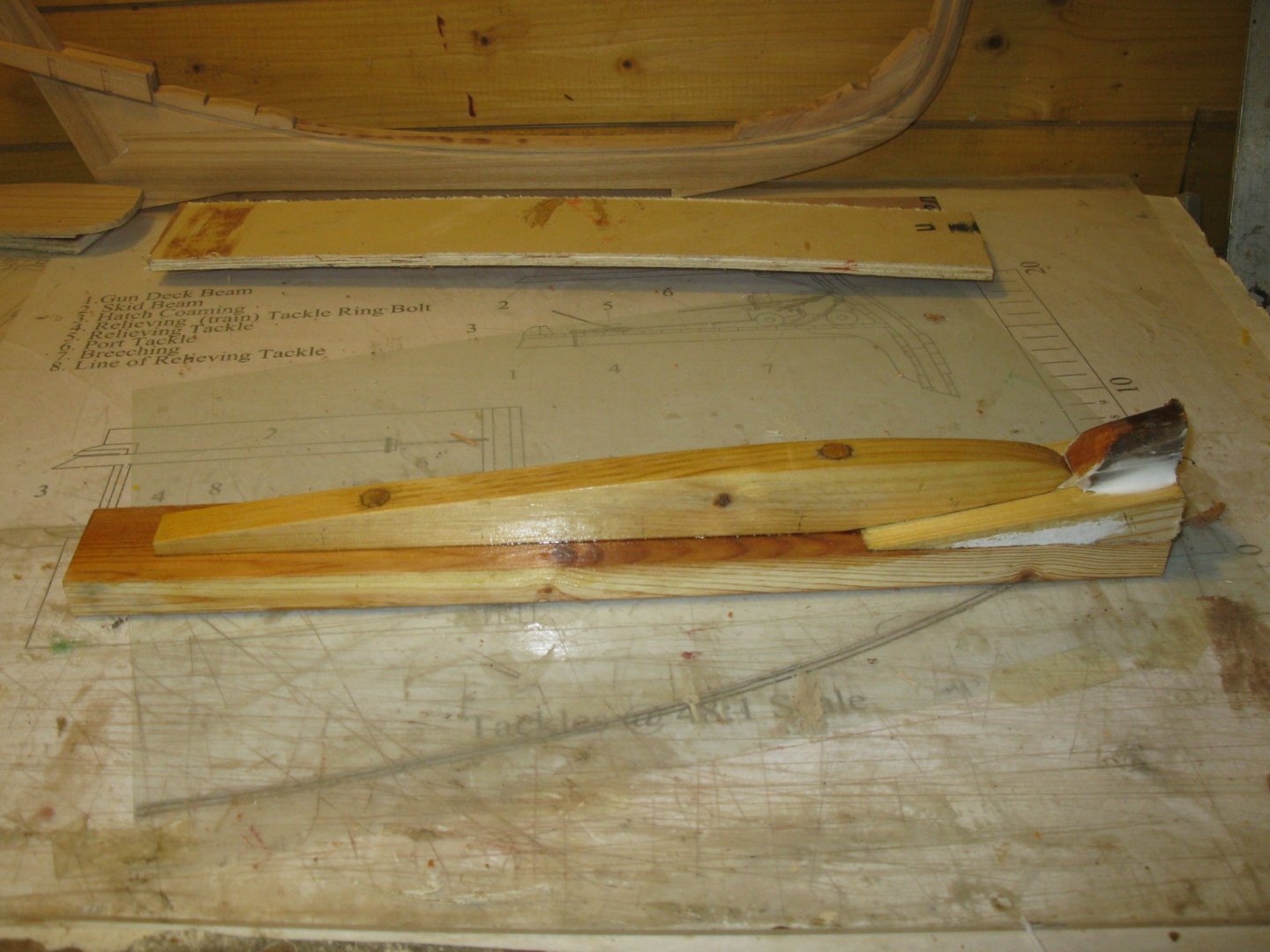
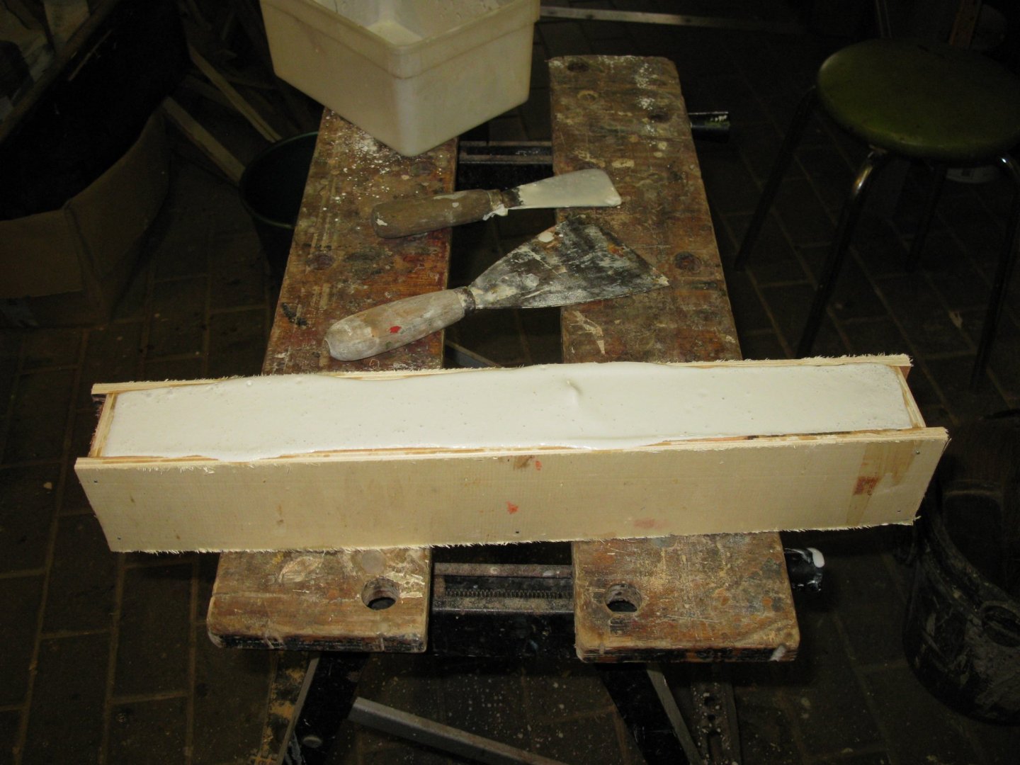
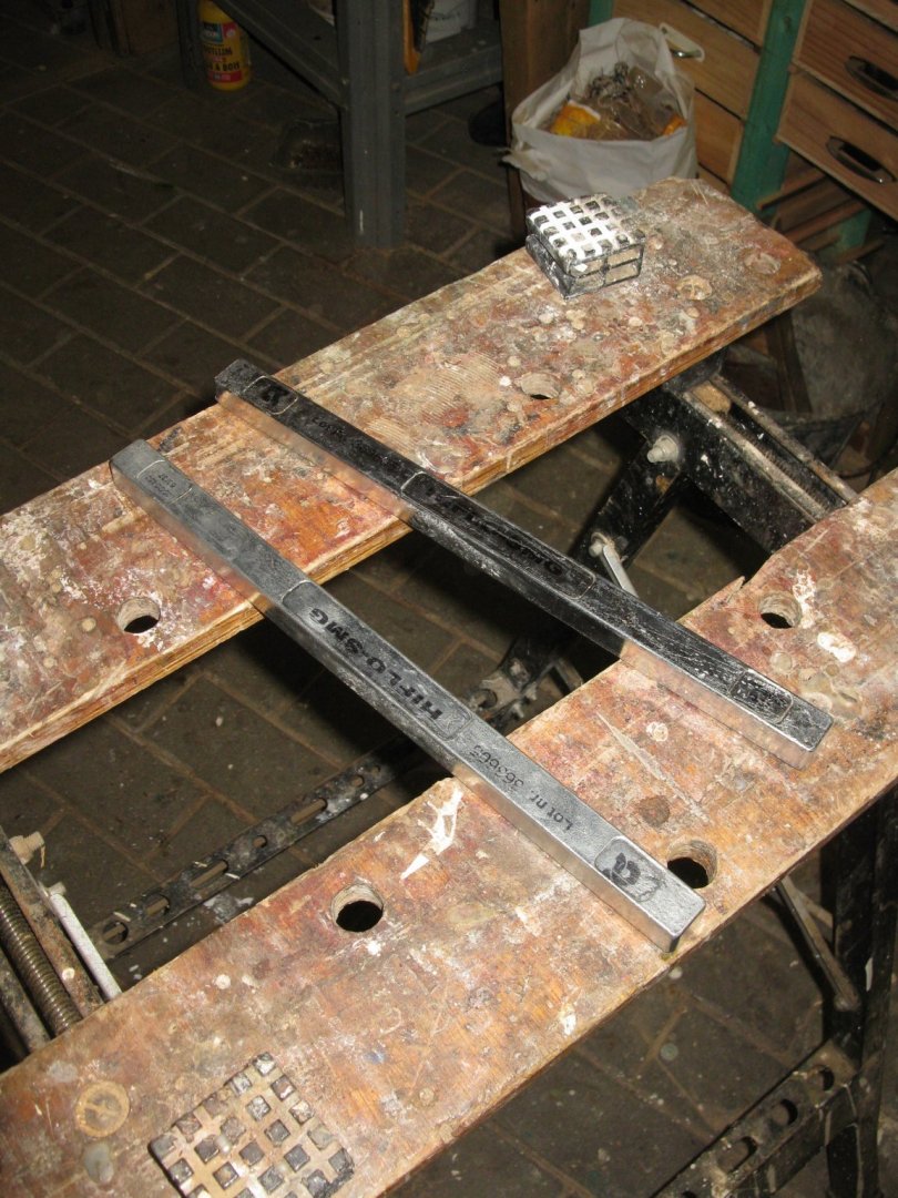
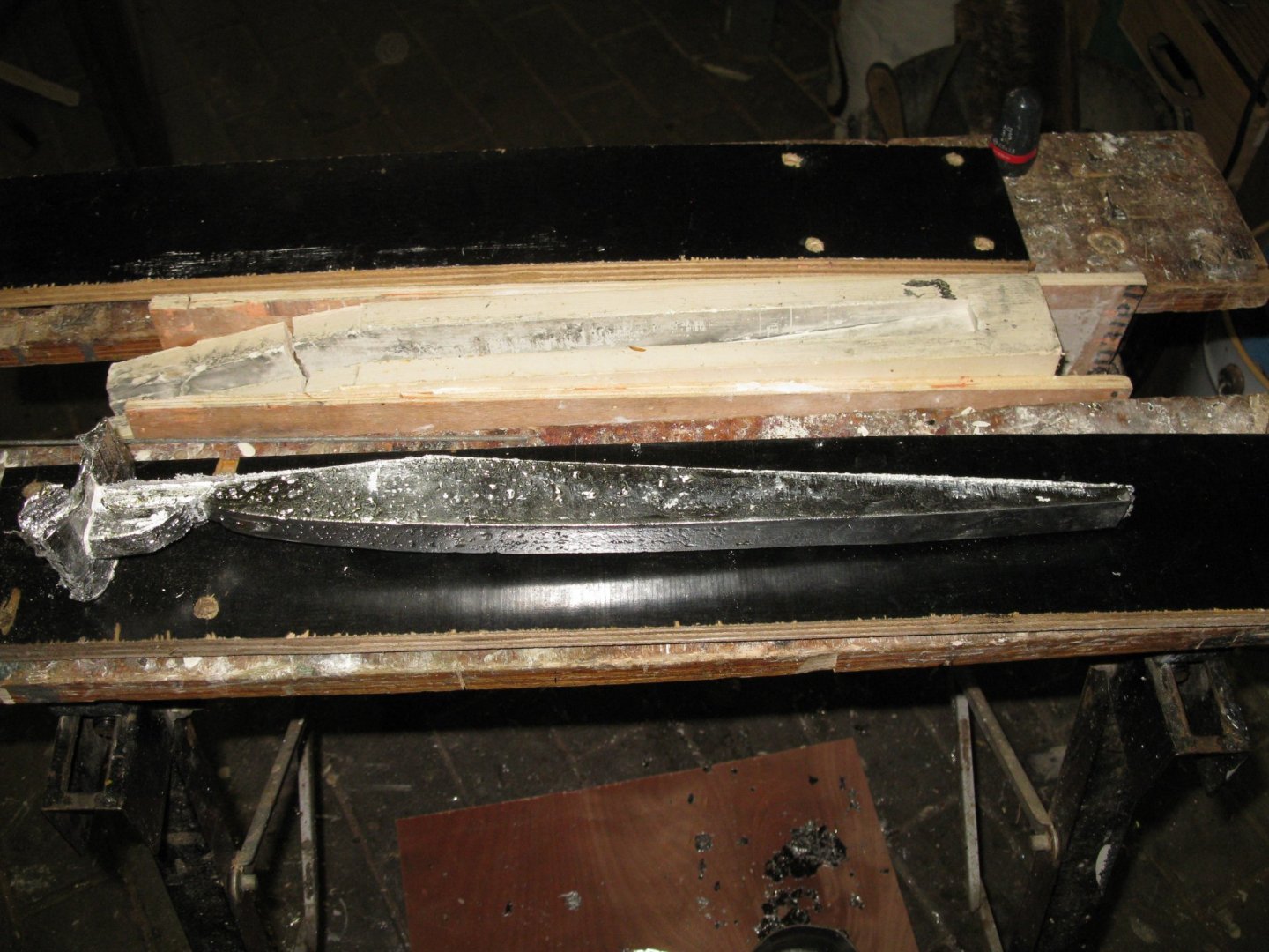
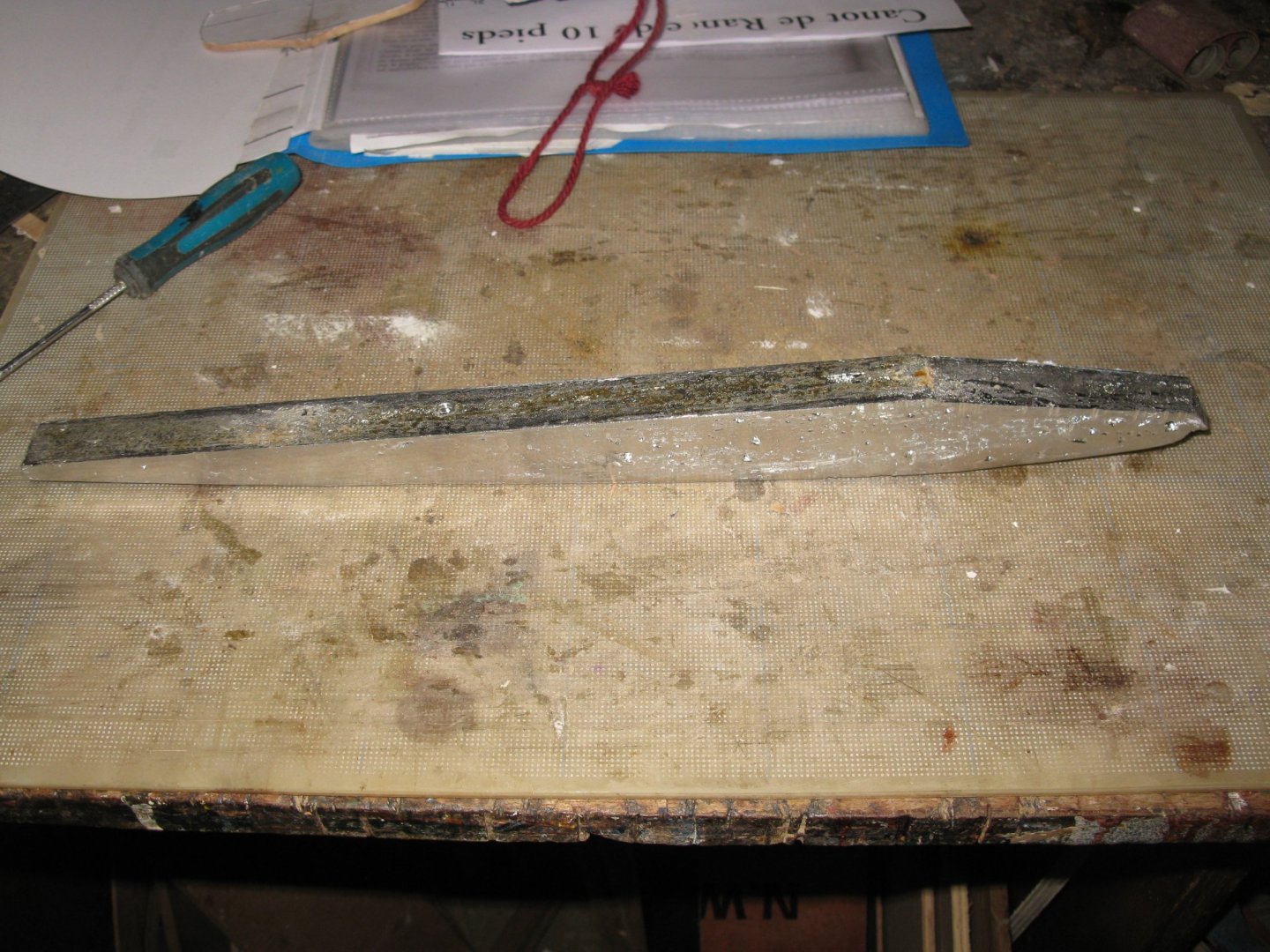
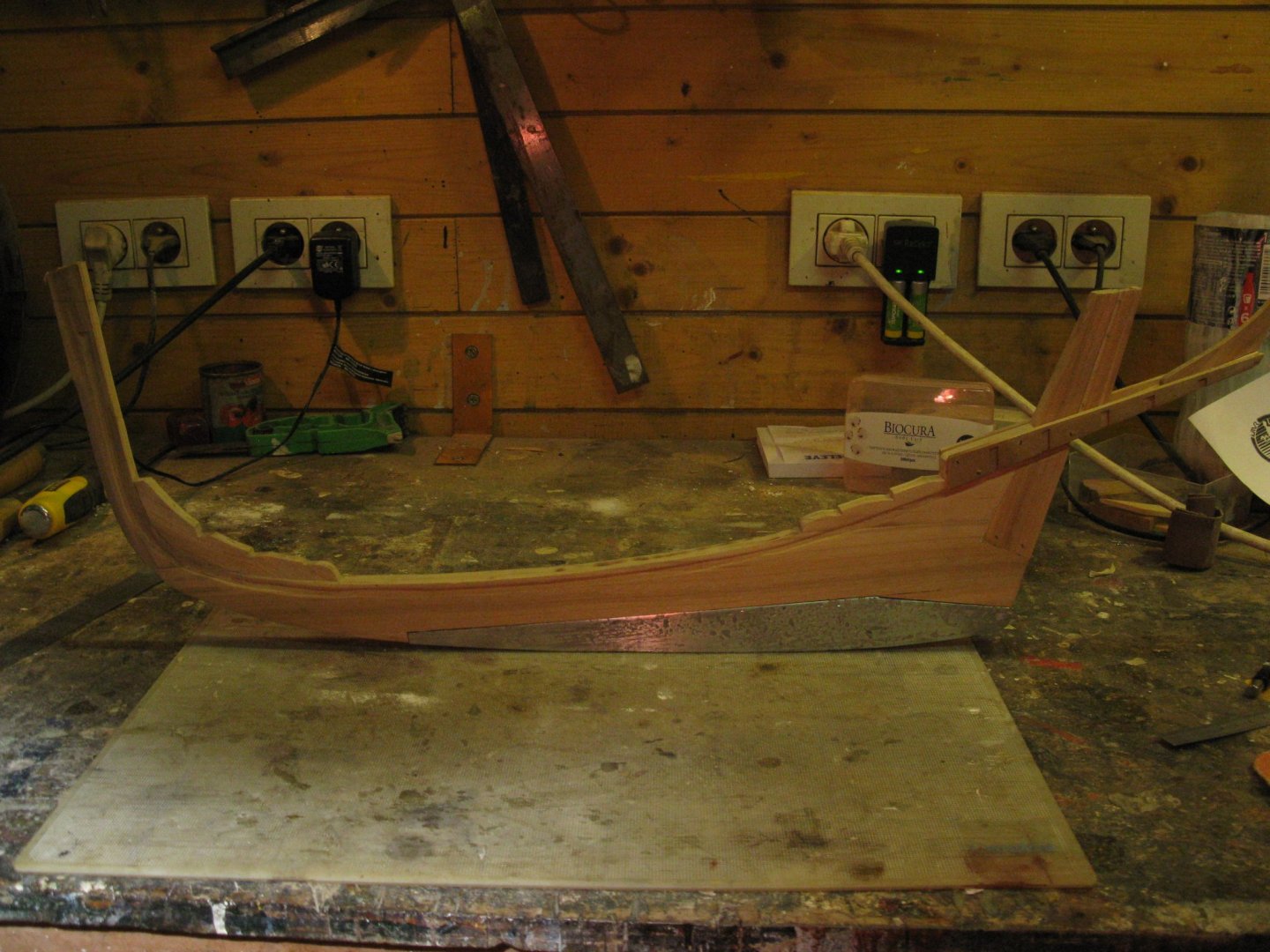
As I mentioned before, I want to make a tin ballast keel to imitate the cast iron keel which had the original vessel. I will make a mold in plaster. I start with making a formwork around my dummy keel. The attached bulb on the second picture serves to make a pour funnel. The mold, filled with plaster. When the plaster dried, I can take it out of the mold (finally I did have to make a new plaster mold, because the one on this picture didn't dry completely and was too fragile due to a wrong mixing ratio between plaster and water (too much water). The new mold, dry and ready to be filled with tin. I bought two staves of plumbers tin. Melting the tin. I did not make a picture of the pouring itself because holding a pan with melted tin in one hand and pour while using the other hand to make a selfie didn't seem a wise idea to me. When the keel is cooled down, it can be taken out of the mold. The appendix at the left side is the pour funnel which has to be sawn off. The finished ballast keel. Fitting the keel on the model Finally the keel is blackened and holes (air bubbles) at the surface are puttied. Now the keel can be stuck to the model with structural glue. Thank you for the likes Thank you to follow Thank you for the constructive comments. Till next week!


- 168 replies
-
- 19
-
-
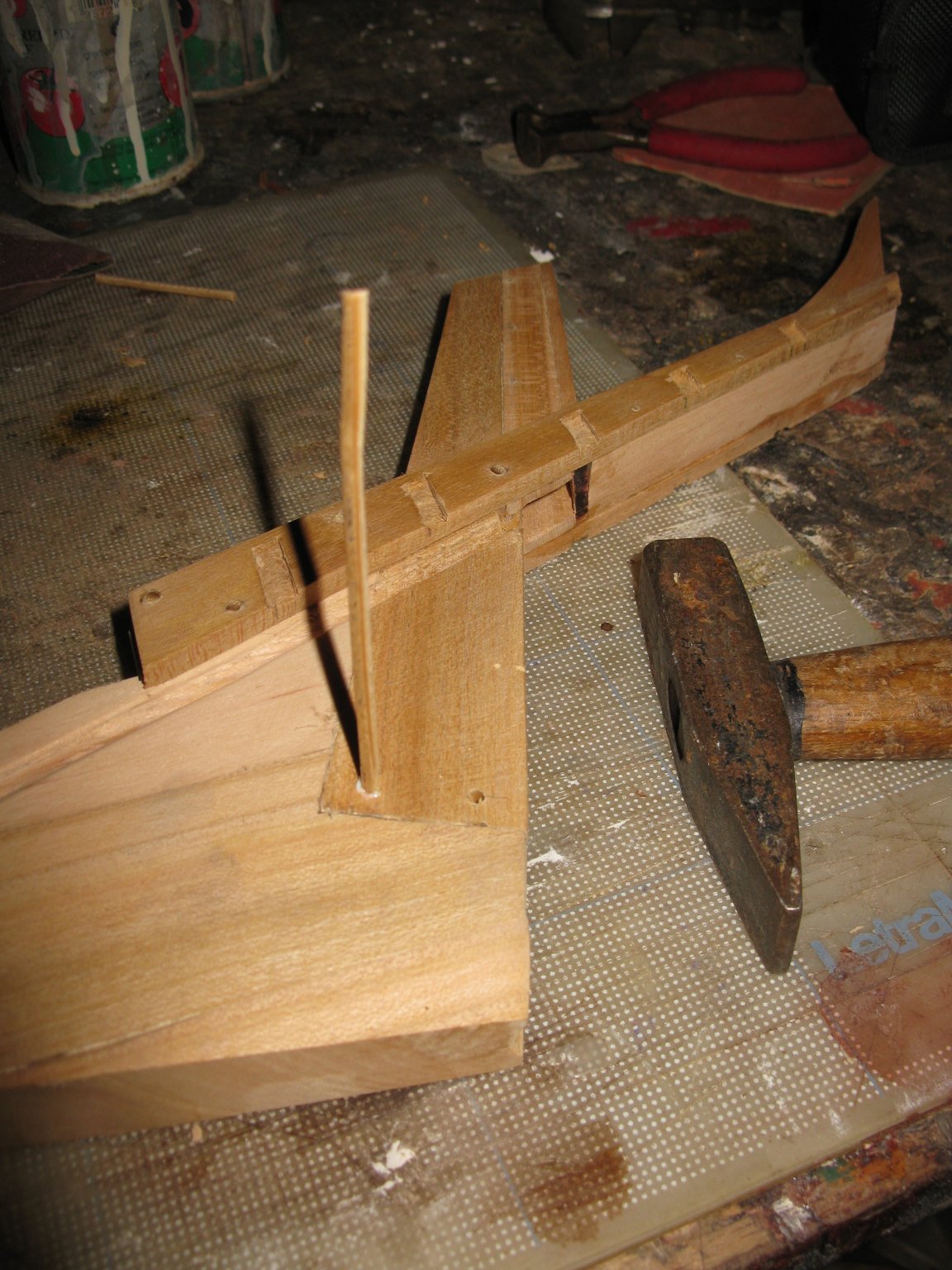
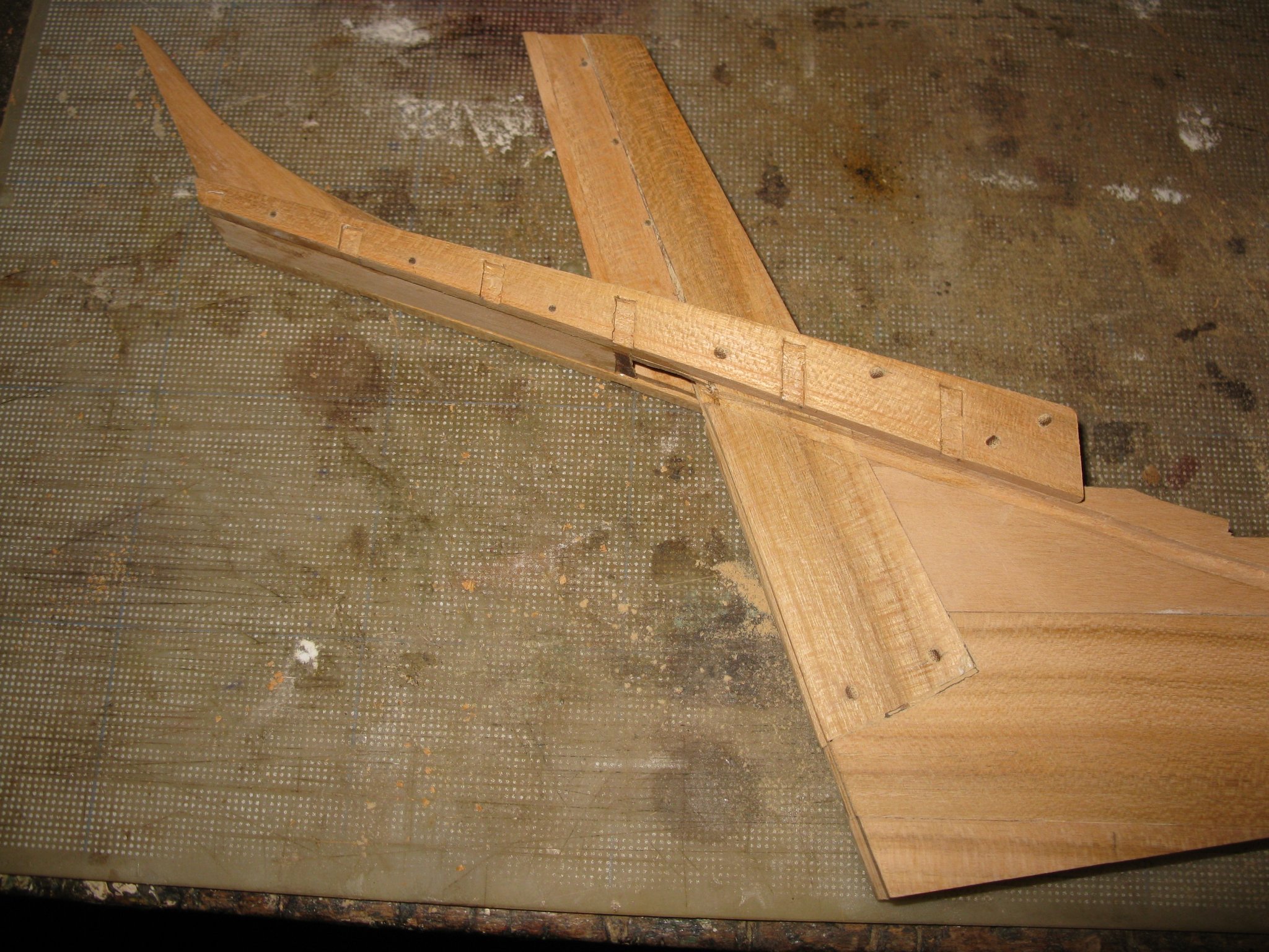
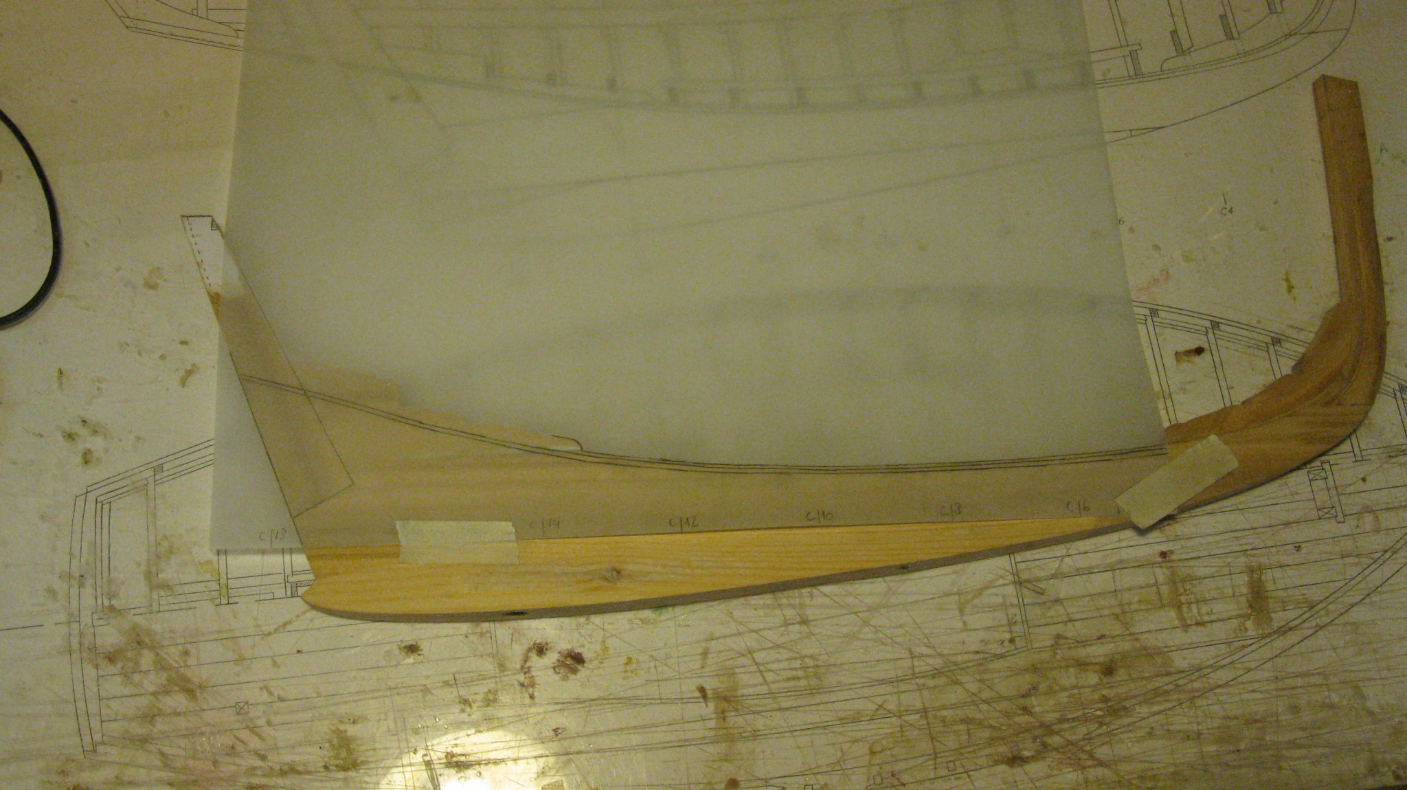
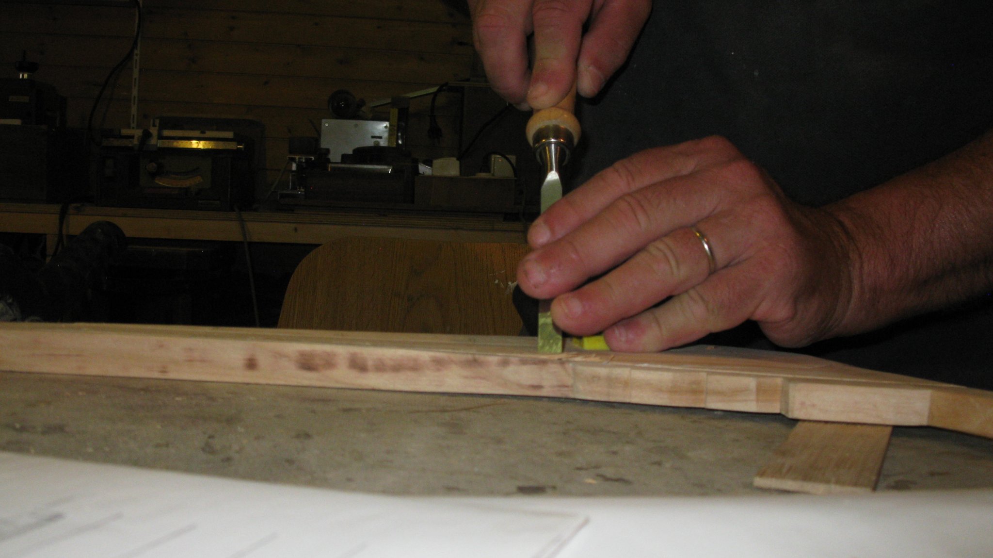
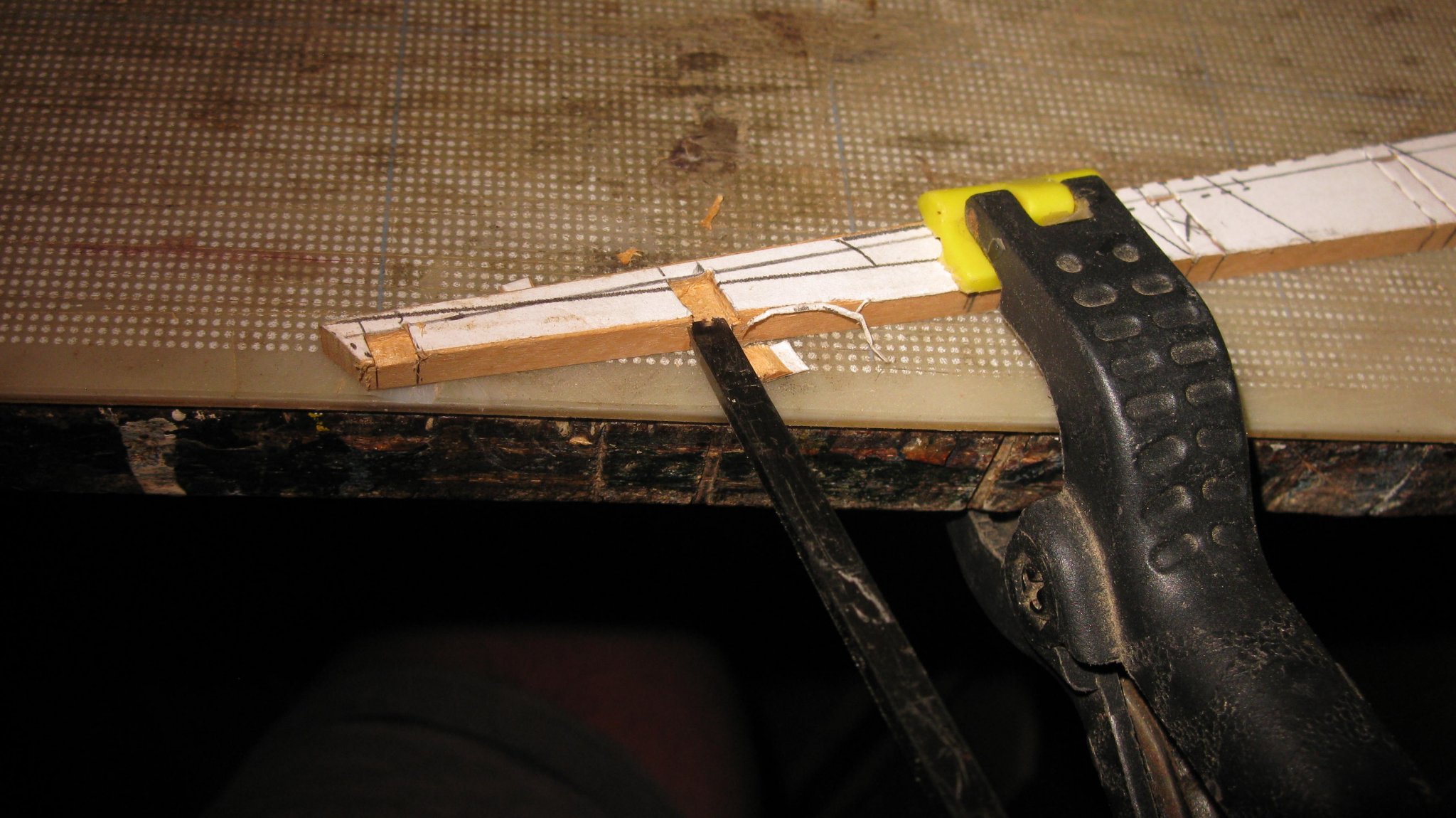
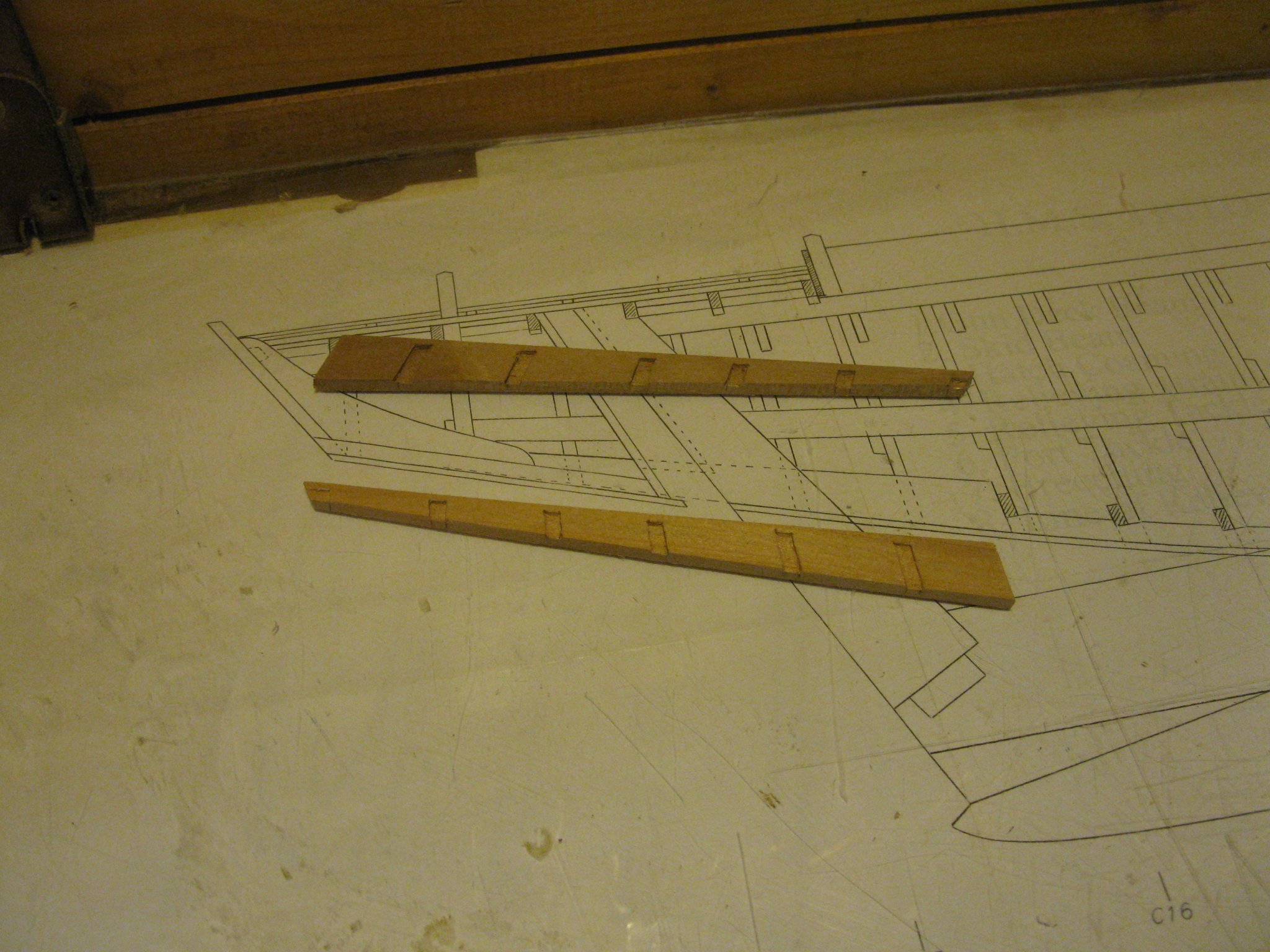
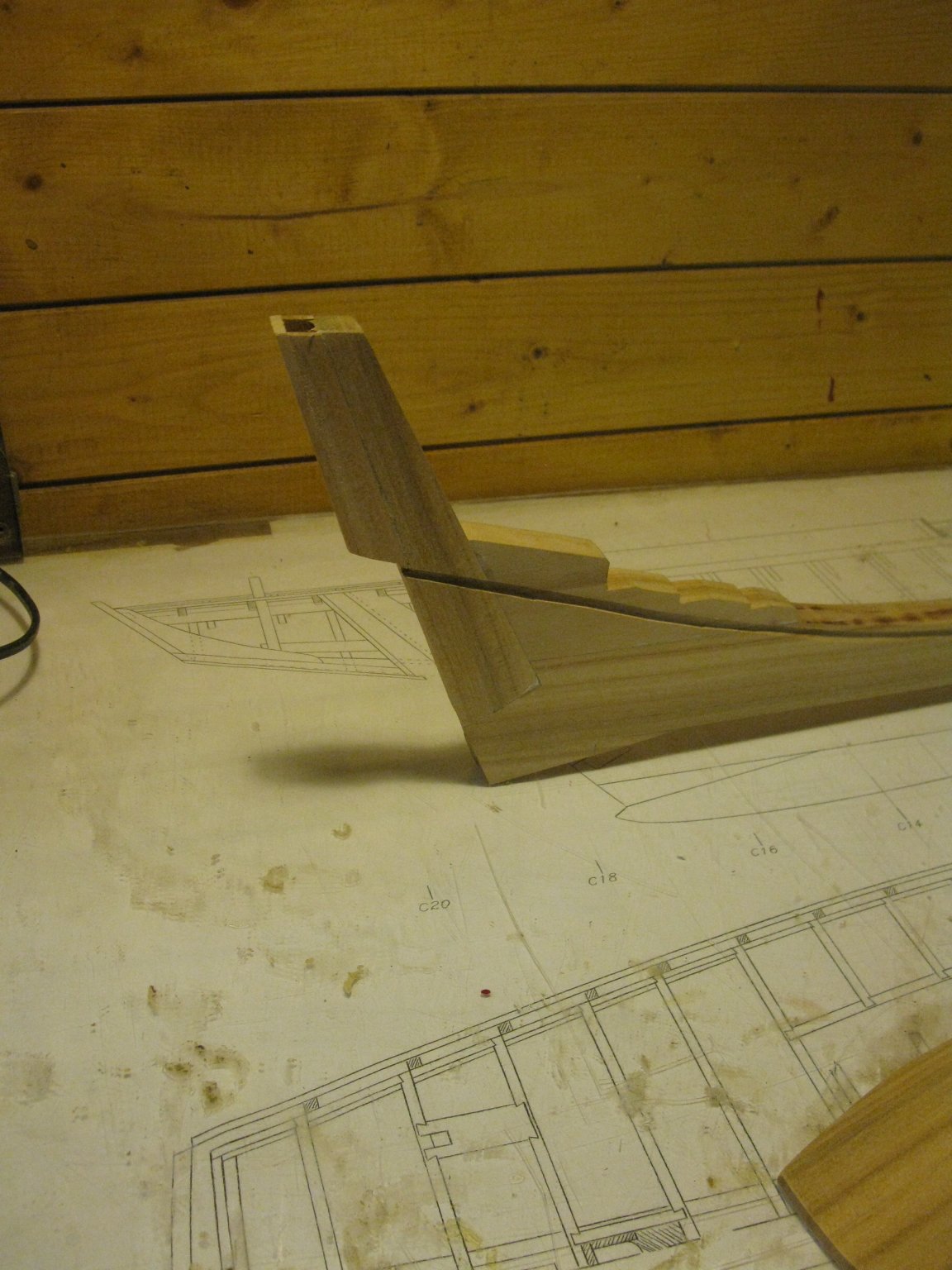
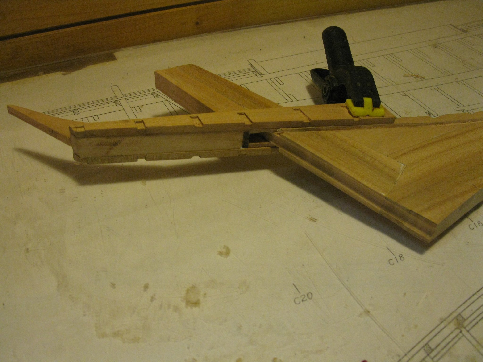
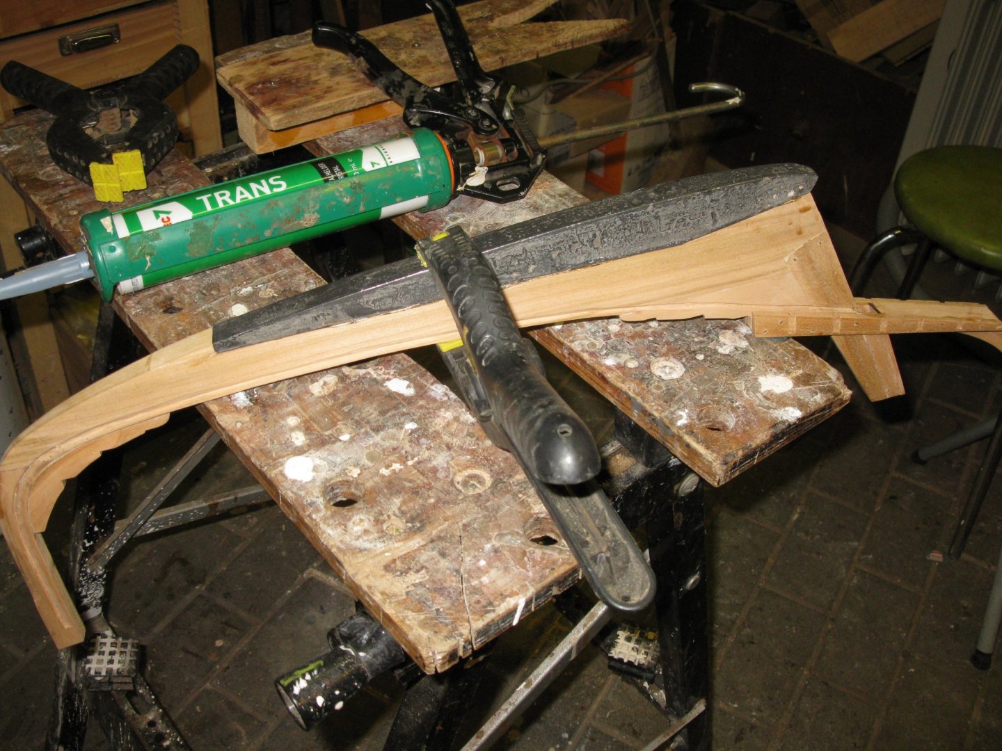
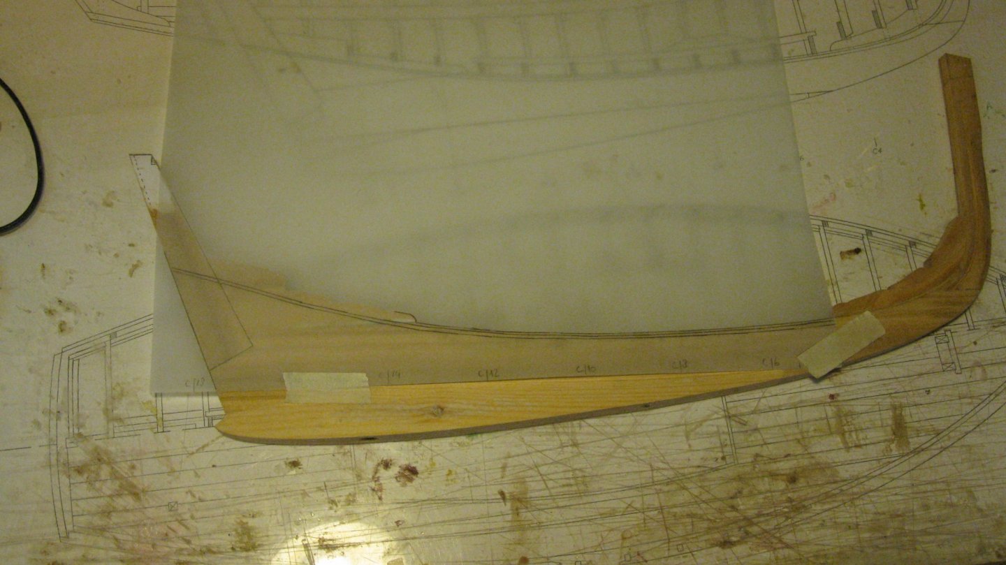
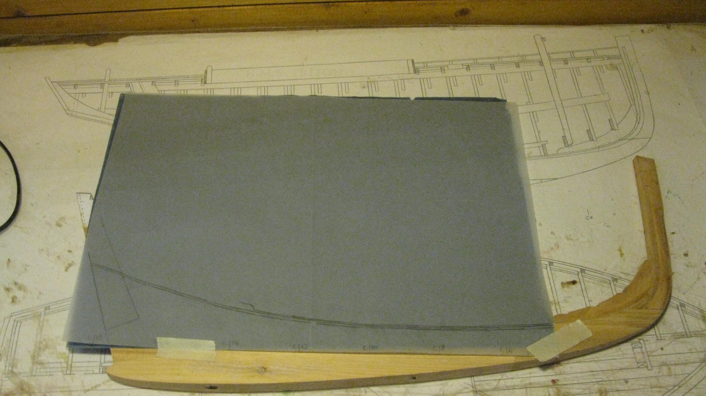
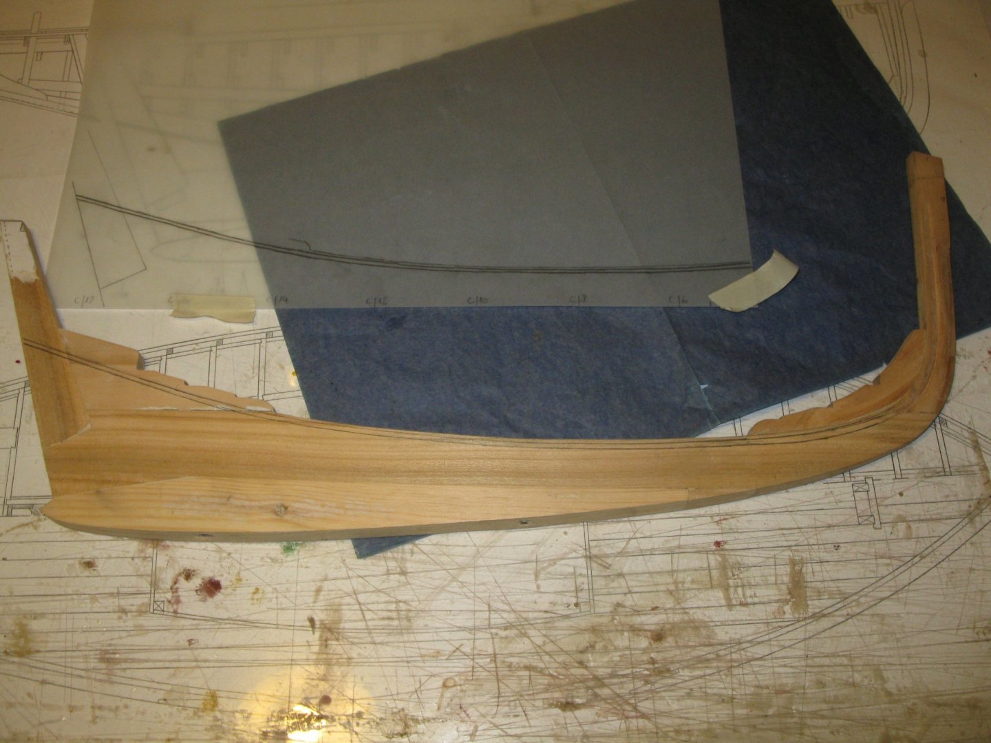
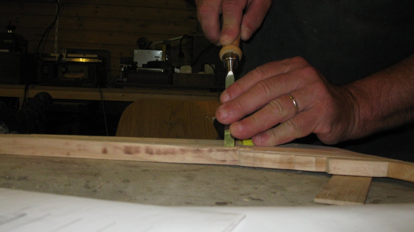
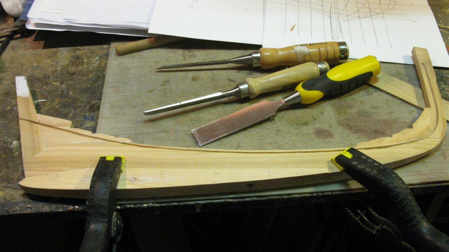
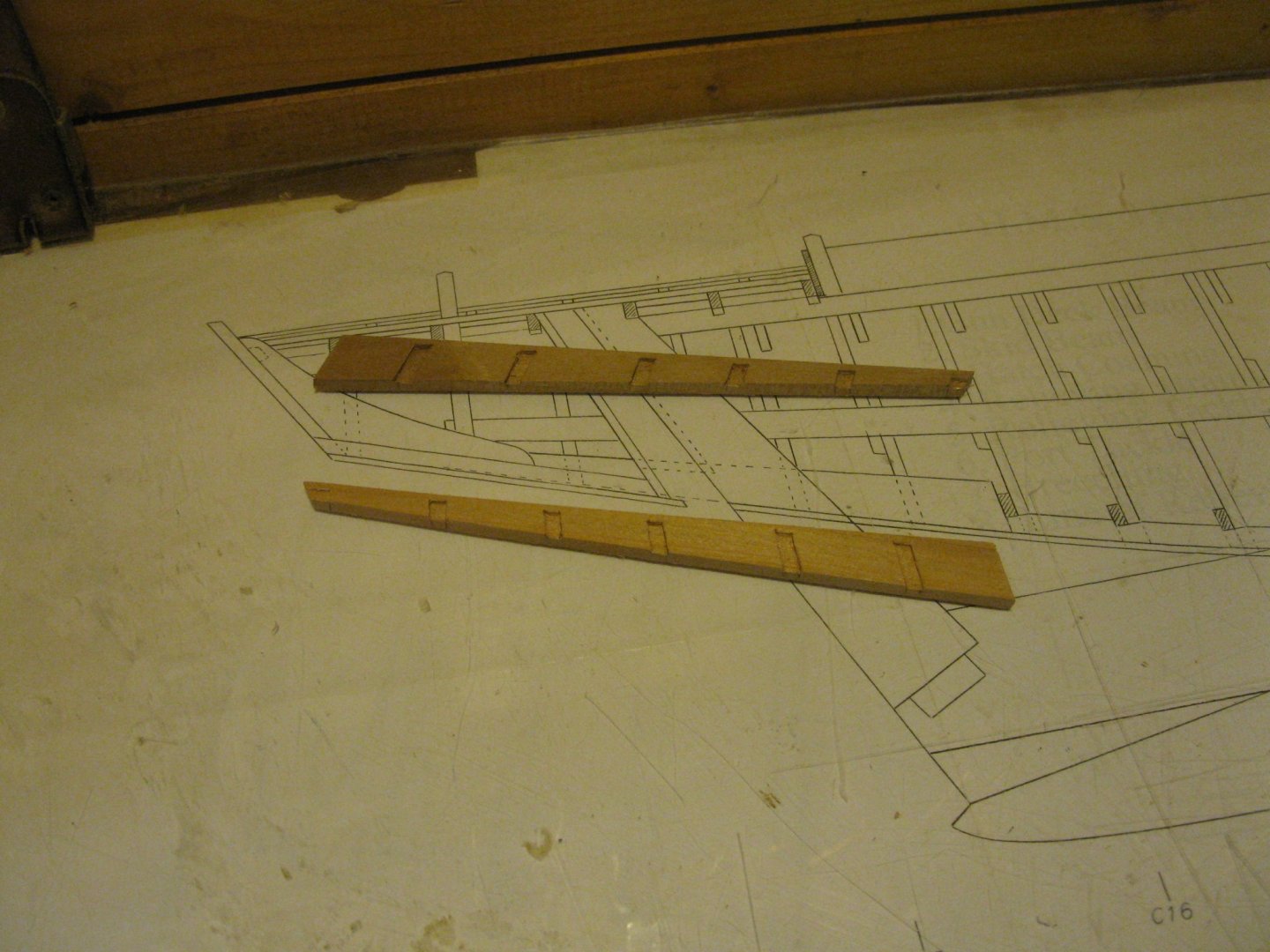
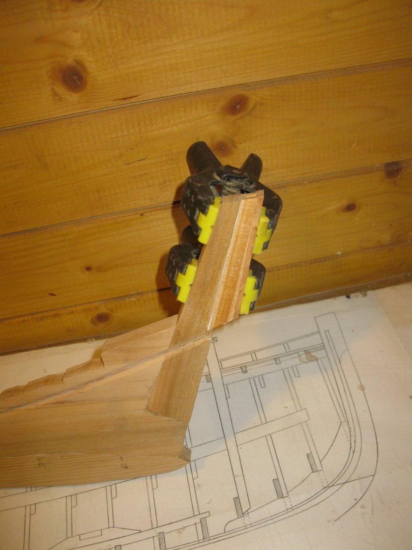
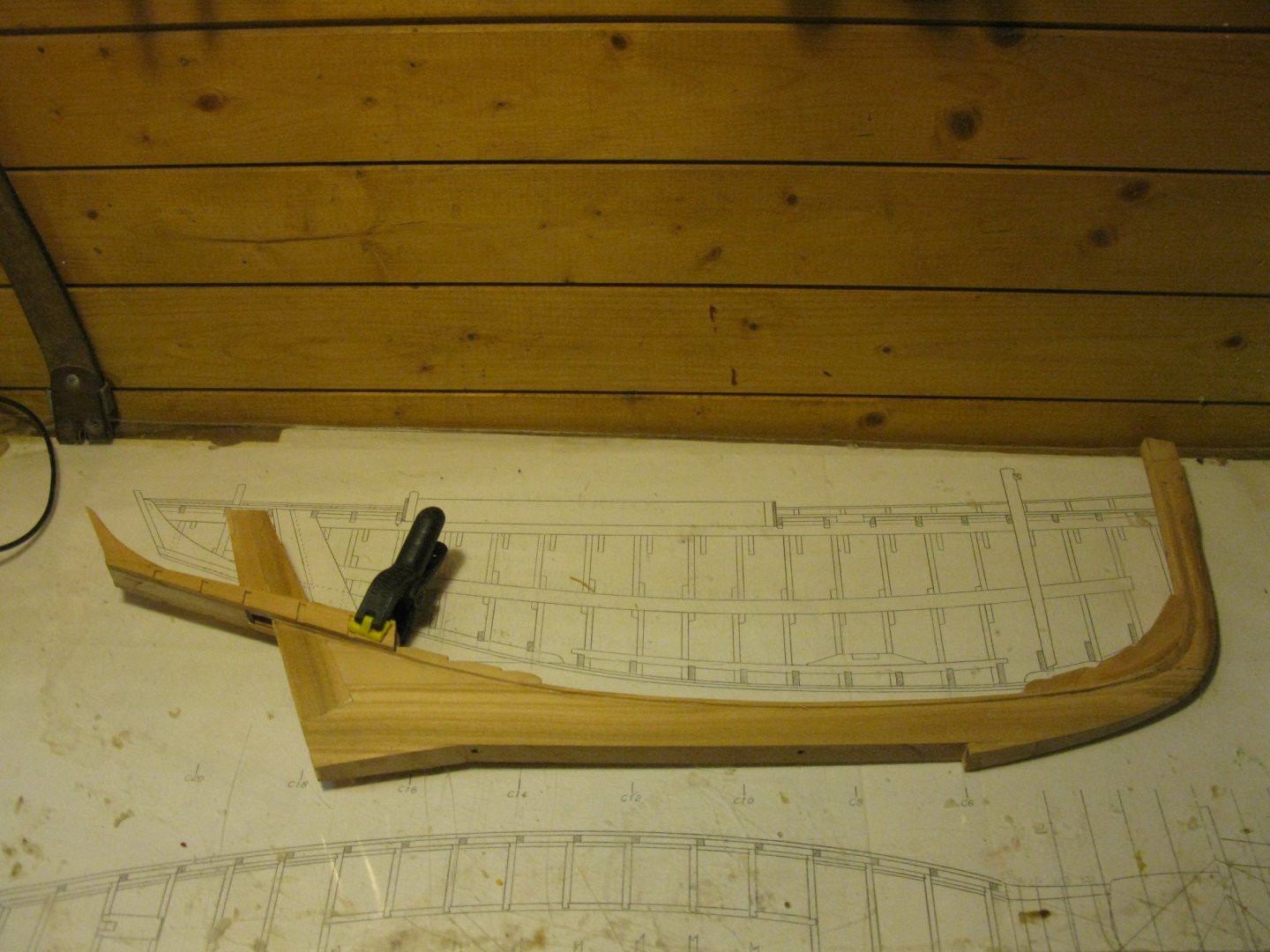
The notch for the garboard stroke is to be cut in the keel. I draw the shape of the notch on a piece of tracing paper and bring it over to the keel with the help of carbon paper. The advantage of tracing paper is: when you turn it upside down you have the drawing in mirror image to draw it on the other side of the keel. Cutting the notch with the chisel. Making the rudder trunk (or is the correct name: 'helm port'?). The transom of the vessel is attached to two arms, in Dutch they are called 'achterloop' or 'jambekken', I believe that the English term is 'counter timber'. Making the counter timbers: The counter timbers attached to the keel:


-
Welcome back, Aviaamator. Wish you a speedy recovery.
-
Jorge, your carving work is outstanding.
-
Nice repair on the prow, Peter.