G.L.
-
Posts
1,553 -
Joined
-
Last visited
Content Type
Profiles
Forums
Gallery
Events
Everything posted by G.L.
-
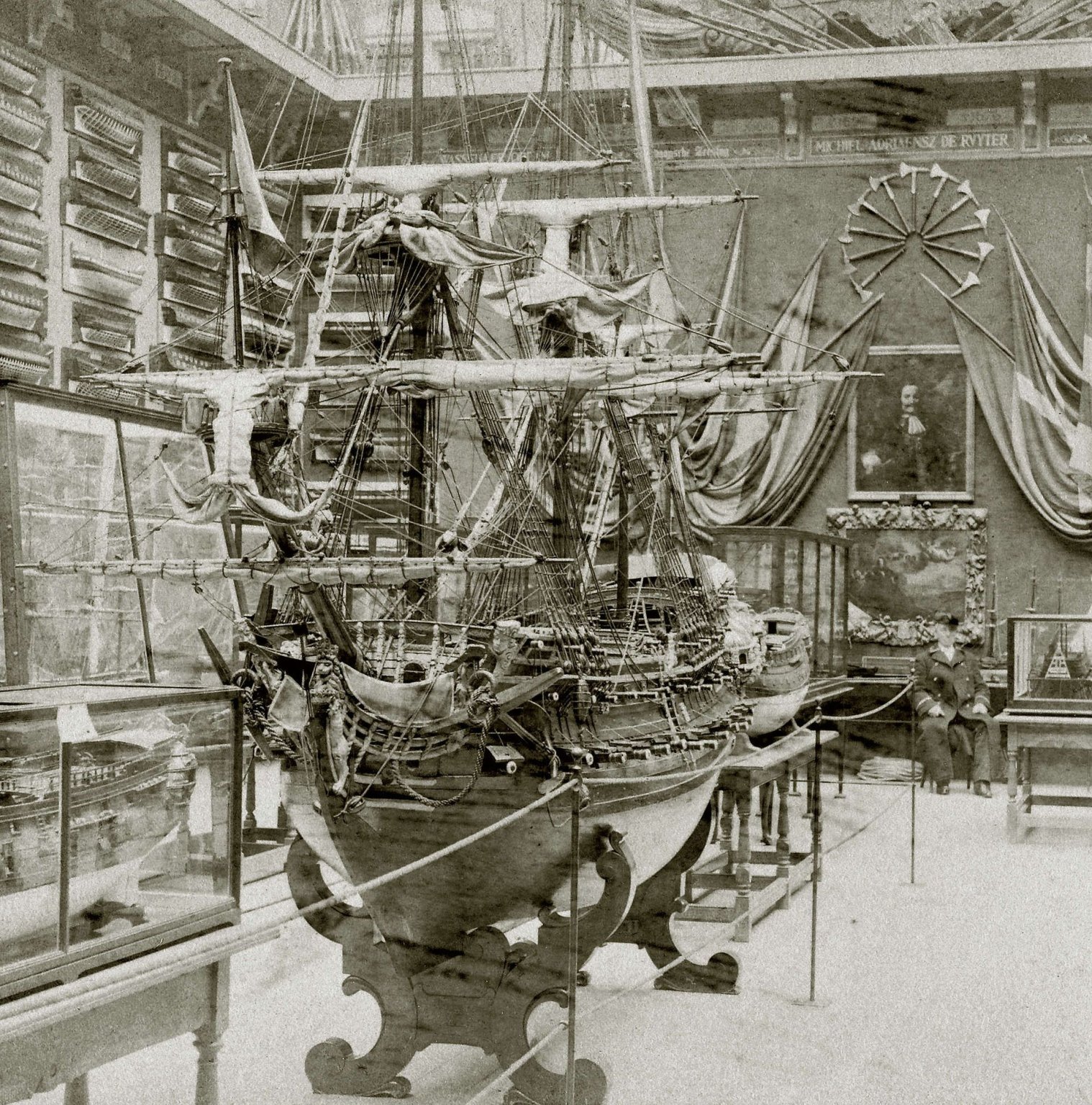
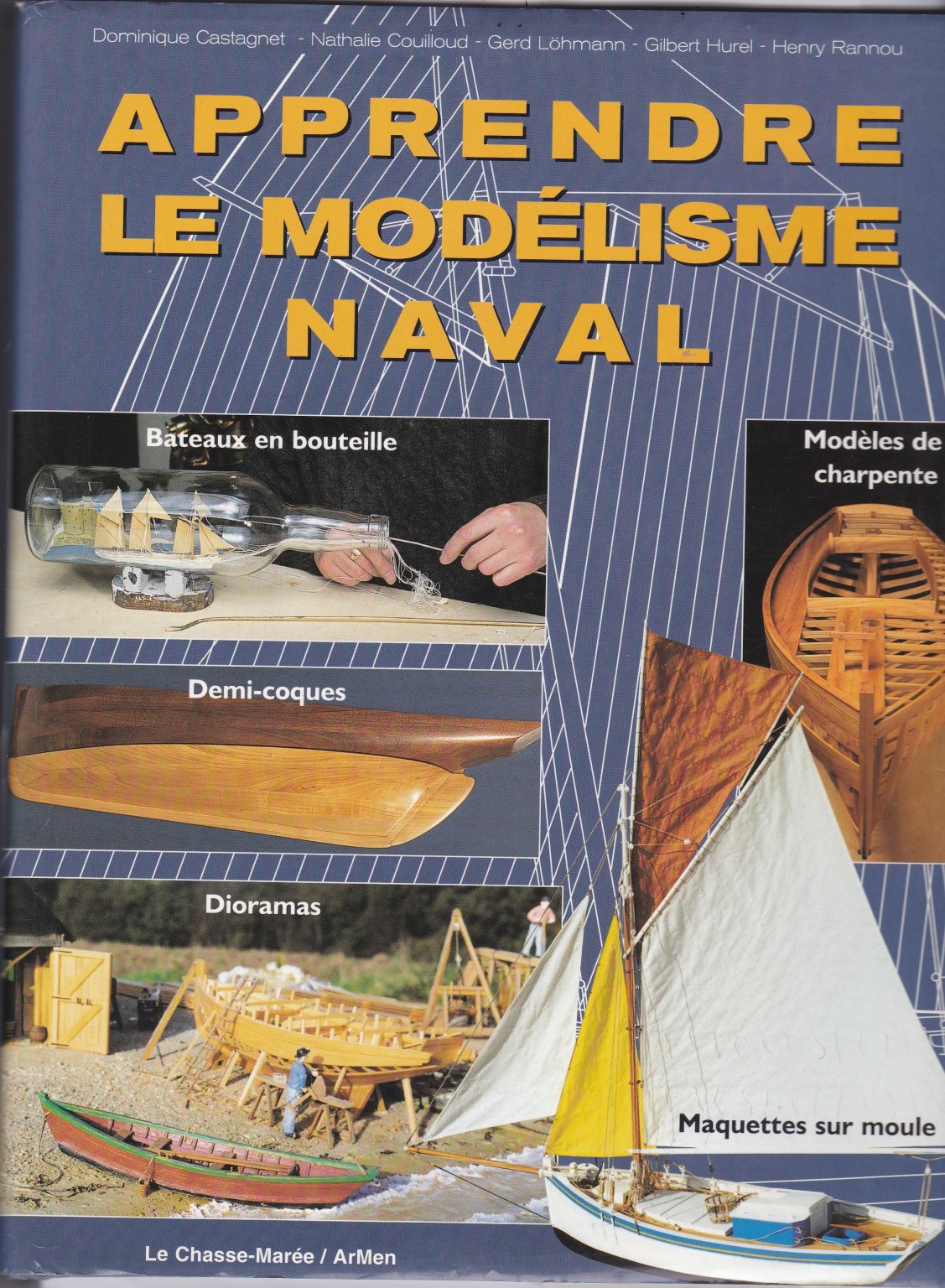
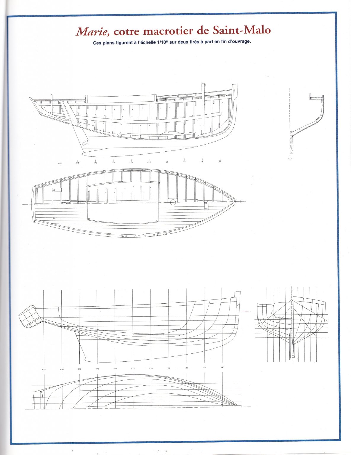
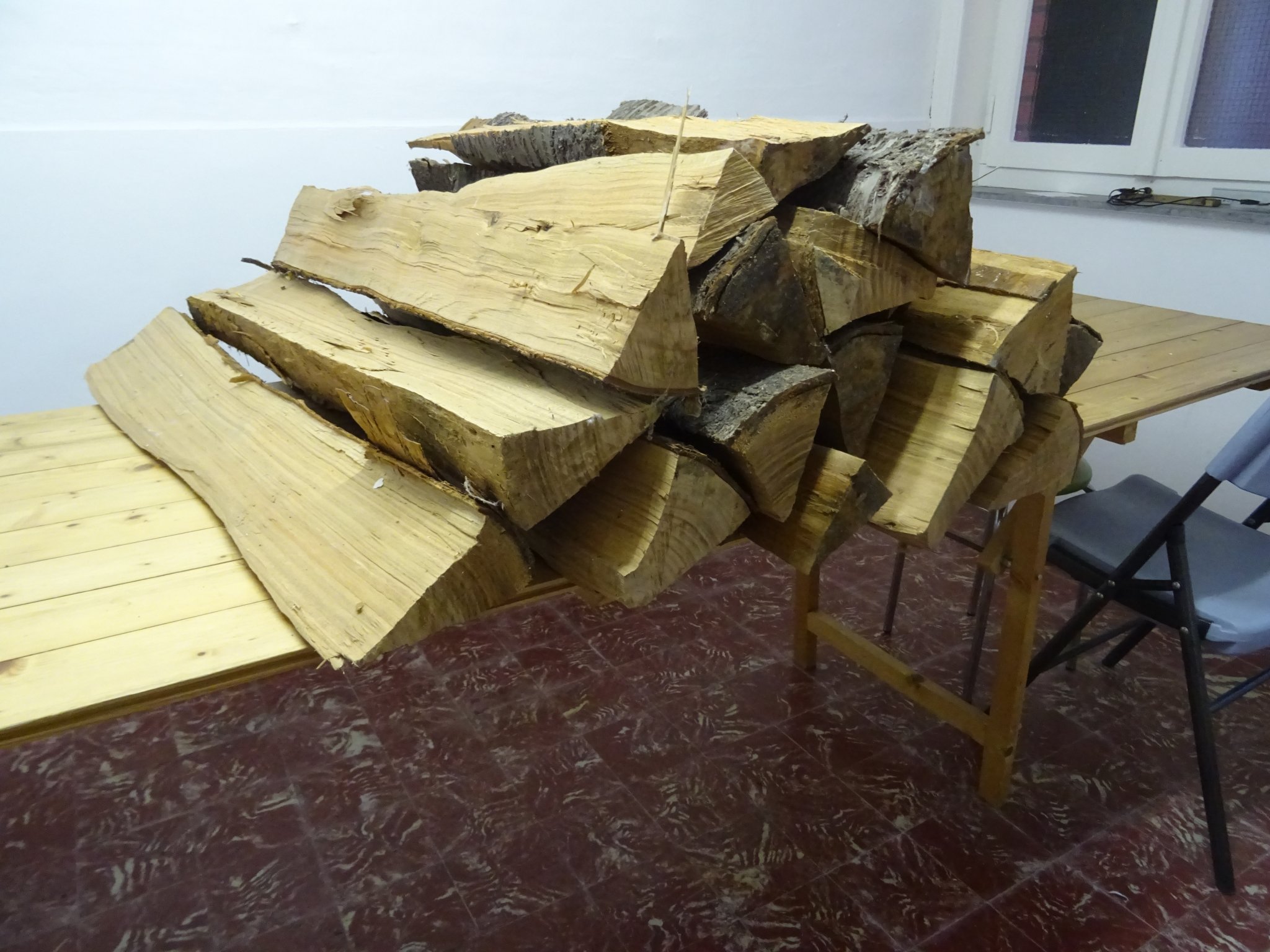
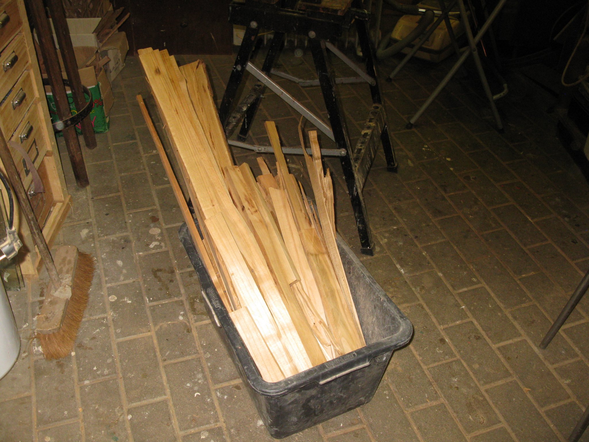
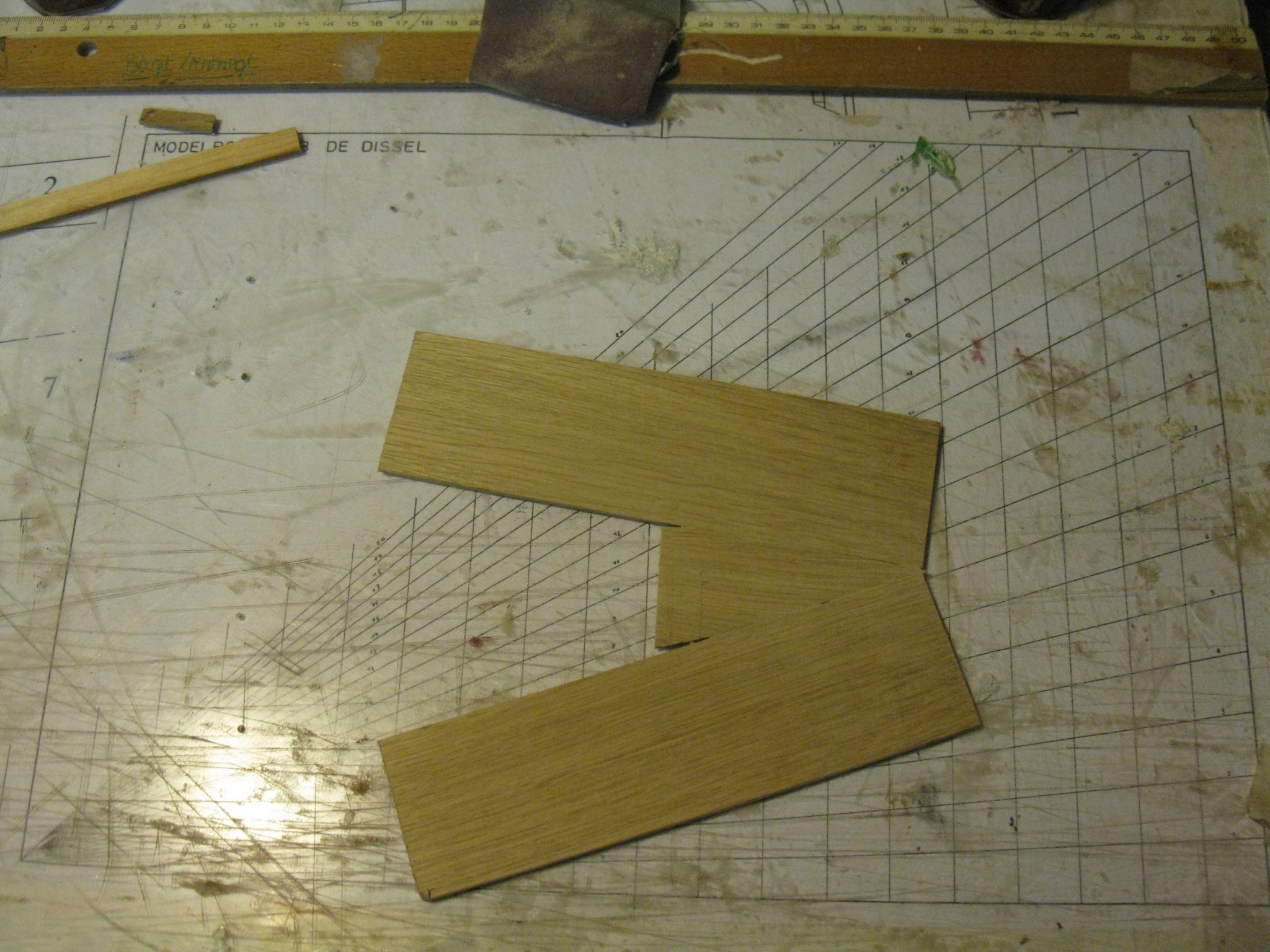
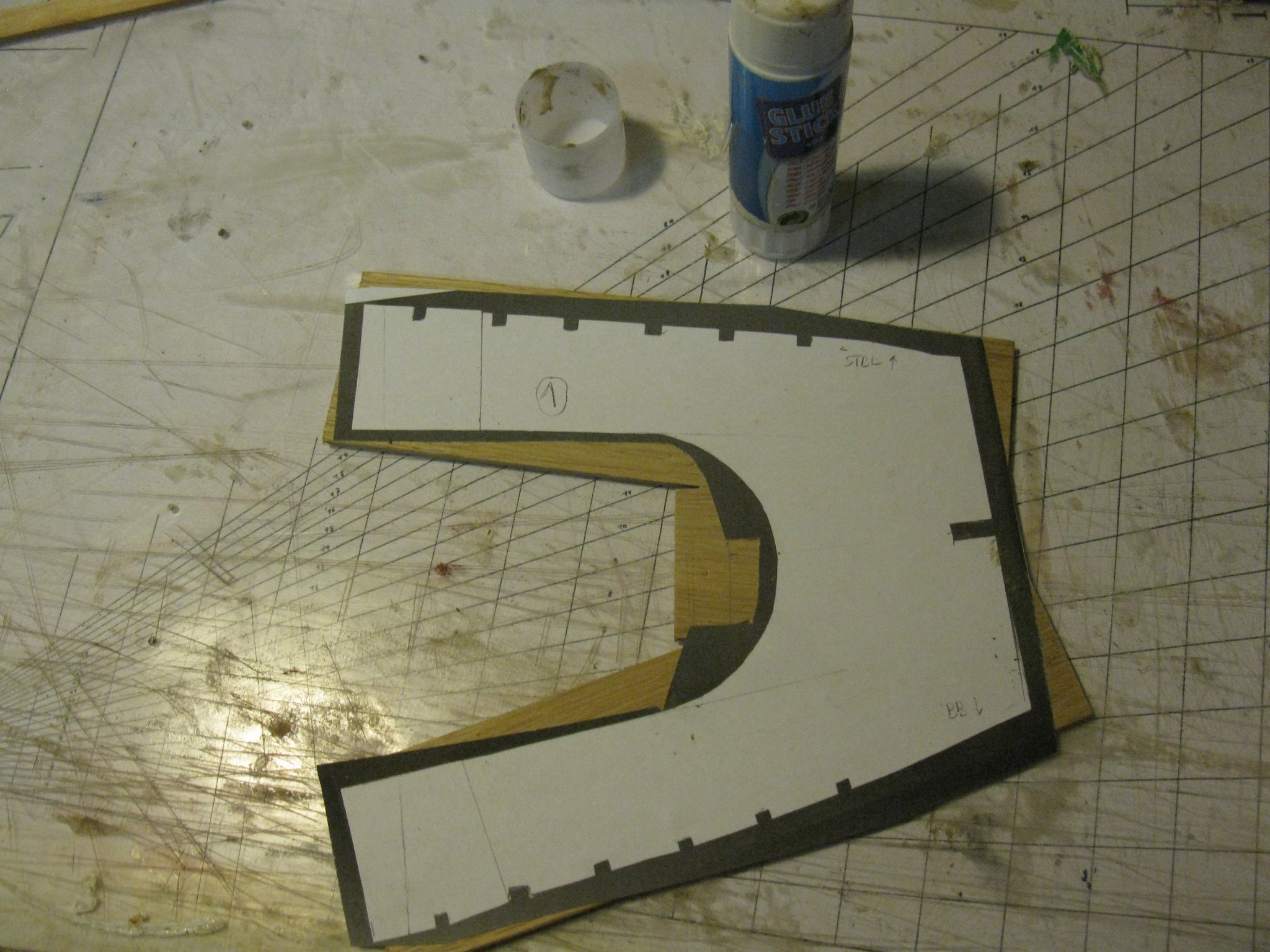
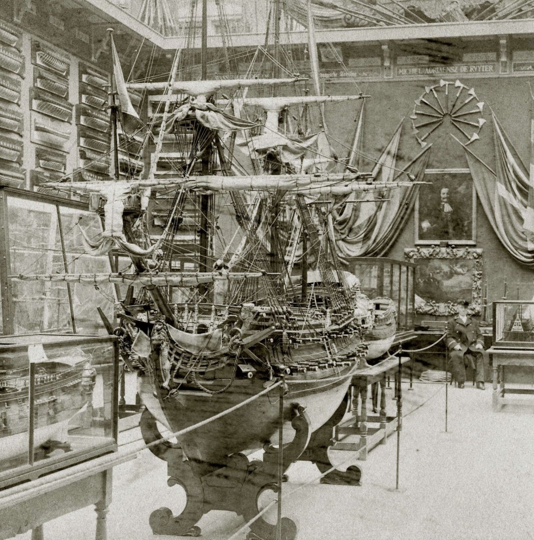
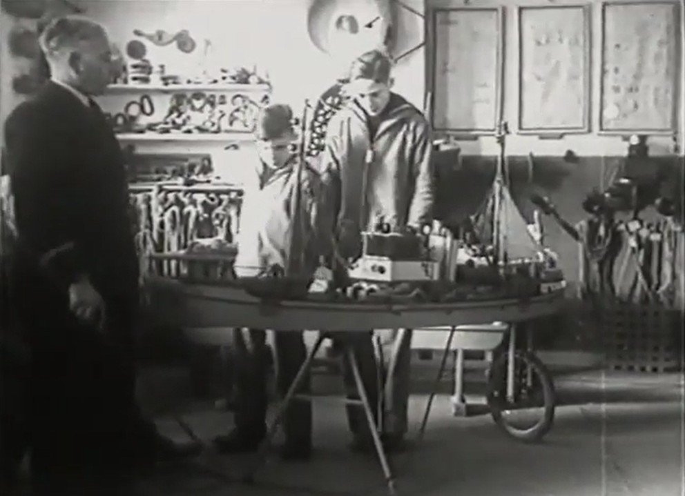
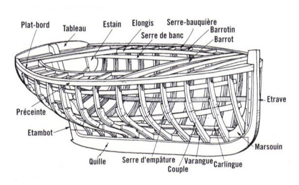
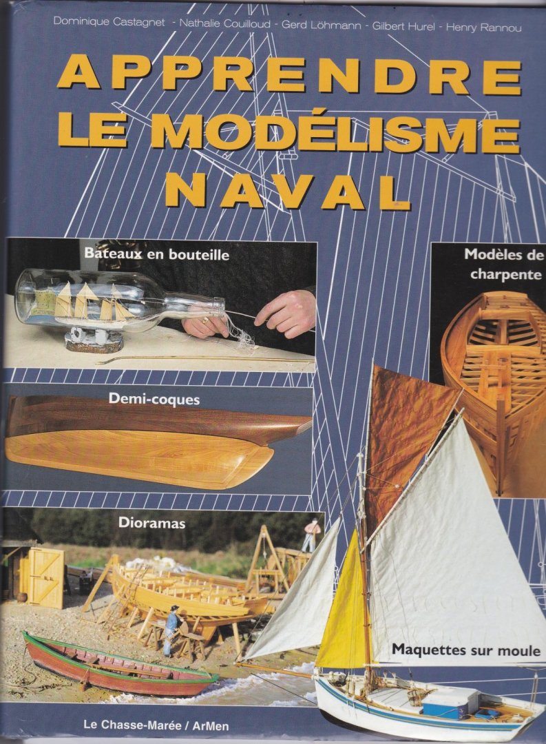
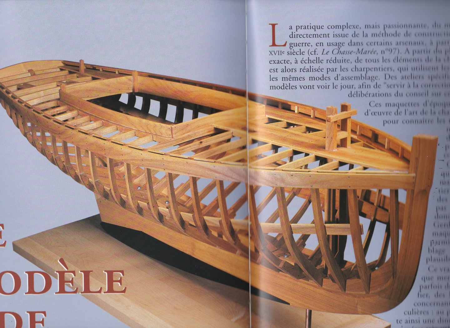
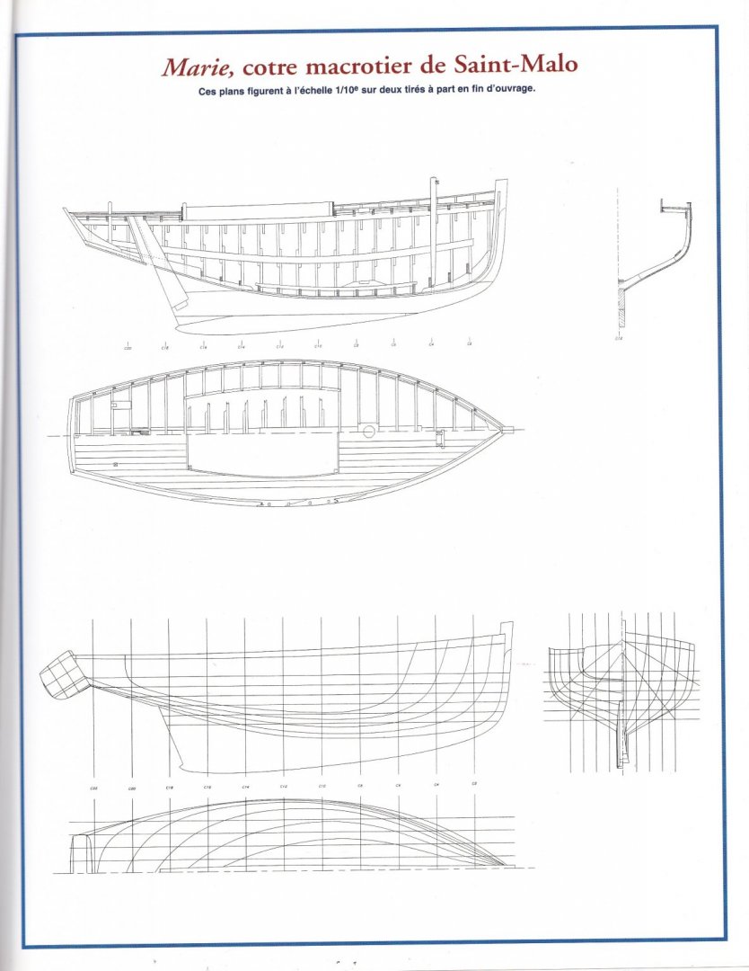
 In August, after finishing my smack cross section, I started a new project. The first series of pictures are sorted now, it is time to start with the log of this new scratch project. Introduction Since ages, the ship model was the ideal tool to show how a vessel fits together. Ship builders used models to present their new designs to the admiralties. (painting 'A New Ship for the Dutch' John Seymour Lucas) In the 19th and early 20th century they were very suitable for museums to show to the general public how live on board of a ship was. (Picture of the old Rijksmuseum in Amsterdam, borrowed from the website of the Rijksmuseum). And not least, the ship model was used as a didactic tool in maritime education. (Source of picture: fishermen's orphans during nautical education, 'IBIS' Orphan school in Ostend during the 50ties. Screenshot from archive movie 'Koninklijk Werk IBIS') I had my first naval training in the mid-seventies. In that time the era in which the ship model was a current didactic tool was already past. The ship model was replaced by slides on overhead projectors and video. Nowadays maritime education centers use Power point, smart boards, digital simulators, and all kind of virtual tools. But I still remember that the Mine Warfare School in Ostend had a series of beautiful dioramas to demonstrate all the different types of mine sweeping gear, in the seamanship classroom in the Naval Education Center they had all kinds of models of the rigging for replenishment at sea. We learned the maritime buoyage system with models of the buoys. During sailing classes we learned the different parts of the sail boat with the help of a 1/5 scale model of the Caravelle sailing boat. All those fine didactic models are vanished. I suppose that a lot turned into dust in cellars and attics. Some disappeared probably to private collections and hopefully some are preserved in museums although I didn't see back a lot of them. Up to now I have built some didactic models, two cross sections and a full framed fishing sloop with one side left open. From nostalgic motive I want to build a pure educational model. It will be a old fashioned school model, intended to learn a landlubber (or a new naval recruit) the different parts of a boat. The image below shows more or less what I have in mind: making a model of a stripped boat and naming all the parts of it. (drawing from 'Le Chasse Marée') I find a suitable design for my project in the book 'Apprendre le modelisme naval' (a publication of Le Chasse Marée). In the chapter 'Le modèle de chartente' (the model on frames) the boat carpenter Gerd Löhmann explains how to make a model on frames. The chapter is a description of the build of the mackerel cutter 'Marie', a small sailing fishing sloop of the type which was used along the Breton coast (France) before World war II. Gerd Löhmann built his cutter just like I would like to be my didactic model (Picture from the book 'Apprendre le modelisme naval'). The book contains also the detailed plans of the vessel on scale 1/10. The real vessel was built in 1928 and was 6.86 m long, so the model will be ±69 cm long. I will build it in cherry (Picture from the book 'Apprendre le modelisme naval'). Some time ago I got a few stumps from the trunk of a cherry tree that an acquaintance cut down in his garden. I have split the stumps into sawable pieces an stowed them away on a dry space. That is the wood I will use for my instruction model: Some pieces sawn into planks, ready to be planed to the necessary thicknesses. To finish this post, a word about the layout of this building log. I would like to make this project not simply an instruction model, but also a lexicon and encyclopedia about wooden shipbuilding terms. So, I will work in three phases: first the boat model, then the lexicon and finally the encyclopedia. My log will follow this sequence and will be build up in three chapters: I. The Boat II. The Lexicon III. The Encyclopedia Now I am ready to start. The keel will be laid in my next post. I hope I will be able to captivate you with this new project.
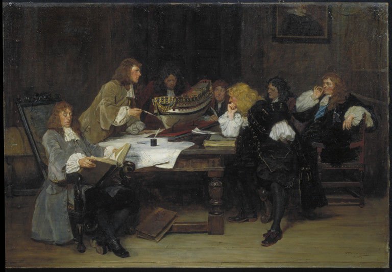


- 168 replies
-
- 26
-

-
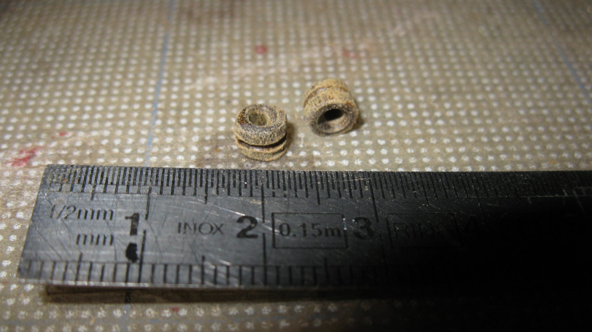
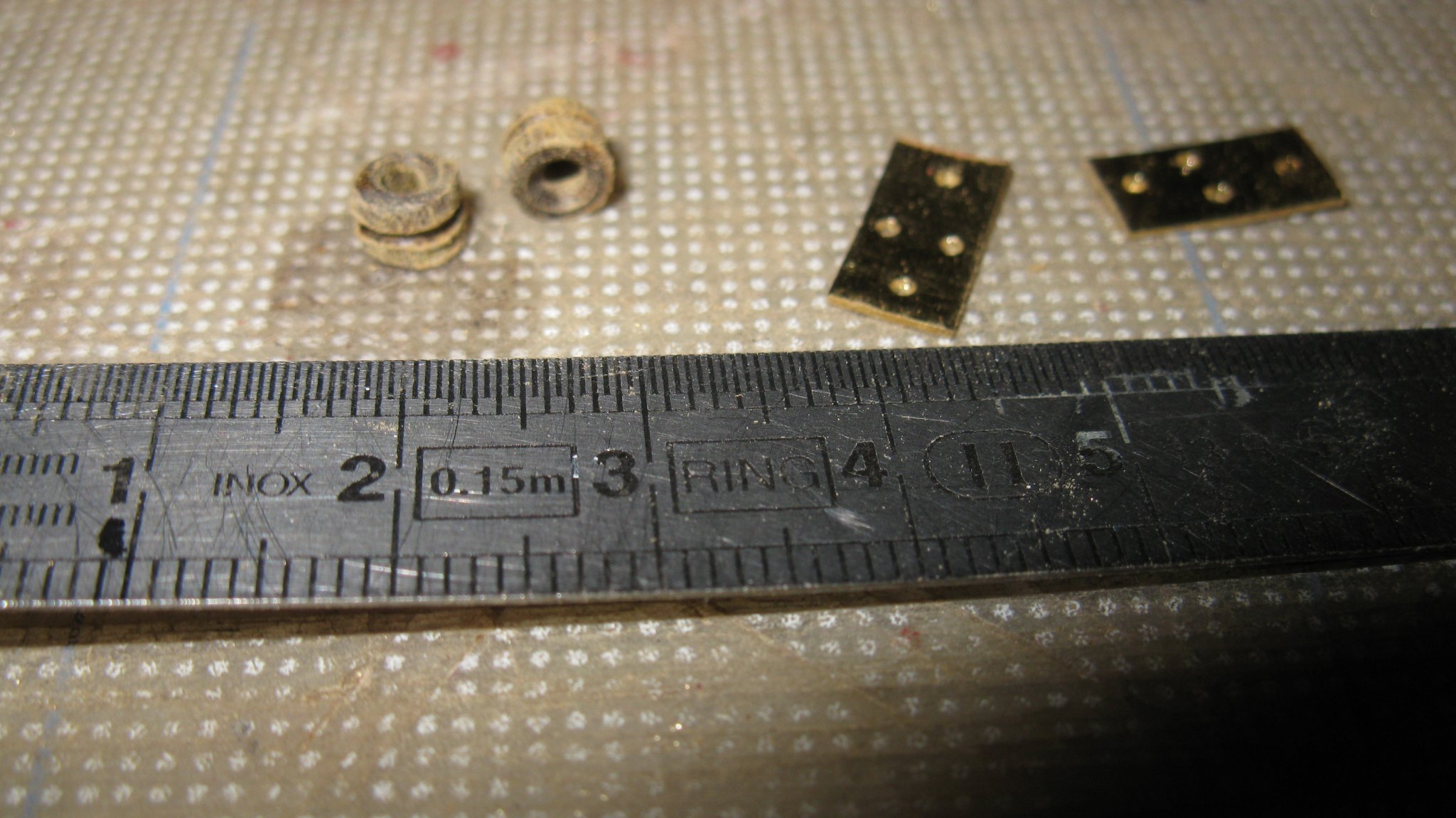
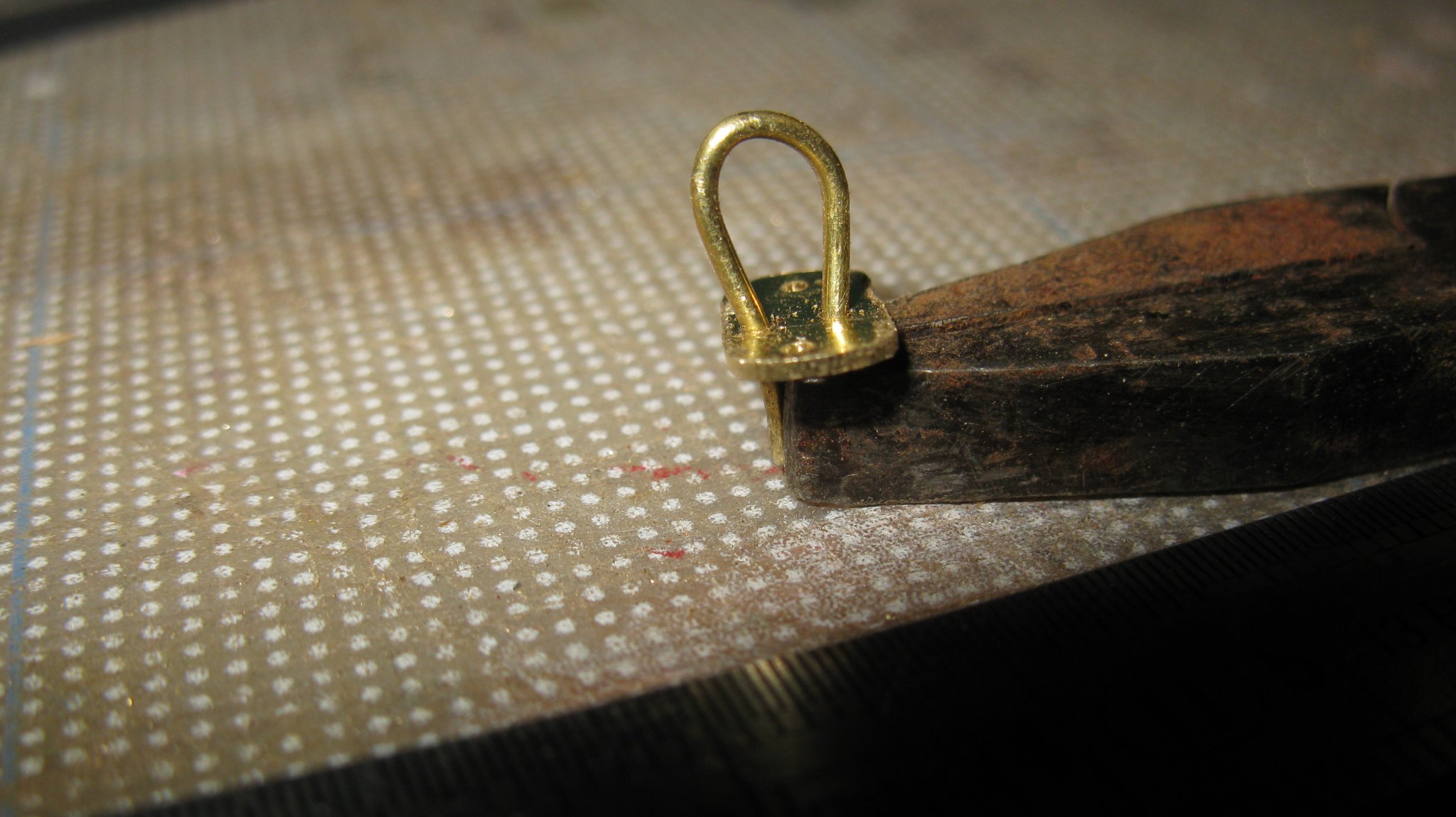
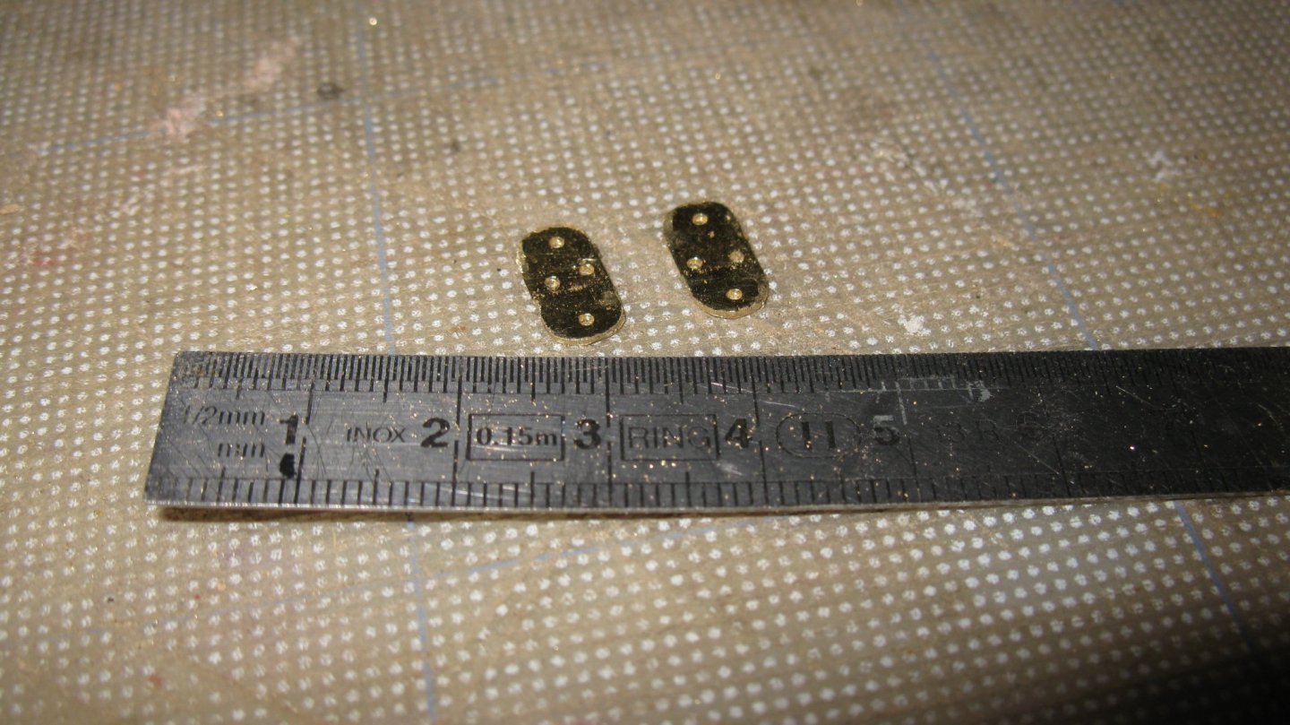
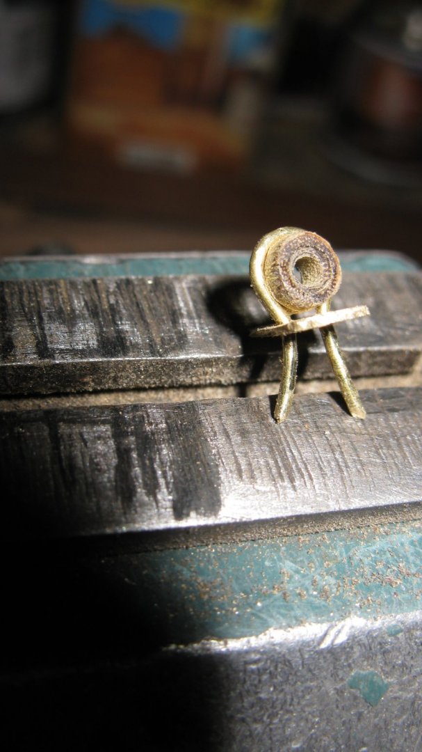
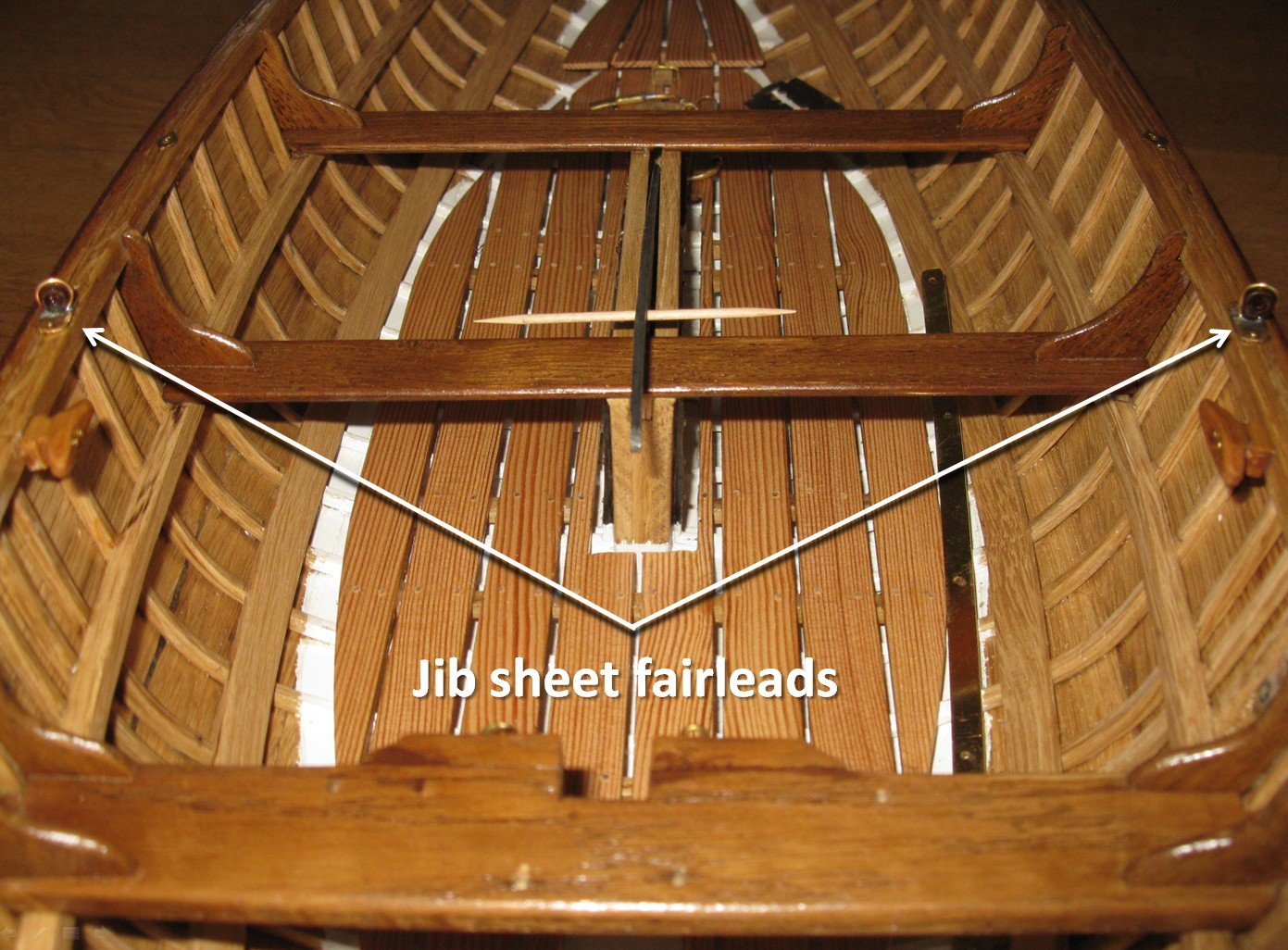
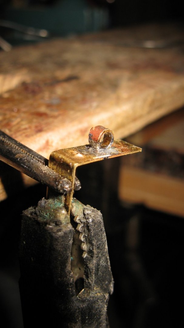
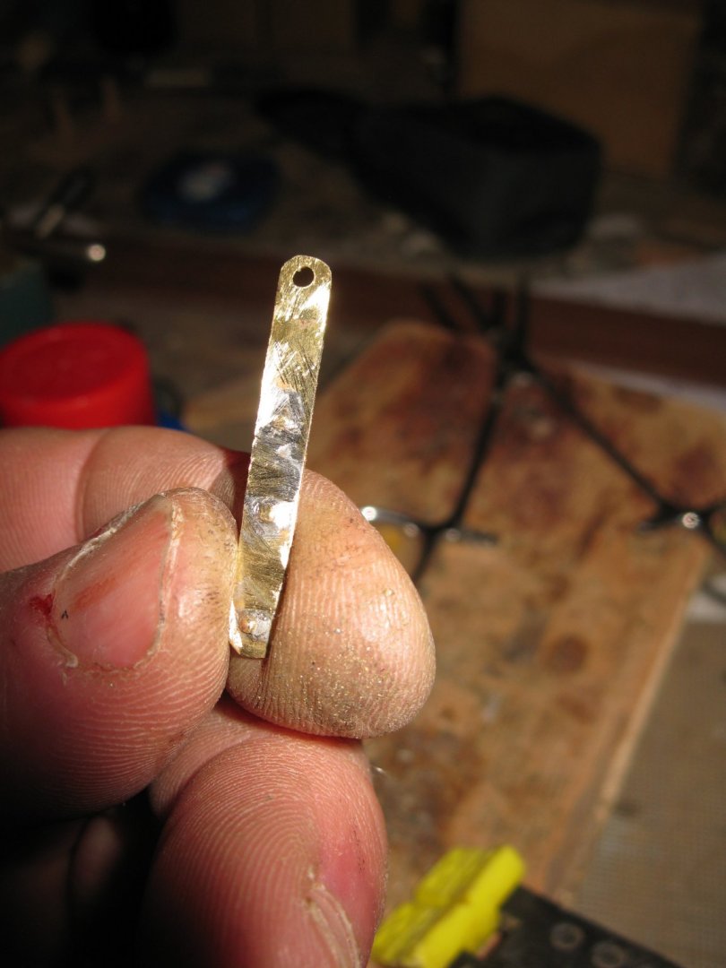
10.3 The jib sheet fairleads The eyes of the fairleads are tuned from hard wood on the lathe. I saw and file two brass plates with four holes. A brass ring is holding the wooden ring. The fairleads into their position on the gunwale. Thank you to follow. Thank you for the likes. Till next week!


- 209 replies
-
- 12
-
-
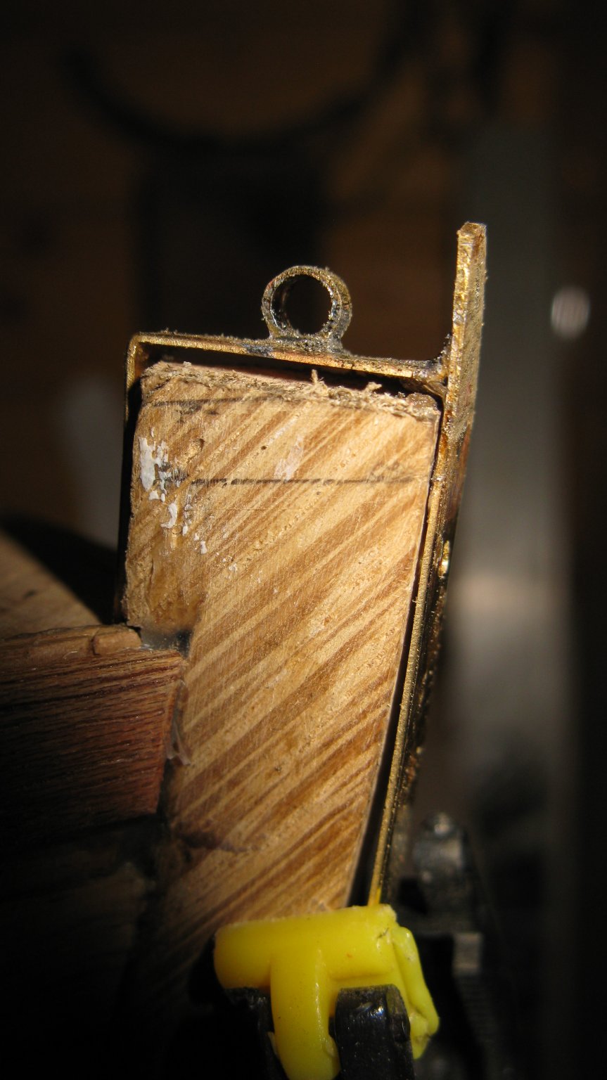
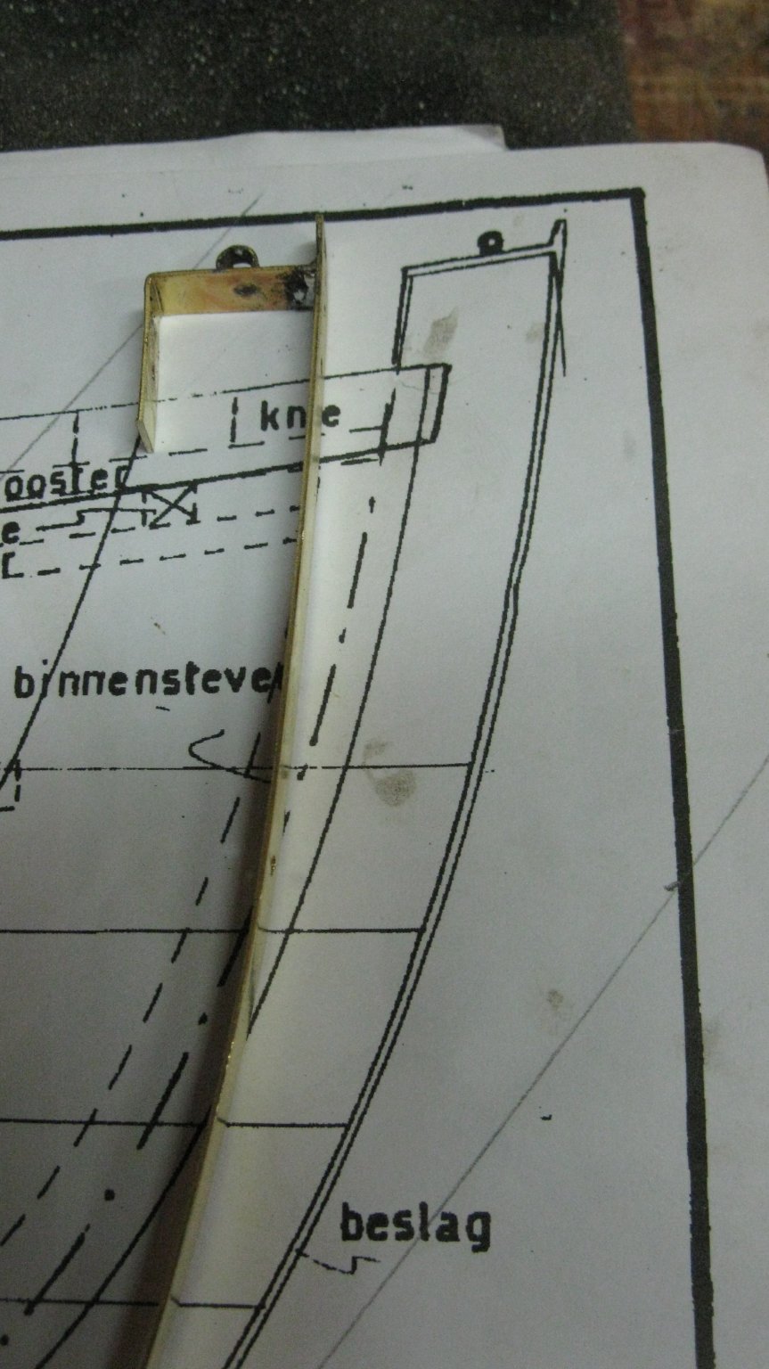
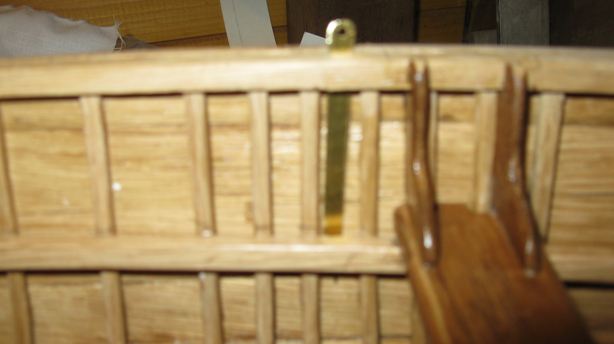
10.2 The bow fitting I make the bow fitting now before the hull is painted because I want the use the actual bow as a template. Soldering an eye on the back piece. Soldering the back piece to the front piece. The bow fitting. It will remain aside until the hull is painted.


-
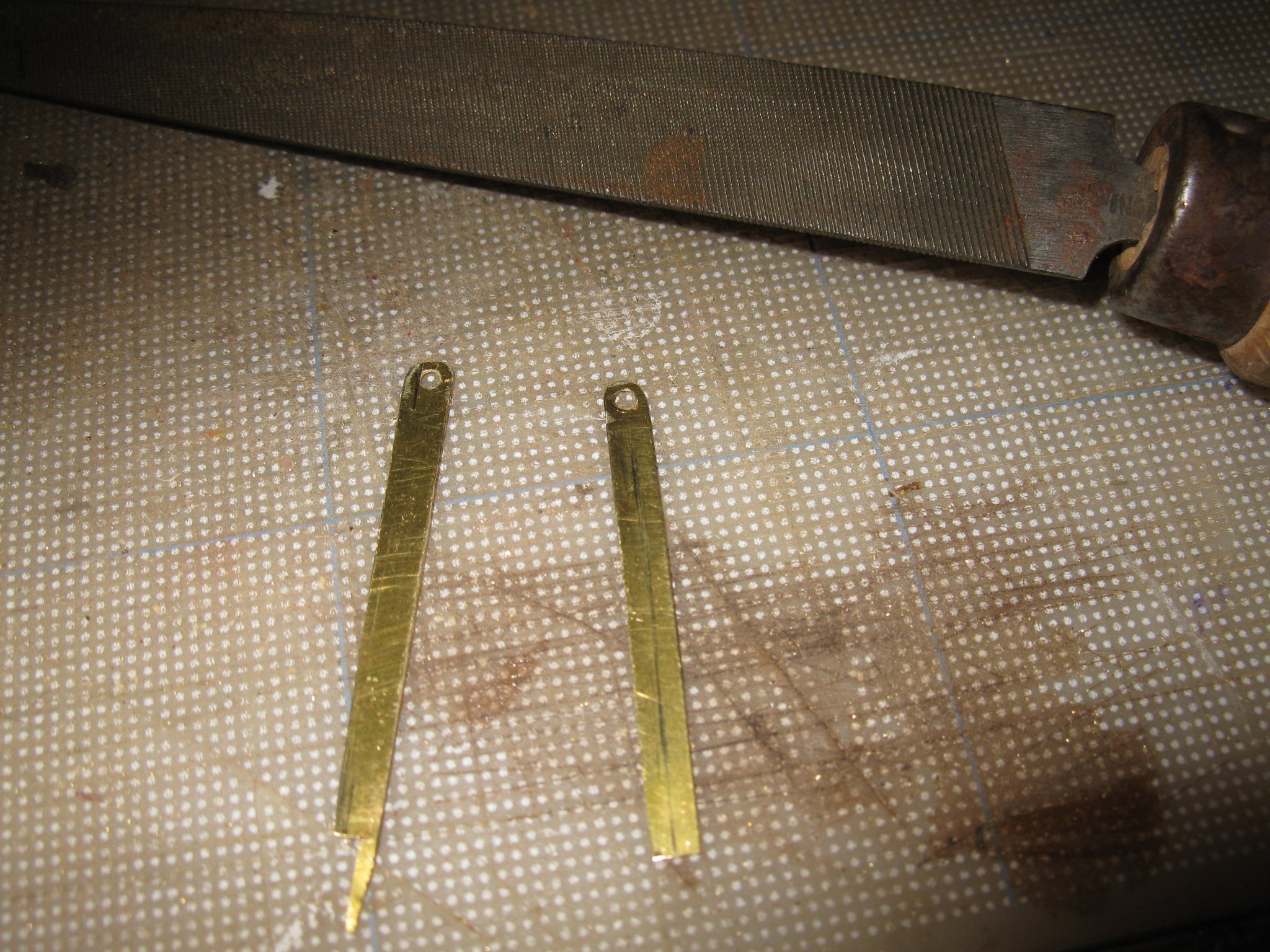
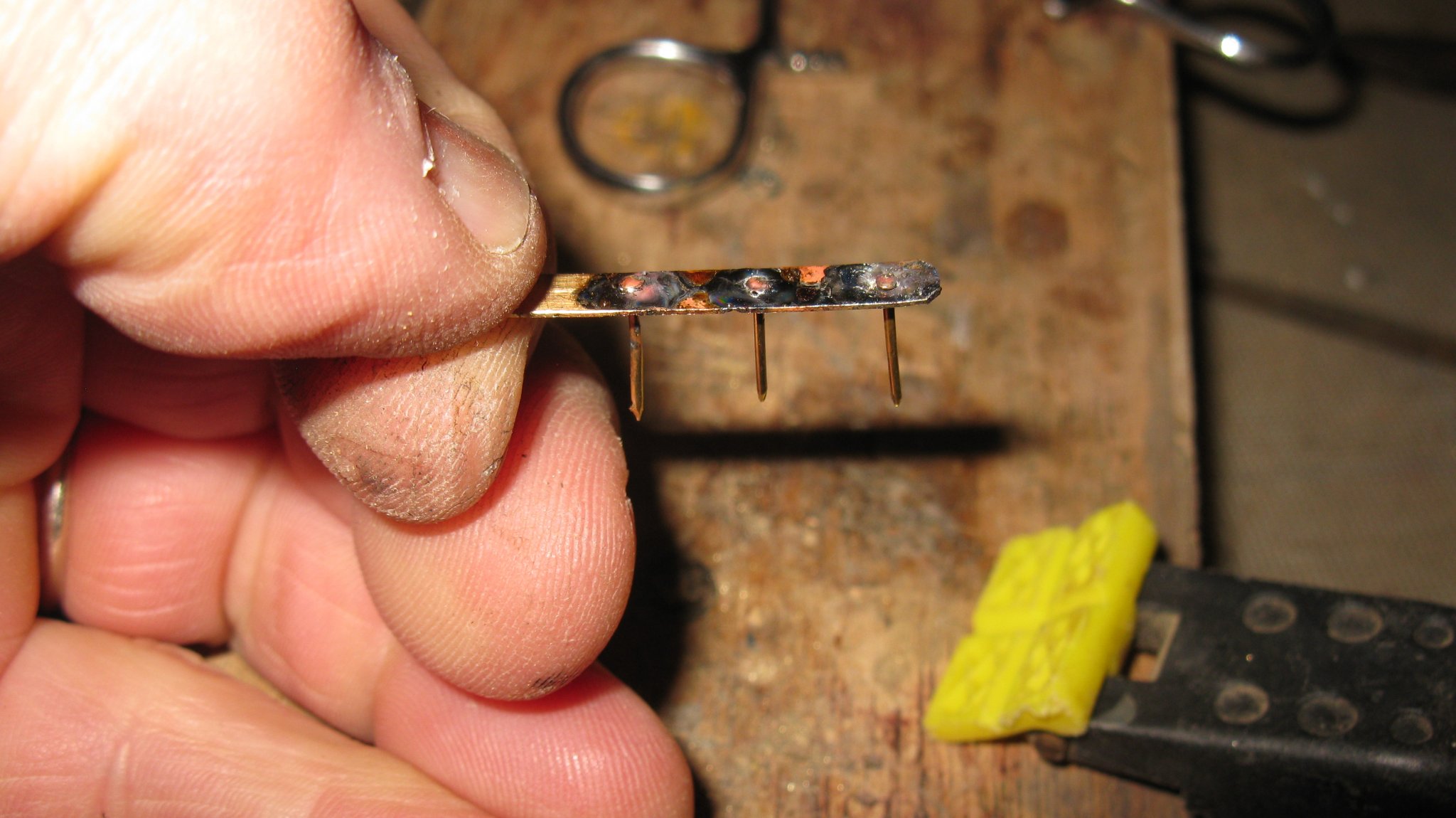
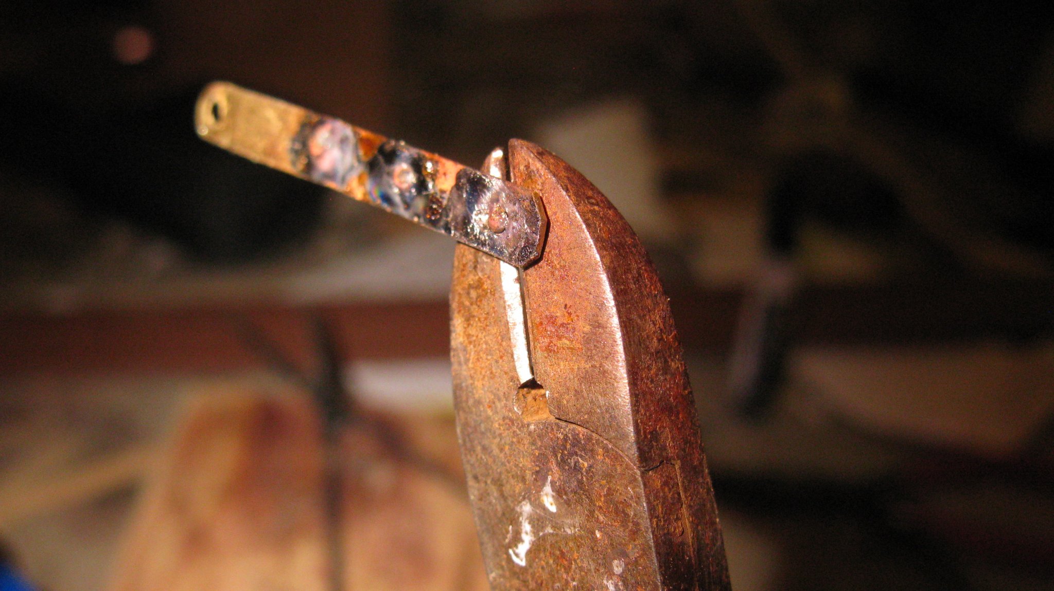
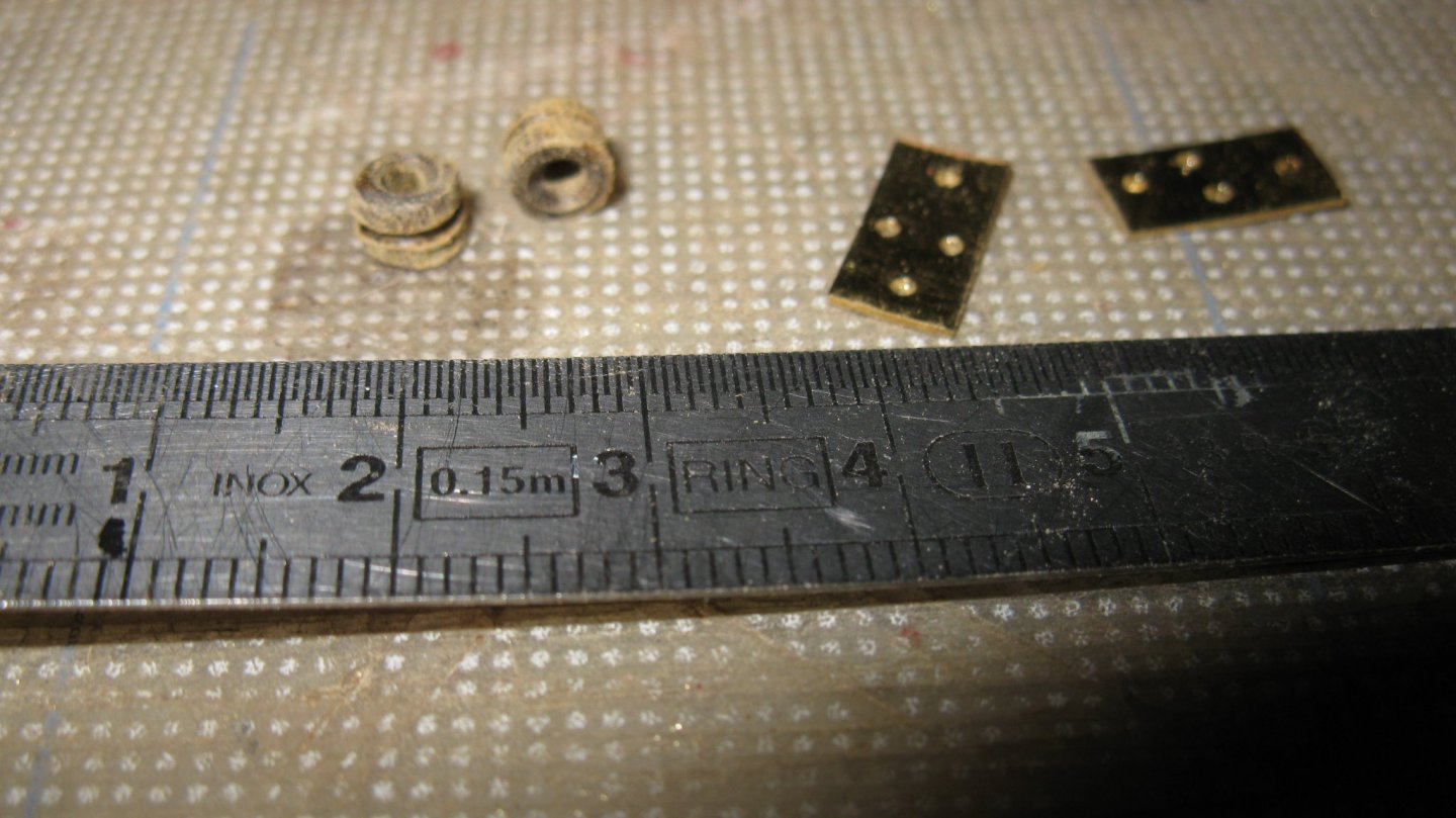
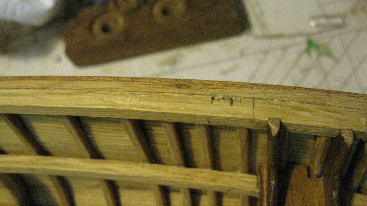
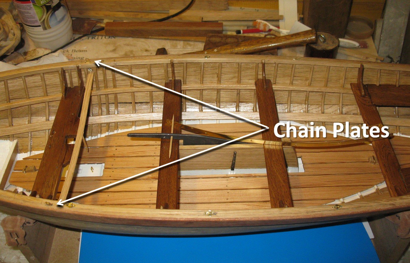
Part 10. The fittings 10.1 The chain plates I make chain plates from two strips of brass. Because it would be difficult to nail the chain plates at the inside of the hull, I solder the nails to the plates The I cut off the excesses of the nails at the back side and file the back of the chain plates flat. It had been easier if Mr Van Beylen wrote it earlier in the practicum that the the chain plates have to go through the gunwale, I could have made the notches in advance. I drill a line of holes in the gunwale and file them out. Fitting a chain plate into its place. And gluing them. The curved board gives some pressure until the glue dried.


-
Vaddoc, I wish you very much success with this project. A 1/10 model of a longboat is certainly something to my liking. I logged in as follower nr9.
-
Part 8.9. Continuation: The inside of the hull. Placing the transom breast hooks. Thank you to follow. Thank you for the likes. And thank you for the constructive comments. Till next week!
-
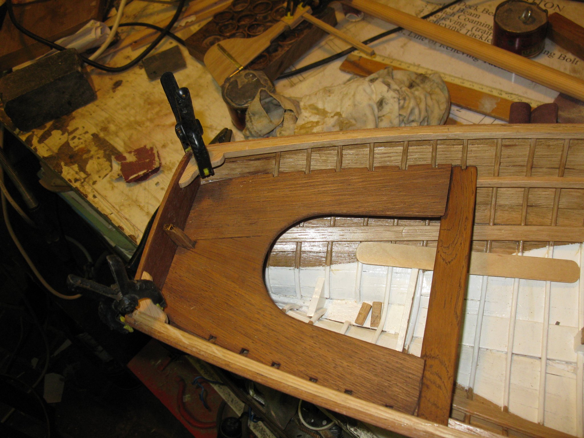
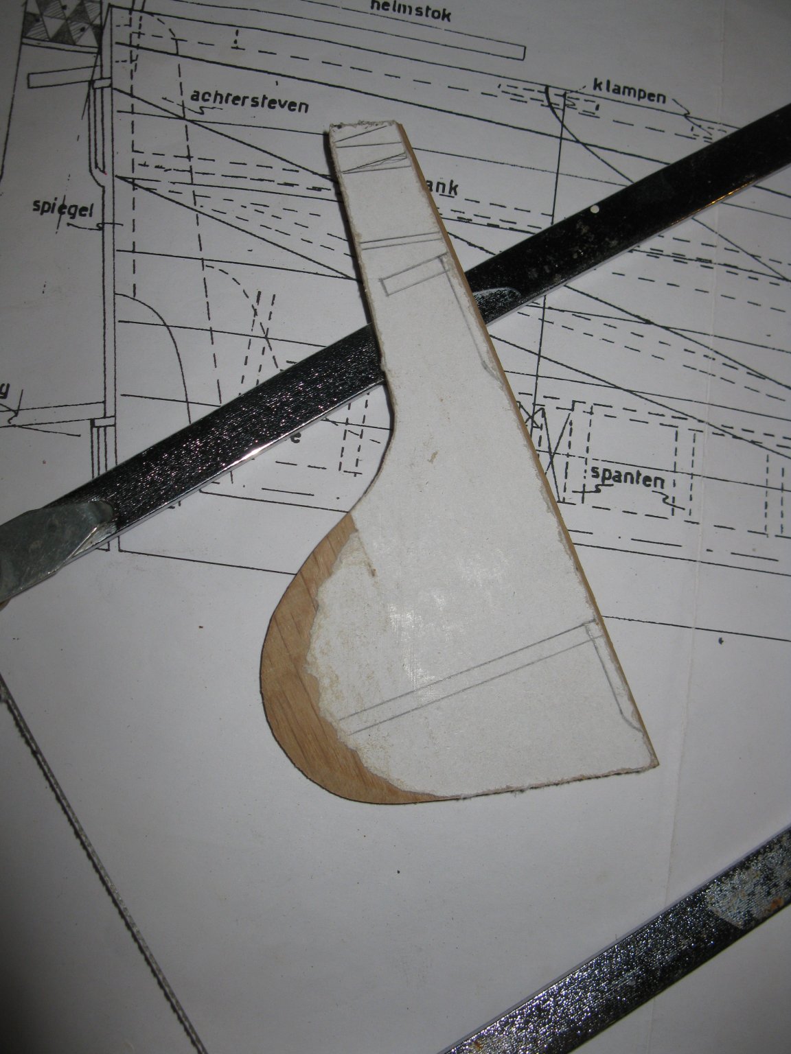
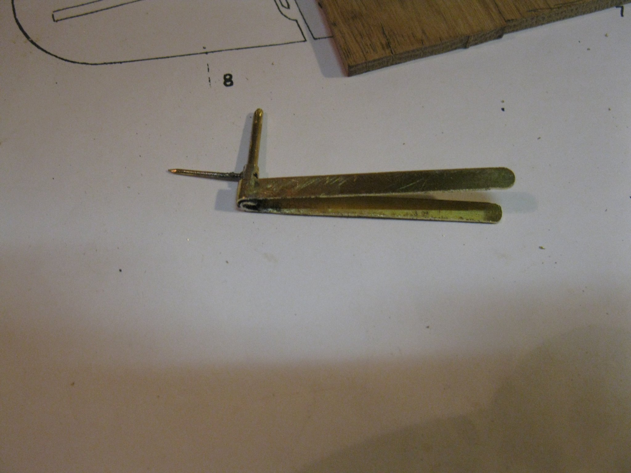
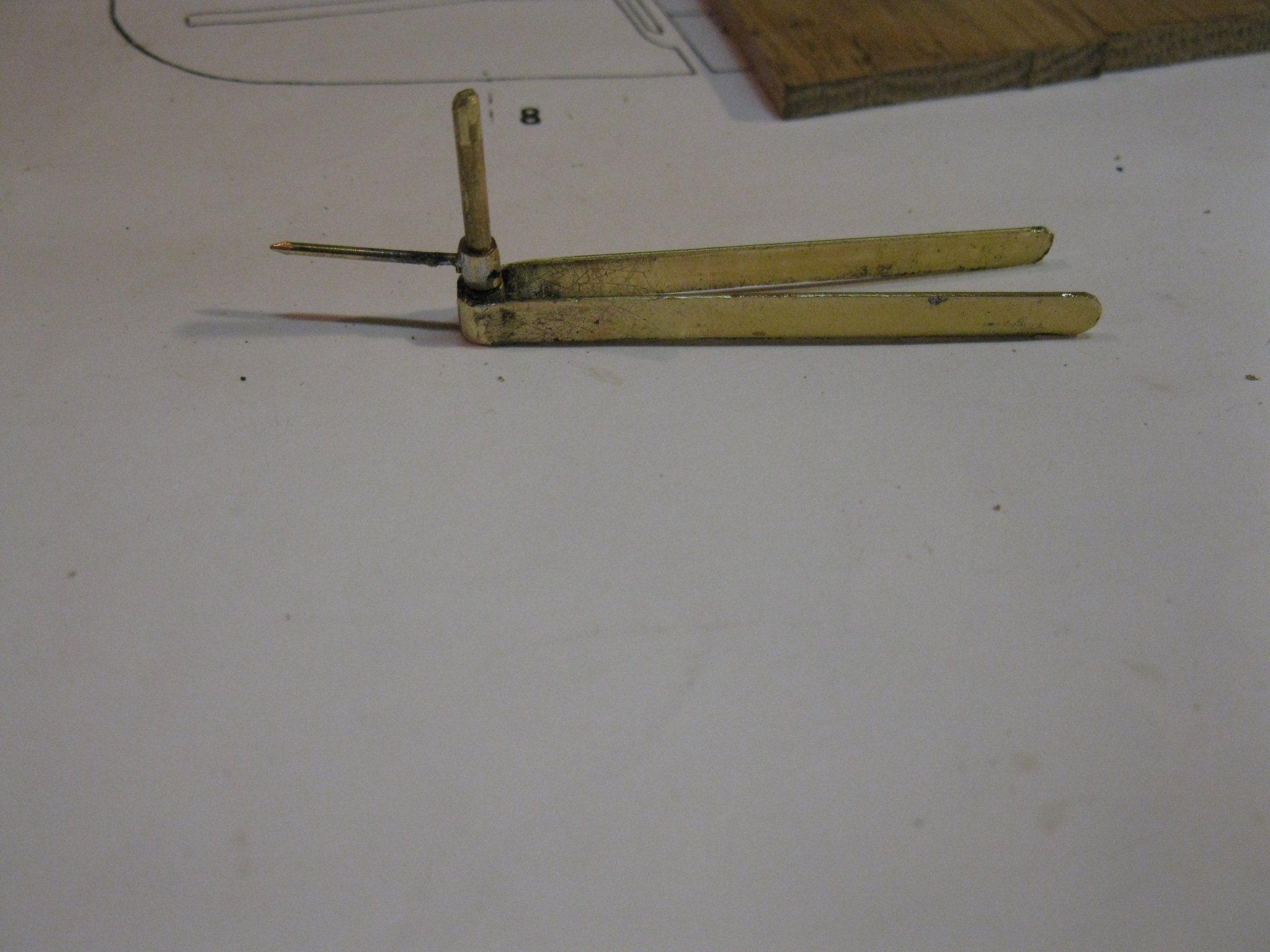
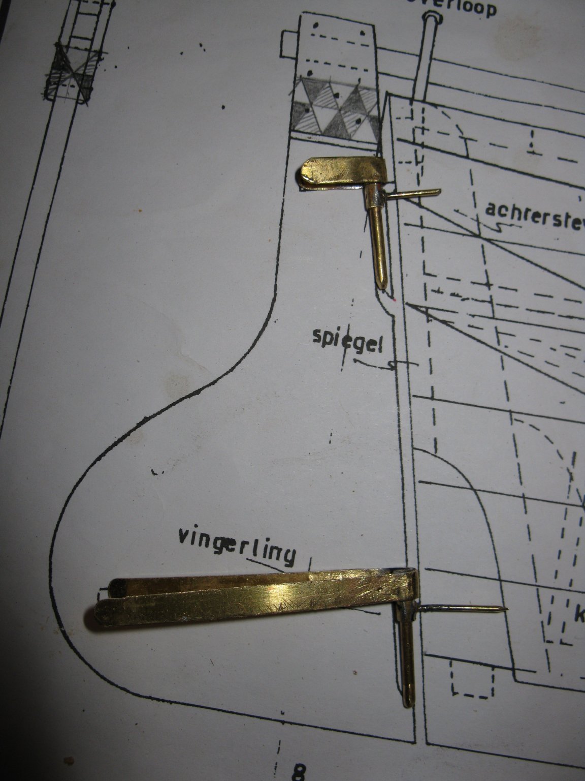
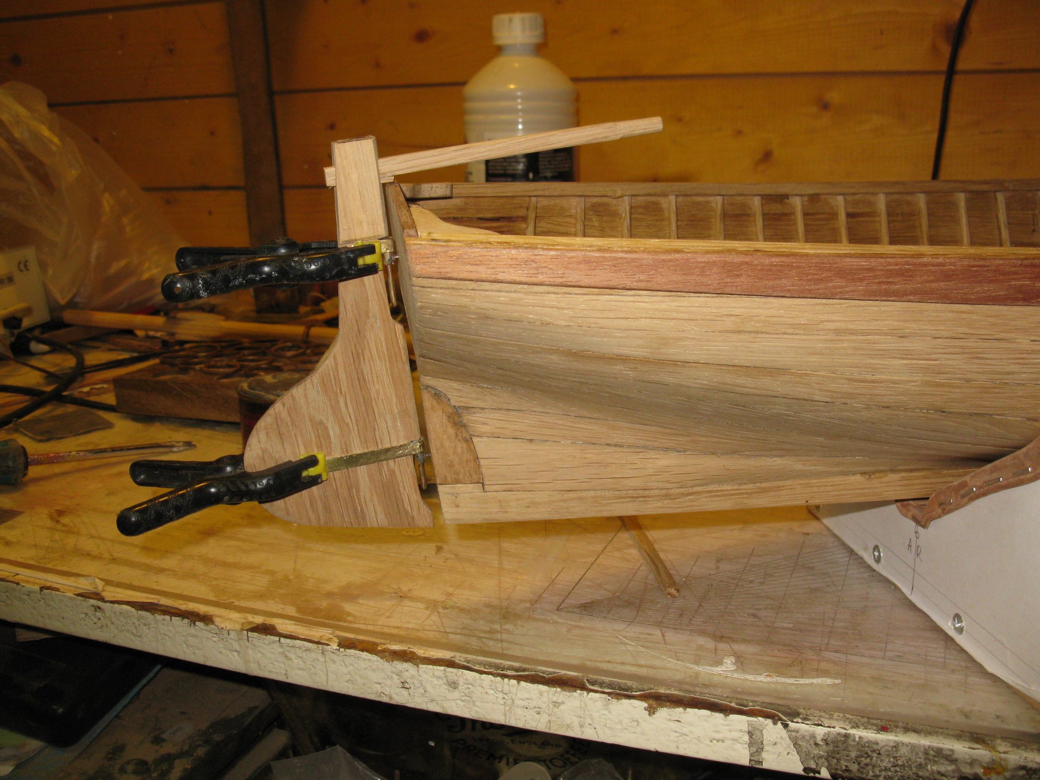
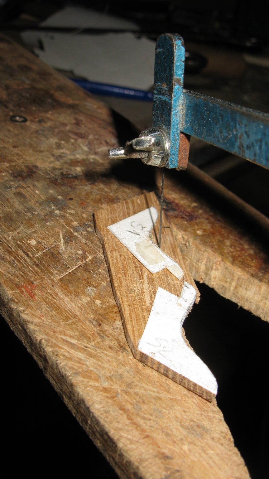
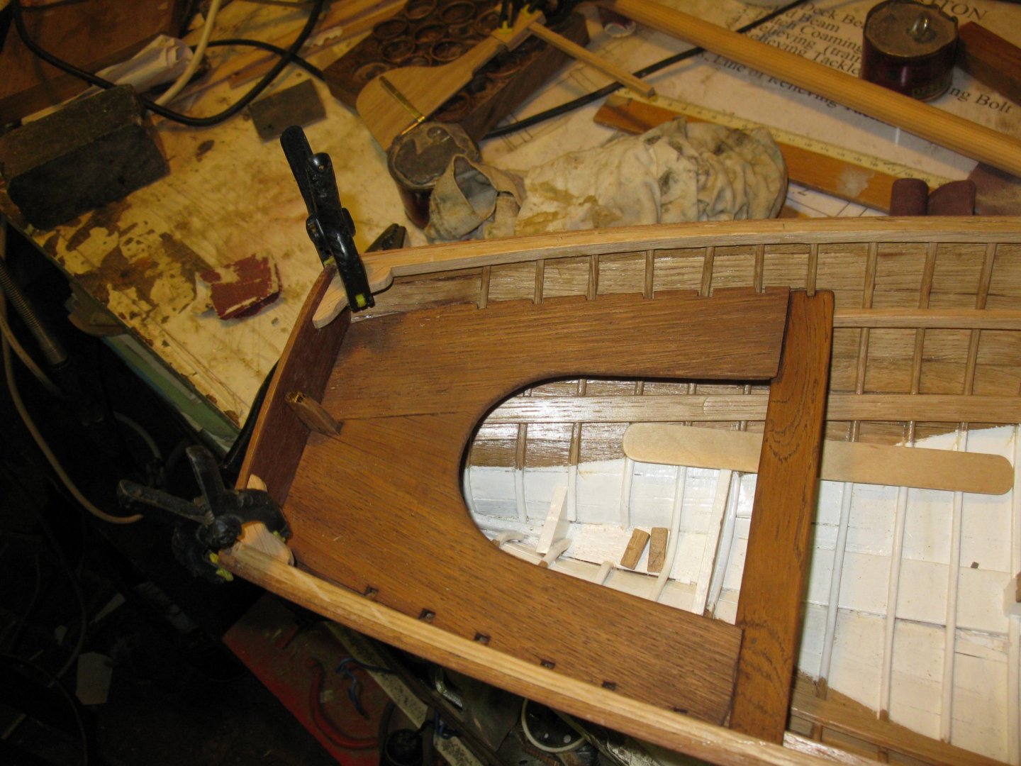
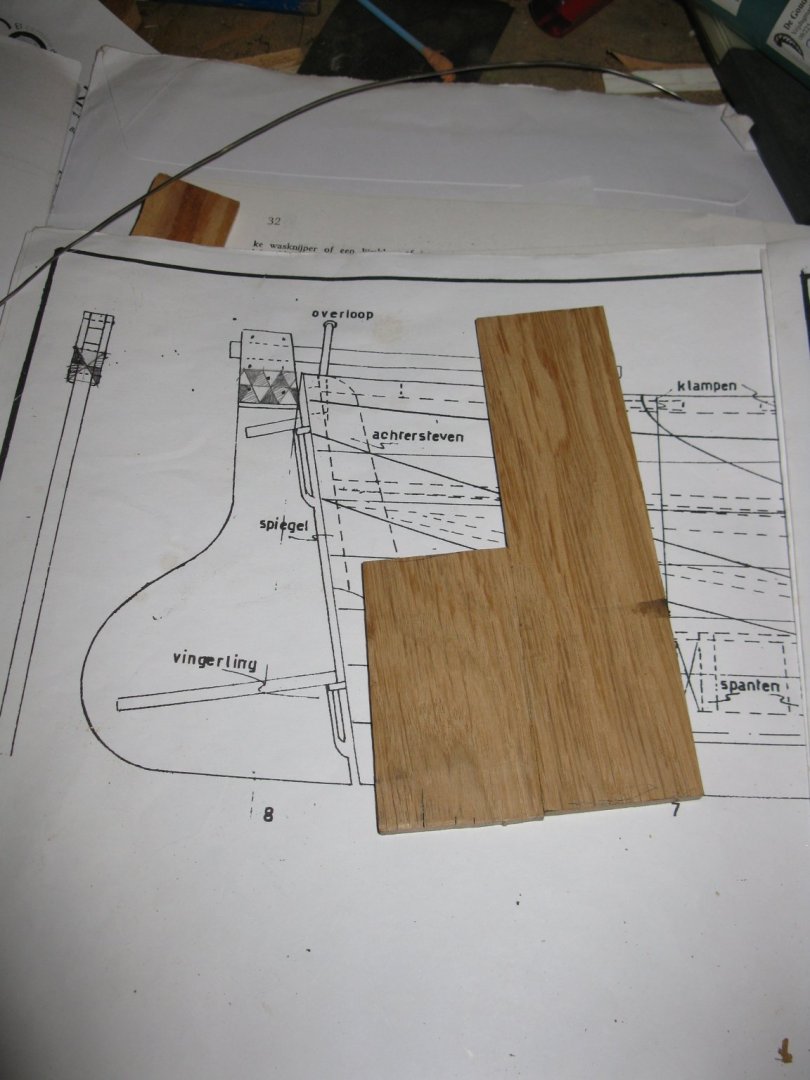
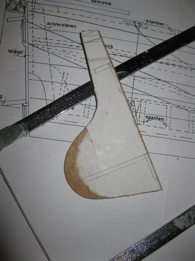
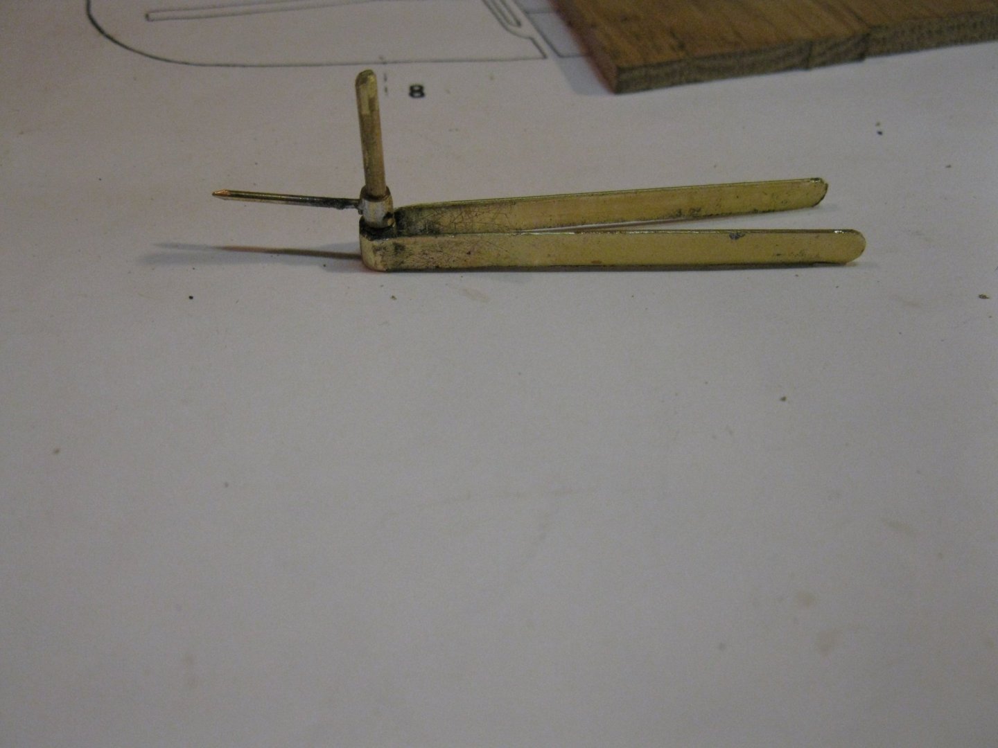
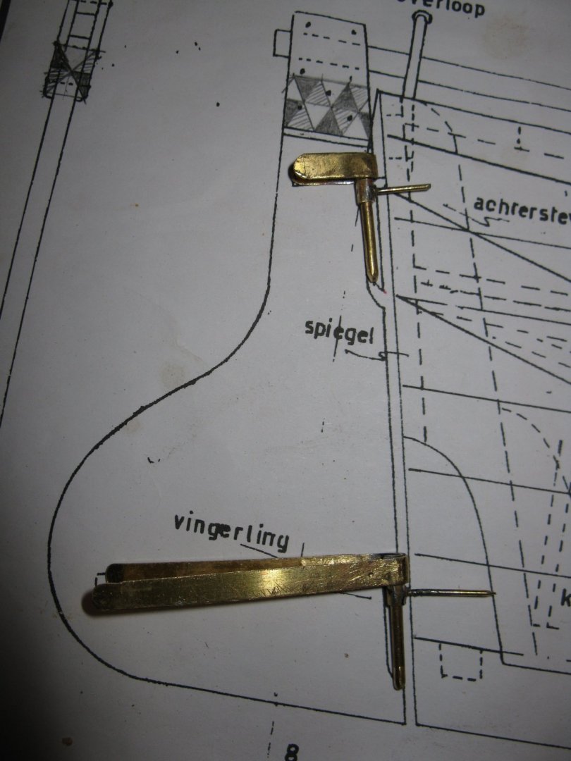
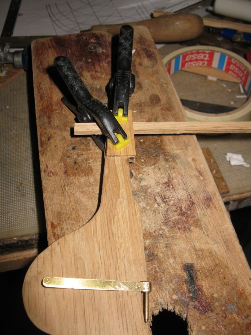
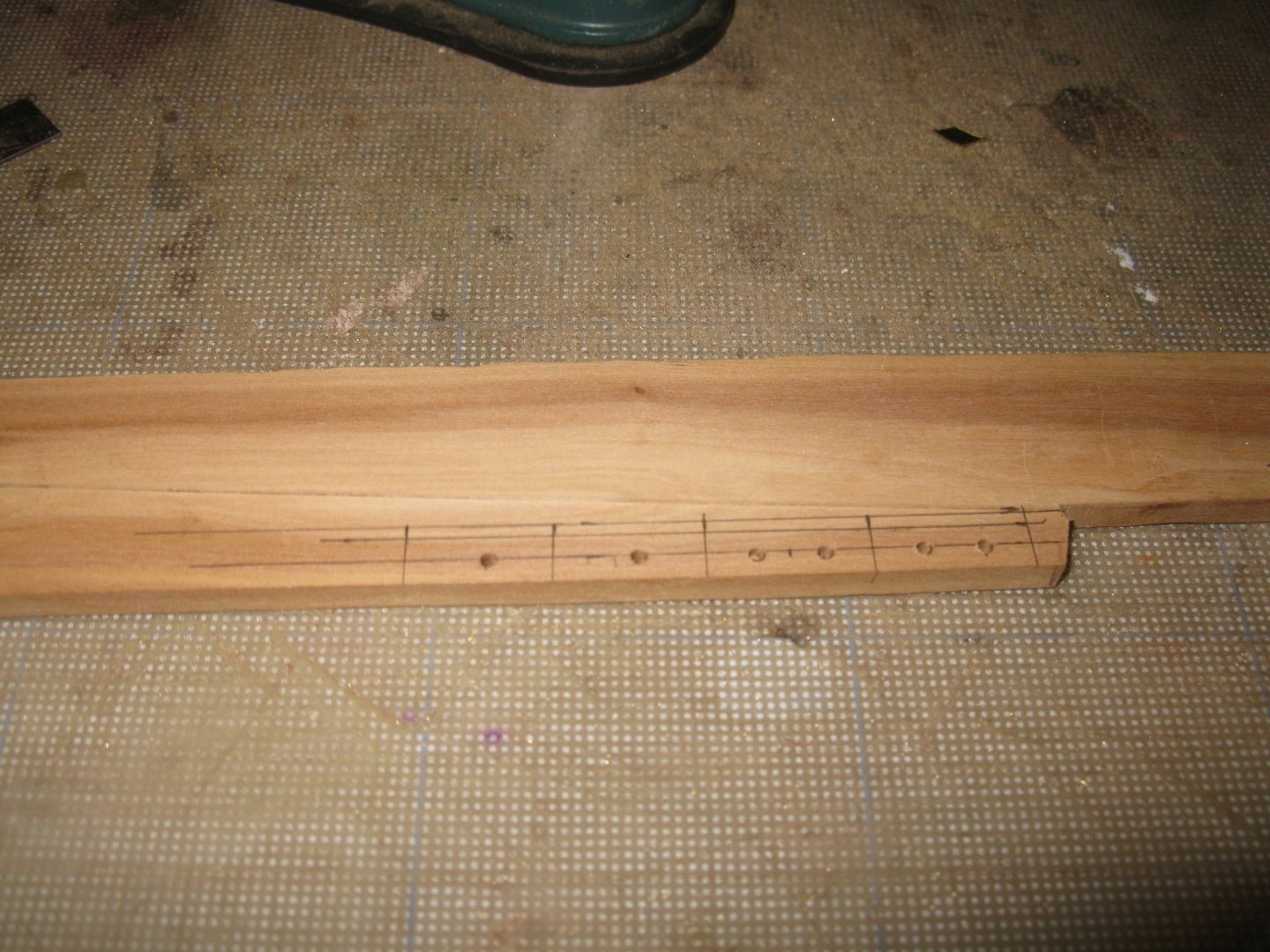
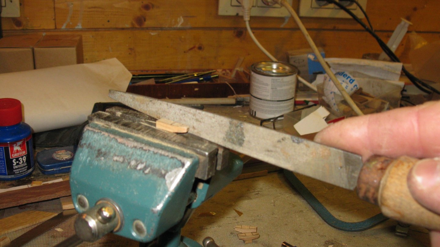
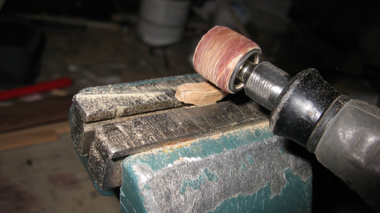
Part 9: The rudder. To make the rudder I glue two oak planks together. The rudder is sawn out and the round side is sanded to narrow it. Making pintles and braces. Making the rudder head and the tiller. Fitting the rudder on the model.


-
Thank you for the complement, Keith Thanks Moab, I vist this forum for 4 or 5 years and in this period I learned much more about ship modeling than I read in books during all the time before. I am very pleased that I can contribute and share my experiences.
-
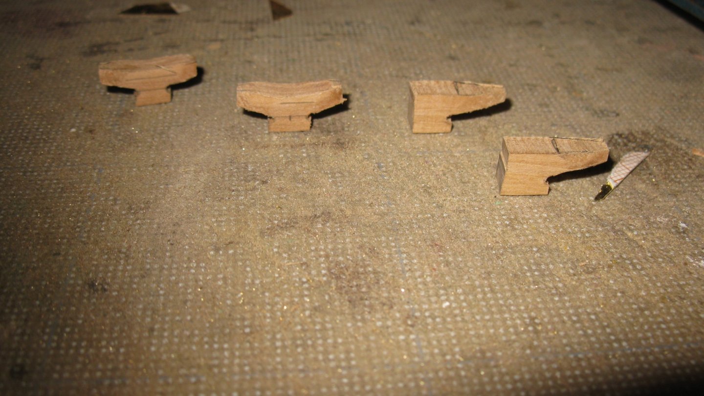
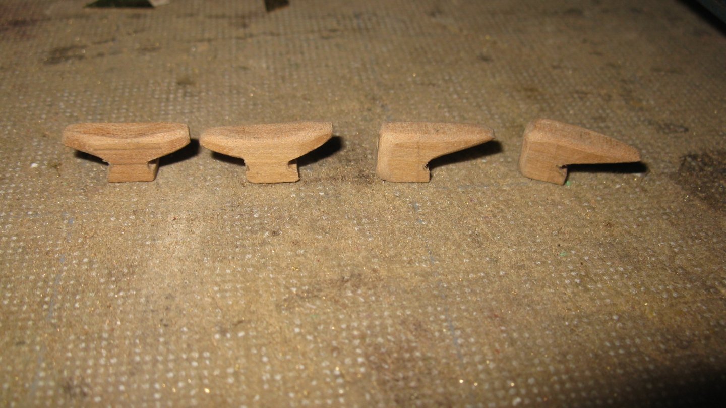
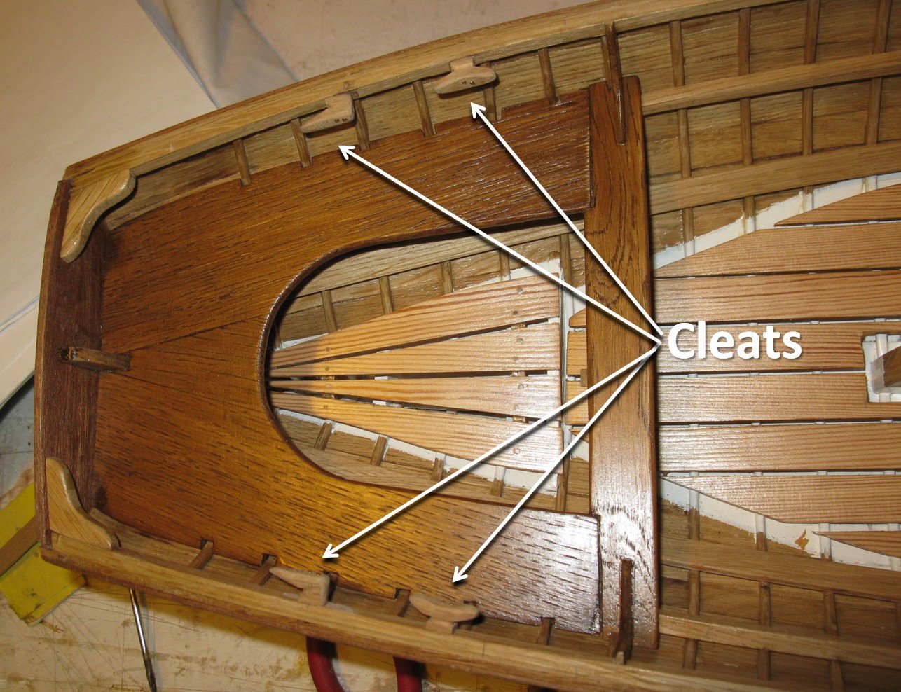
8.8: The cleats. Like on all sailboats some cleats have to be placed. I make them from fruit wood (I believe apple). I don't believe the making process needs a lot of explanation. The pictures show everything. The cleats around the helm area: Thank you to follow. Thank you for the likes. And thank you for the constructive comments. Till next week!

- 209 replies
-
- 13
-
-
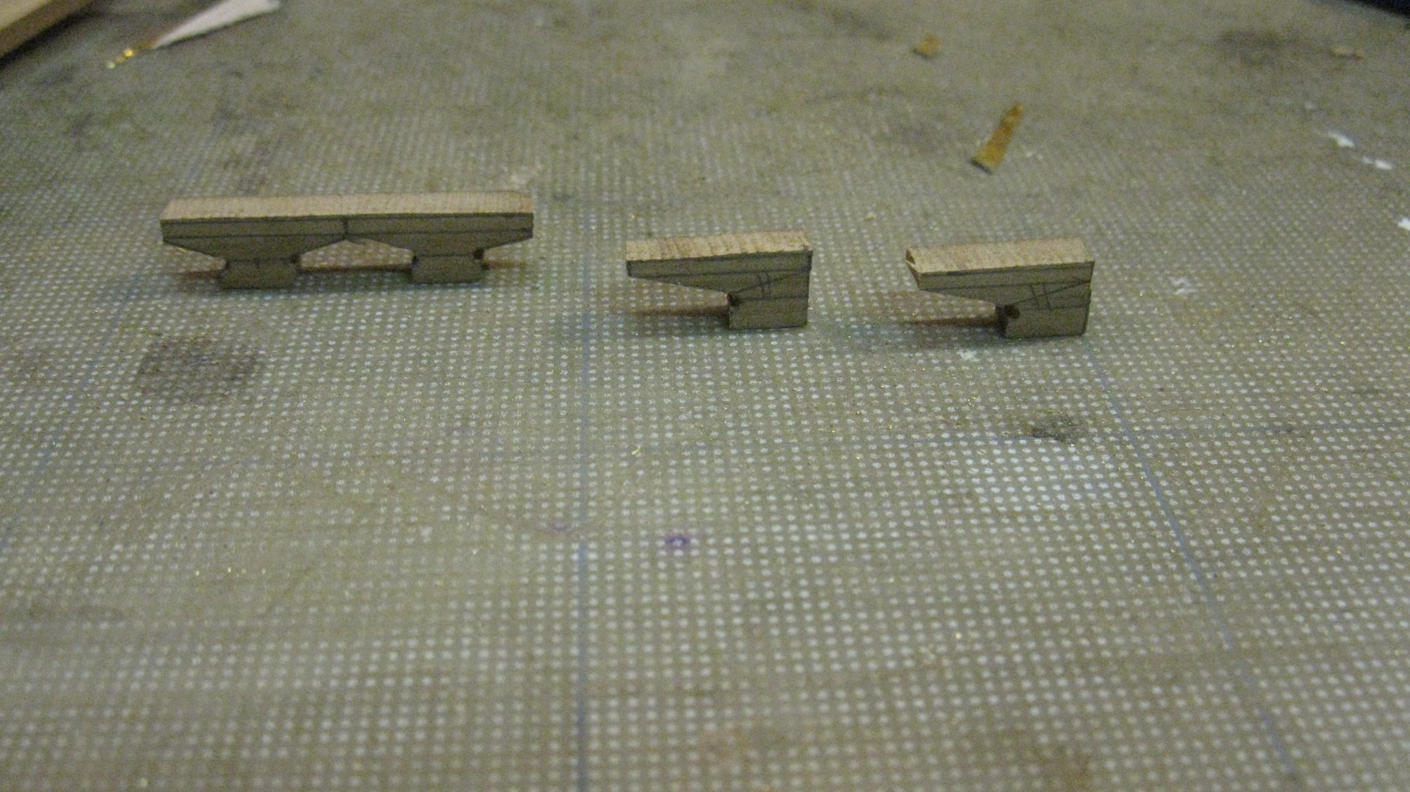
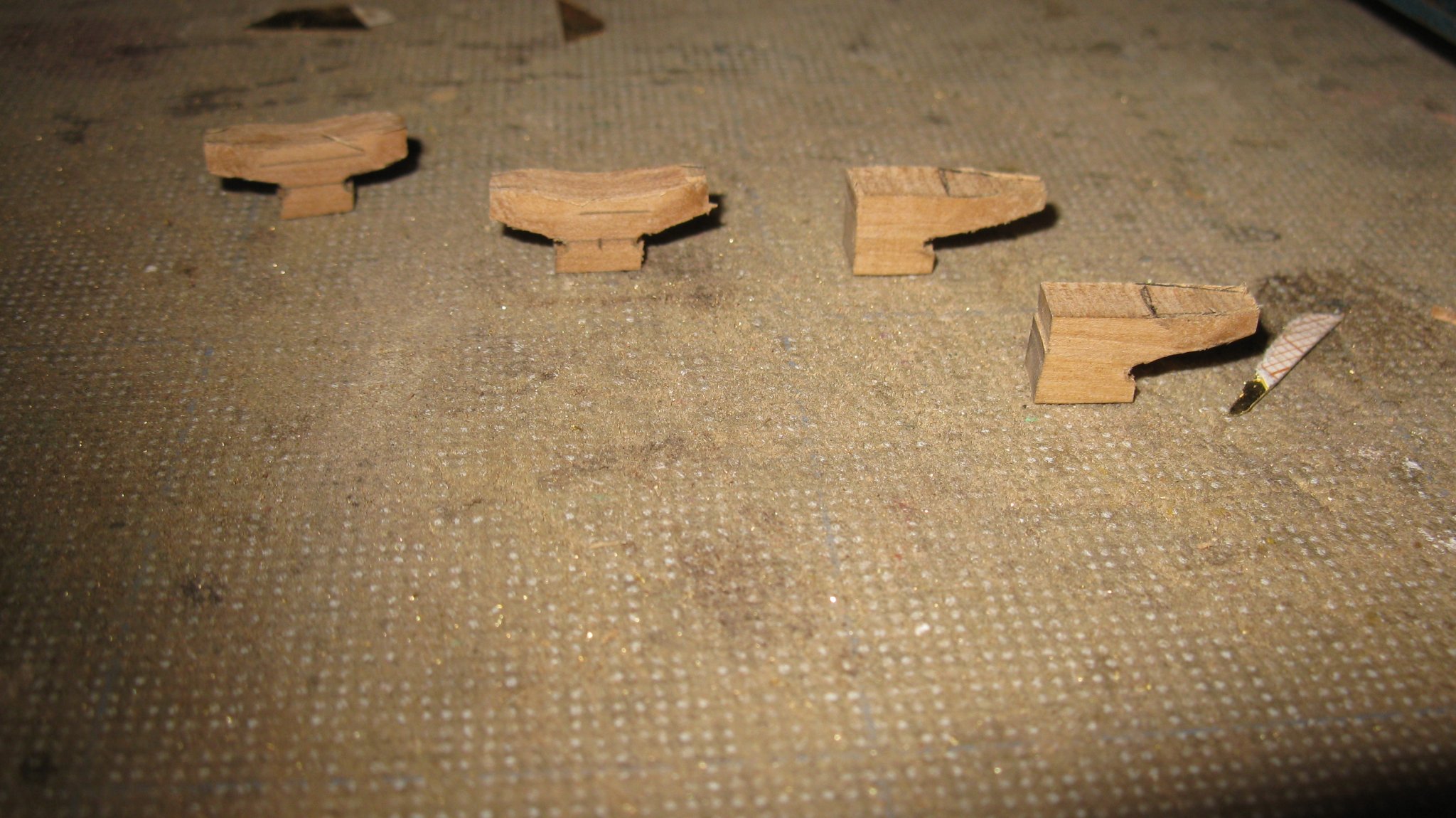
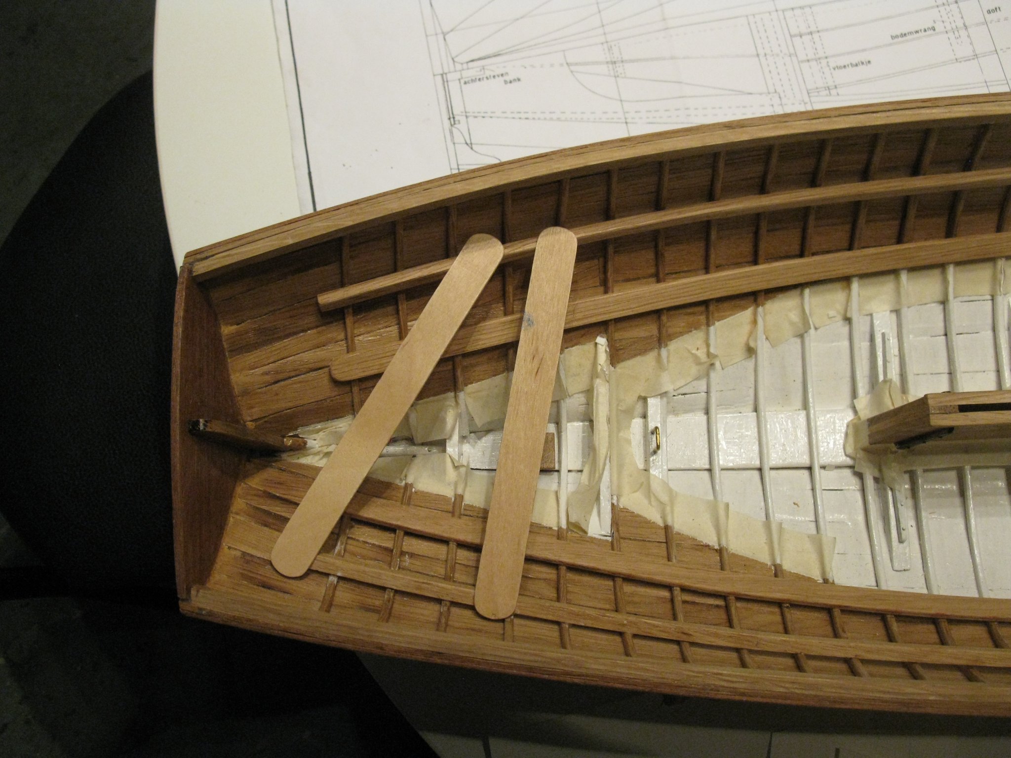
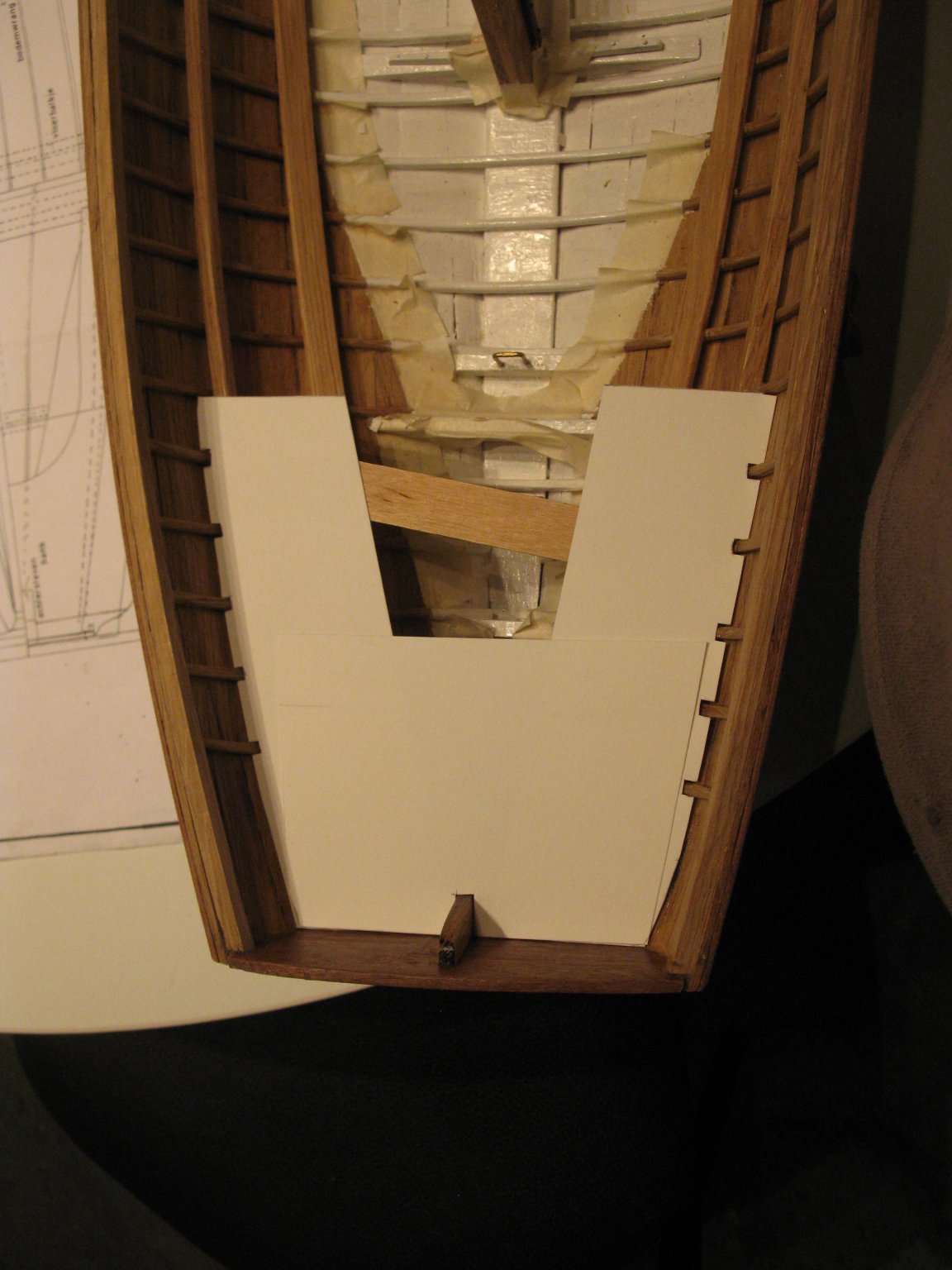
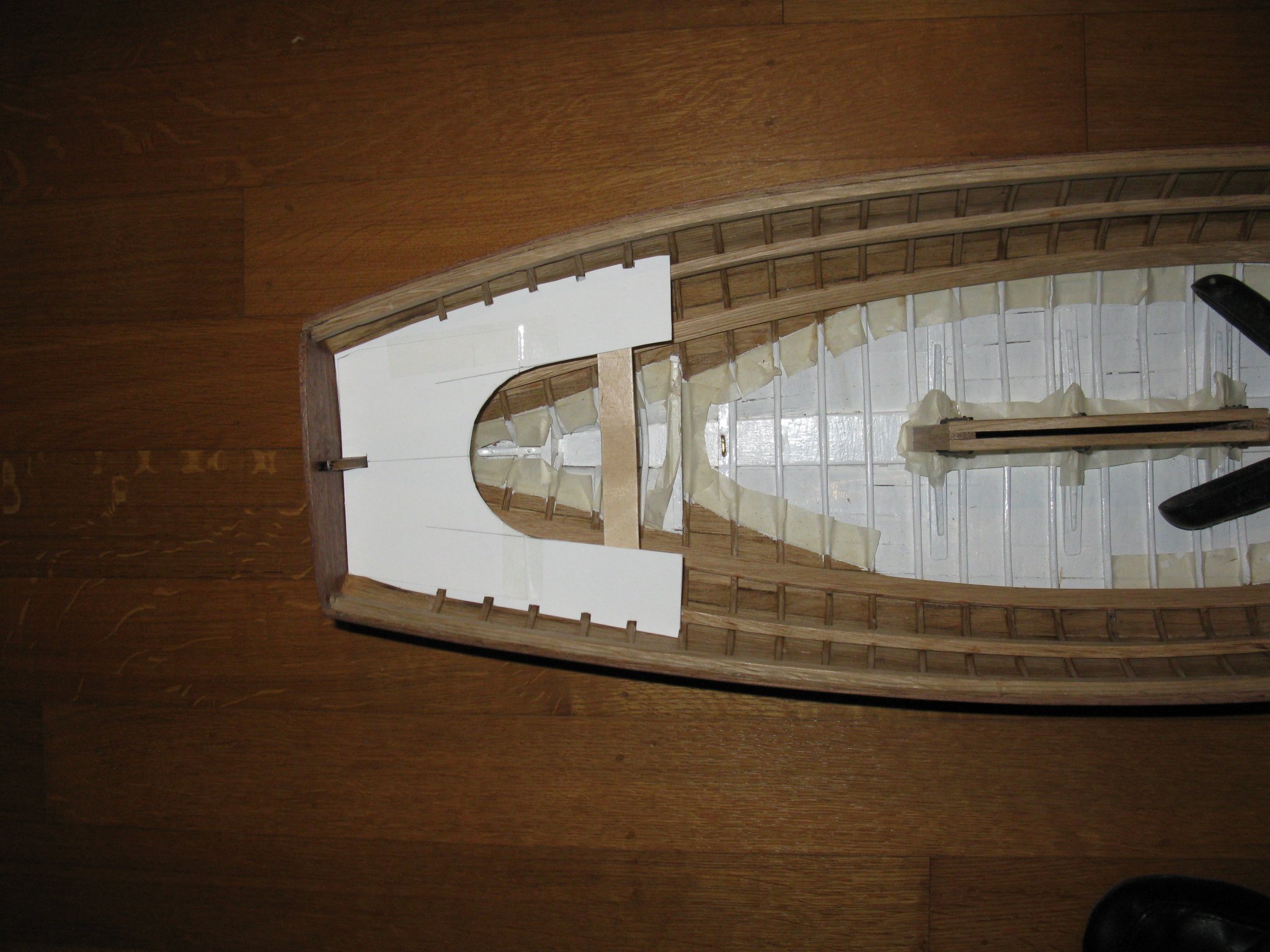
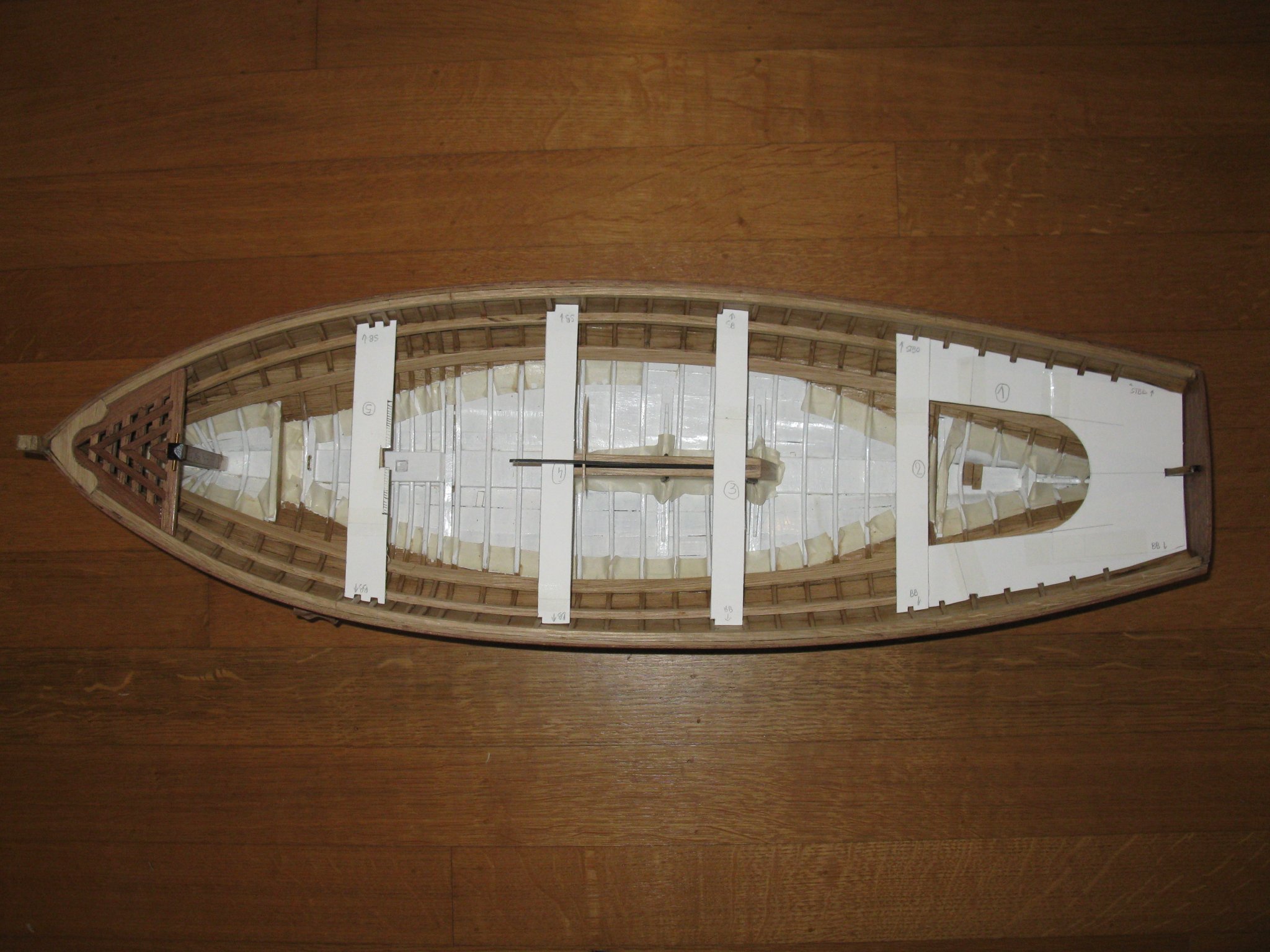
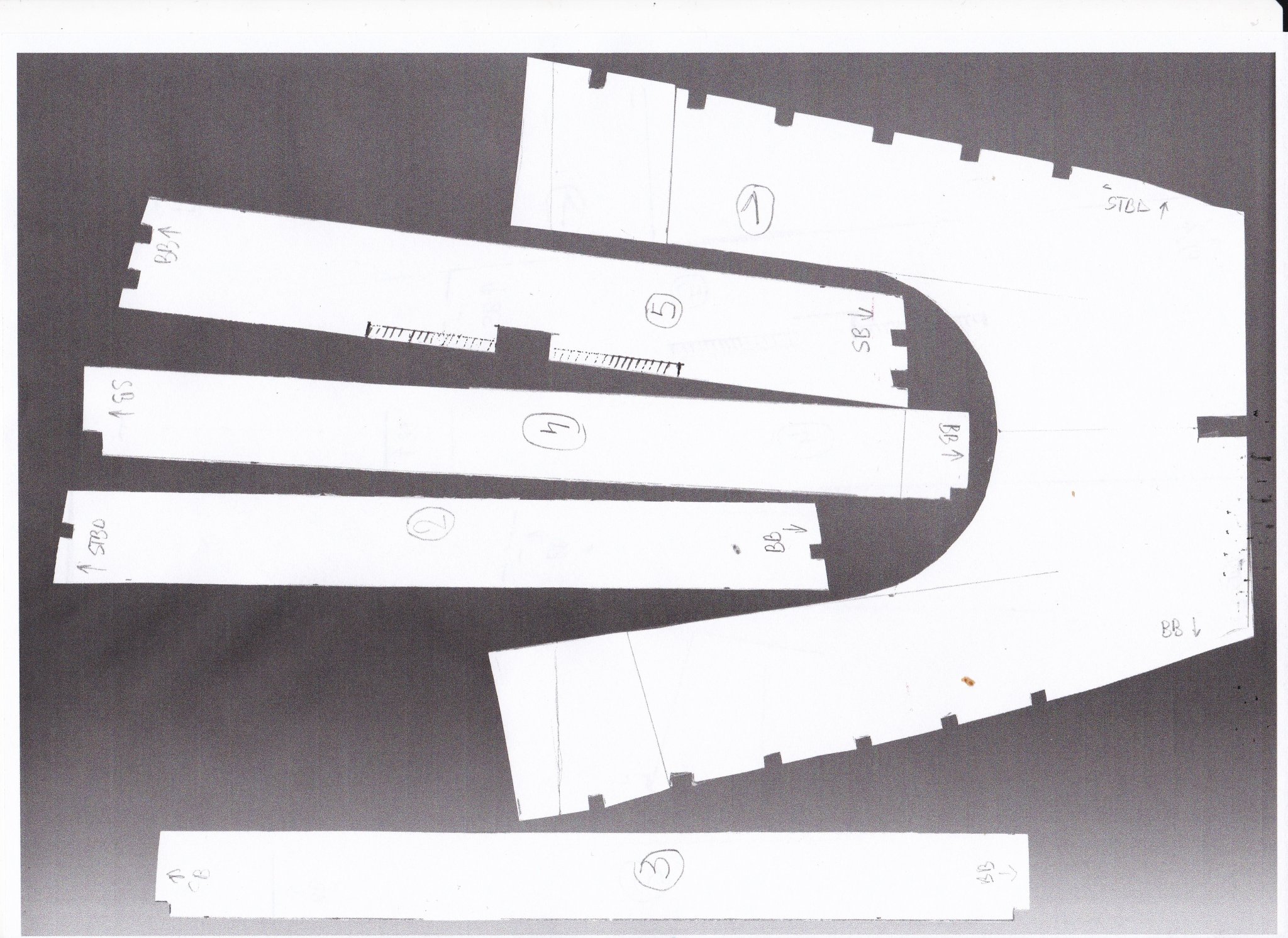
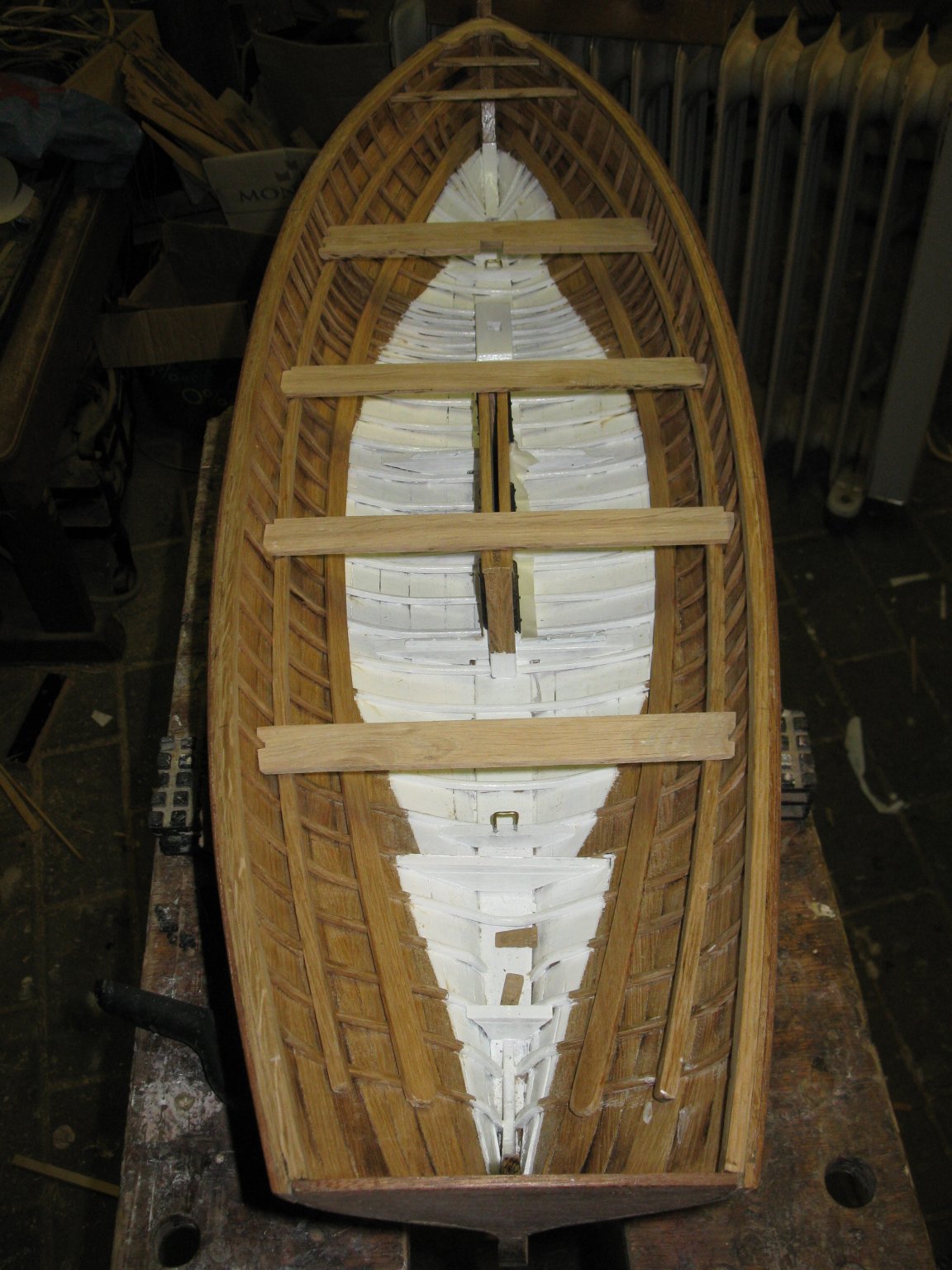
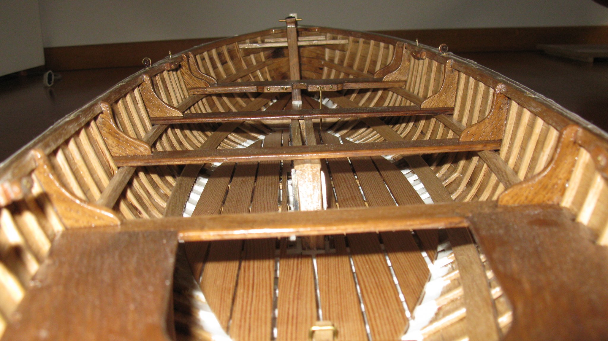
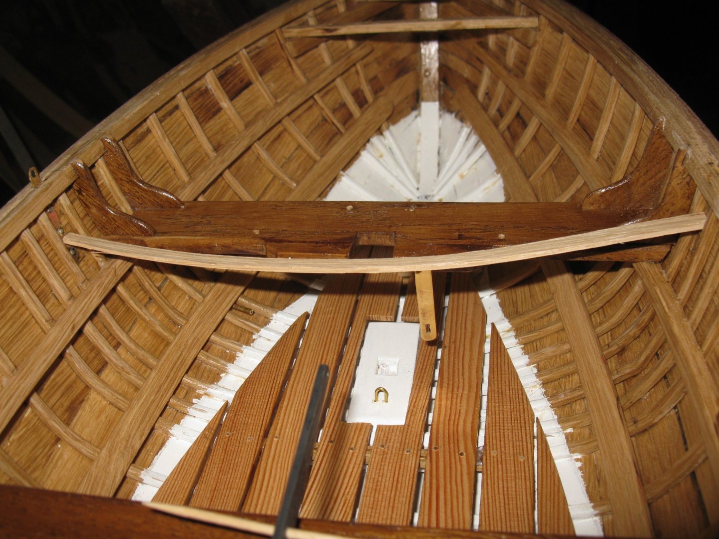
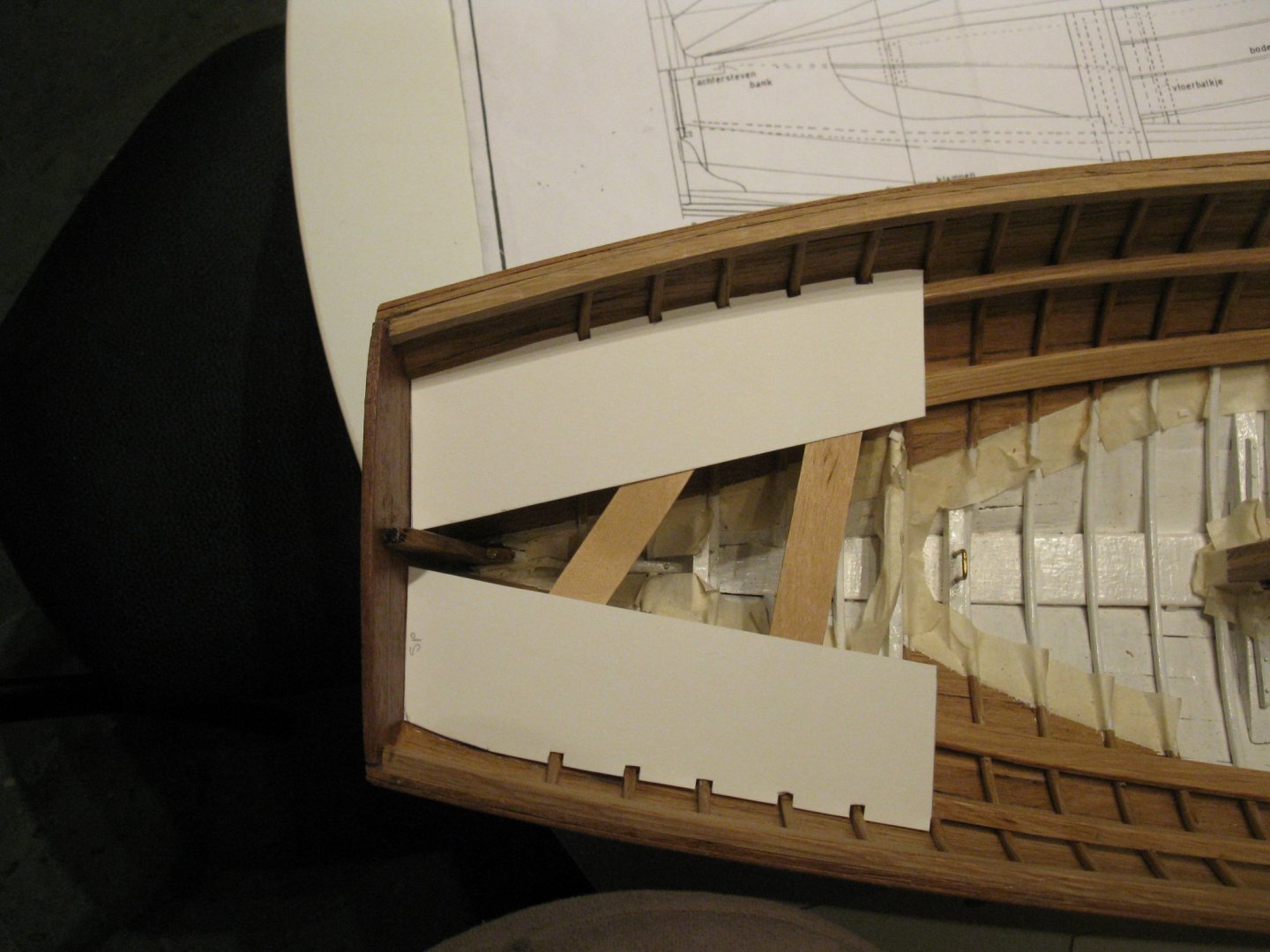
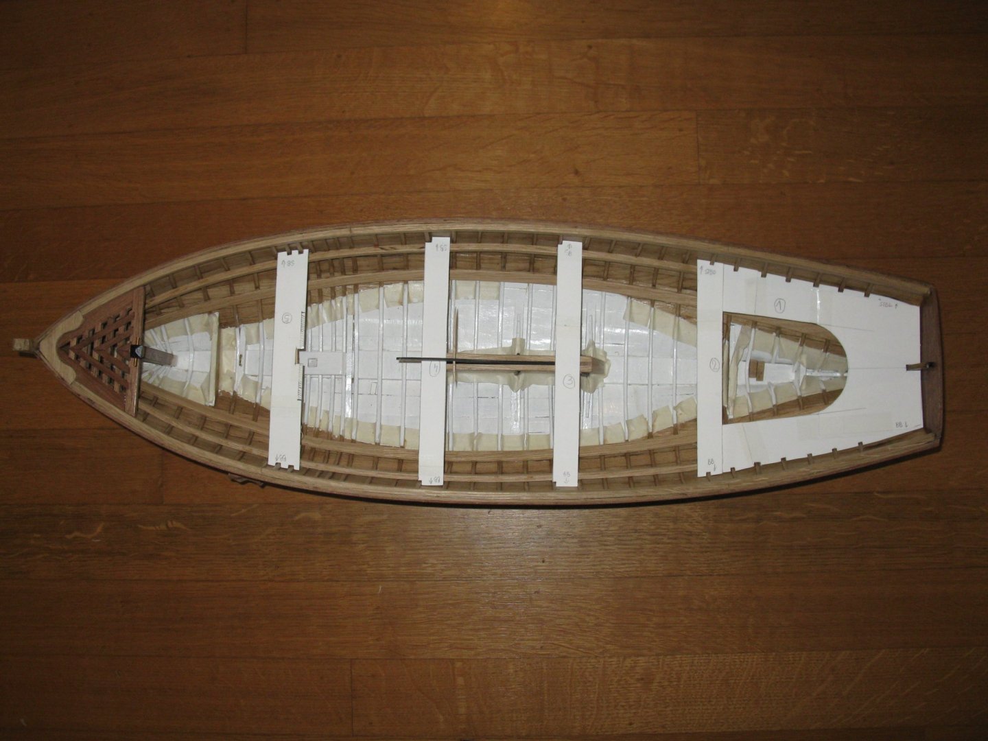
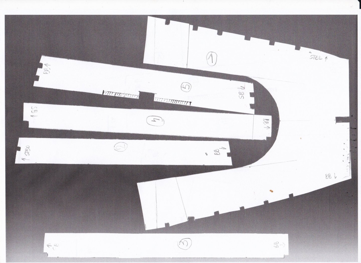
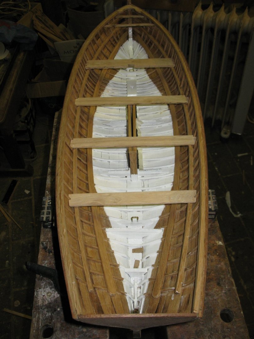
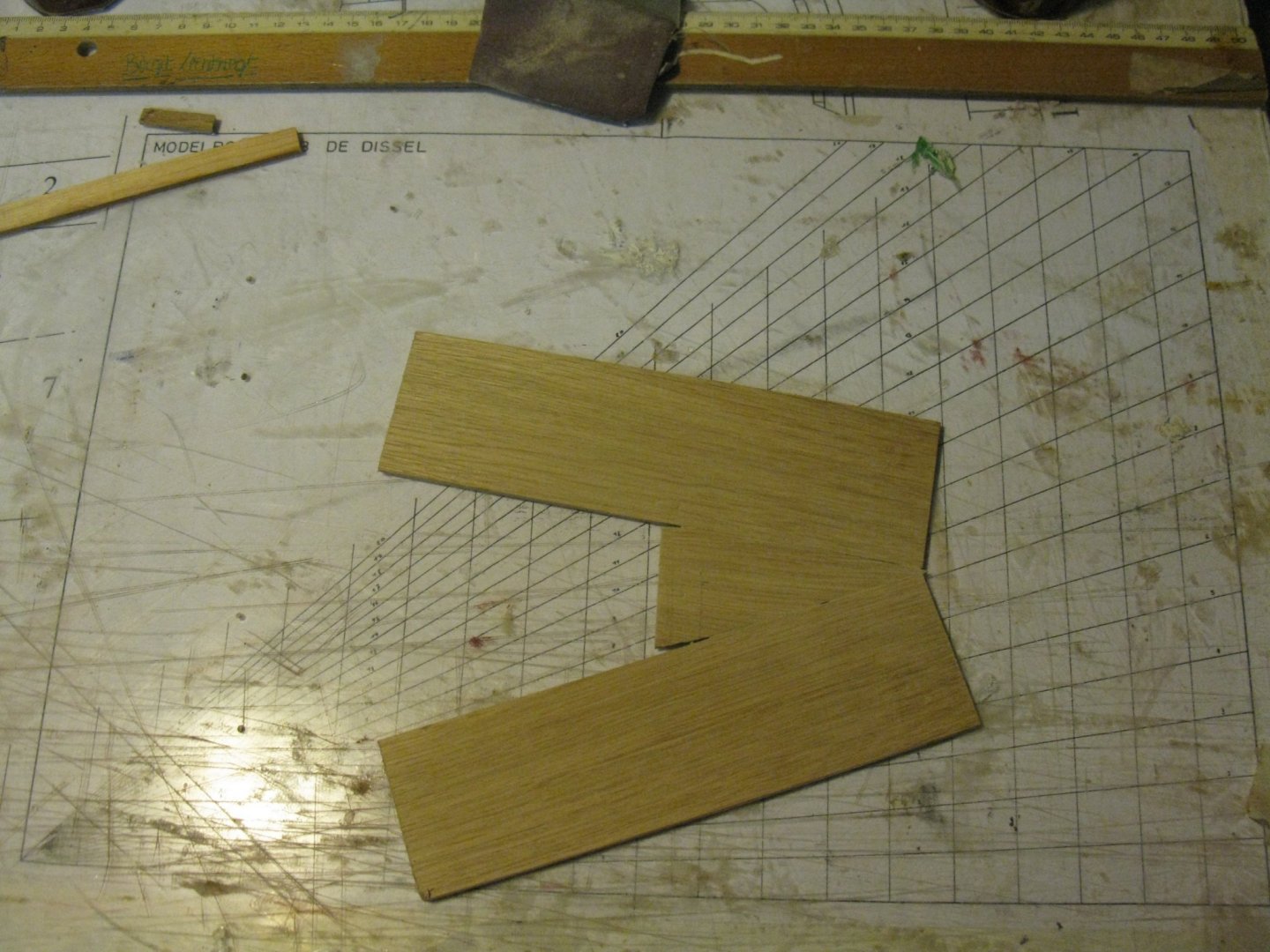
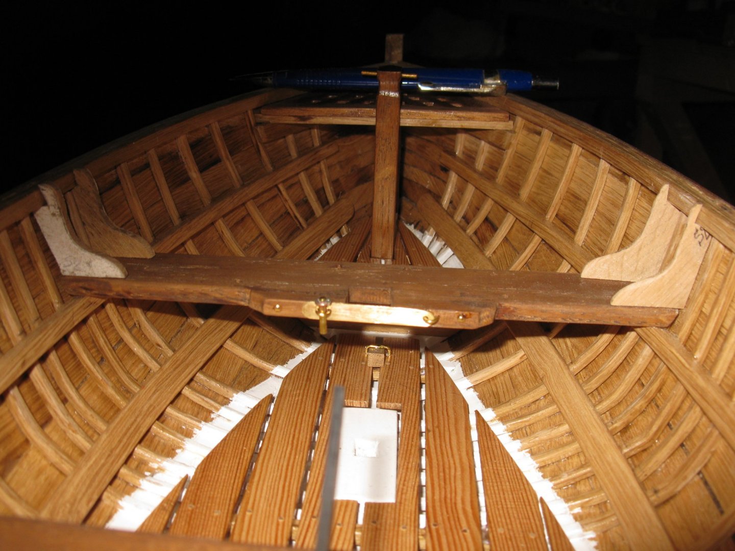
8.7 The thwarts To determine the shape of the aft thwart I lay some small shelves across both risers. Then I make periphery cards of both sides out of rigid drawing paper. And also one of the middle part. I tape the three cards carefully together without shifting them, draw the shape of the thwart and cut it out. My first template is ready. I make in the same way templates for the other thwarts. I make a photocopy of all my templates with the cover of the scanner up, lake that I have a nice contrast. The templates can now been glued on the wood and be sawn out. The three forward thwarts. The aft thwart is a little more complicate. For this one I start with gluing three pieces of 3mm oak together. The I glue the template on it and saw it out. The forward thwart serves also as mast support and pin rail. Overview of the thwarts. All thwarts are strengthened with vertical knees. The forward mast bench even has four. The make them I fit also first paper templates which I use to saw out the knees. The knees provisionally set on the forward thwart. All the knees are glued in place and varnished.


- 209 replies
-
- 12
-
-
Thank you Keith and John Thank you for the info on the masking tape, Patrick. Thanks Gary
-
Very impressive!
-
Such a neat metal work!
-
Patrick, Glad to see that the shipyard is in operation again!👍
- 756 replies
-
- 3
-
-
- galleon
- golden hind
- (and 2 more)
-
Really nice done! A pity that the oars of my gaff sail boat are already made.
-
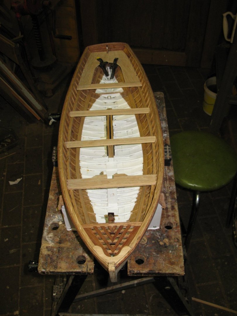
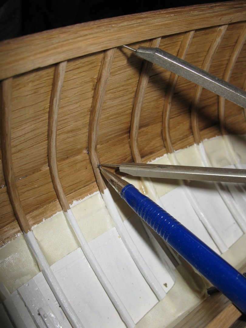
8.6 The risers The risers are long 5x5 mm oak bars. The upper side has to be as much as possible horizontal to give stable support to the thwarts. The frame to which the risers are to be glued are in different inclinations according to their position in the hull, so I shed one side diagonally at the ends and gradually less towards the middle. I do this a bit on the feeling, but the result is not so bad. Gluing the riser into position. When placing the starboard riser. I check if the height of the risers are equal to that of the center board where the thwarts will come. Thank you to follow. Thank you for the likes. And thank you for the constructive comments. Till next week!

- 209 replies
-
- 12
-
-
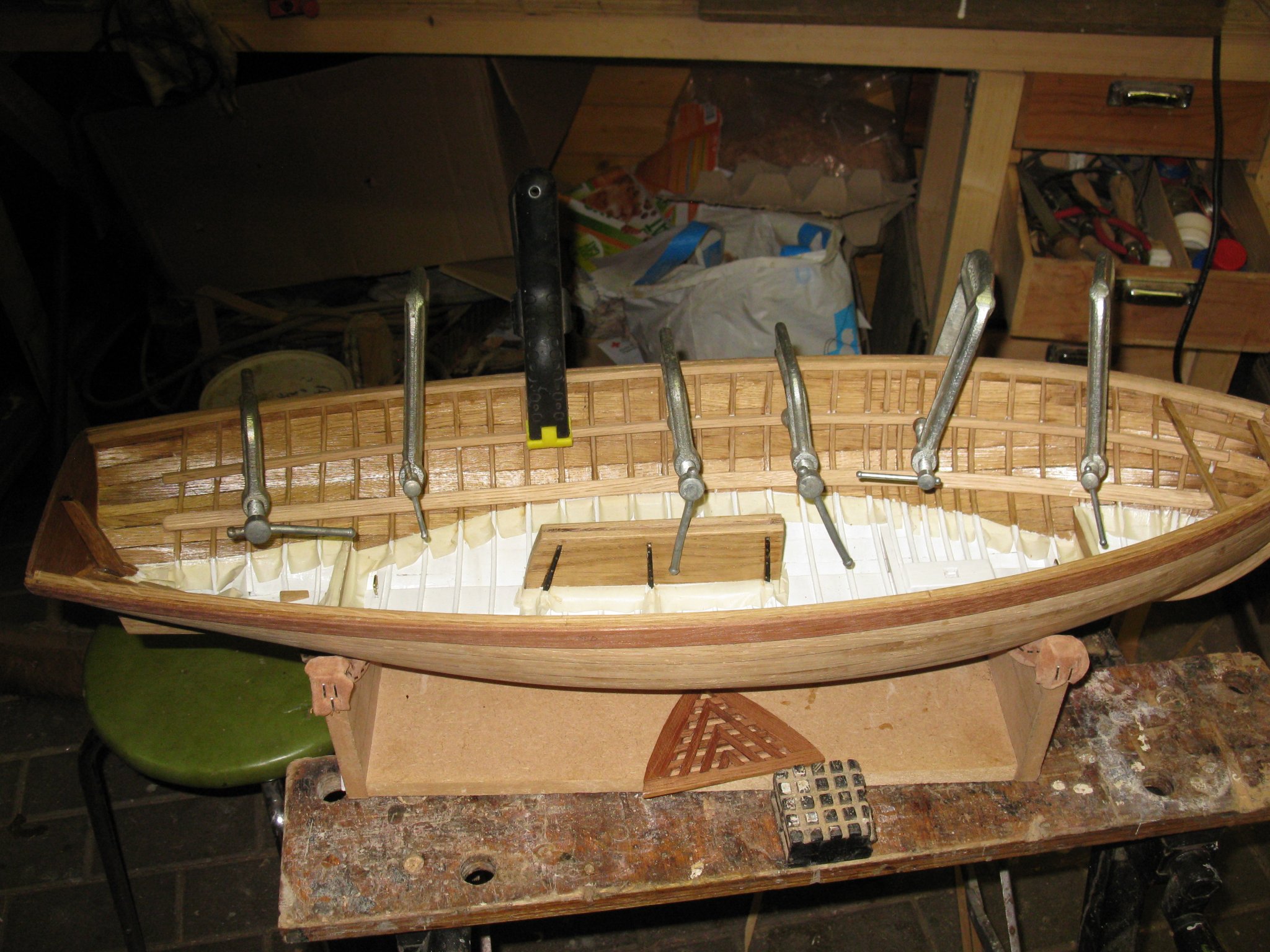
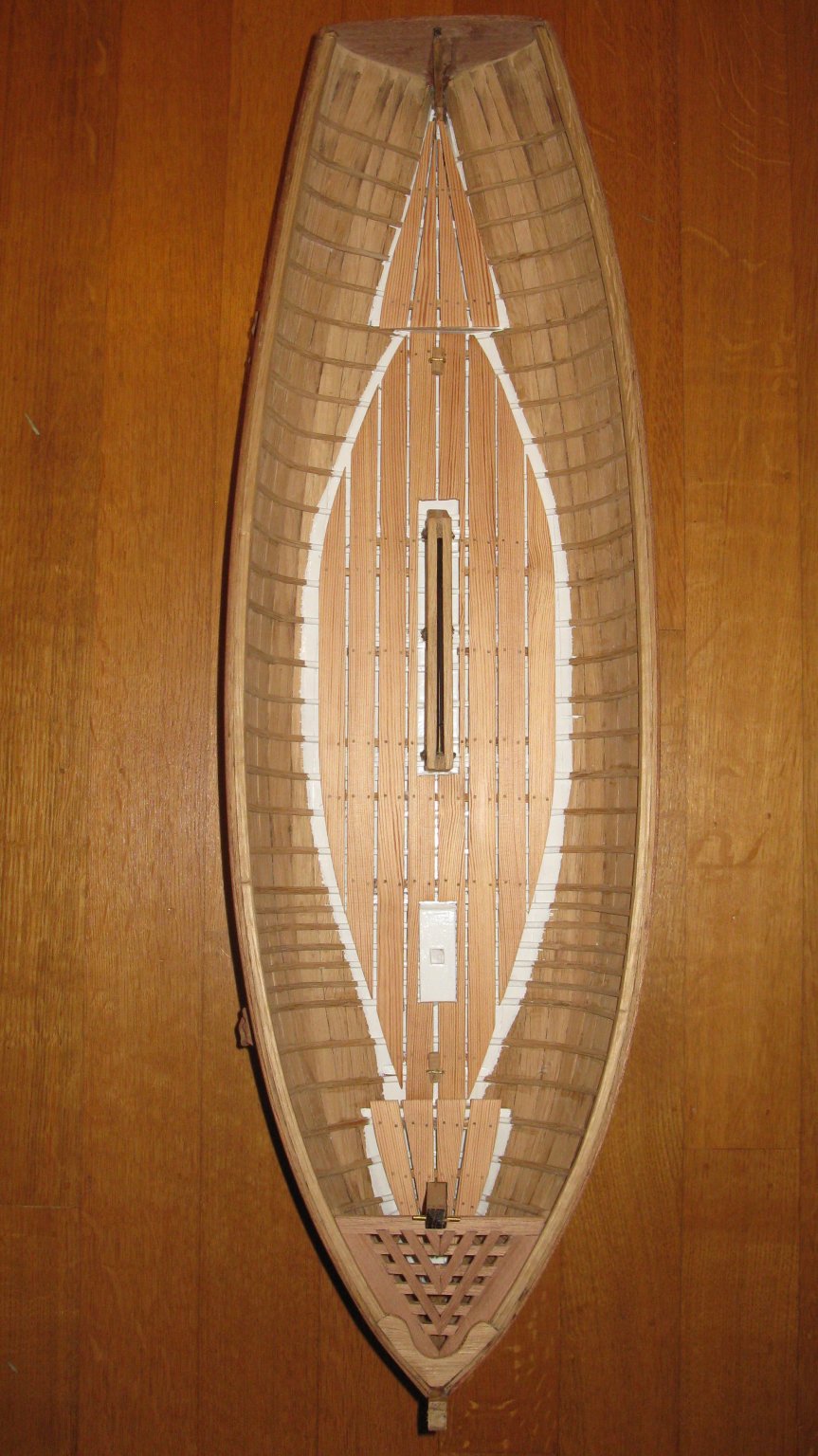
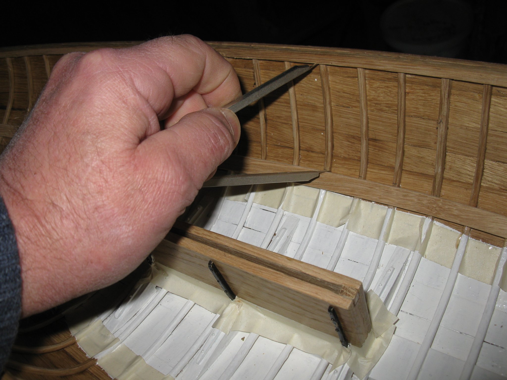
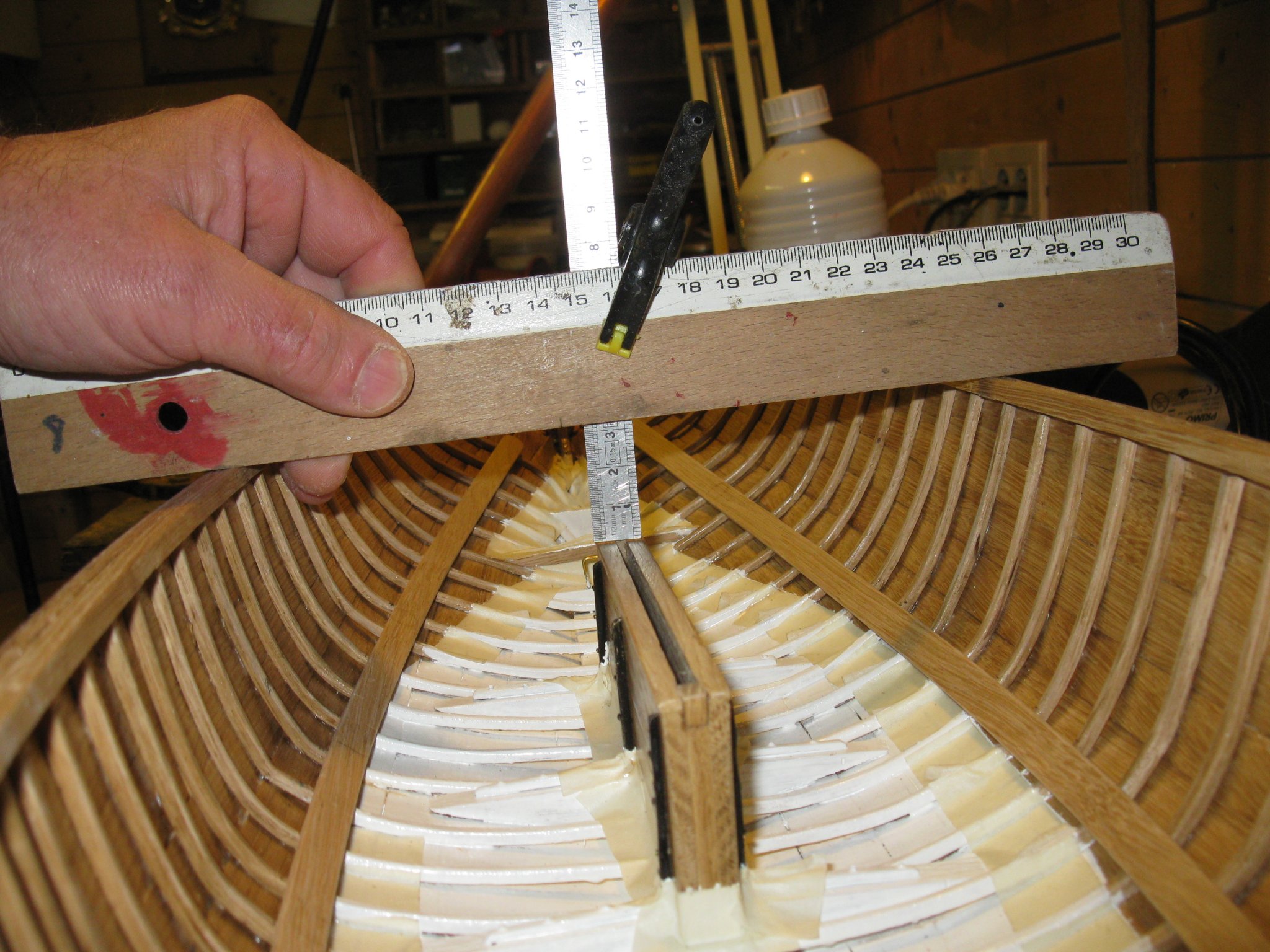
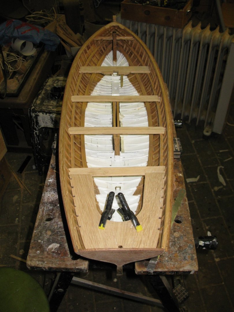
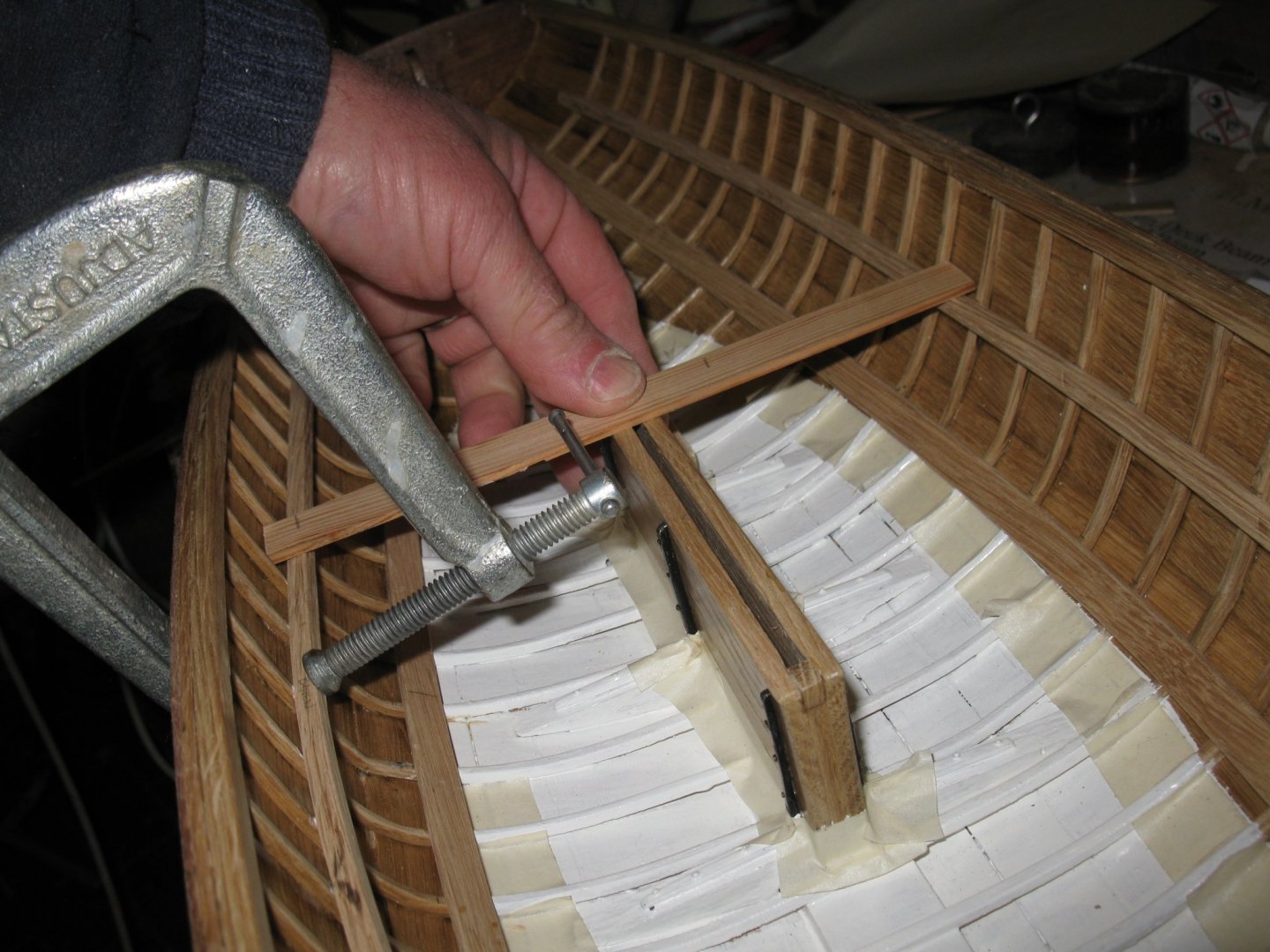
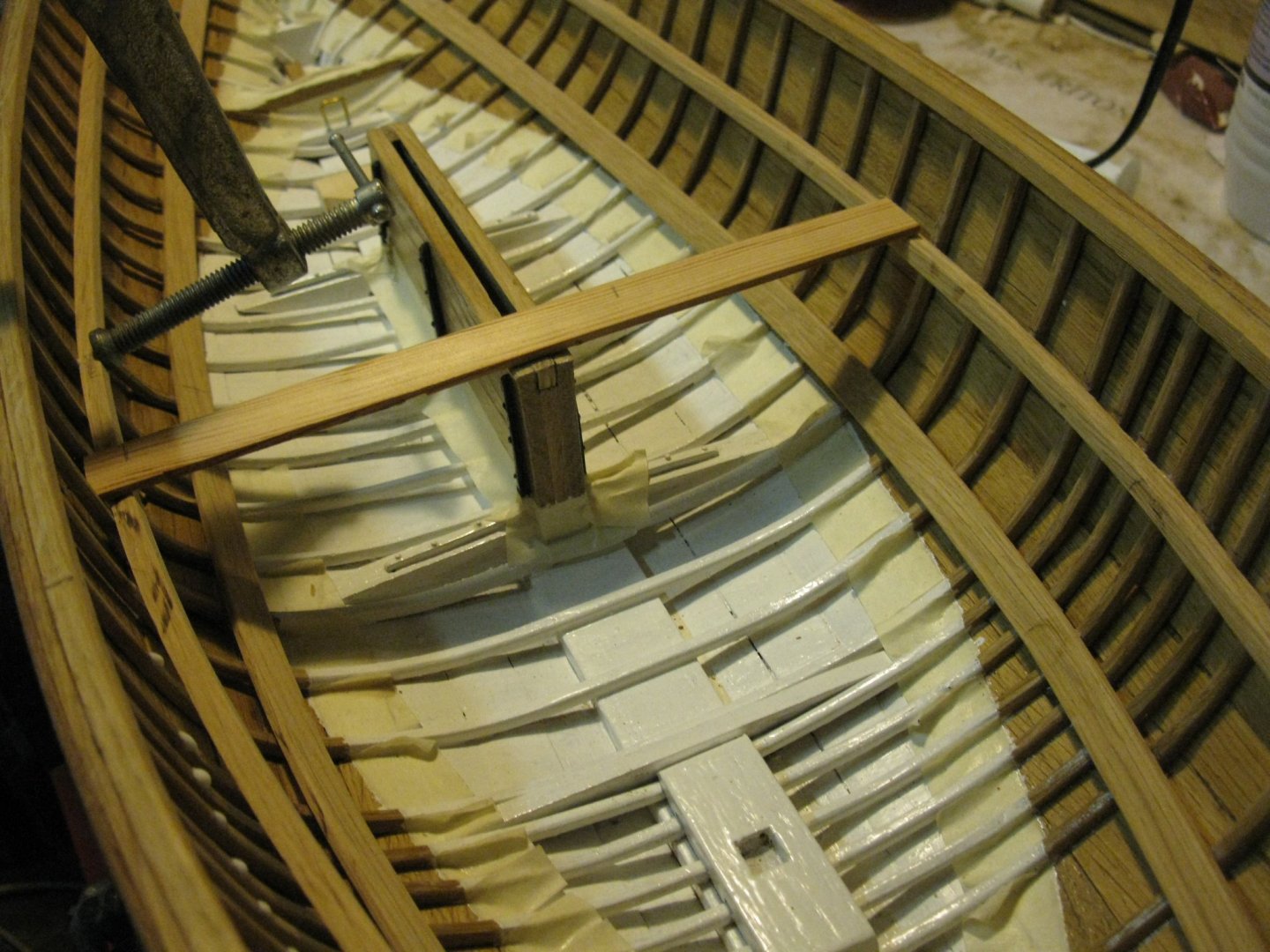
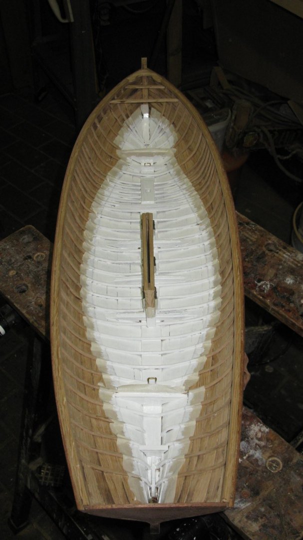
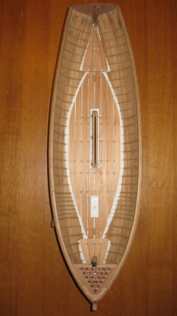
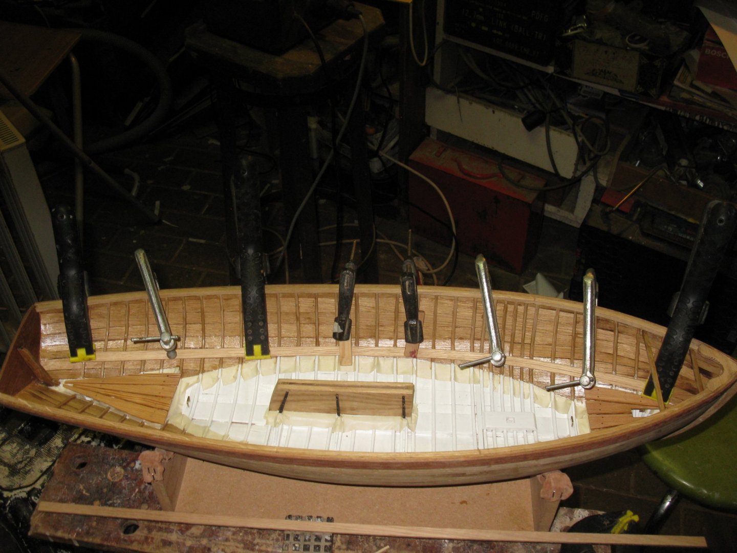
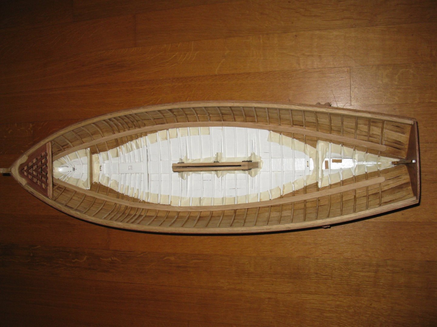
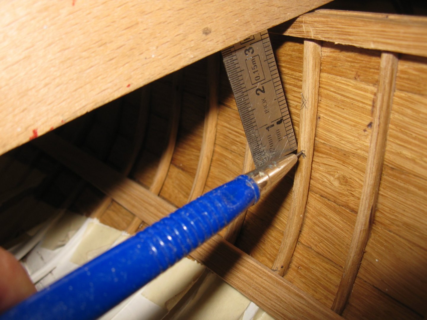
Before continuing the inside of the hull, I will paint the bottom. The application of masking tape is more time consuming than the painting itself. It needs three coats of paint to be opaque. When I remove the tape the edges are not as clear-cut as I hoped. Fortunately, when the bottom boards are in place it is not that striking. Now I will varnish the sides above the bottom bards, anon when the risers are placed the surface of the sides will not be so accessible anymore. The masking taping has to restart now on the other side of the line. Because some stringers and risers have to be glued on the frames, I varnish now only between the frames. Later I will do the frames together with the stringers and raisers. When the varnish is dry I glue the port stringer. To make sure that both stringers are at the same height I measure the height of the top of the port stringer in some spots ... ... and bring it over to the starboard side. Both stringers into place. The heights of the risers is even more important those that of the stringers because they will bear the thwarts. Two of the thwarts will rest also on the centre board case. Measuring the distance between the centre board case and the gunwale ... ...and bringing it over the according frames.


-
Imazing work Geatan. I finally understand what that little blue man is doing. He has been lost all this time in the maze of compartments and beams below deck and is desperate looking for the exit.
-
Gary, I agree with all previous comments. The hull looks remarkably clean compared to the deck and the superstructure. Will you age it as well?
-
HMS Pickle by mtbediz - FINISHED - 1:40
G.L. replied to mtbediz's topic in - Build logs for subjects built 1751 - 1800
Mustafa, your companion and skylight are looking great. -
Thank you Vaddoc, Yes, considering the poor quality of the planking, I will paint the outside of the hull (cream color above the waterline, bordeaux color below). The rub rails and transom will be varnished as well as the inside of the boat. Thanks Bedford, An other difference is that you make a model of a real existing boat, mine is an imaginary vessel. Thank you Andy, I will start with the outfitting story next week. Thank you Mark Thanks Ab, I guess you have known the spiritual father of this gaff sail boat, Mr. Jules Van Beylen?