


G.L.
-
Posts
1,553 -
Joined
-
Last visited
Content Type
Profiles
Forums
Gallery
Events
Posts posted by G.L.
-
-
Mustafa, your companion and skylight are looking great.
- Old Collingwood, mtaylor and mtbediz
-
 3
3
-
23 hours ago, vaddoc said:
Beautiful! Will you paint the hull Geert?
Thank you Vaddoc,
Yes, considering the poor quality of the planking, I will paint the outside of the hull (cream color above the waterline, bordeaux color below). The rub rails and transom will be varnished as well as the inside of the boat.
23 hours ago, Bedford said:There's some very nice work going on there and I'm really enjoying the difference between your traditional type of boat and my modern glued lapstrake design.
Thanks Bedford,
An other difference is that you make a model of a real existing boat, mine is an imaginary vessel.
20 hours ago, AndyG said:This is really lovely! And she'll come even more alive as you start fitting her out, internally.
Andy
Thank you Andy,
I will start with the outfitting story next week.
2 hours ago, mtaylor said:I've been following quietly, G.L. Beautiful work and I'm also picking some tips.
Thank you Mark
2 hours ago, Ab Hoving said:An inspiring build!
Thanks Ab, I guess you have known the spiritual father of this gaff sail boat, Mr. Jules Van Beylen?
-
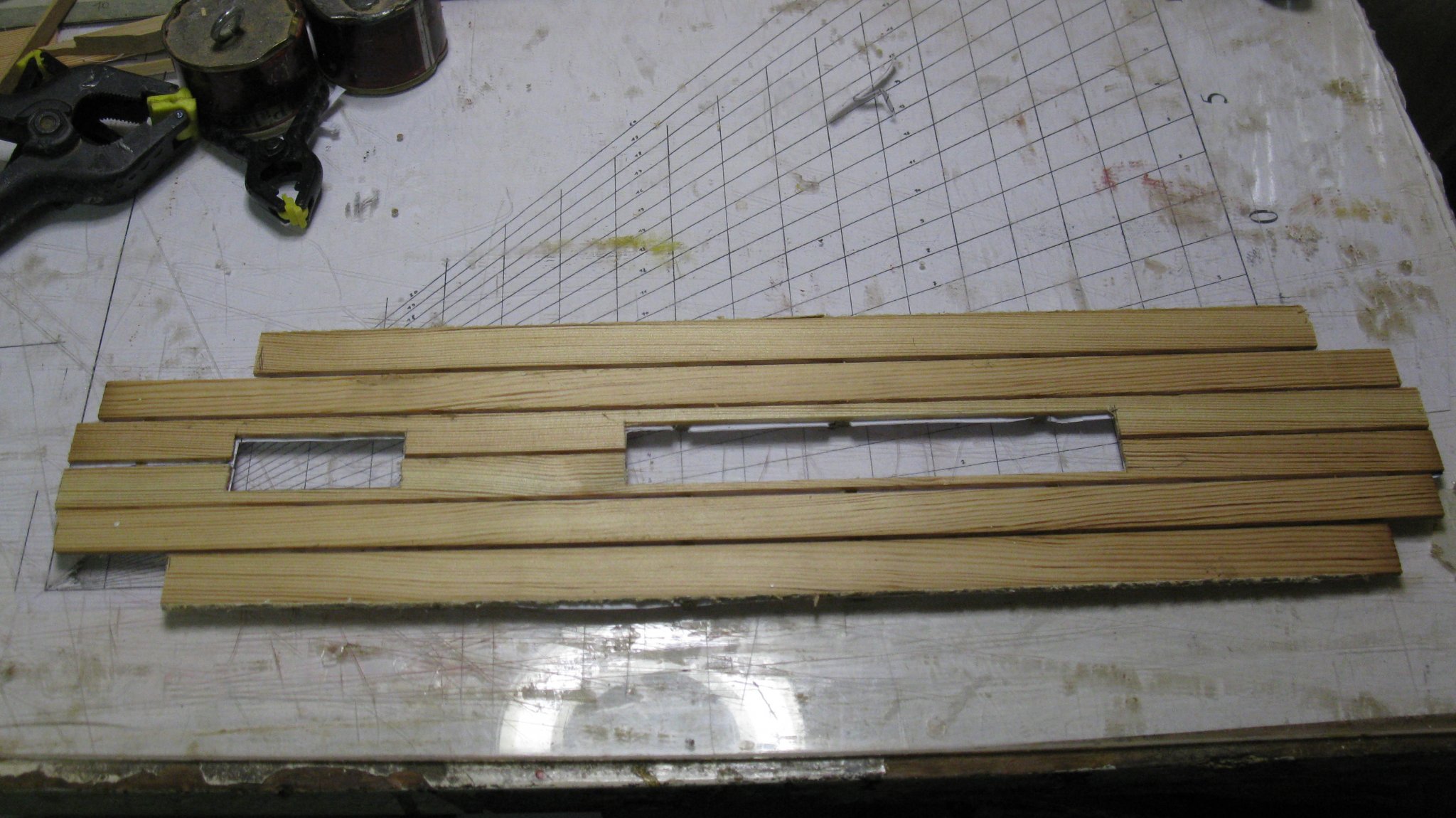
8.5. The bottom boards
I make also a paper template to determine the shape of the bottom boards.

Gluing the bottom boards together.

And sawing them into shape.
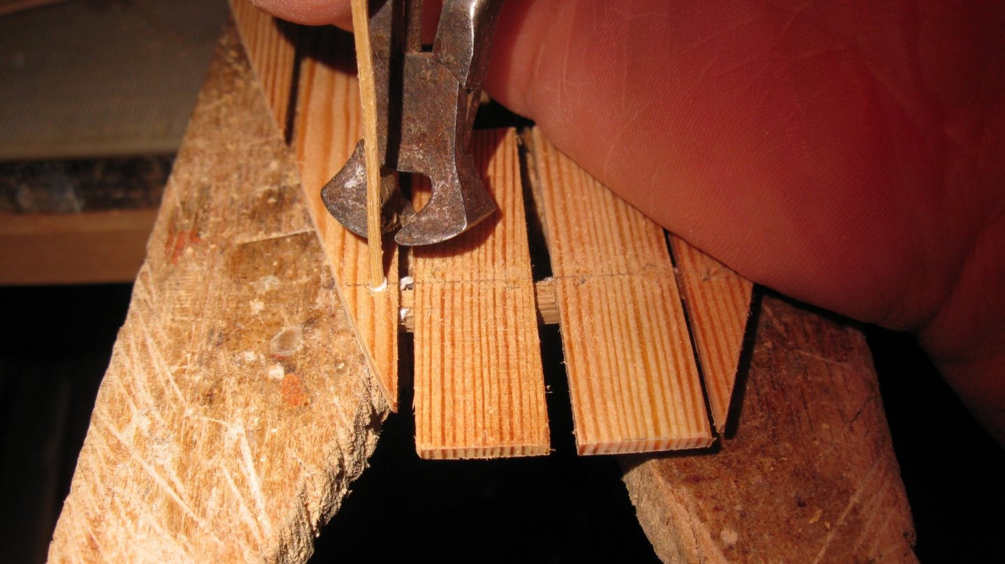
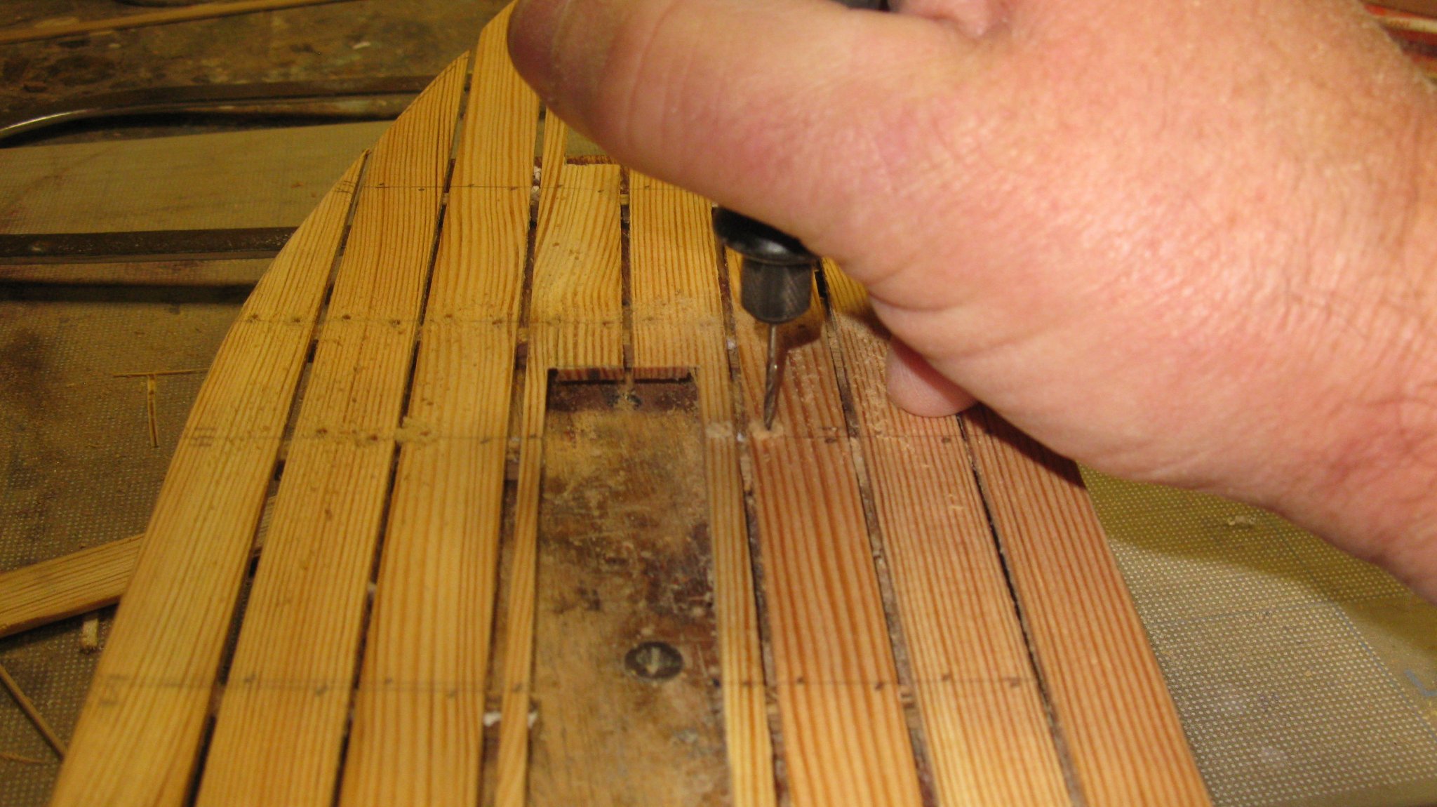
Drilling holes for tree nails. The attentive viewer will see that I added a plank at both sides of the board. When I fitted the board, it was much too narrow. There was plenty of room to add a plank.

Placing bamboo tree nails.
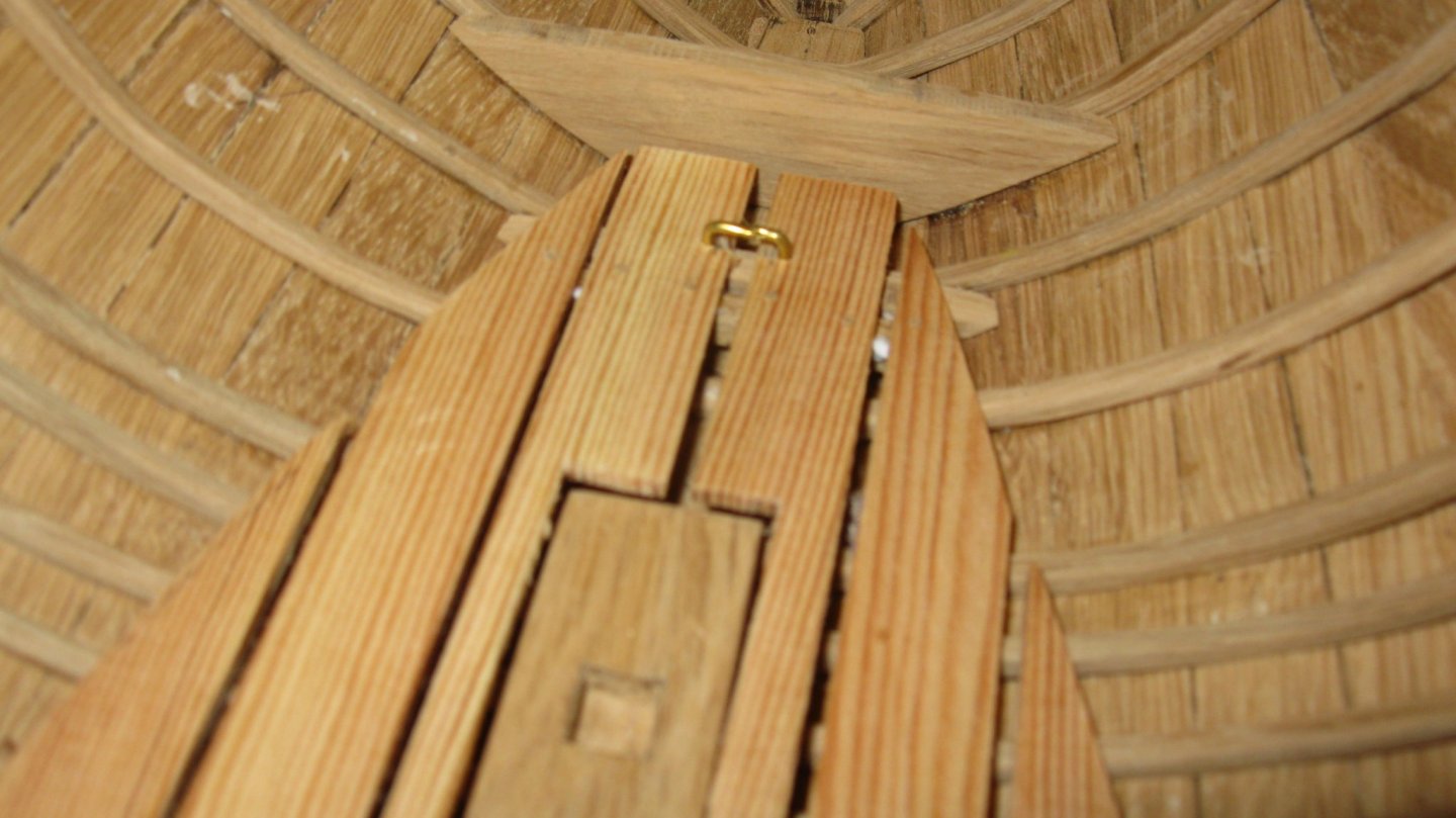
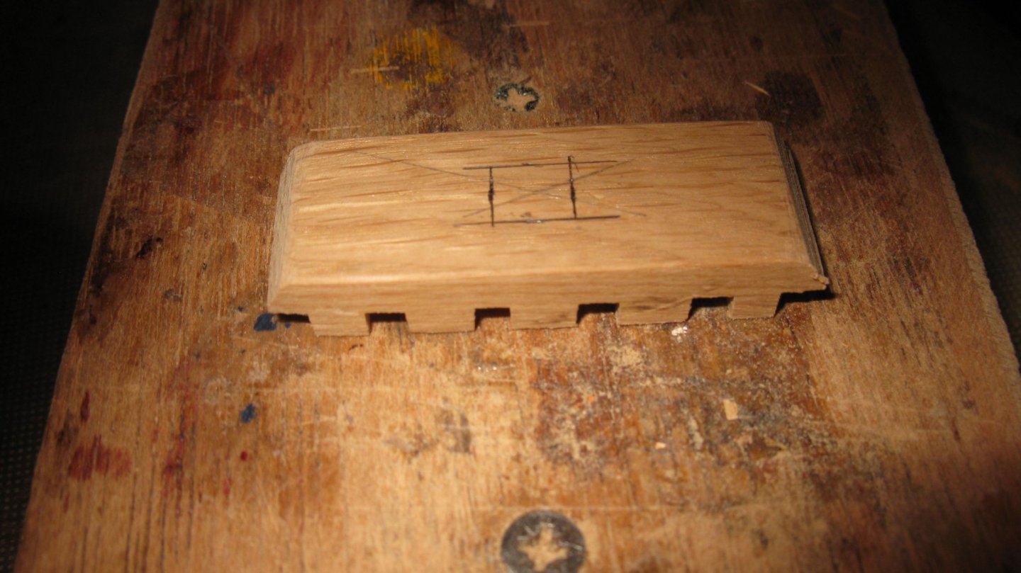
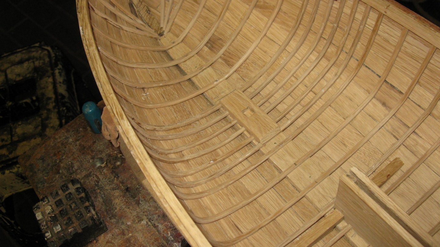
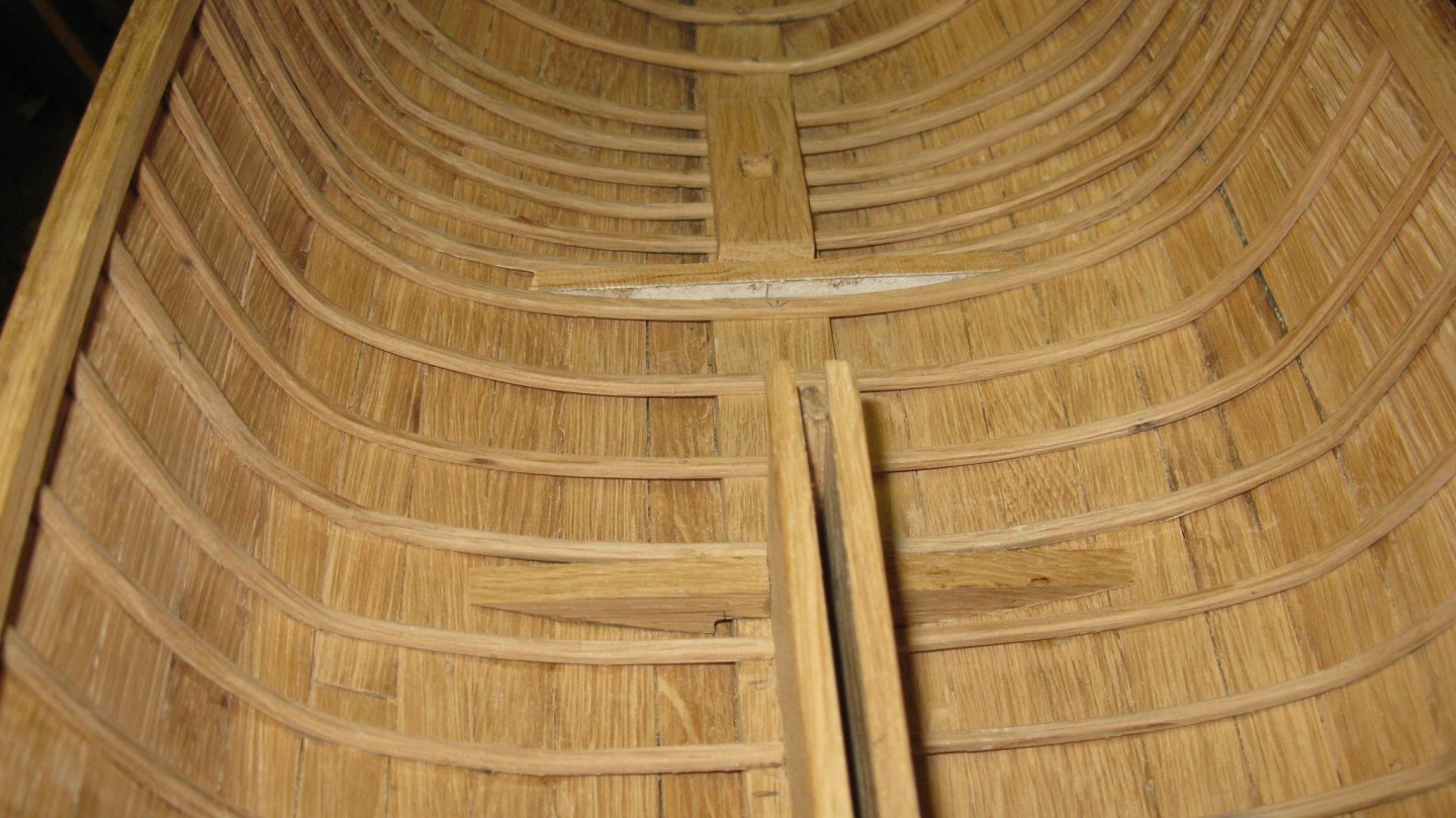
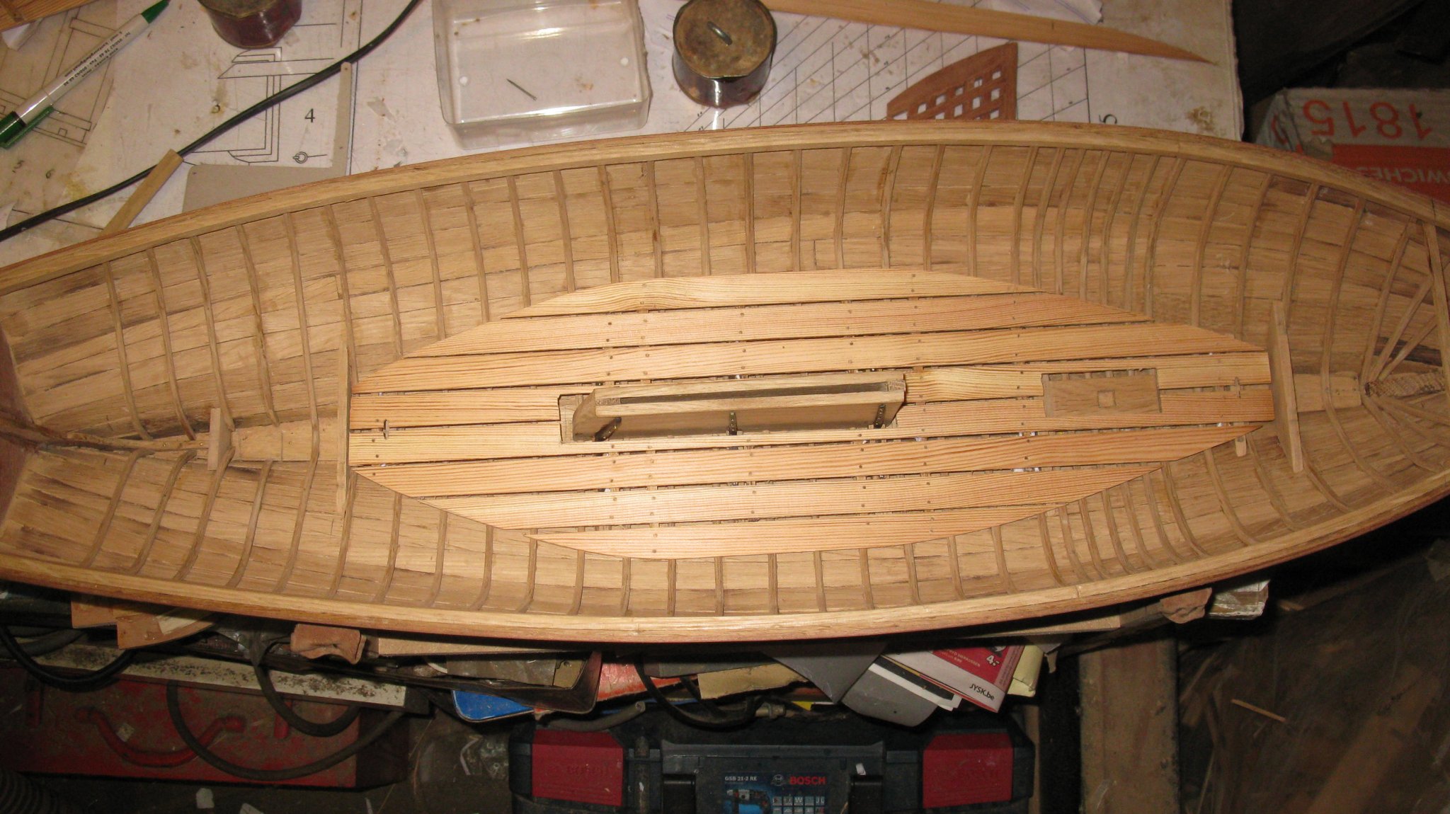
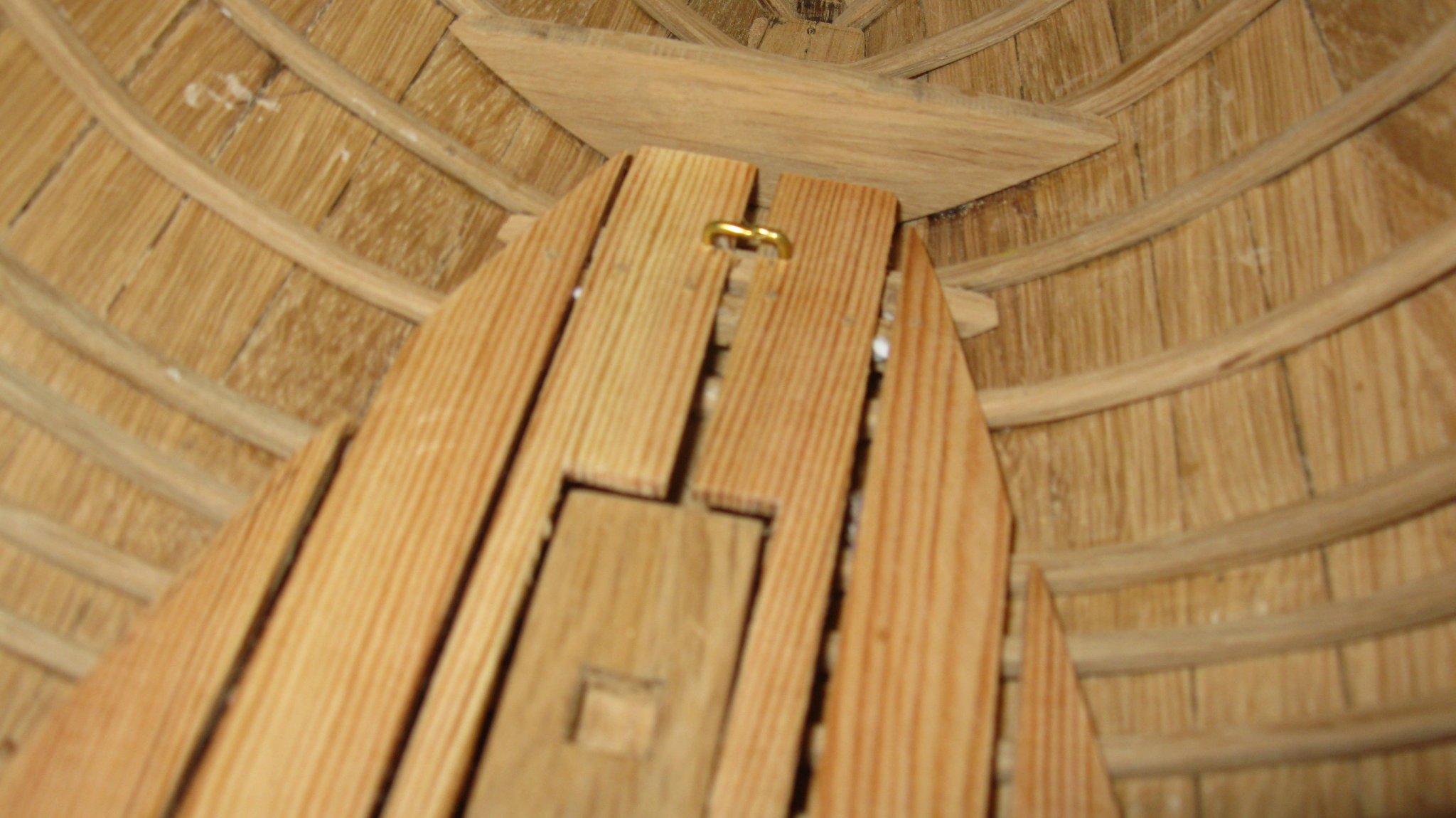
The central bottom board.
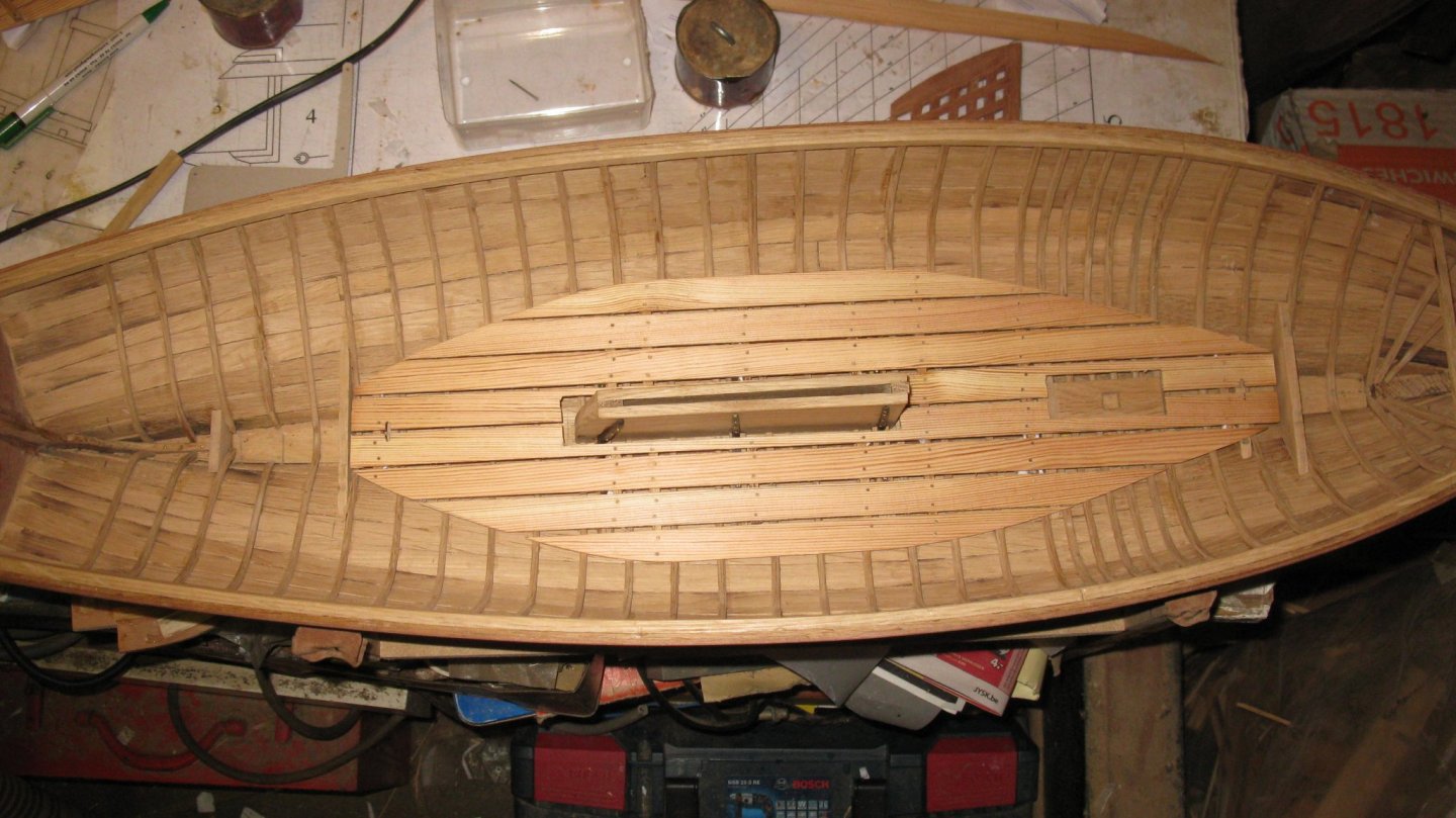
The three bottom boards
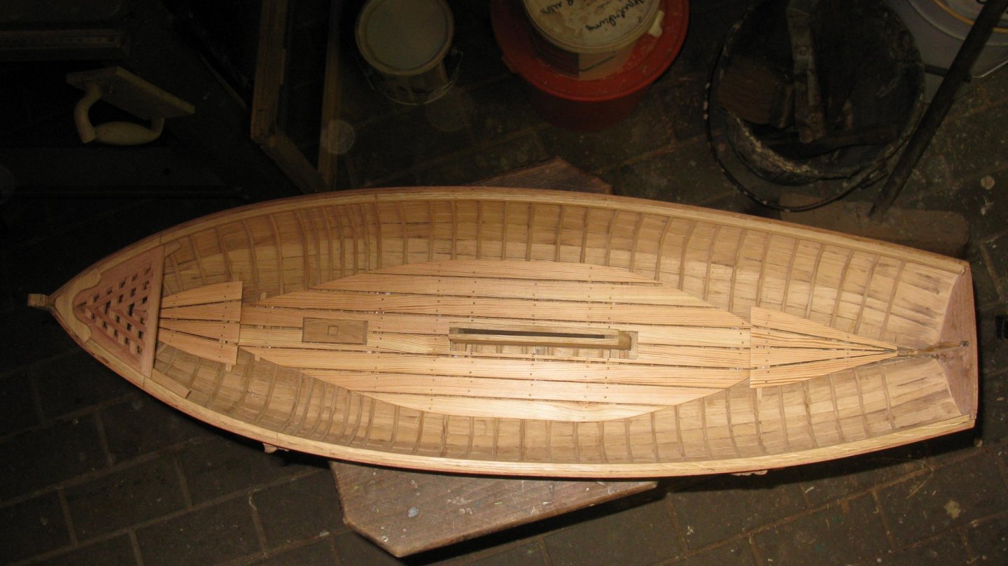
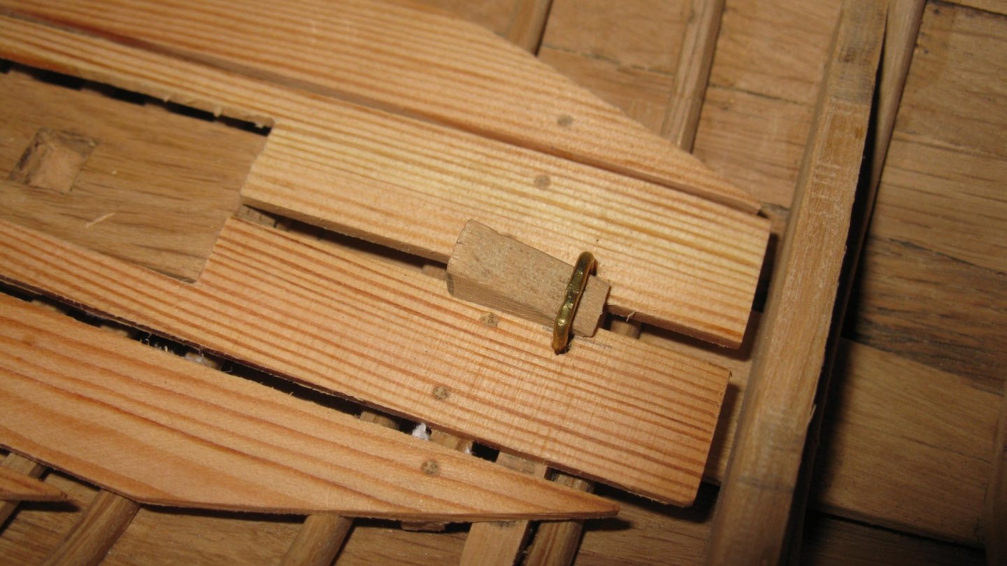
The central bottom board is secured with a bracket and a wedge.
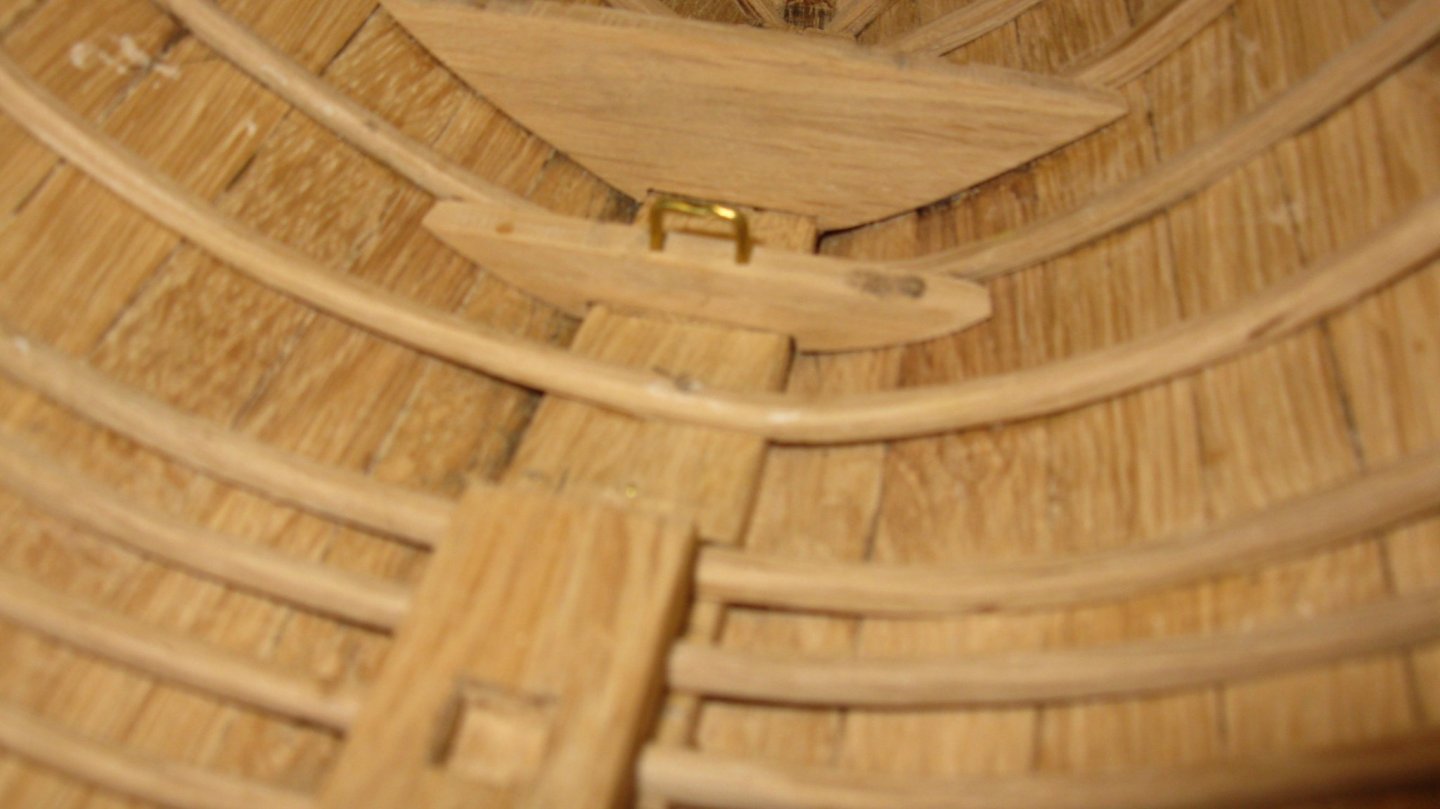
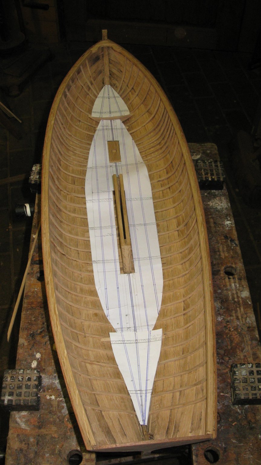
I place now also the knees of the center board case.
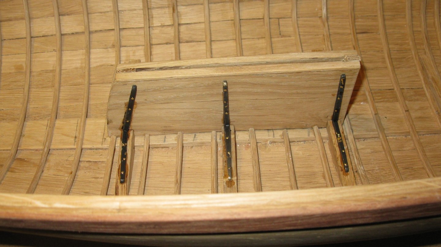
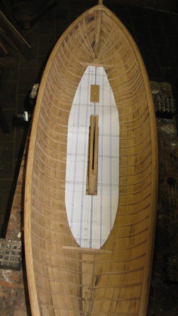
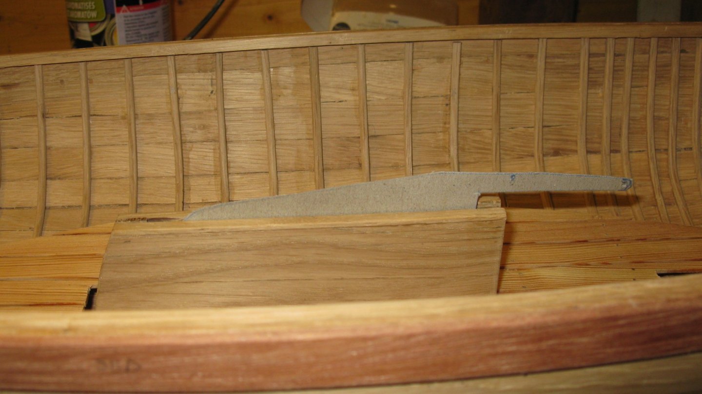
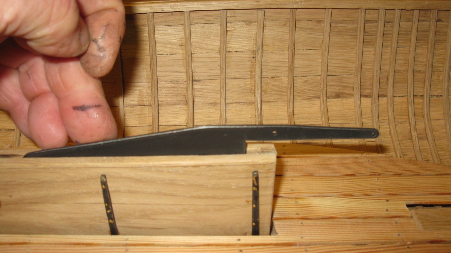
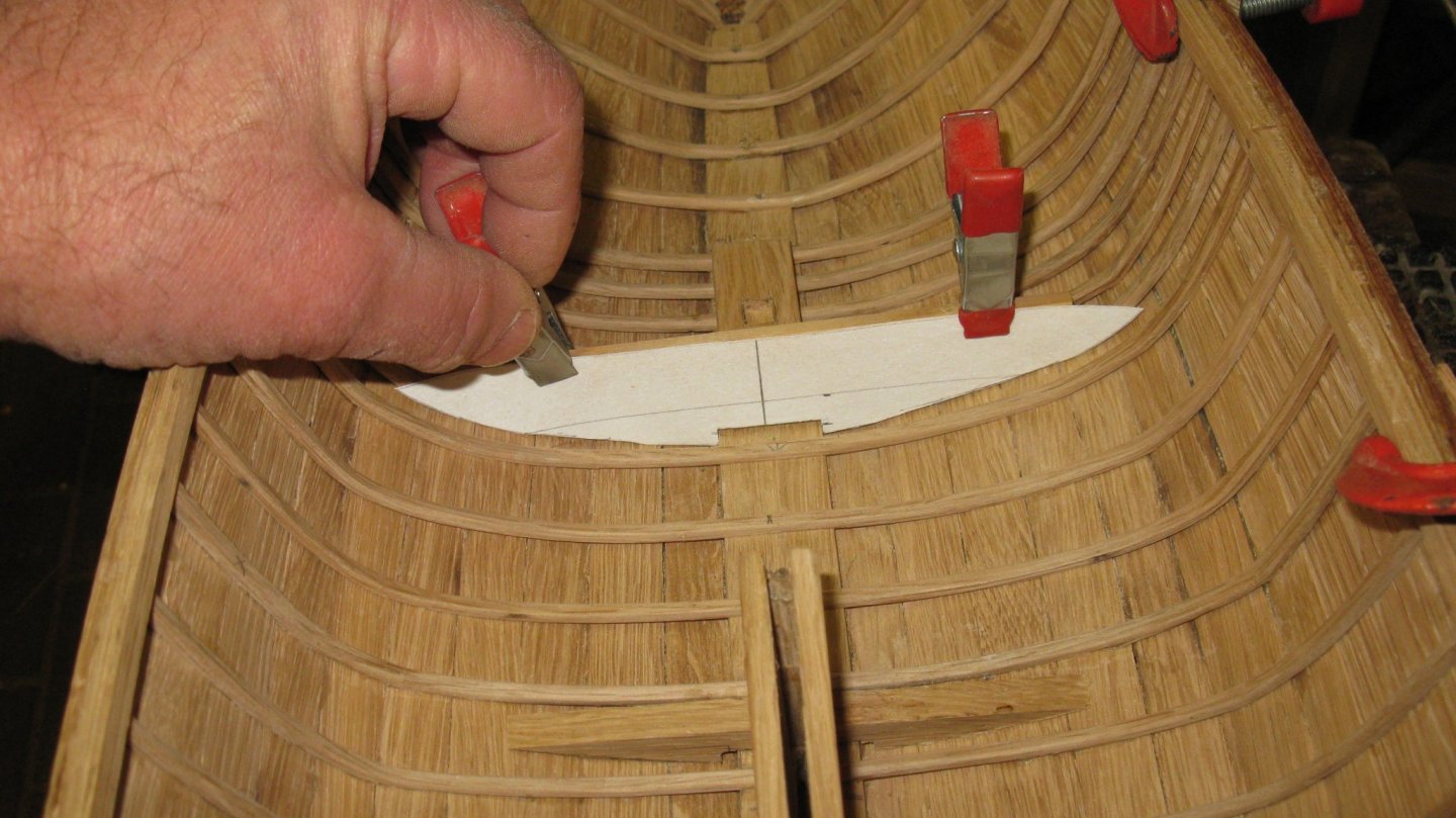
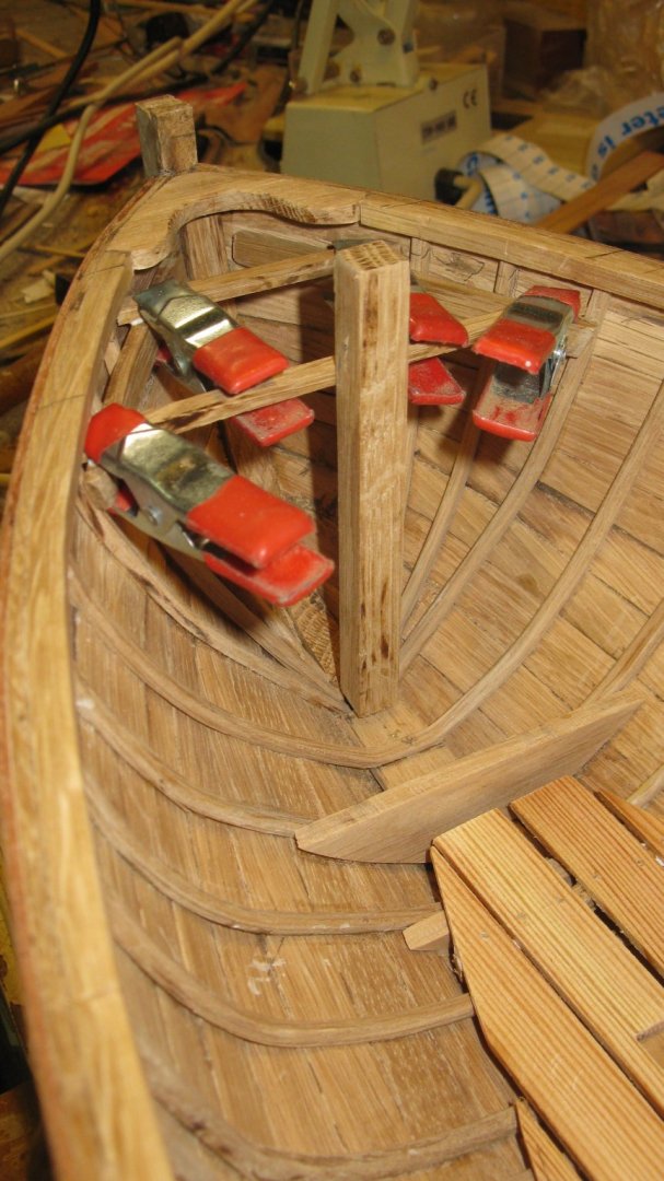
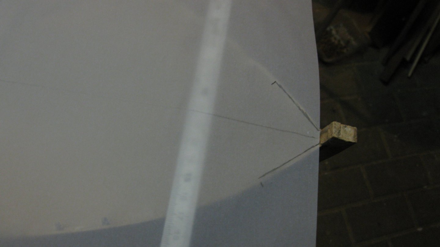
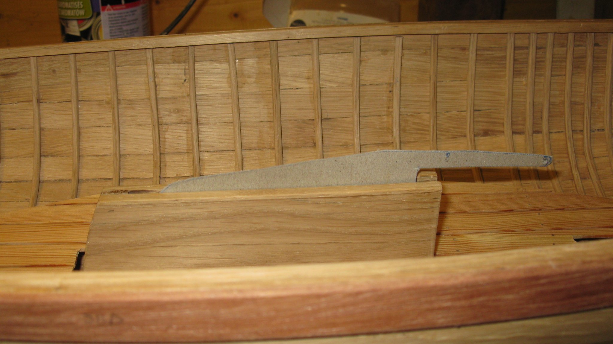
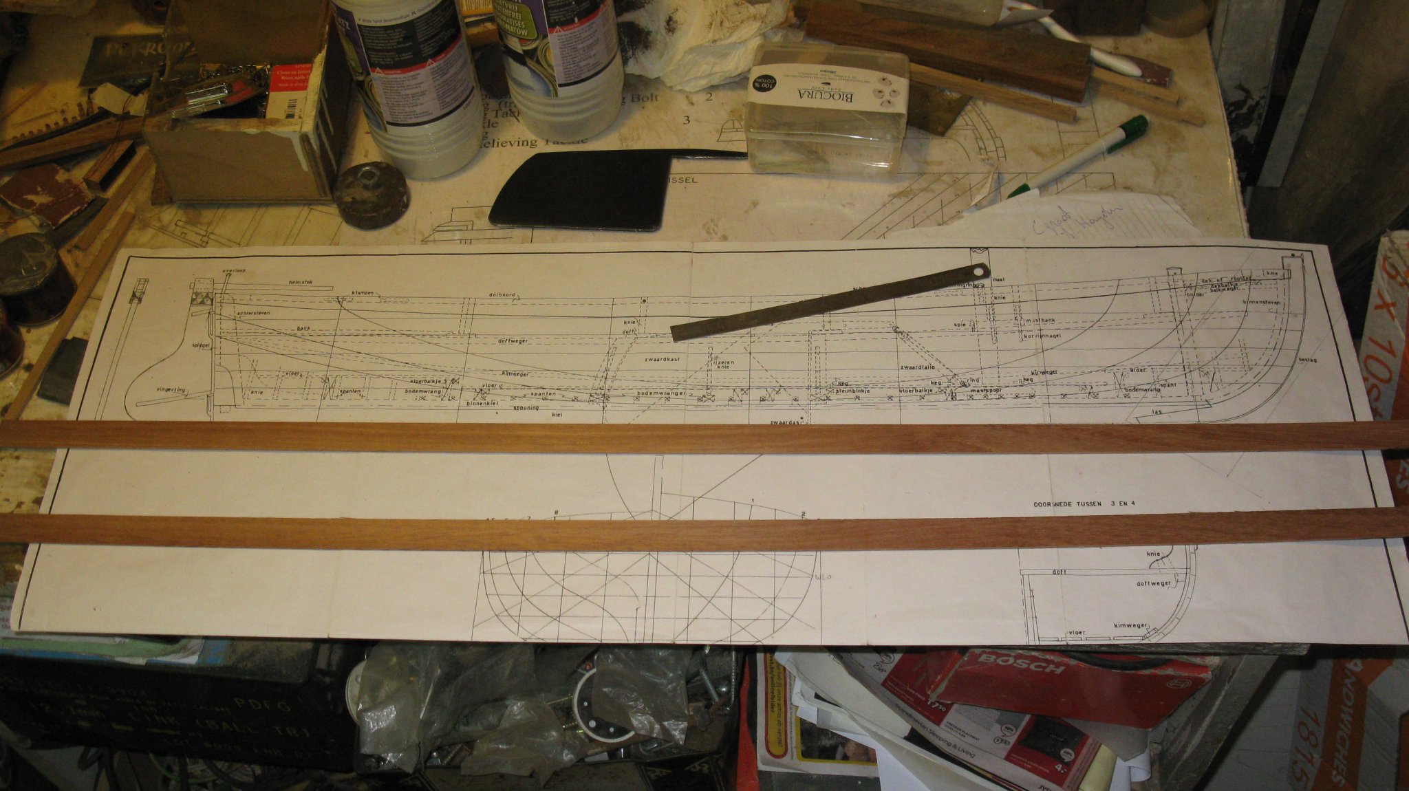
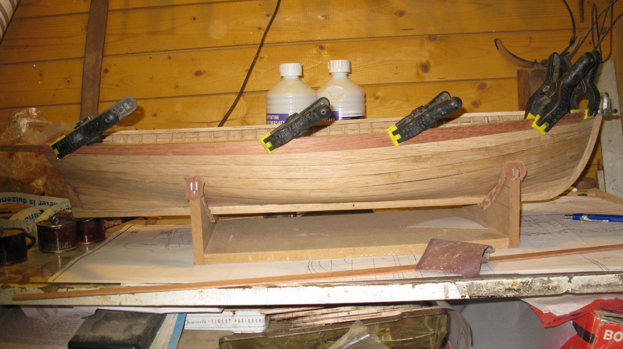
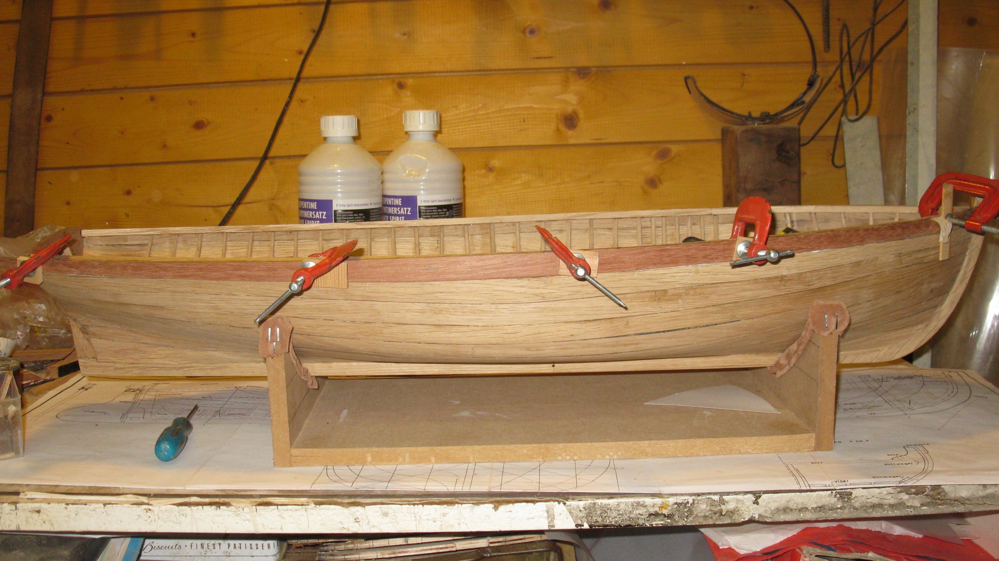
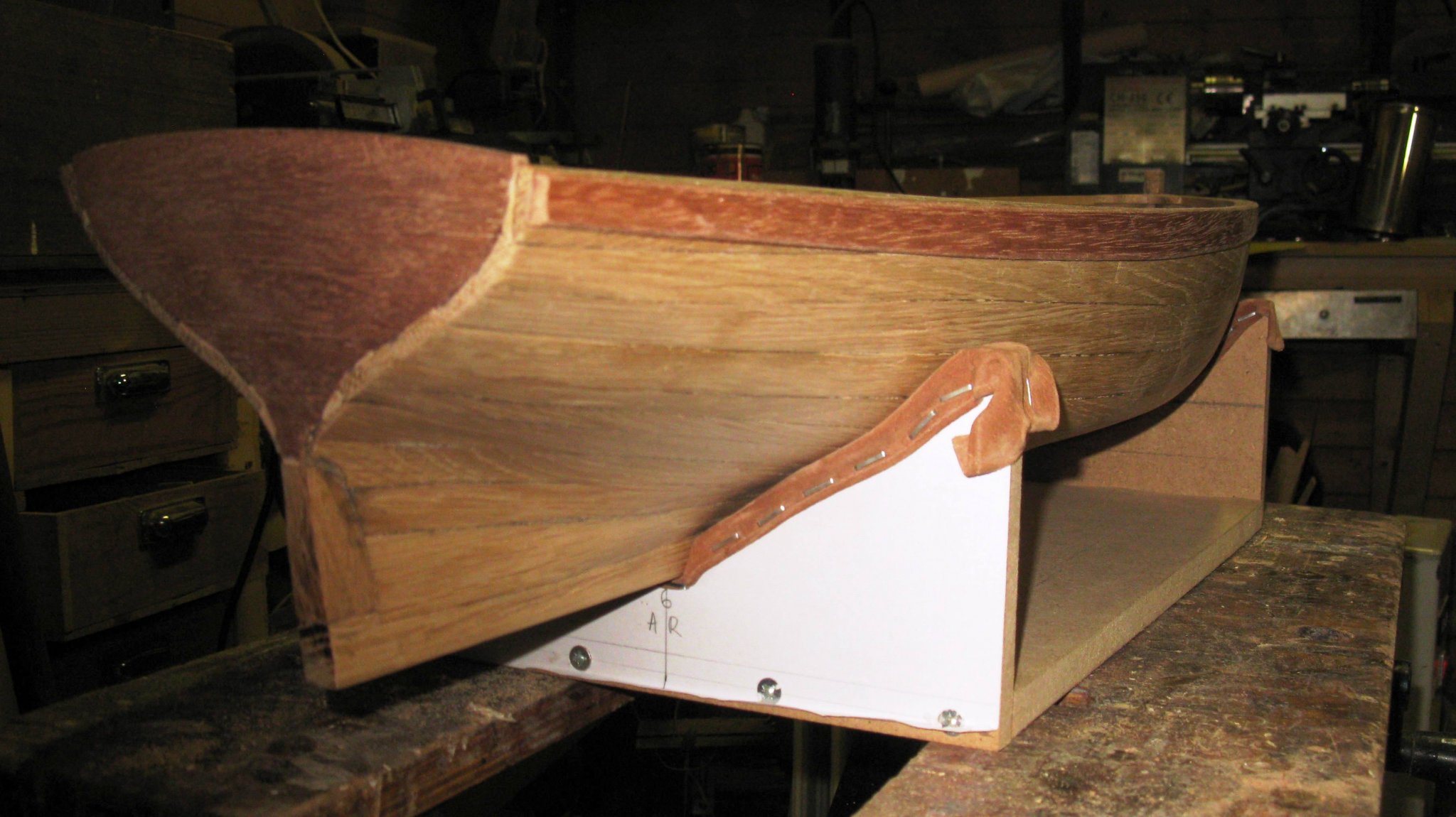
While working at the center board case and studying the plan, I discovered that something was wrong with the center board. Two thwarts will be laying on the center board. It is hardly visible on the plan, therefore I colored the forward thwart red on the picture below. In hauled up position the arm of the center board must be high enough to give space for the thwart. Mine does not (see inset: the board is even not yet fully hauled up and there is no place for the thwart).
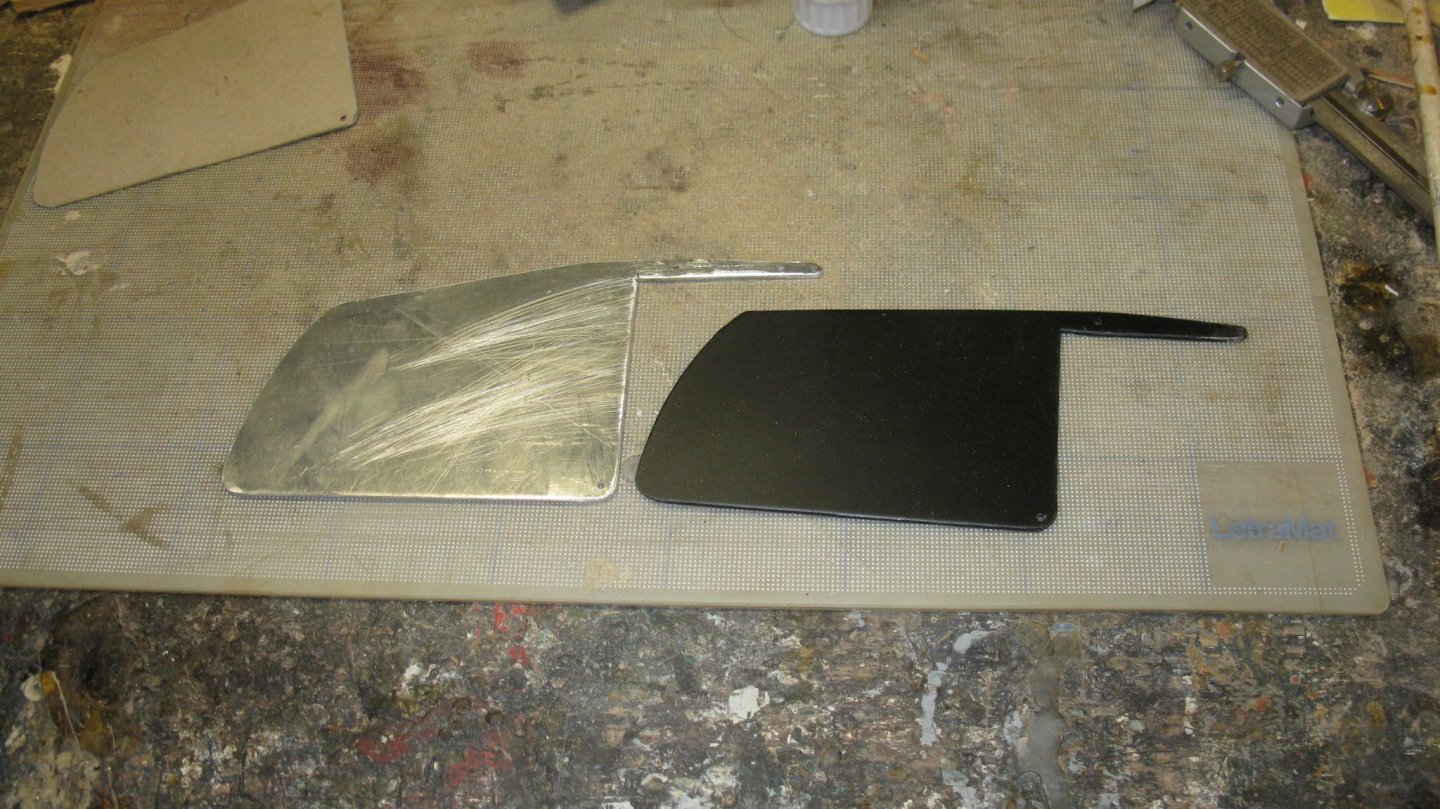
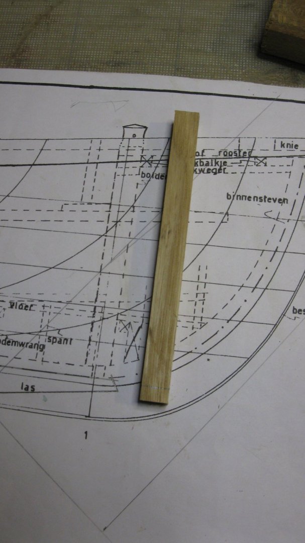
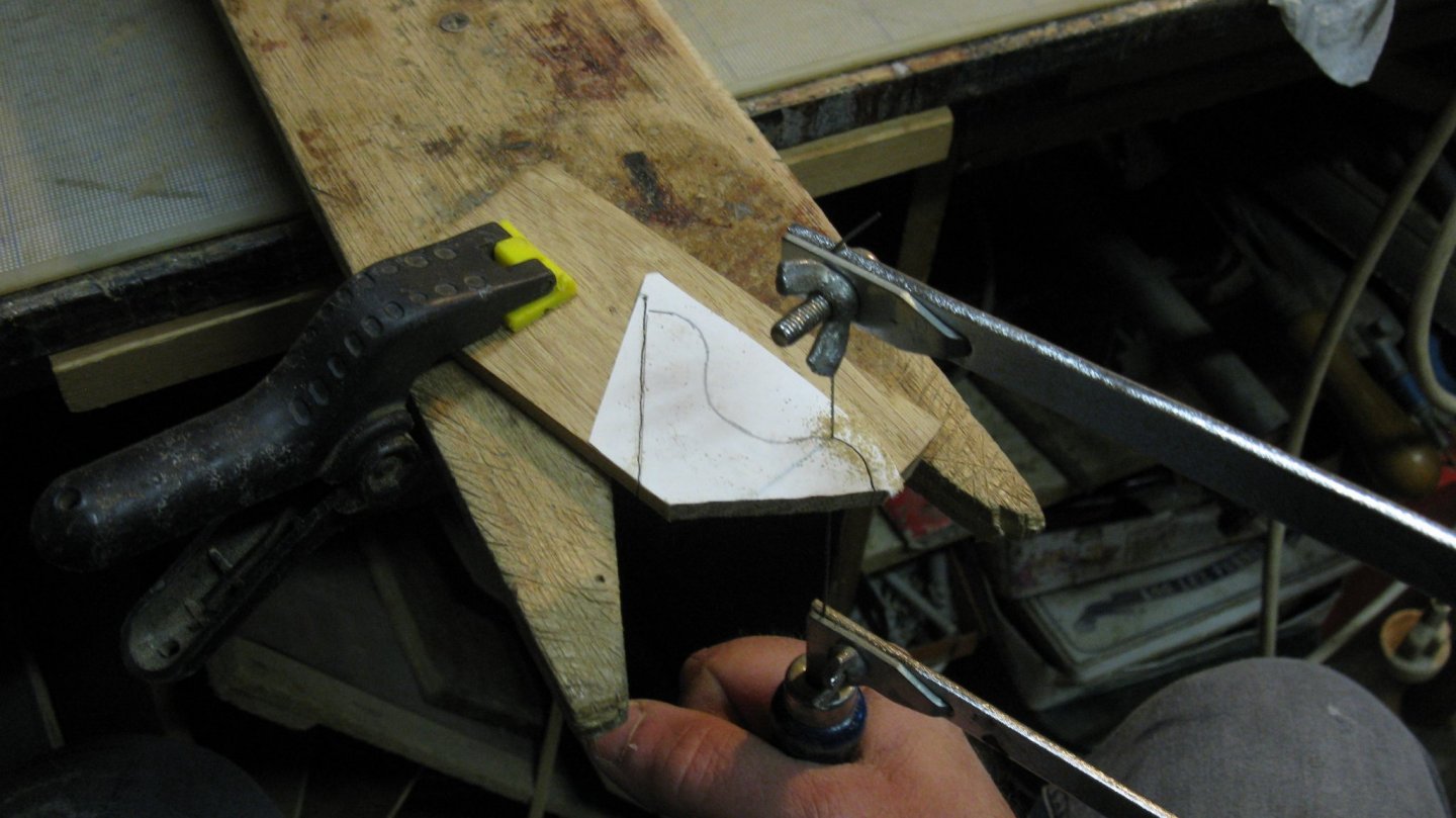
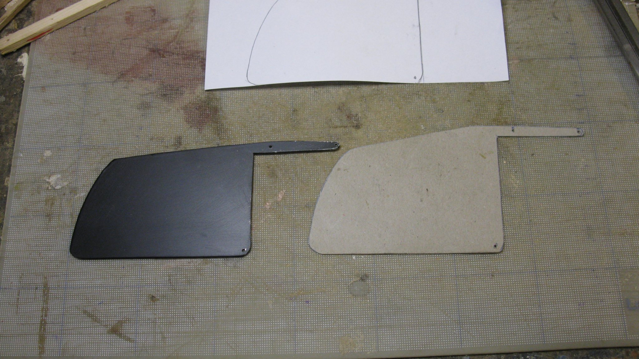
I have to make a new, adapted center board. I make first a card board mock up to try it in both hauled up and lowered position. On the first picture you see the original center board to the left.

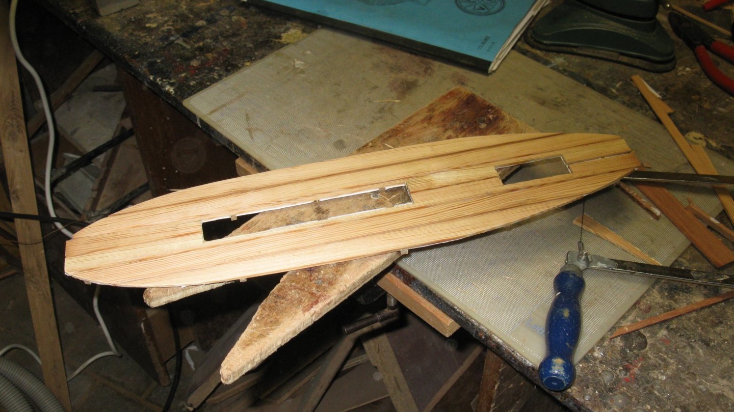
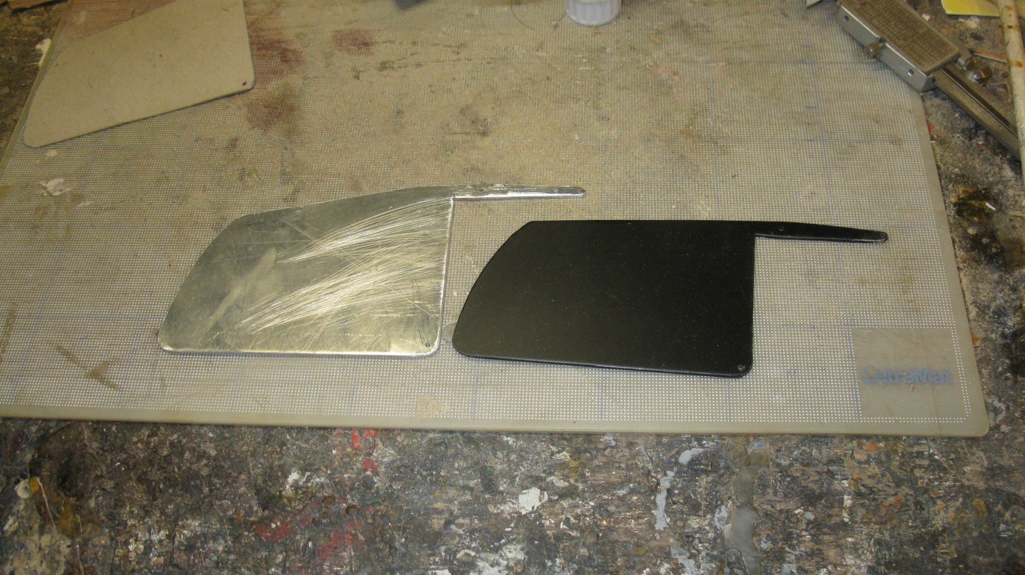
Now I make it in aluminum. The new one to the left, the old one to the right.
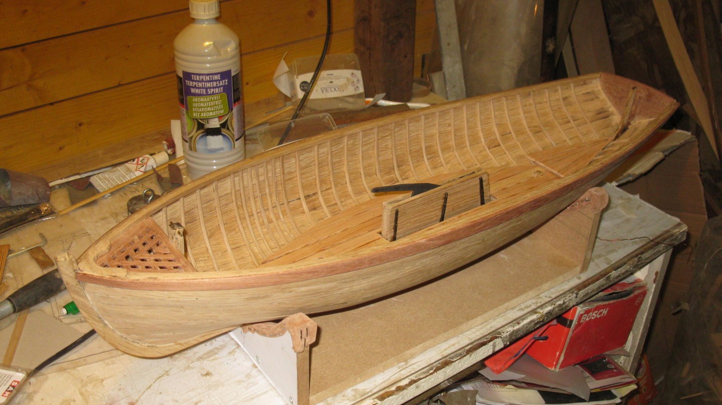
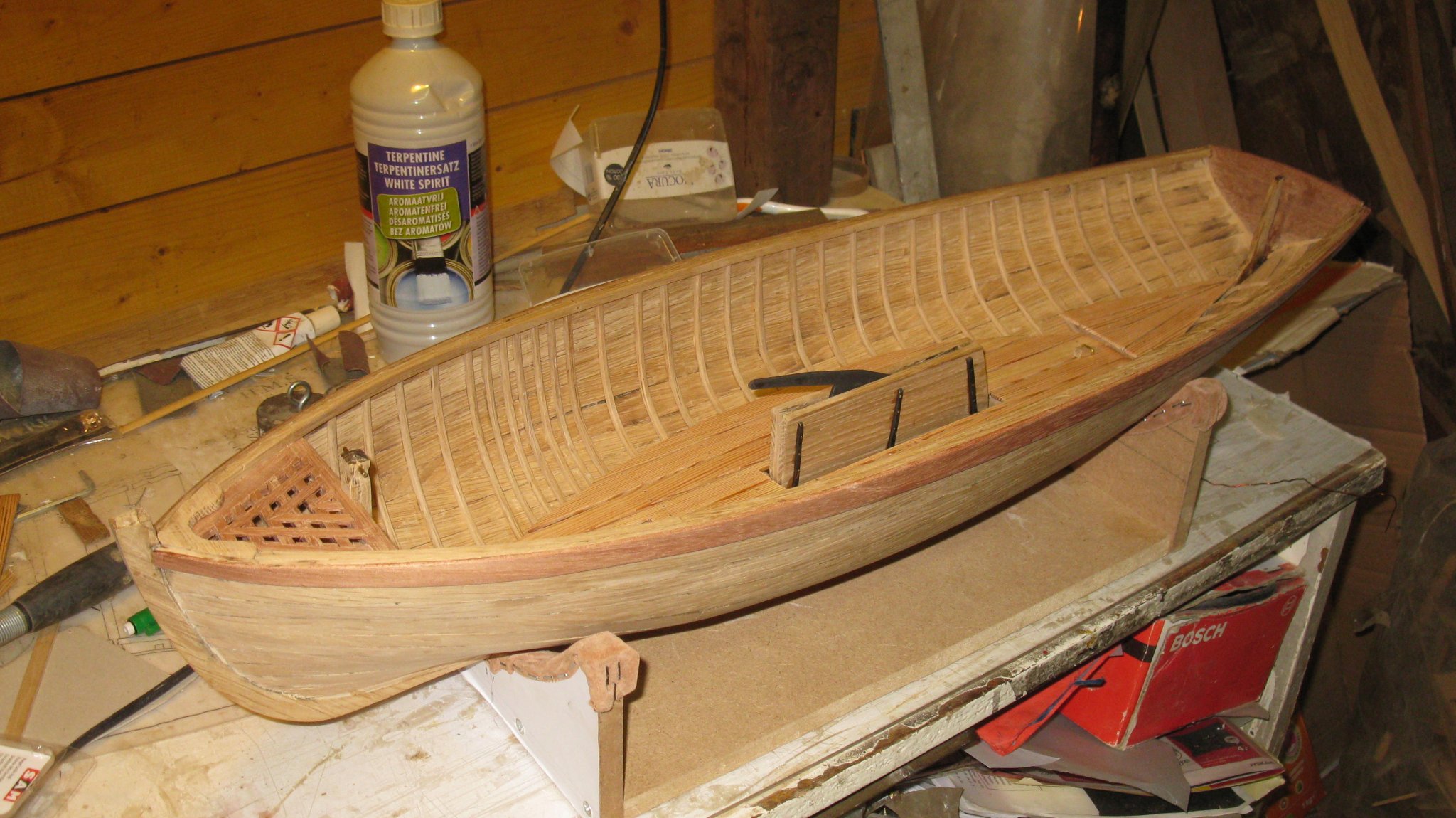
The new center board in hauled up position. Now there is place for the thwart.
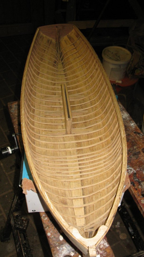
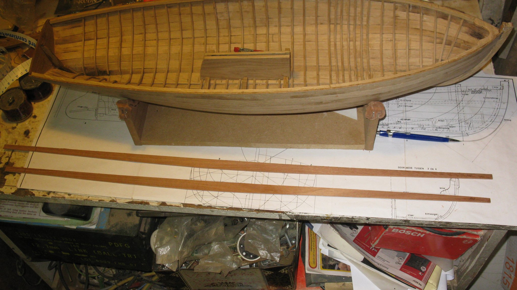
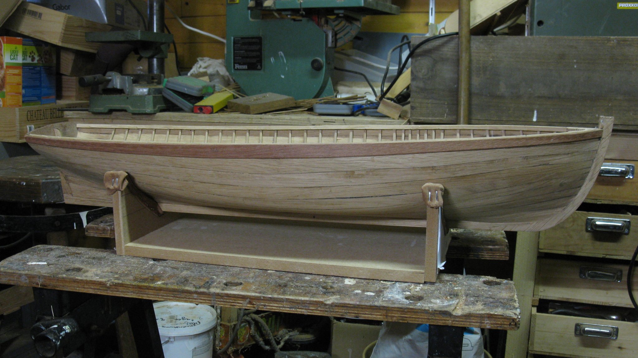
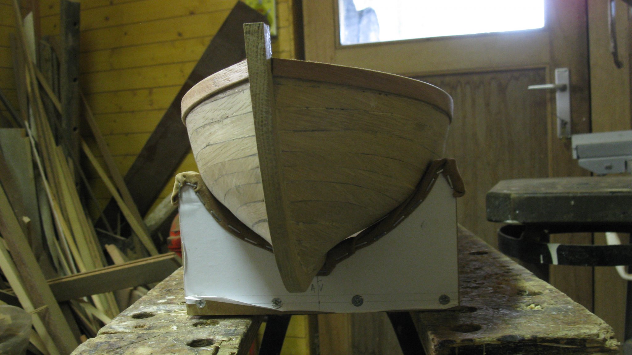
The boat as it is now.
Thank you to follow.
Thank you for the likes.
And thank you for the constructive comments.
Till next week!
- cog, IgorSky, Mirabell61 and 8 others
-
11
-
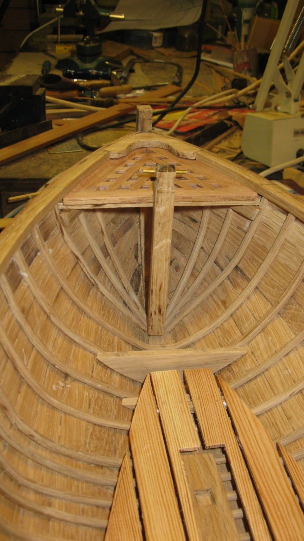
8.4. The mast step
Making the mast step.

The mast step into place.
- druxey, GrandpaPhil, FriedClams and 4 others
-
7
-
8.3. The floor timbers
I make paper templates to find the shape of the floor timbers.
Fitting, refining, again fitting, adjusting, ....

To obtain finally the good shape.
The floor timbers into place.

- GrandpaPhil, mtaylor, druxey and 3 others
-
6
-
On 10/19/2019 at 7:44 PM, vaddoc said:
Very nice Geert! Your boat has a wooden loveliness, a pleasure to follow!
On 10/19/2019 at 7:54 PM, KeithAug said:The grating turned out very well - well done.
Thank you very much for the appreciation, Vaddoc and Keith
On 10/19/2019 at 8:37 PM, andante said:Simply beautiful. I love that scale.
I like to work at large scales (1/25 and below). It goes better together with my thick short fingers to make things and it is easier for me to look to sturdy ship models.
On 10/24/2019 at 6:22 AM, FriedClams said:This boat is coming along great G.L. Good idea using a wallpaper steamer for the steam box. The framing and grating turned out sweet - very nice. And I enjoy the detailed description of your work process - thanks.
Gary
Thanks Gary, I learn a lot from the way you describe your build of the New England Stonington Dragger.
- mtaylor and FriedClams
-
2
-
-
I guess that the fauteuil in the wheelhouse is not fot the helmsman 😁.
- Canute, popeye the sailor, mtaylor and 1 other
-
4
-
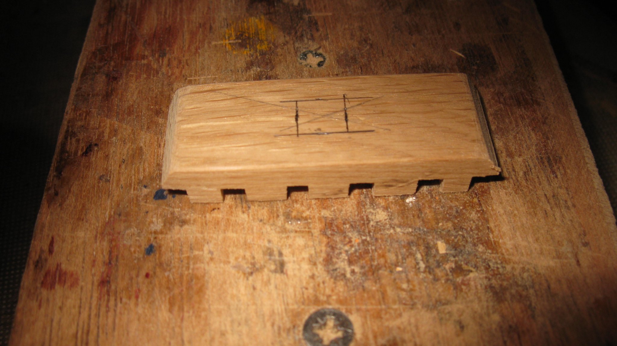
8.2. The mooring bit
I take an oak stock of 1x1 cm to make the mooring bit.
I first saw the fixing pin at the bottom of the bit.
Fitting the bit in the hull.
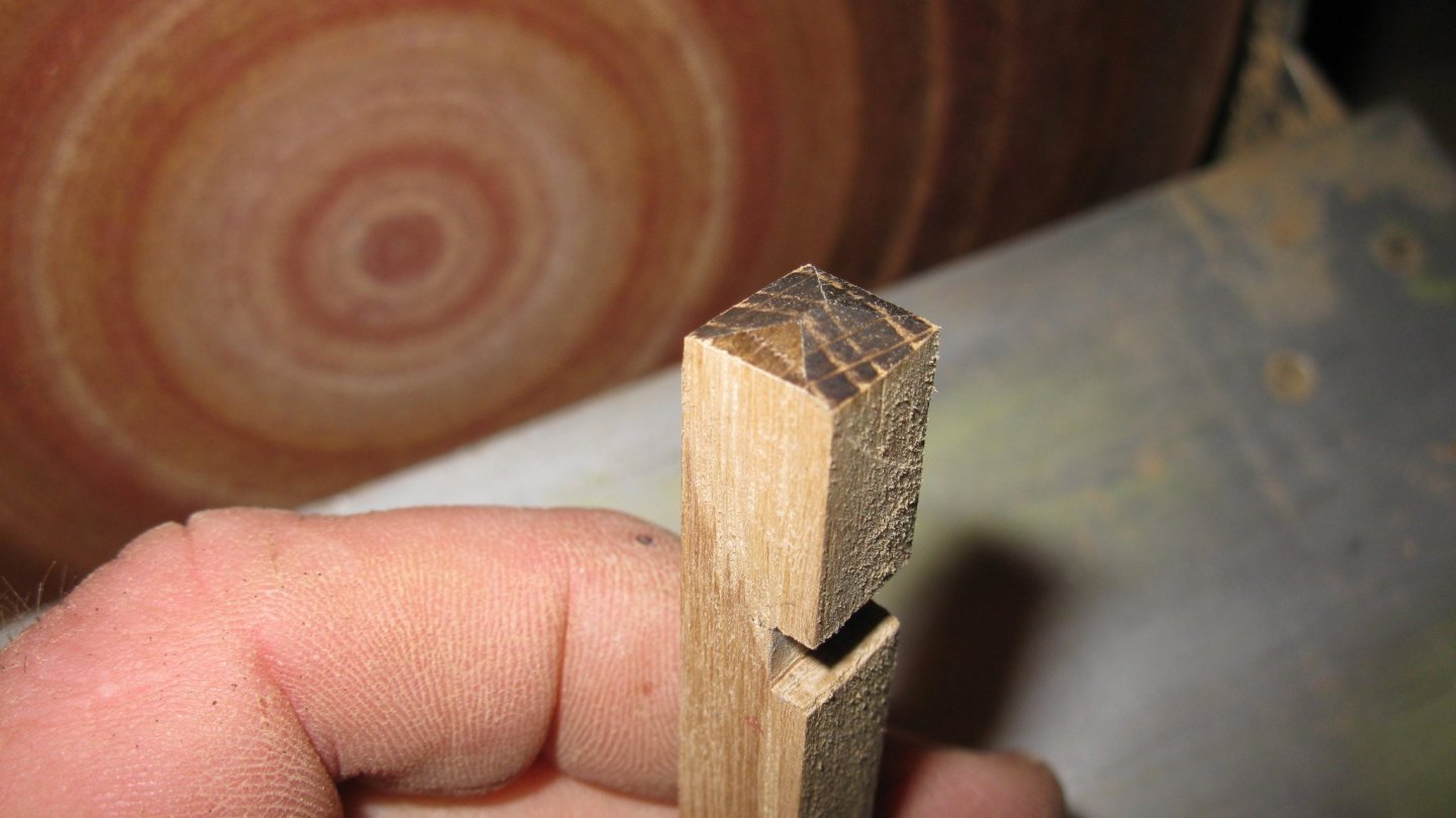
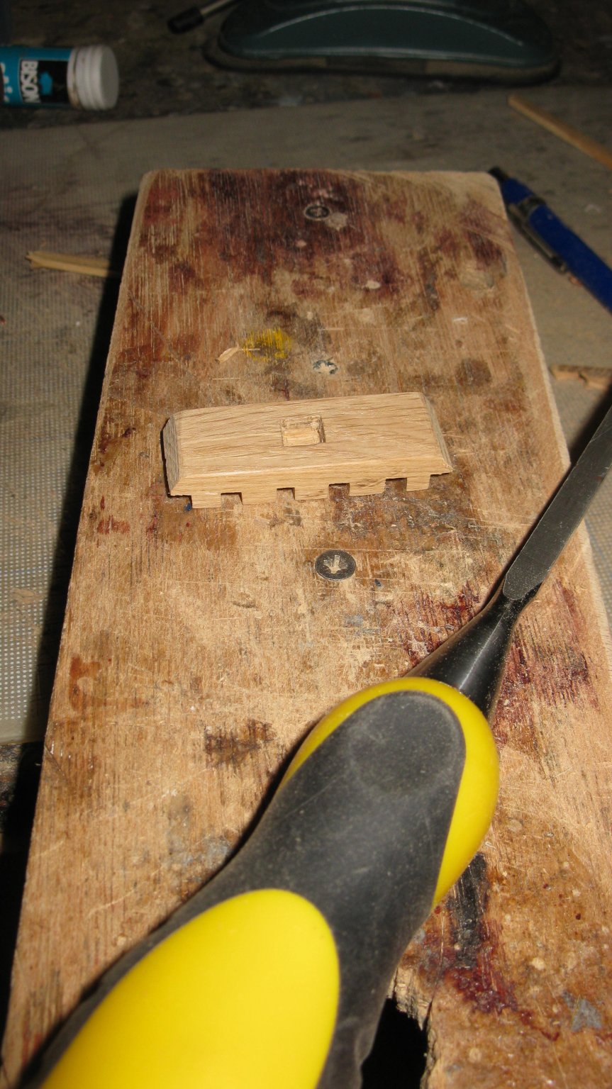
Shaping the top of the bit. The grating has to fit in the slot at the front of the bit.
Shaping the bit with the Dremel.
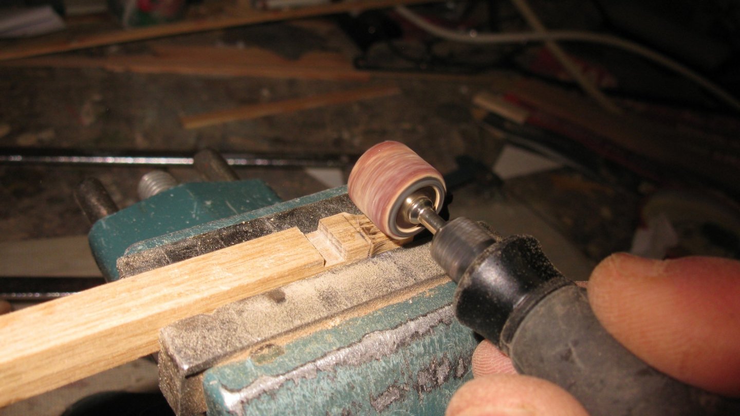
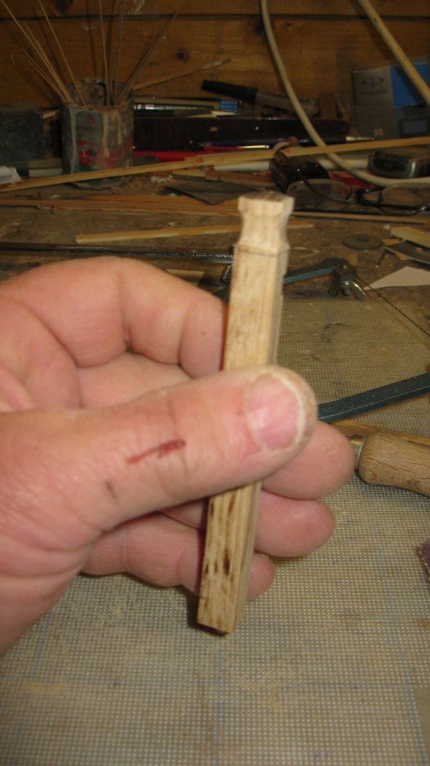
The mooring bit has a horizontal brass pin just below the top. Fitting the finished mooring bet.
Thank you to follow.
Thank you for the likes.
And thank you for the constructive comments.
Till next week!
- yvesvidal, GrandpaPhil, KeithAug and 9 others
-
12
-
Part 8. The inside of the boat
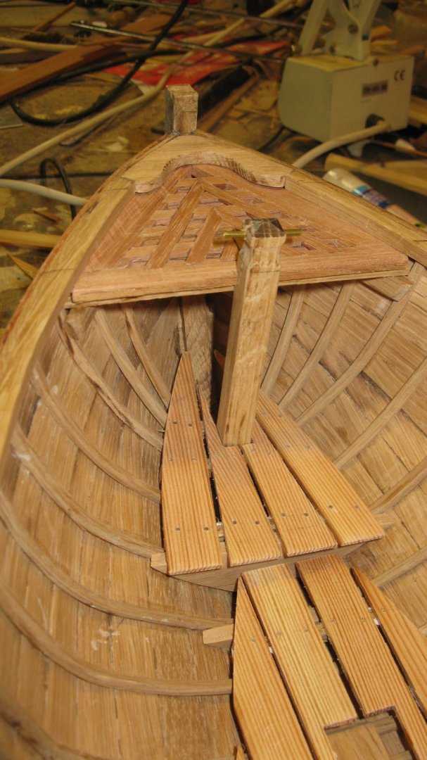
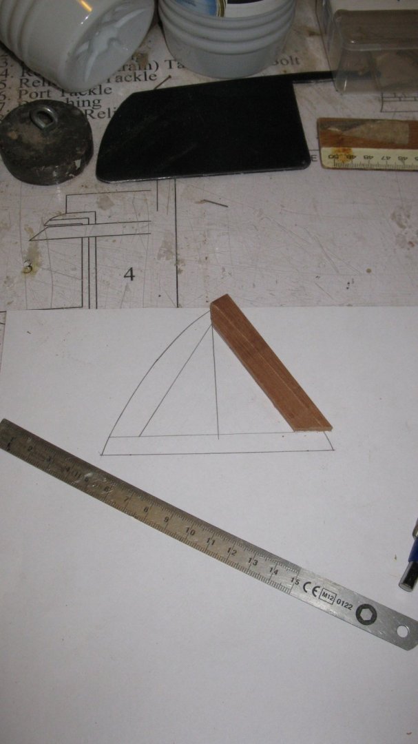
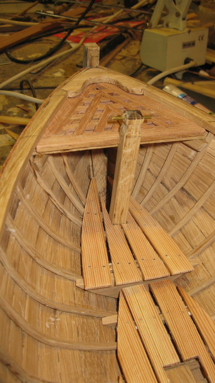
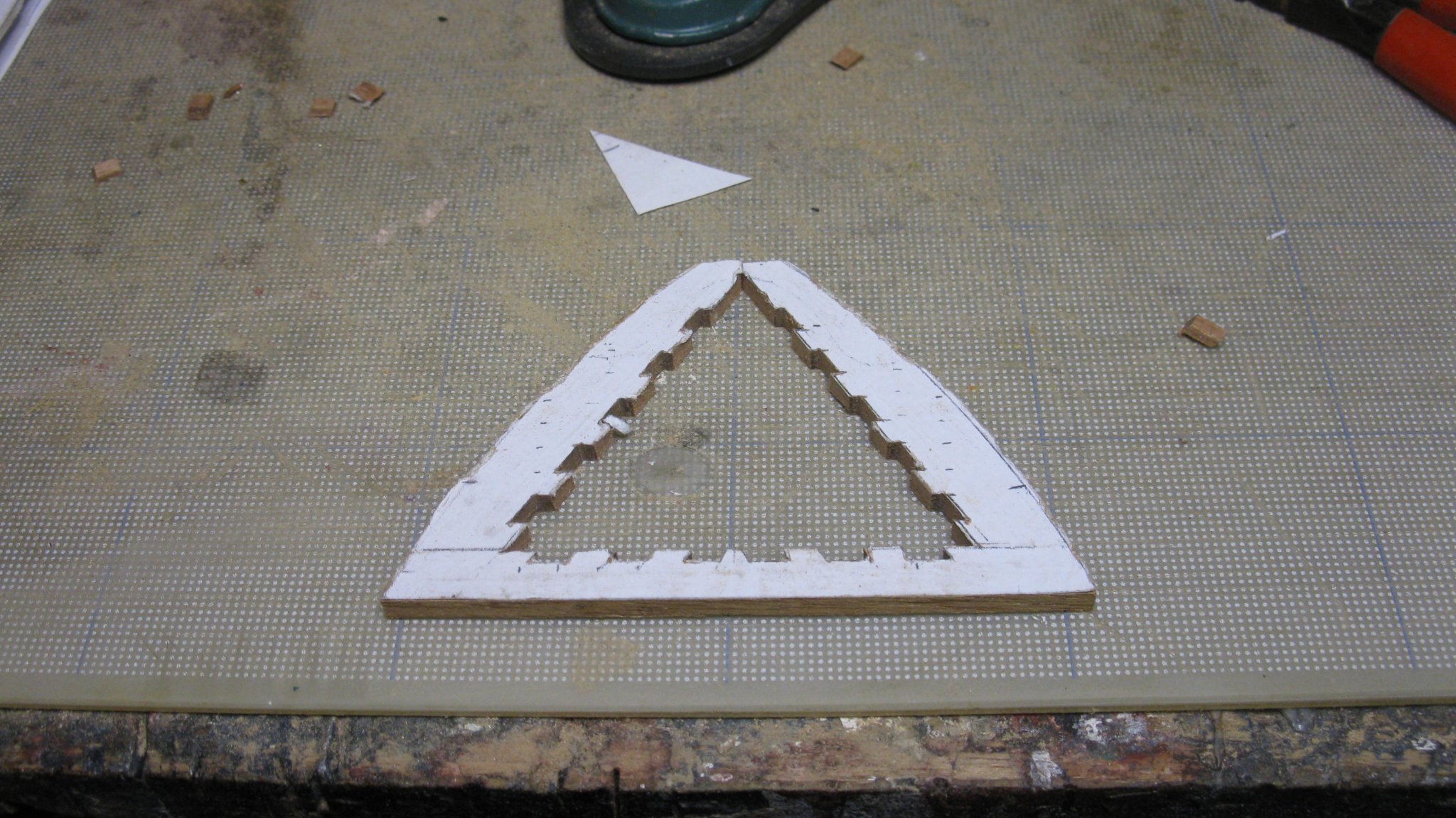
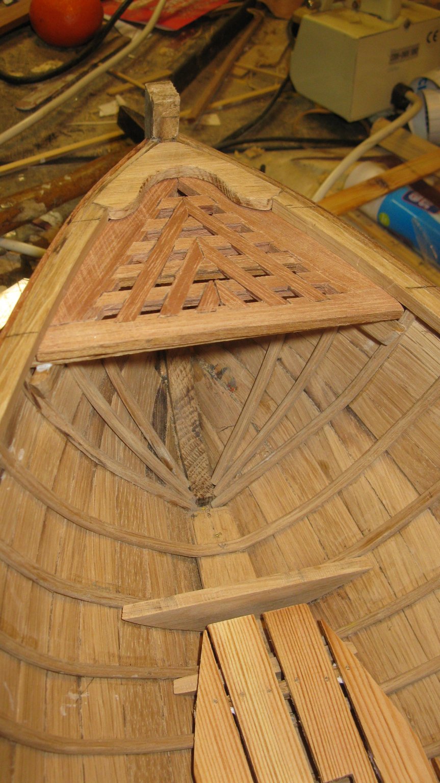
8.1. Grating for the fore castle
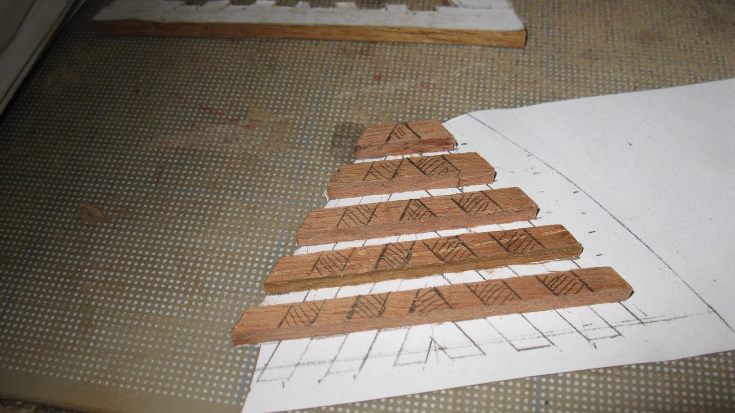
The boat has a small forecastle. For its realization, the tutorial suggests some options: a closed deck or a grating. For the grating it gives two examples. If I was building a full scale sailing boat I would chose for a closed deck to have at least one dry spot on board to place the picnic basket but as I am building a static boat model, I chose for a grating because it looks more stylish. I will try to make a grating like in the left example.
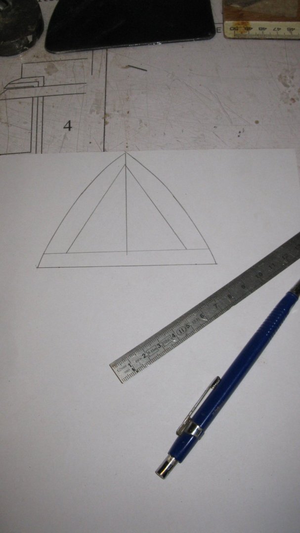
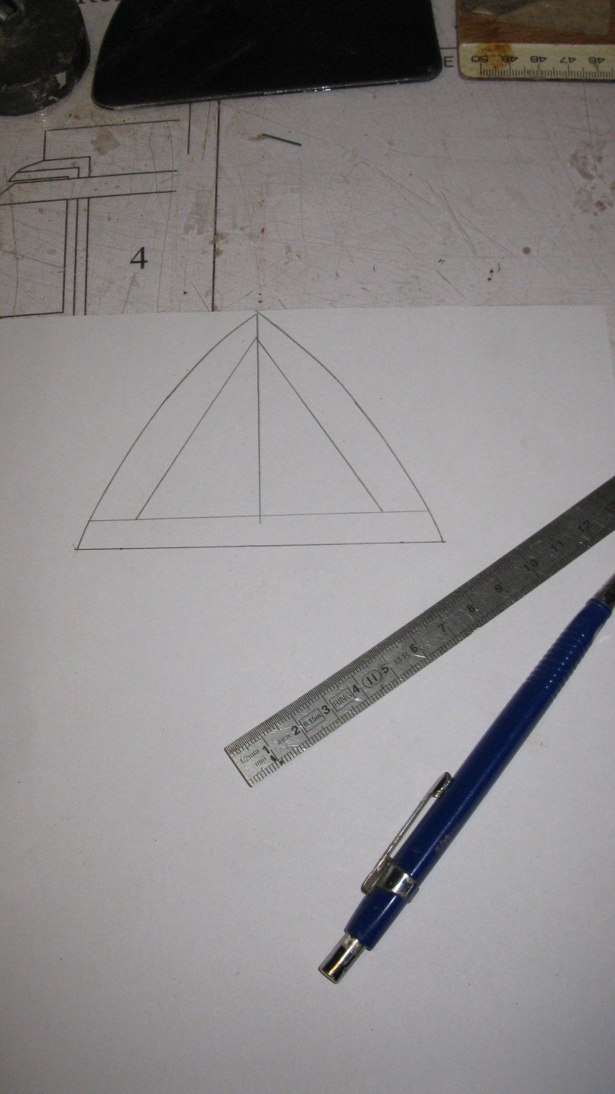
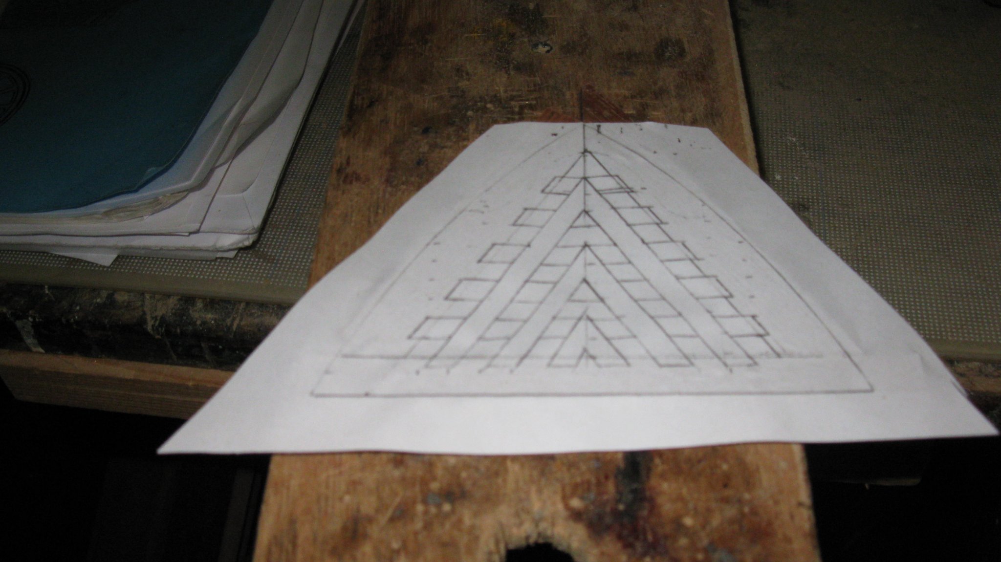
I start with making a paper design.
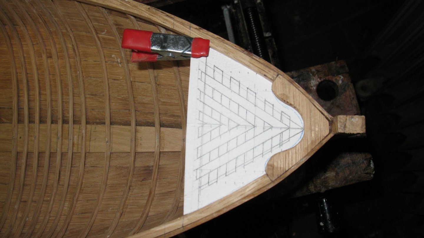
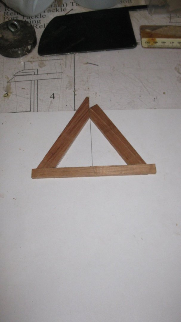
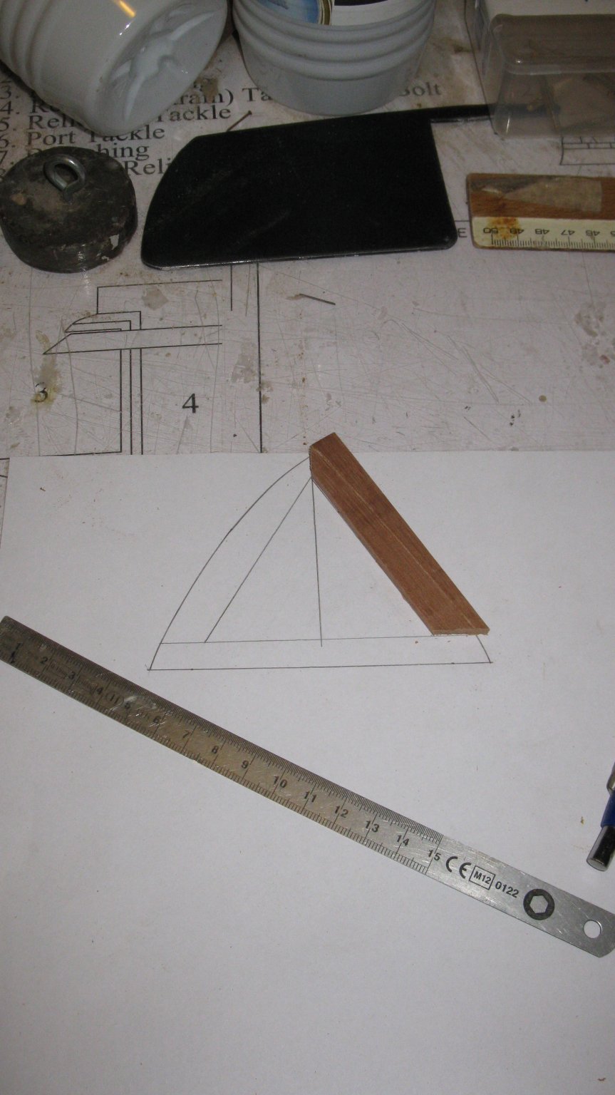
I make a photocopy of my design and trace the frame of my grating on the back side.
I glue three pieces of mahogany wood along the inner shape of the frame.
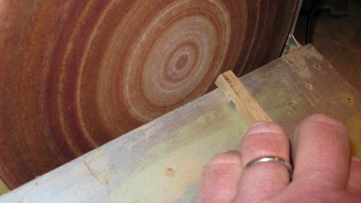
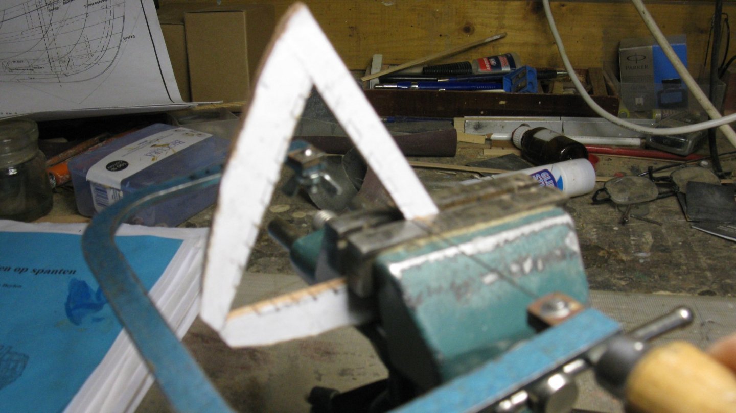
With the copy of the design on the other side, it is now easy to saw and sand the outer contours of the frame.

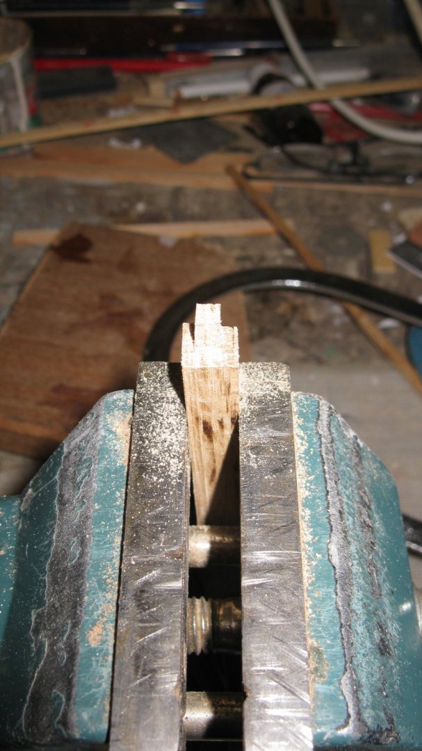
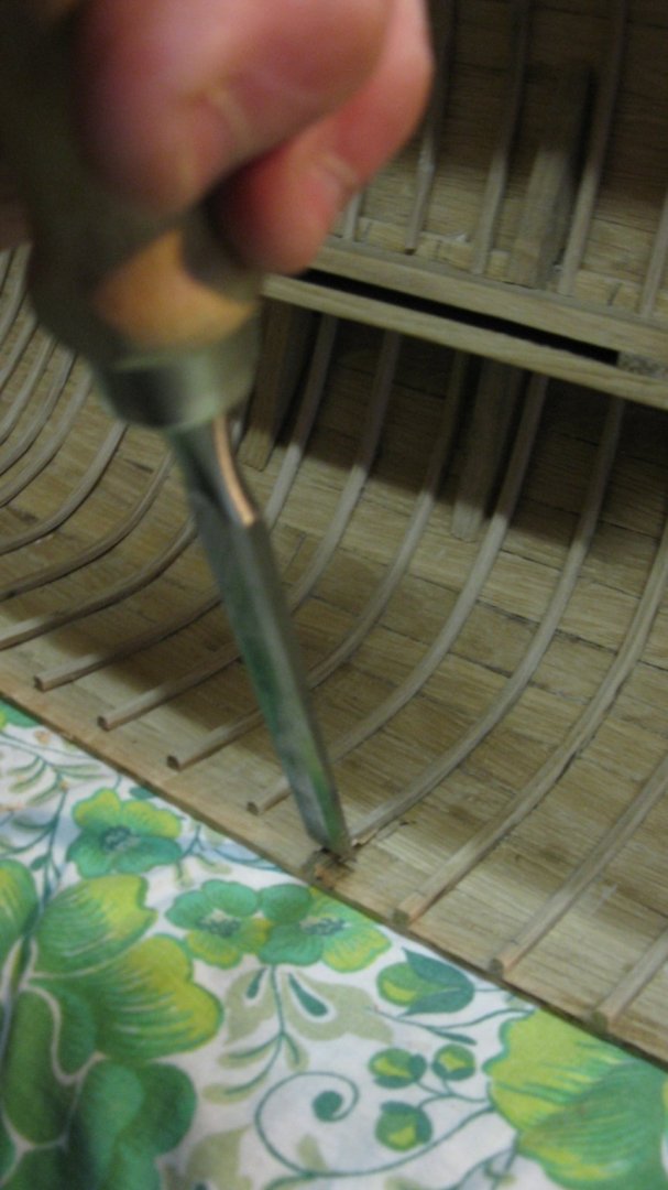
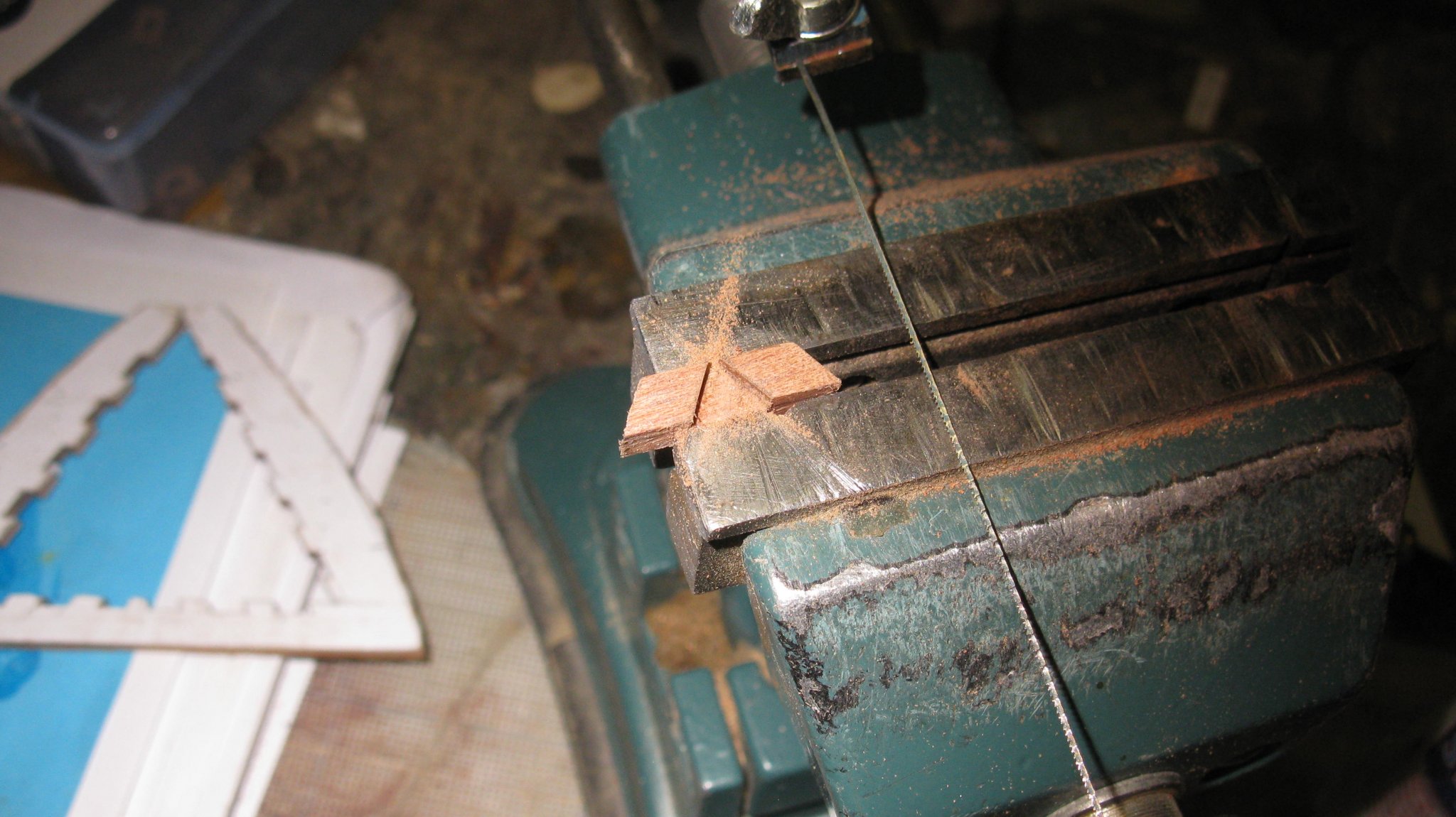
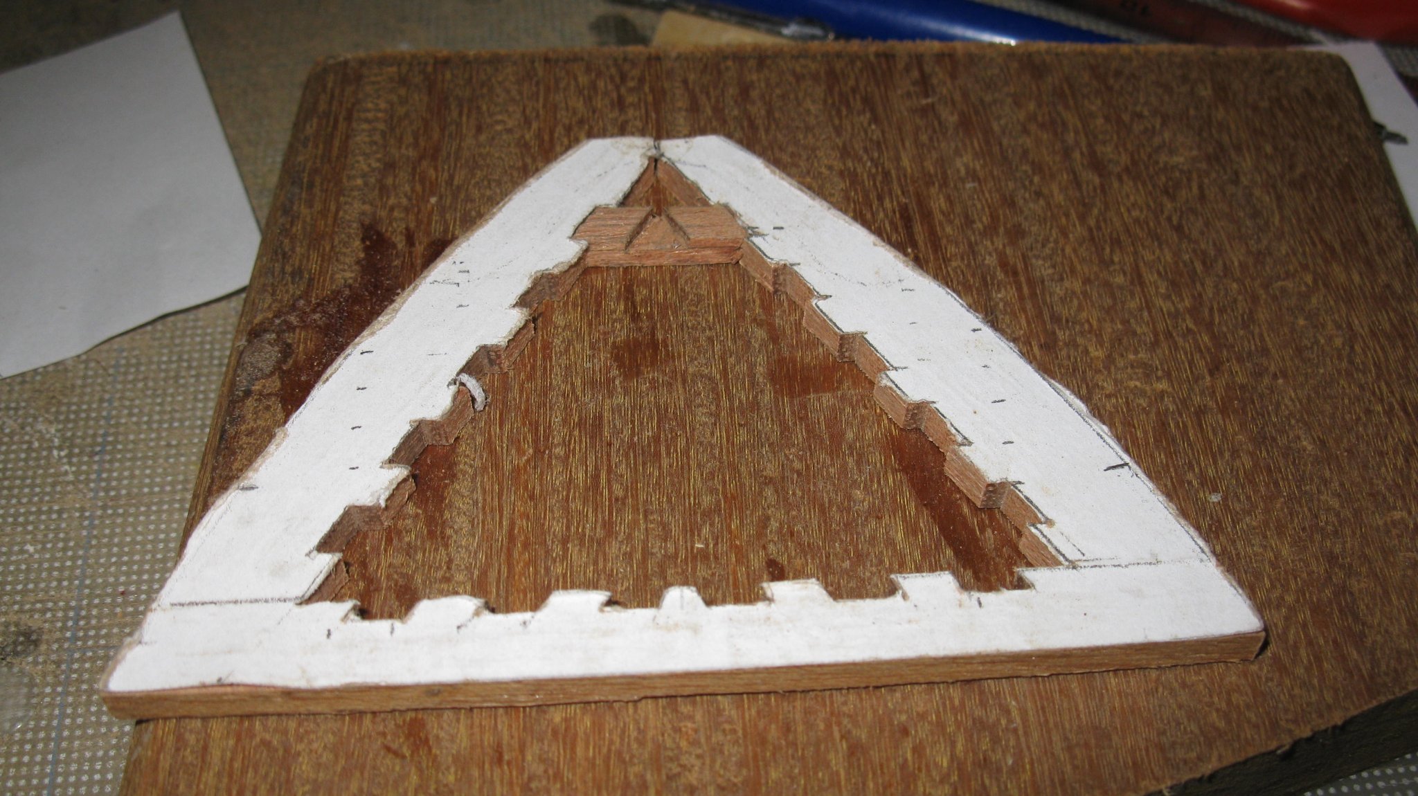
I use a bench vice as guide to saw out the notches in the inner side accurately. Poor photography, but it shows what I mean (I will have to follow a photography course at Gaetan Bordeleau😉).
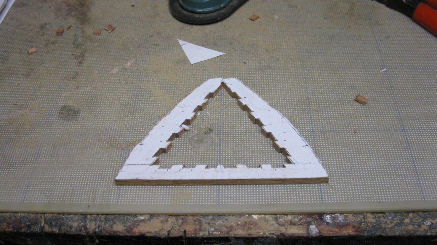
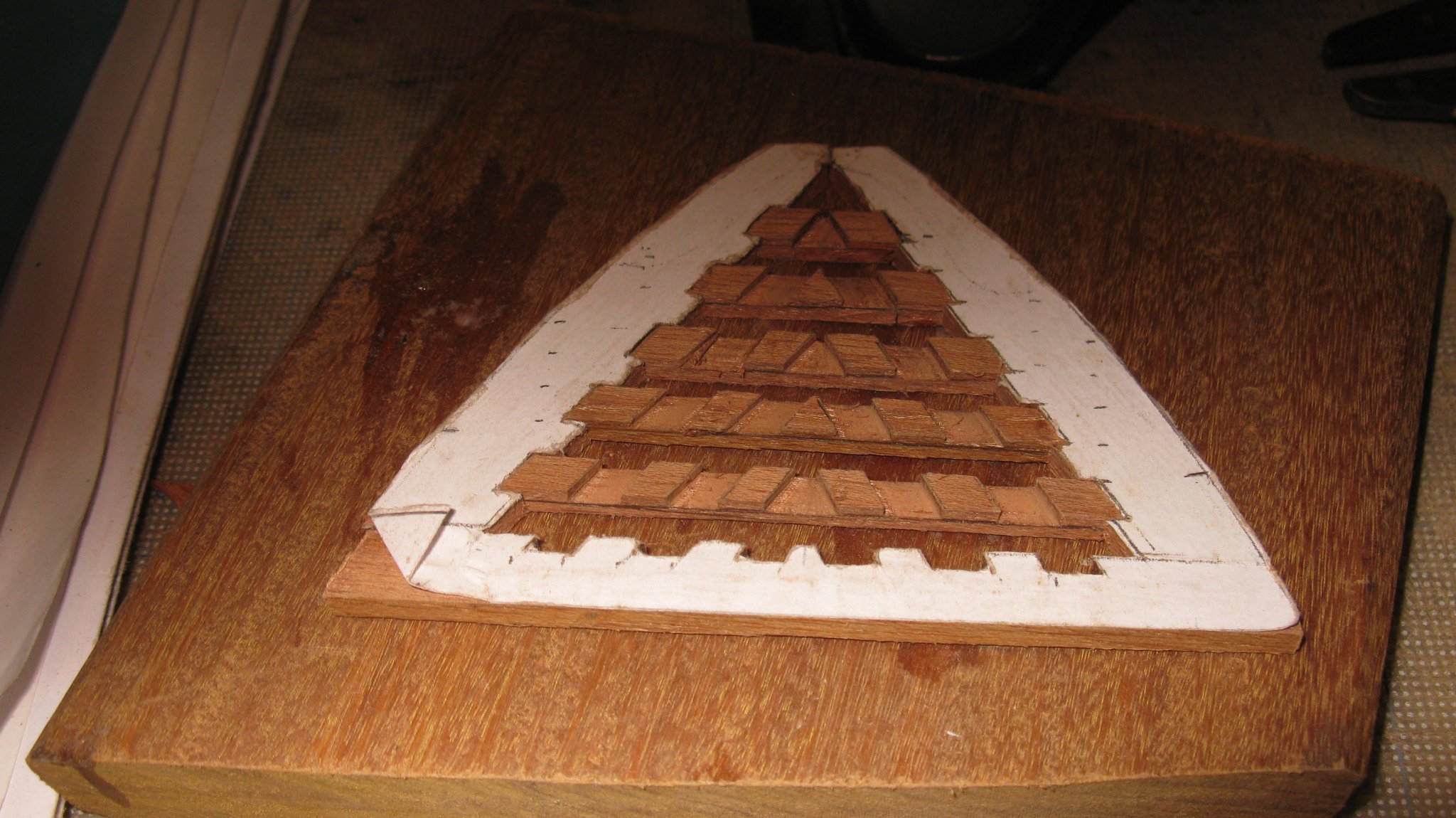
Sawing the cross slats ...

... and gluing them into the frame.


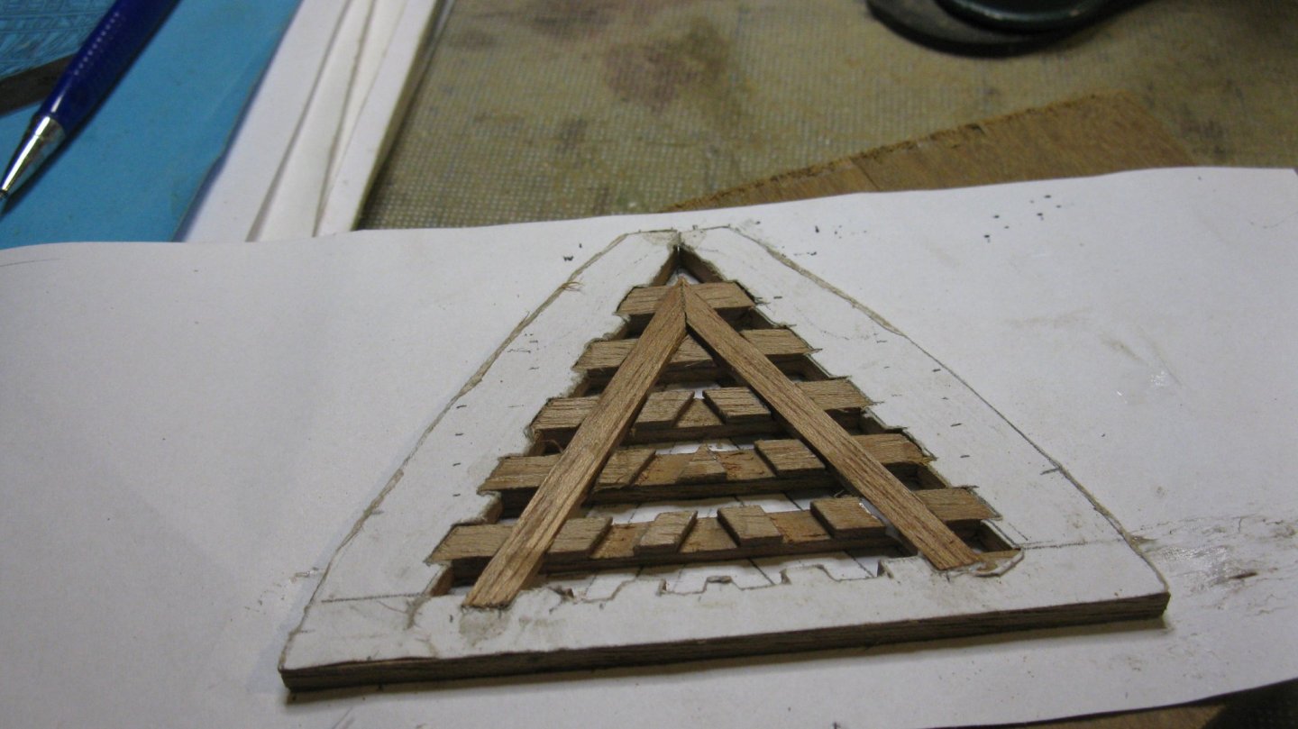
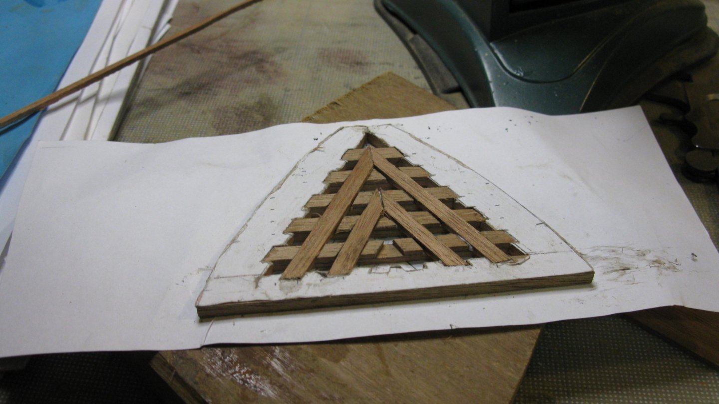
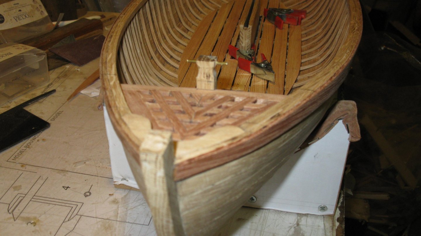
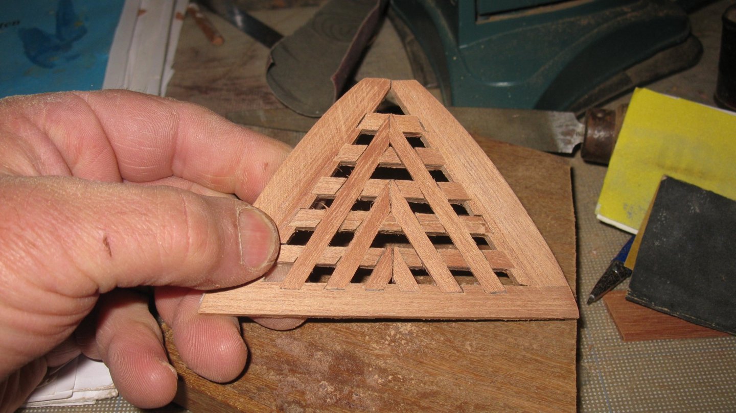
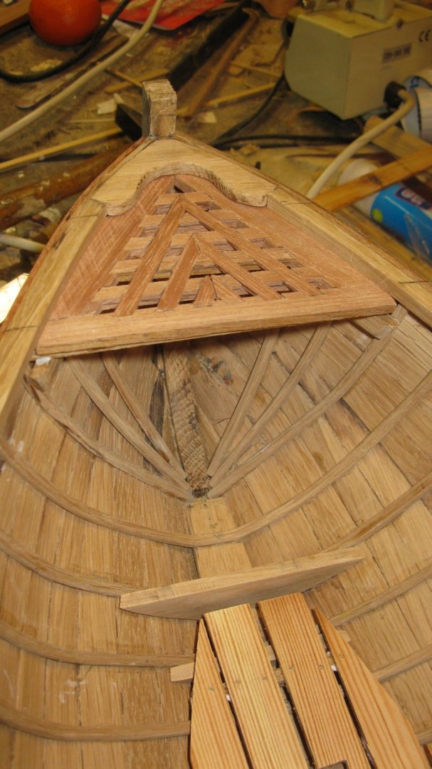
The grating:
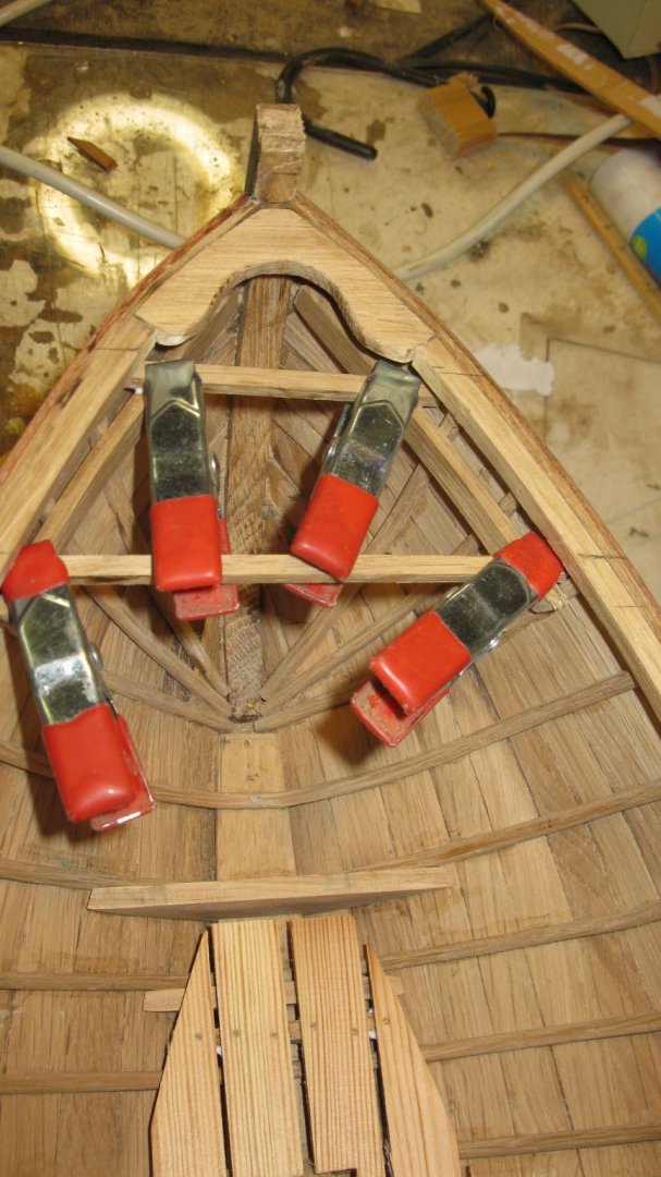
The carrying beams for the grating are laying on two short risings. Gluing them in. The temporally plank above each rising keeps it at the correct distance from the gunwale.
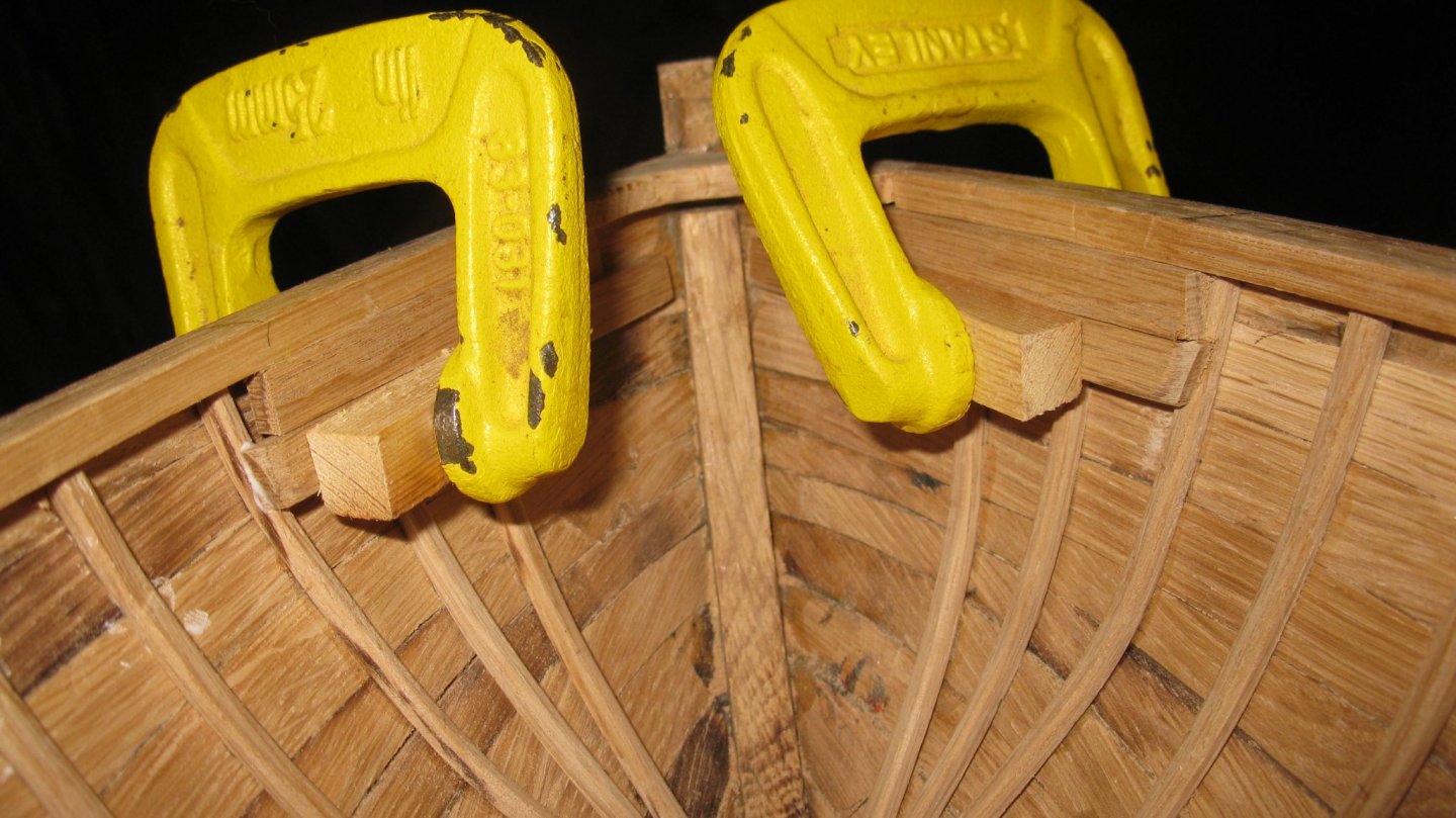
Gluing the beams.
Grating placed.
-
She is looking just as a real one, Paul.
-
On 10/14/2019 at 5:50 AM, michael mott said:
The model is looking great, Nice work on the ribs.
Michael
10 hours ago, KeithAug said:A very nice model particularly when considering how difficult oak is to work with at small scale. Well done.
Thank you very much for your comments Michael and Keith. As a follower of the work of you both I consider them as big complements.
-
-
-
-
1 hour ago, flying_dutchman2 said:
This is the most challenging part of building the Fluit. Once that is done, the rest of the planking will be easy to install.
Marcus
Marcus, I am convinced that many more challenging parts will follow.
- mtaylor, FriedClams and cog
-
3
-
-
Thank you very much for this explanation, Vaddoc.
I will finish this hull as it is , but I will redo it (the mold is made anyway) following your advices and will let you know how it worked. It will take some time because since August I started a new POF project and I am now sorting the pictures to start the log within a couple of weeks.
- FriedClams and mtaylor
-
2
-
Part 7. Finishing the hull
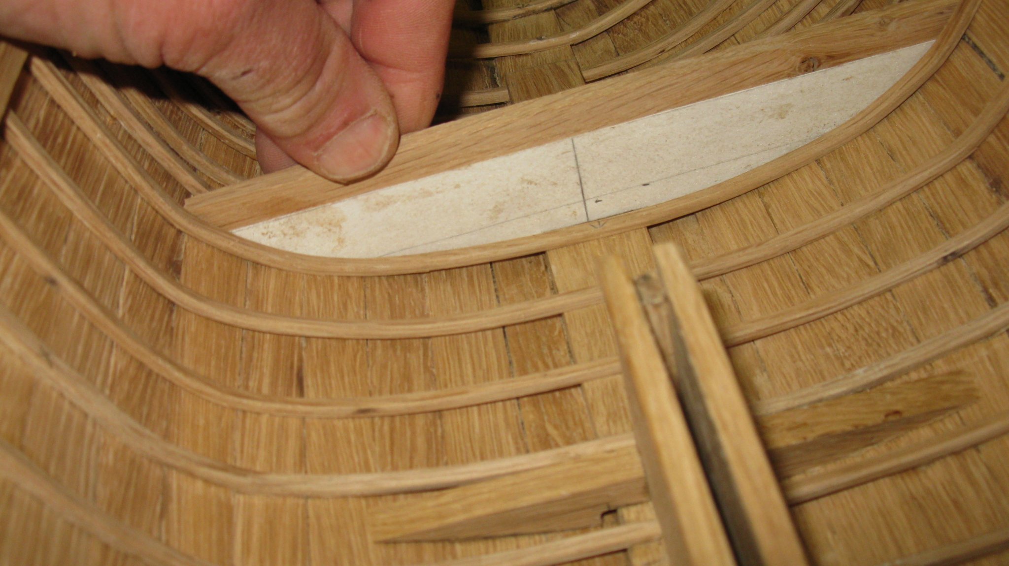
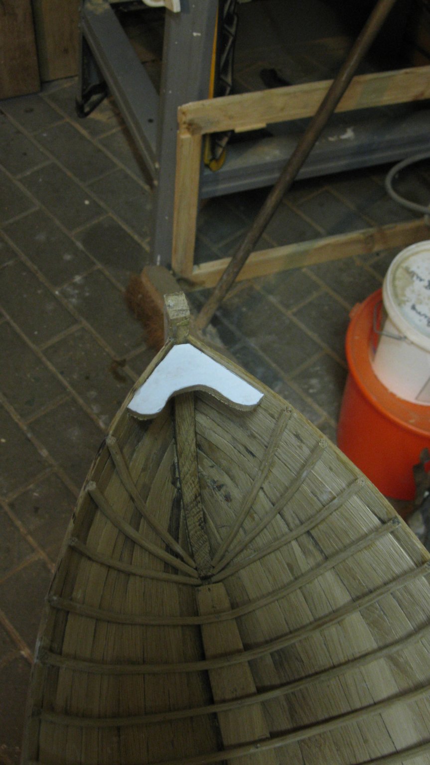
7.1. Breast hook, gunwales and rub rails
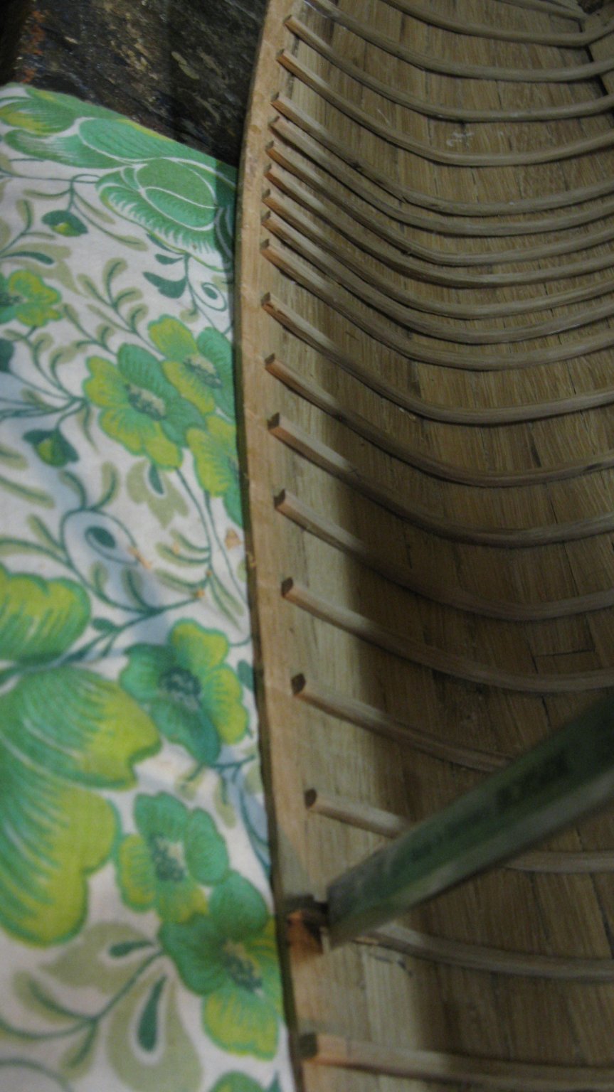
When all the frames are in place I shorten them all for 5mm to make space for the gunwale.

Taking over the shape of the bow on tracing paper to make a sawing template for the breast hook.
Sawing and fitting the breast hook.

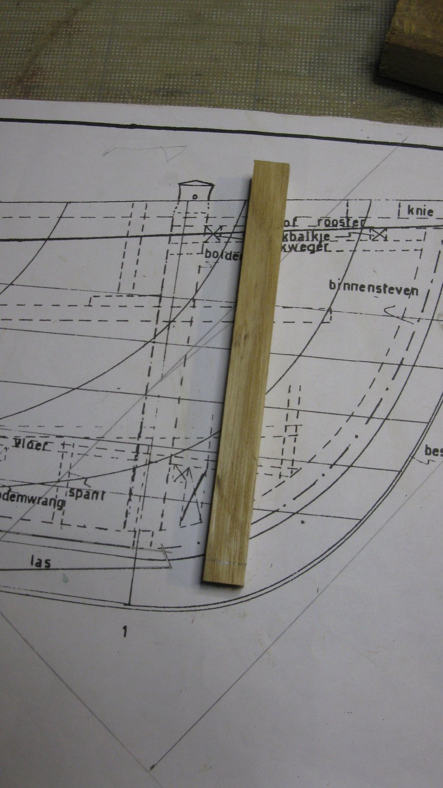
The gunwale is made of a 5x5mm oak bar.
Fitting the starboard gunwale.

Gluing gunwales and breast hook.

Without clamps
I plane 2 mahogany planks to a thickness of 2mm.to make the rub rails.

The two rub rails shaped...


... and glued

The rub rails:


Thank you to follow.
Thank you for the likes.
And thank you for the constructive comments.
Till next week!
-
On 10/5/2019 at 10:36 AM, Mirabell61 said:
beautiful job on the framing method Geert,
a nice light-weight hull, providing plenty of space for further fitting out to the inside of the shell......
Nils
I am glad you are liking my work, Nils.
On 10/5/2019 at 7:27 PM, mtbediz said:Excellent build. Very instructive, thank you.
Thank you for your comment, Mustafa.
On 10/6/2019 at 3:39 PM, vaddoc said:Lovely work Geert, just found the time to visit. I especially like the scale and the proper steam bending of the frames!
The second method of planking you followed is much more likely to produce accurate results. Could I make a few suggestions from my experience:
You can take the pattern of a plank in segments, one third first, then add the second etc, see photo bellow
Use thicker card so that it cannot be bent laterally. The cardboard in the photo is 2 mm (The planks were also 2 mm)
The garboard plank should reach as low at the stem as possible, so the rest of the planks are less cramped and lie more fair.
The shape of the planks, after the position in the frames is determined, need to somehow be faired.
Your suggestions are very much appreciated, Vaddock. I am an enthousiast follower of your 5-tonner log. Exceptional job you do there.
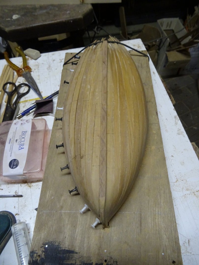
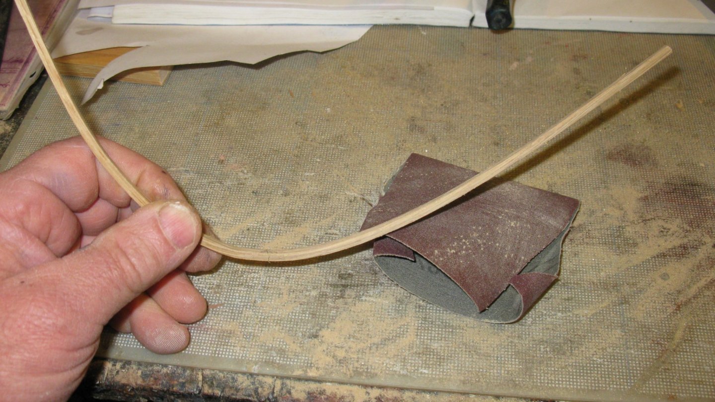
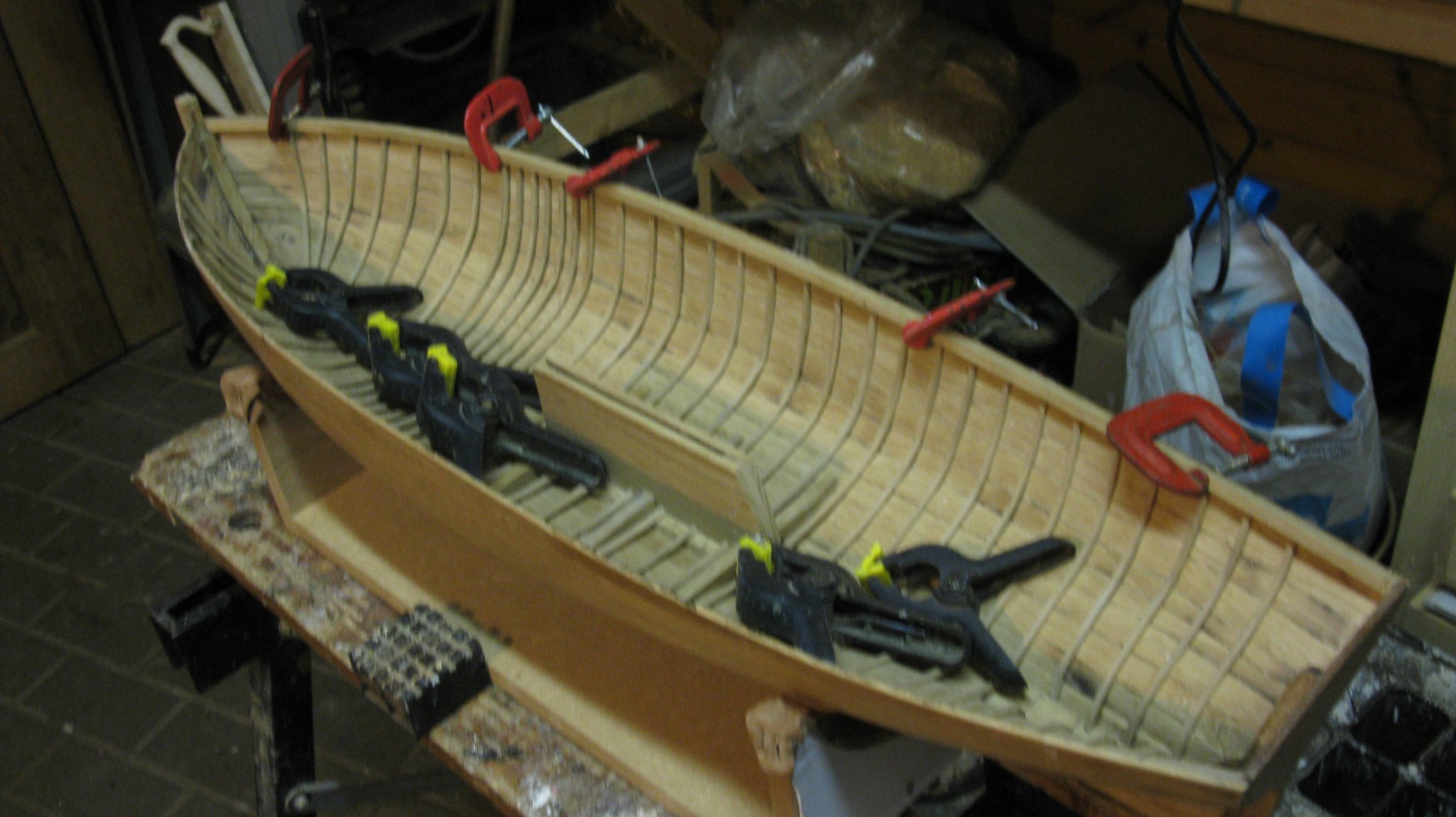
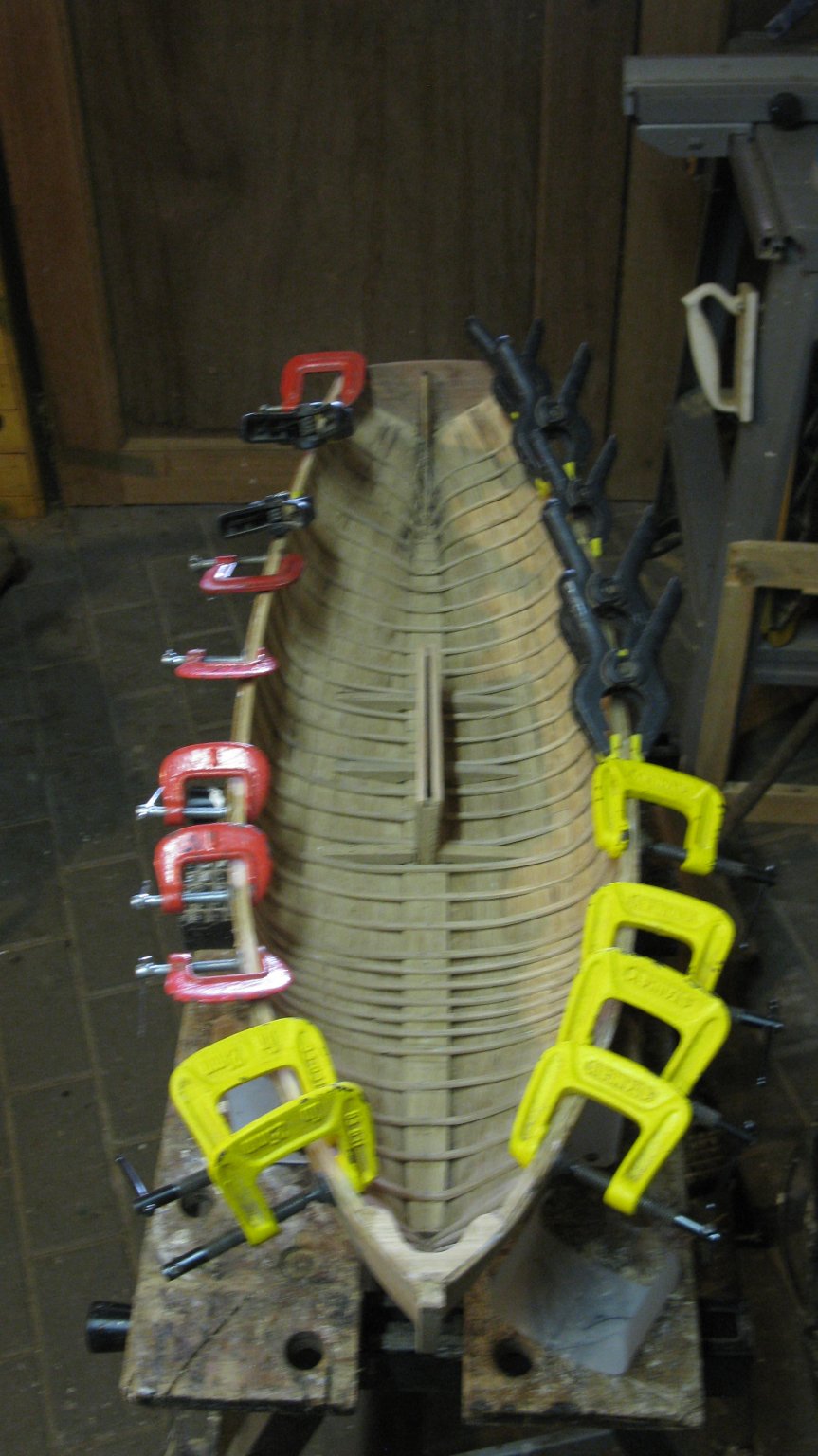
As a matter of fact, Pete (Peter Cane) drew my attention to the planking tutorials on the HGR site. This week I spent some time on experimenting with the method that Tony (Tkay11) used also for his chaloupe armée. This method prescribes tu use planks with only one tapered side and one straight side instead of fully lofted out planks. For my try-out I remake the work boat of my smack cross section, this time in a 1/10 scale. I build it on a spruce block model mold.
I am not convinced that it is really the method that I am searching for:
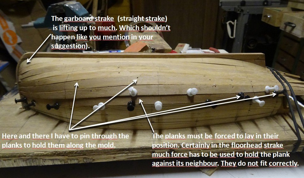
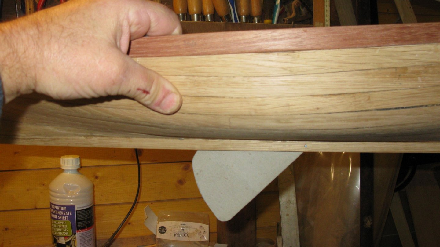
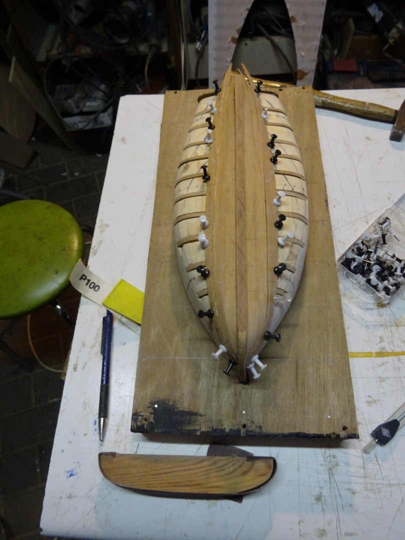
To make this answer I prematurely scraped an sanded a part of the hull to see what I still can make of this hull. Against my expectation the result is not as dramatic as I feared. Here some pictures. Port side is partly sanded, more sanding will still be needed. The pinholes in the strakes are filled by gluing a wood splinter in it.
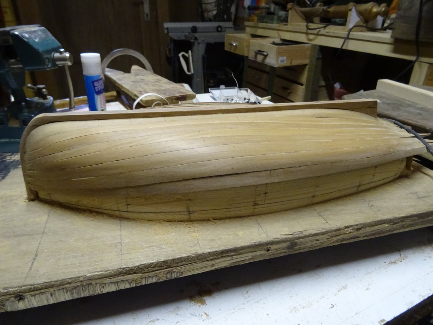
I will finish this hull. I am curious how it will look inside. Probably I will remake it another time, this time with lofted strakes and with templates in segments like you suggest. Maybe I should start a log of it on the forum.
On 10/6/2019 at 3:39 PM, vaddoc said:What glue did you use for the ribs?
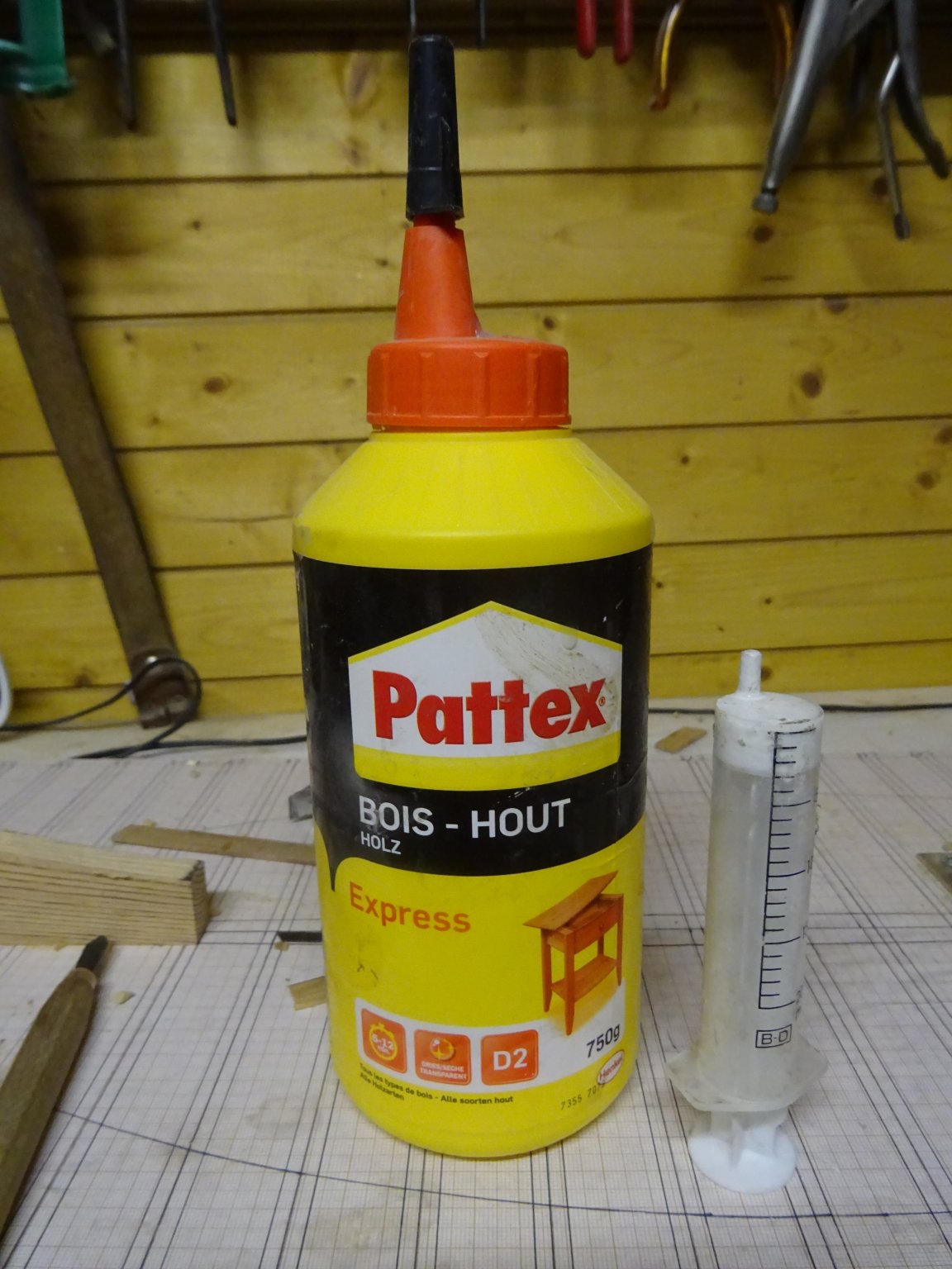
I use ordinary white wood glue. To apply it I often use a syringe.

-
-
Beautiful!
Nils, you take well care of your crew. I am sure they will like to work for you.
- Martin W, cog, FriedClams and 4 others
-
7
-
-
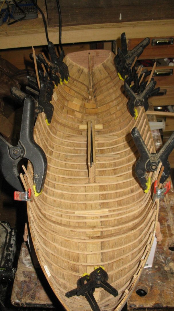
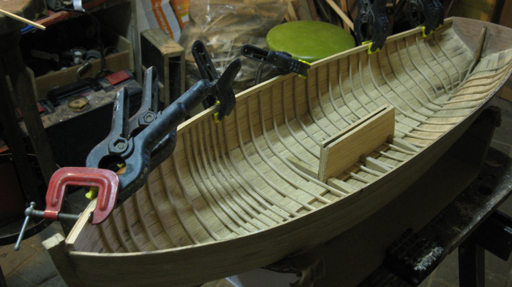
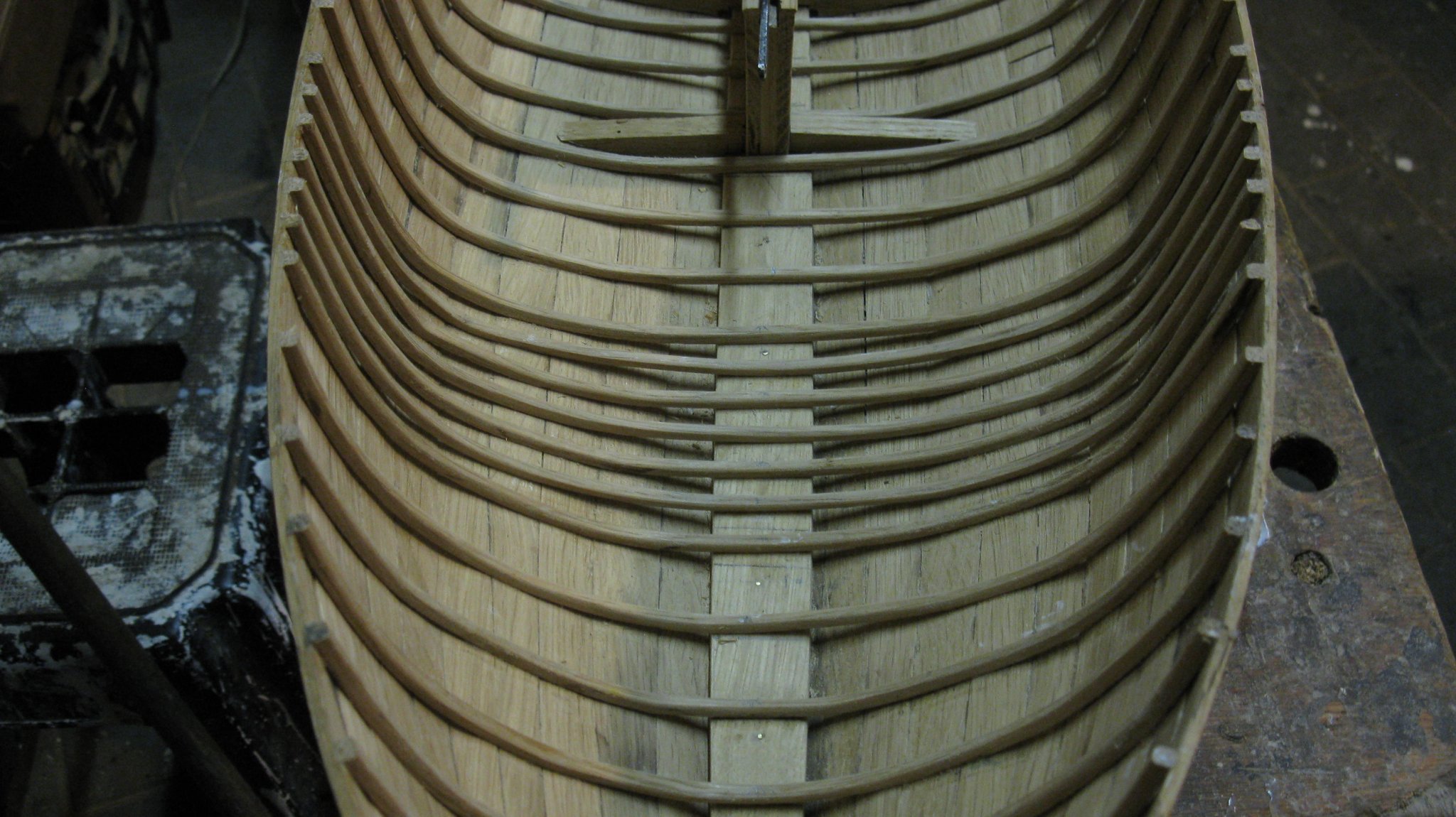
Part 6. The frames
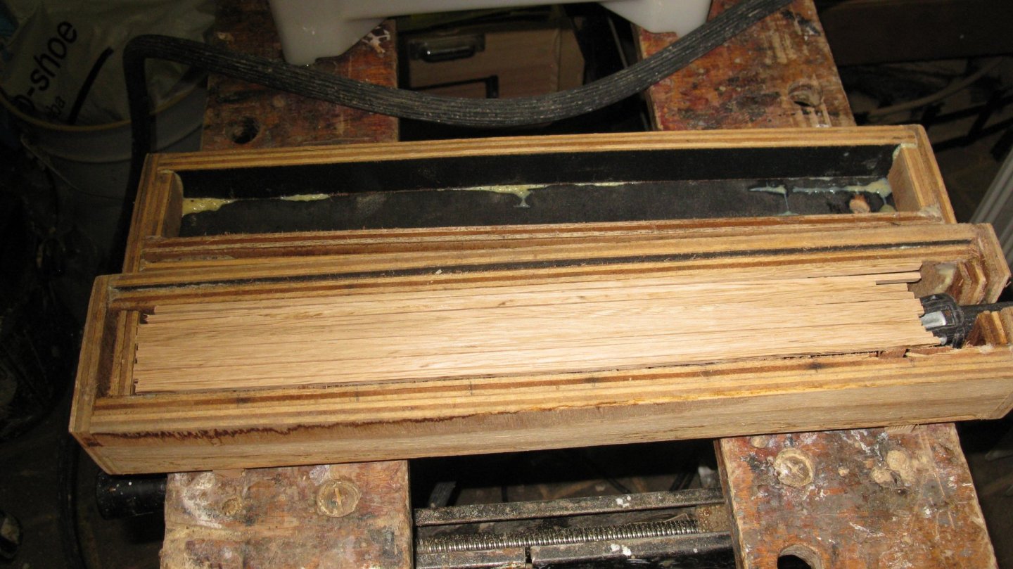
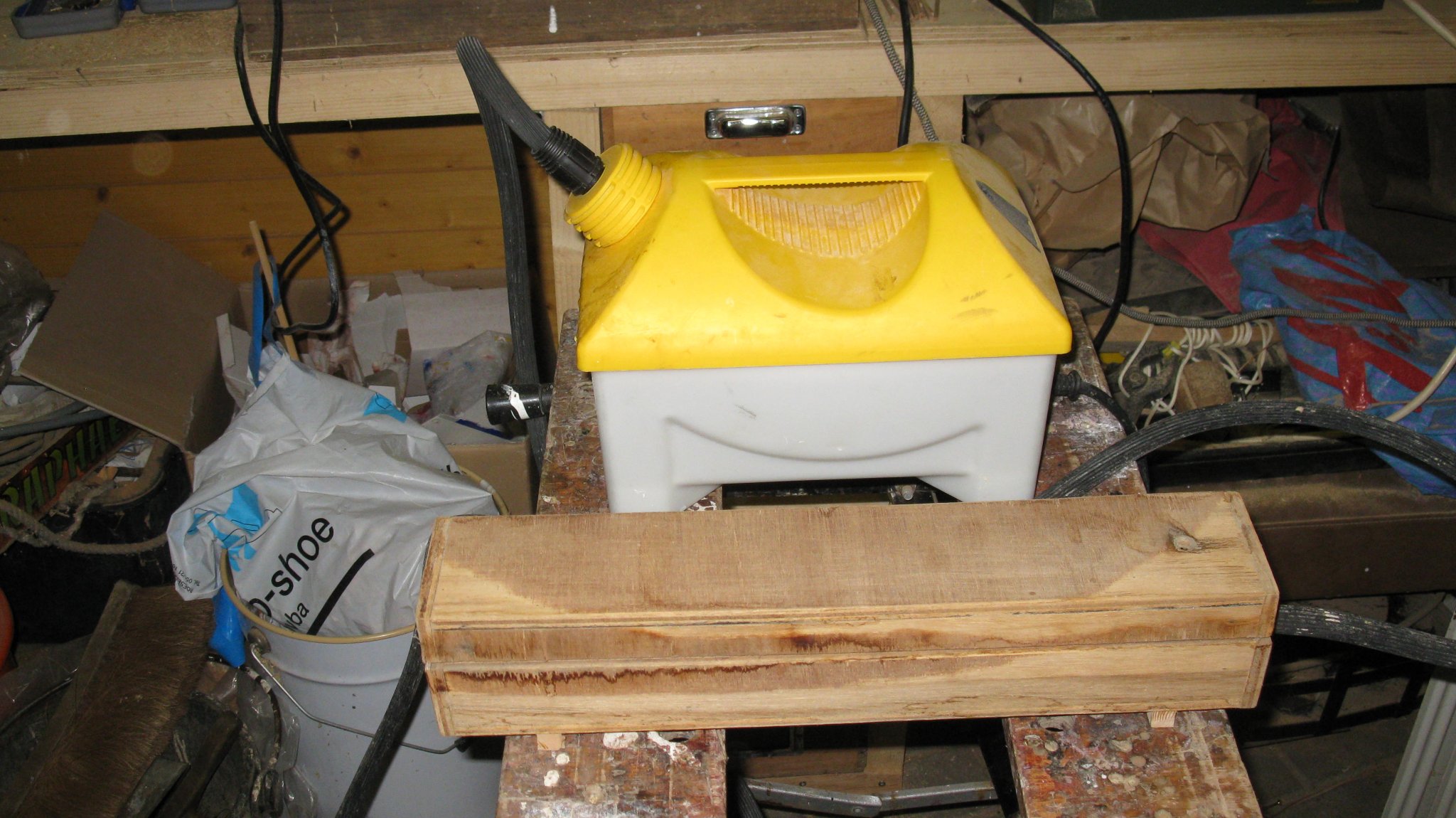
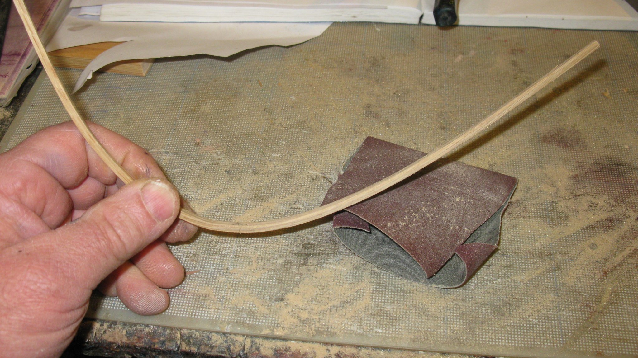
The frames in the model are 3x3 mm oak frames. To be able to bend them to the hull form I will have to steam them. I use the steam barrel of a wall paper steamer to produce the steam and connect it to a steam box made of plywood.

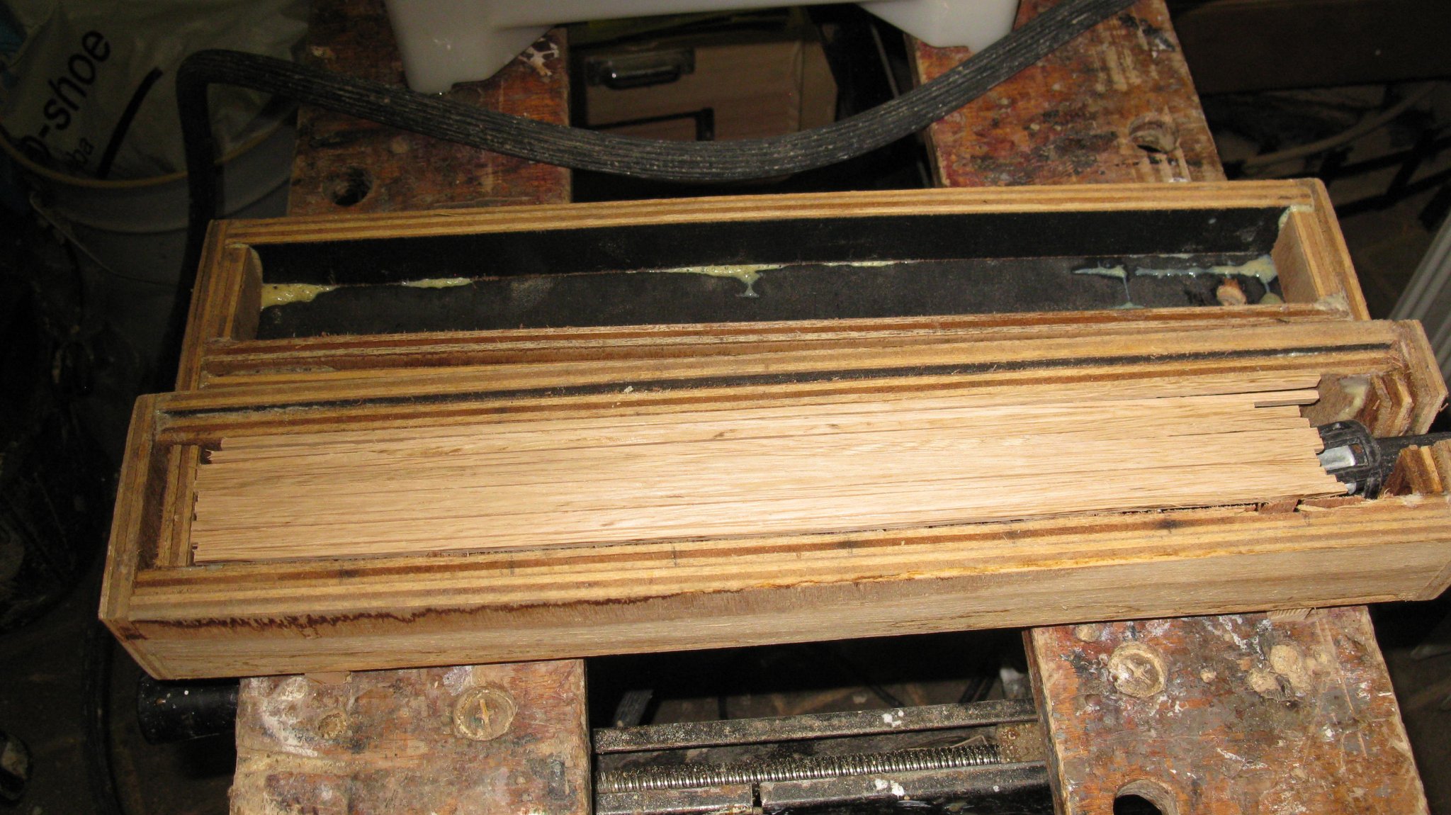
Inside of the steam box.
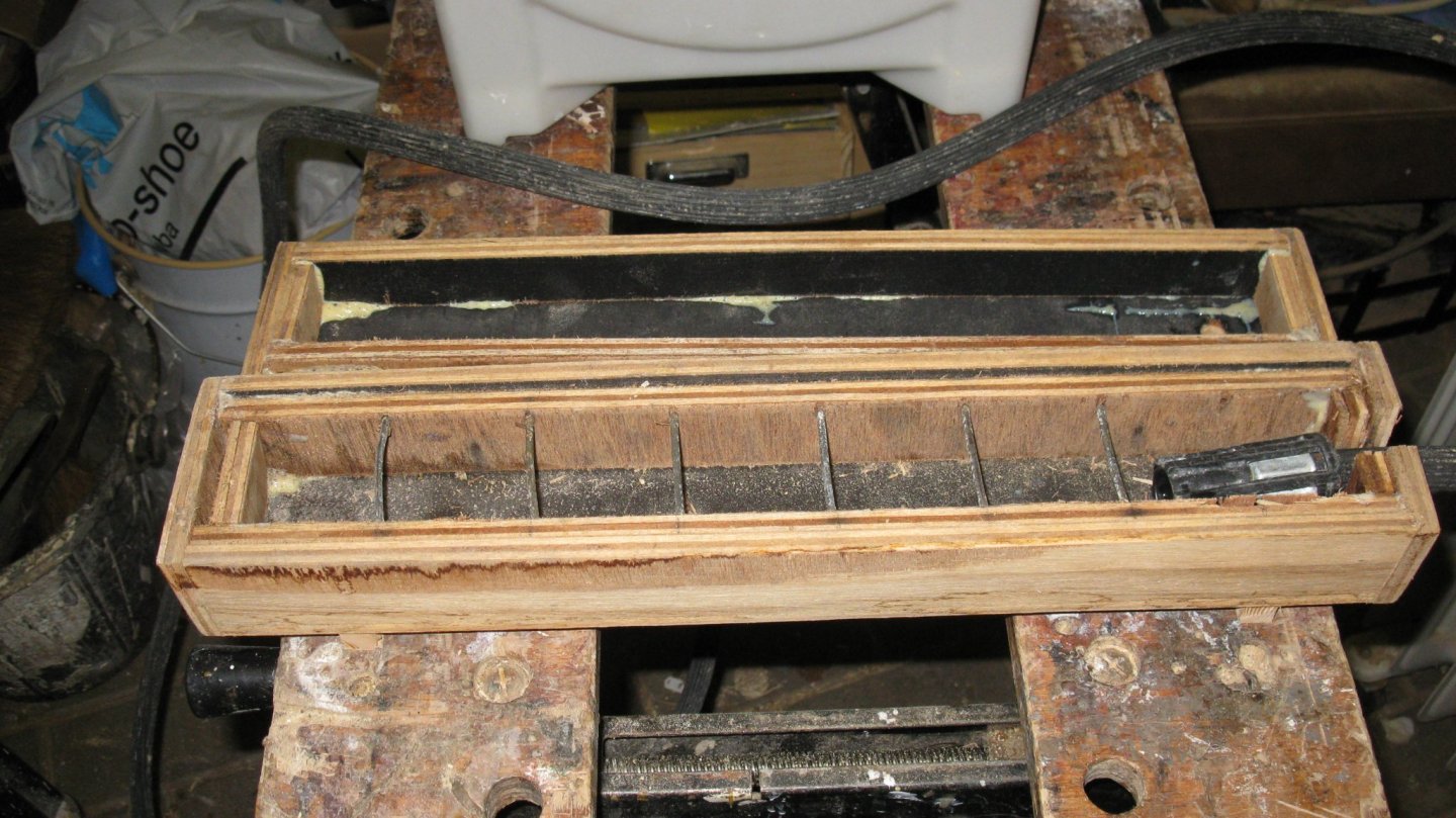
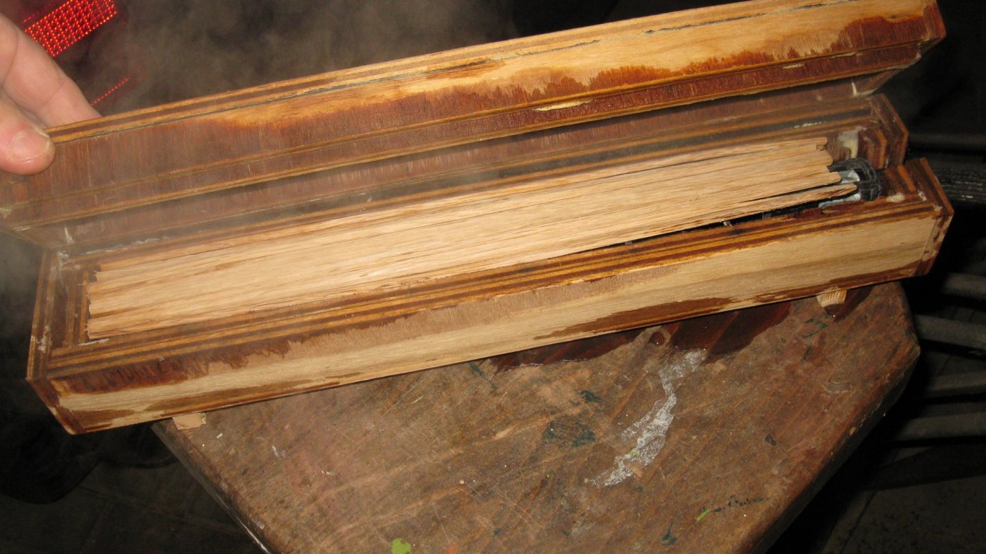
The frames are laid on the small metal cross bars to allow the steam moving all around the frames.
I place the steam box outside my workshop because of the escaping vapor.
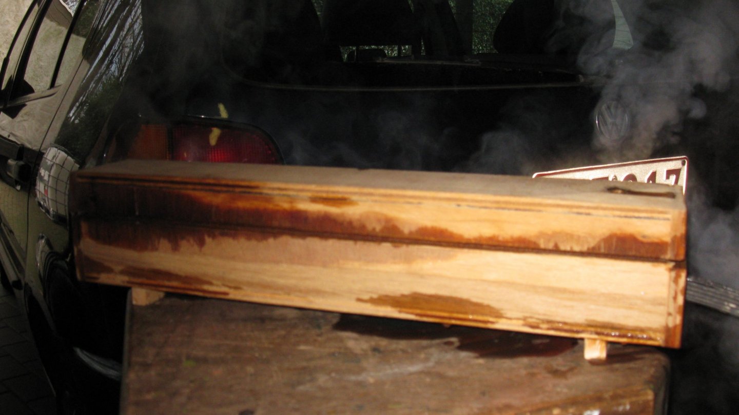
I leave the frames for at least 20 minutes in the steam.
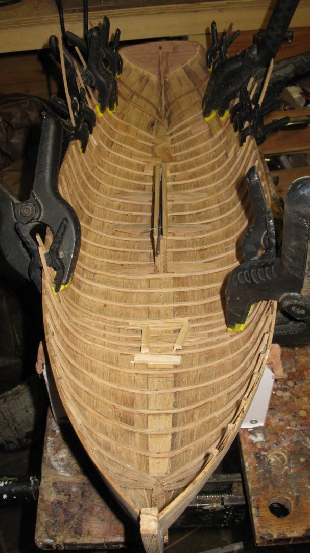
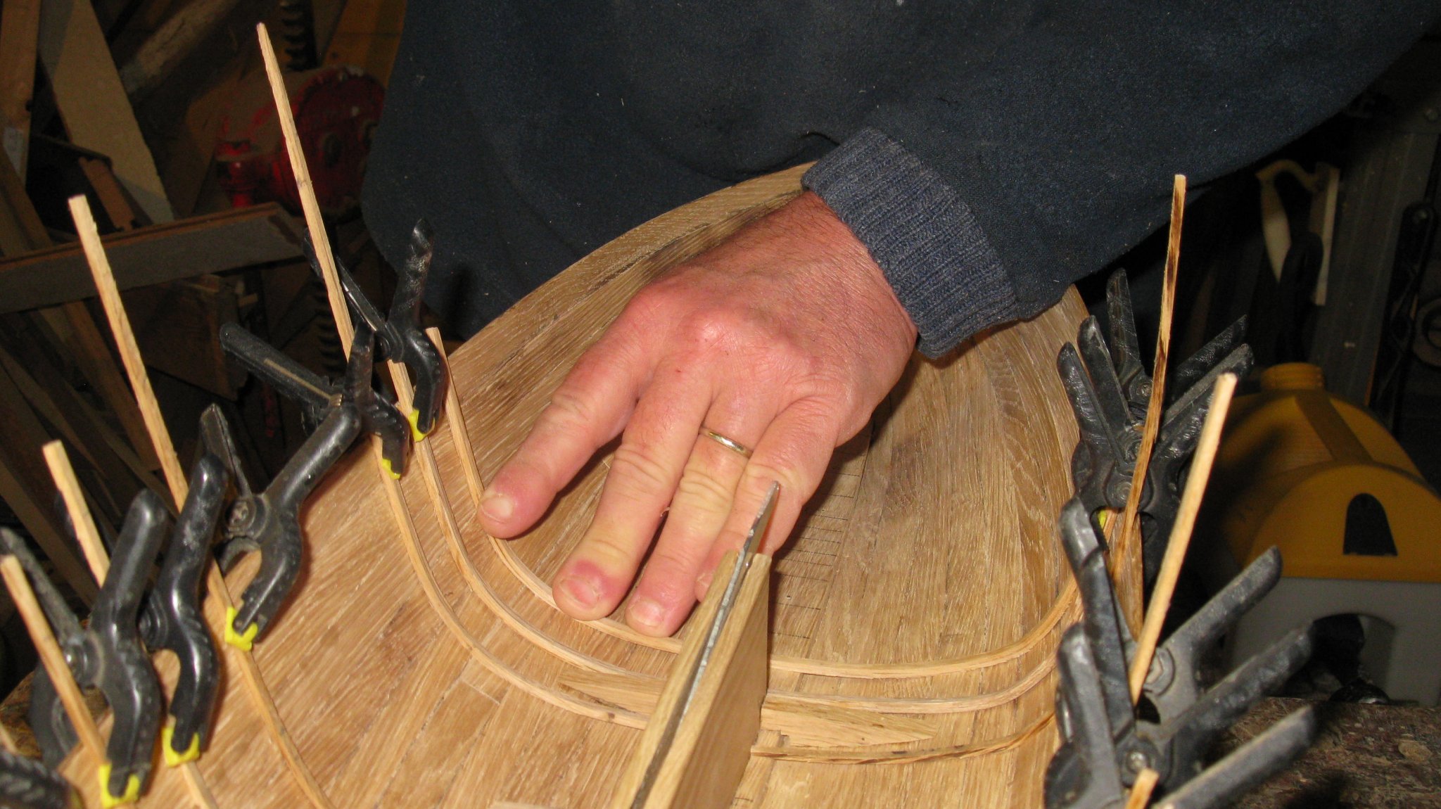
Then I press them gently into the hull. Sometimes one of them creaks but most of them go without problems.
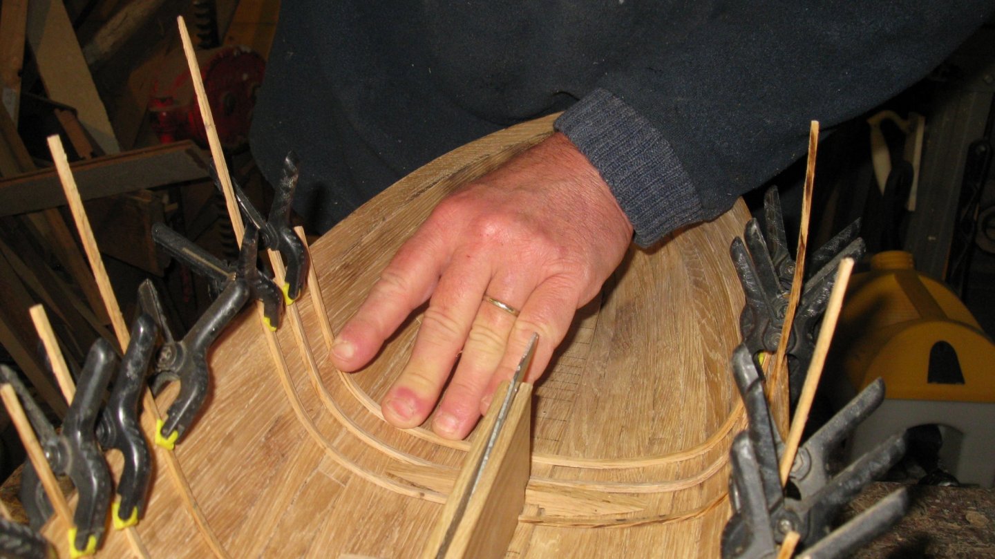
I use small wooden planks as spacers to glue the frames at equal intervals.
After a night drying, I take out the frames, sand them and glue them into place.
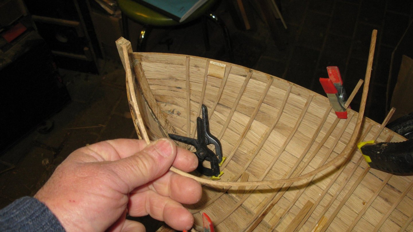

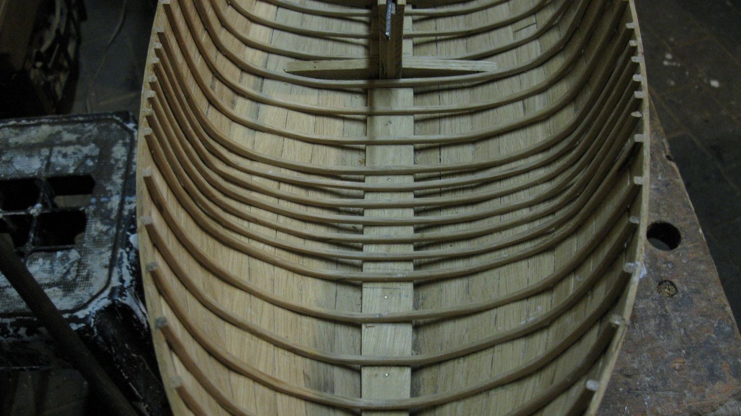
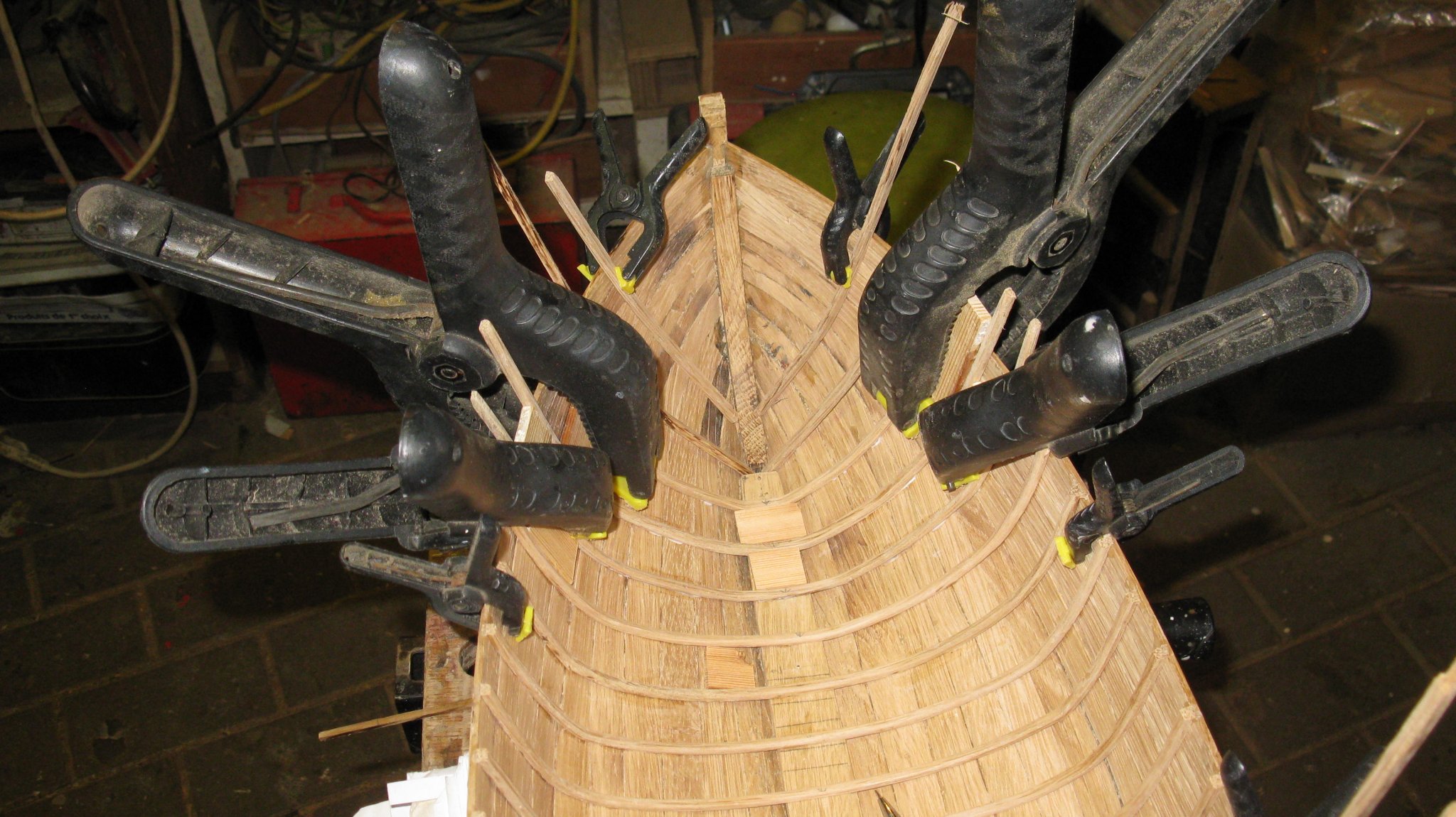
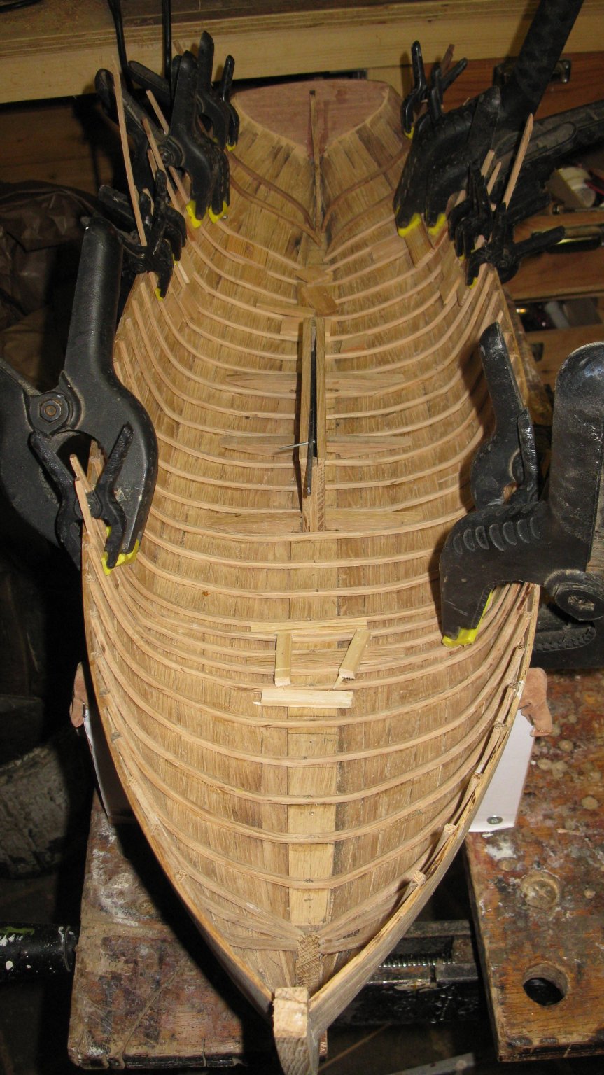
The placing of frames takes me several days.
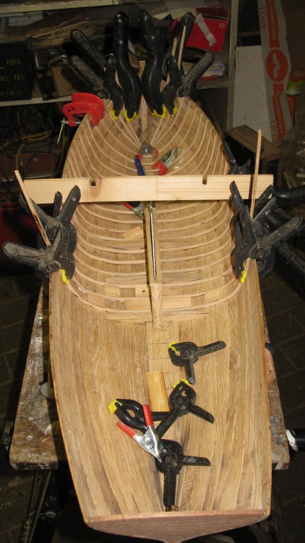
In the mast step area the frames are laying at half distance intervals.
Thank you to follow.
Thank you for the likes.
Till next week!
- GrandpaPhil, Baker, mtaylor and 15 others
-
18


New England Stonington Dragger by FriedClams - FINISHED - 1:48 - POB
in - Build logs for subjects built 1901 - Present Day
Posted
Gary, I agree with all previous comments.
The hull looks remarkably clean compared to the deck and the superstructure. Will you age it as well?