


G.L.
-
Posts
1,553 -
Joined
-
Last visited
Content Type
Profiles
Forums
Gallery
Events
Posts posted by G.L.
-
-
-
7 hours ago, Peter Cane said:
It is absolutely okay to disagree and I am really pleased you do.
Hearing all points of view opens up the mind to different concepts and solutions and creates interest.
My solution is but only one idea.
Pete,
This time I fully agree with you😄.
As long we express our point of view honestly in a polite way this forum remains a valuable learning school for us all.
- Martin W, Keith Black, mtaylor and 3 others
-
 6
6
-
Thank you for the video, Vaddoc. I am looking to improve my rope producing as well and certainly found some good ideas in you demo.
- mtaylor and FriedClams
-
2
-
I do not quite agree with Peter. I suppose that you prefer to use self-made portholes rather than bought ones, Nils. Brings me to my question: Did you cast yourself the portholes?
- Martin W, mtaylor, popeye the sailor and 1 other
-
4
-
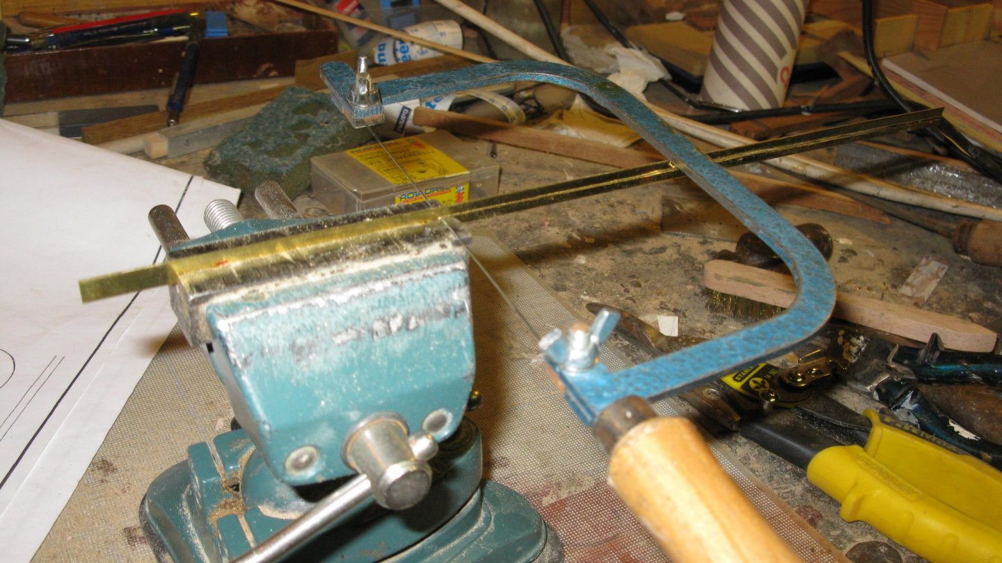
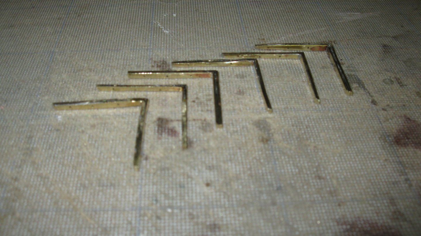
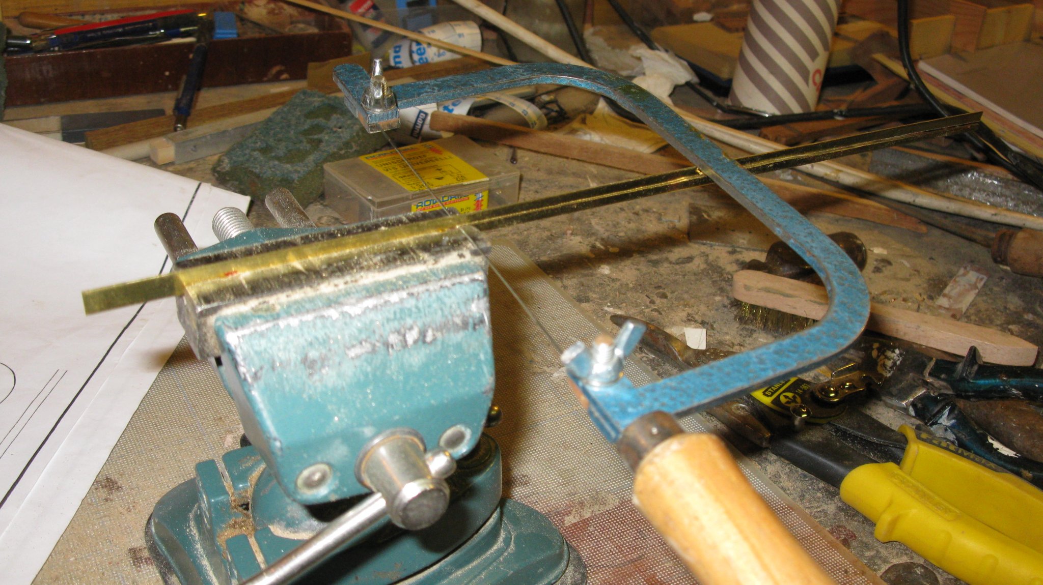
The center board case is supported by six metal knees, three at each side.
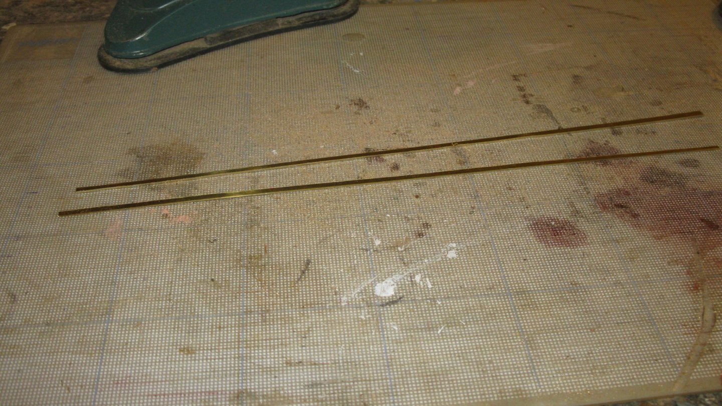
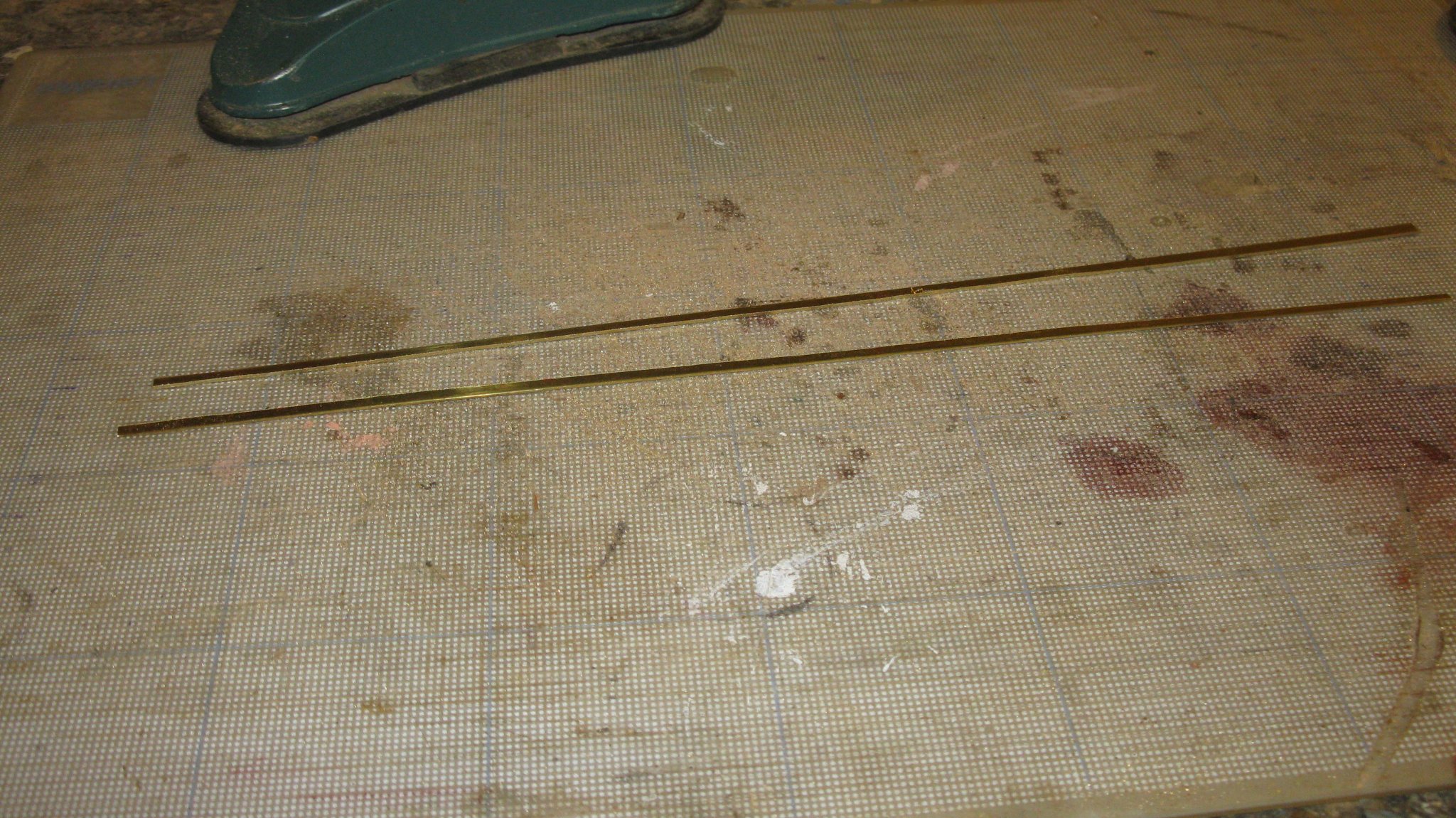
The knees must be 2.5 mm thick on the model. I do not have such a thick brass plate, so I will laminate the knees. First I saw some brass strips of 0.8 mm thickness.
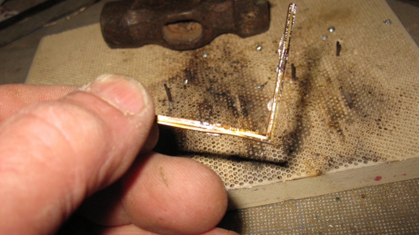
I forgot to make a picture of the first step: First I folded one strip in a right angle, L-shaped with two equal legs. Then I covered the two legs of the angle at both sides with a tinned strip. I try to show it schematically:

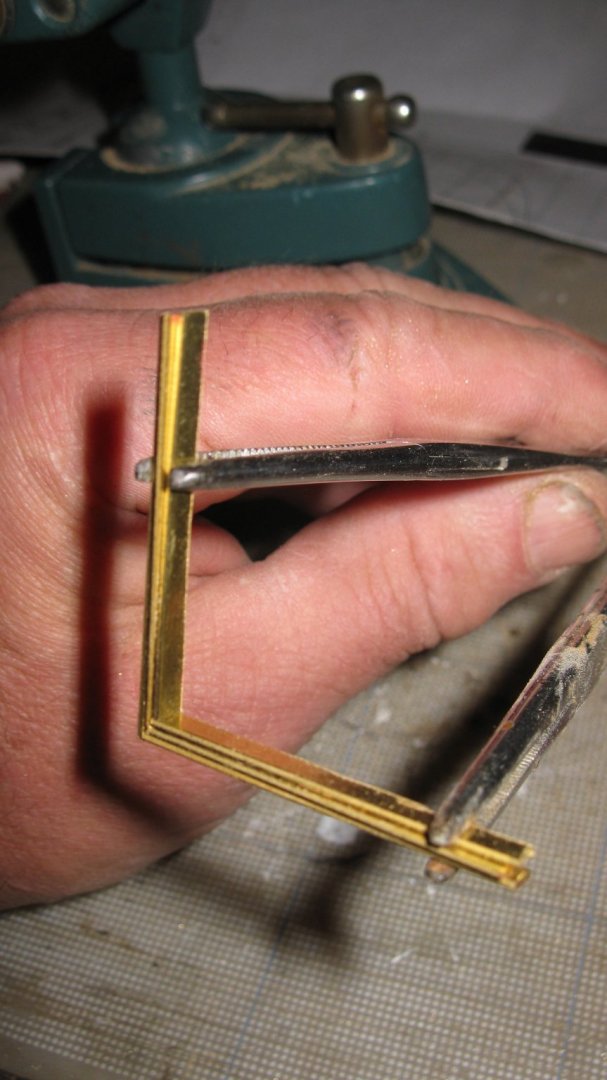
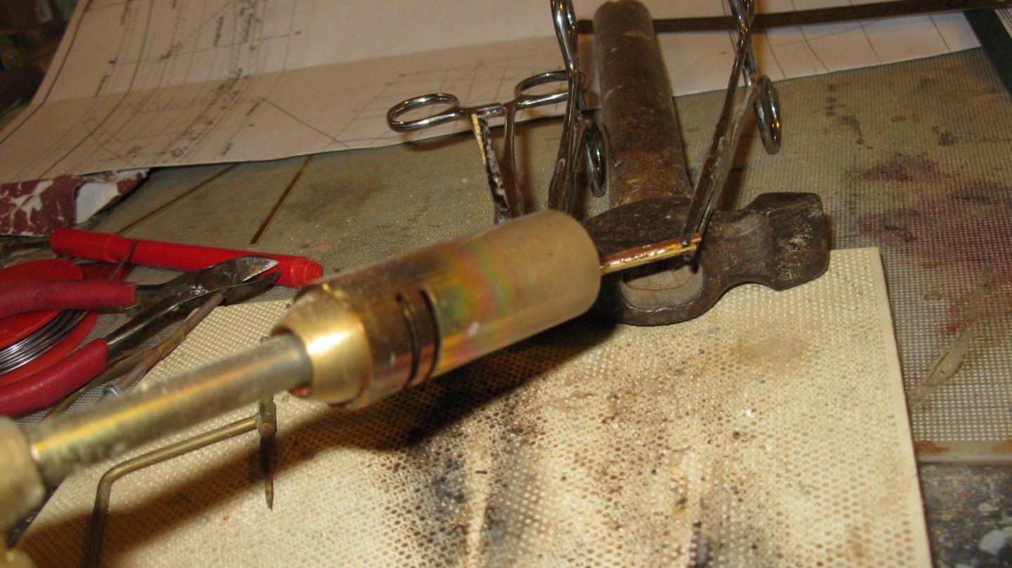
Then I solder the whole knee together by heating it with a gas burner.
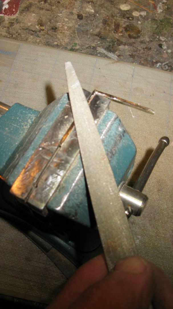
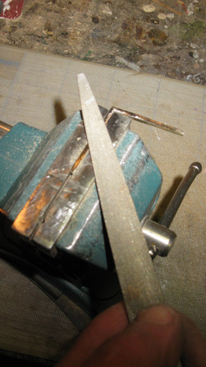
Filing the knees.
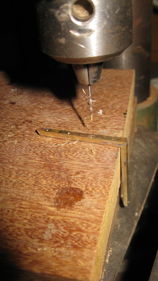
Drilling the nail holes.
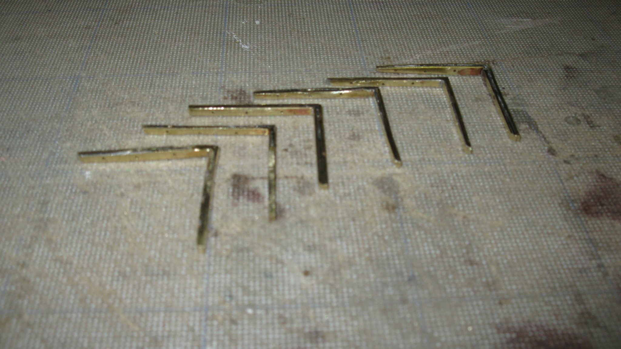
The six knees for the center board case.
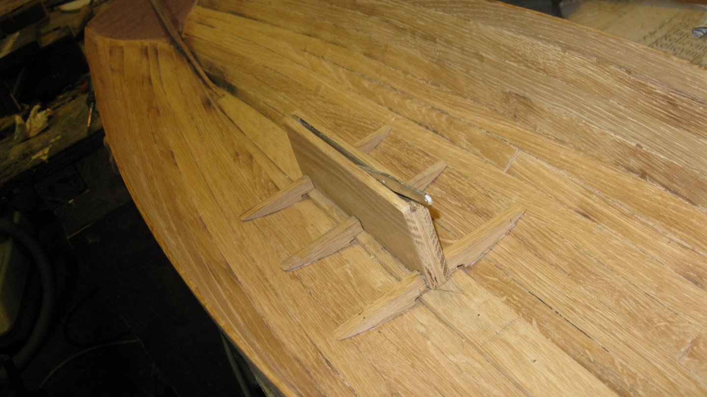
The metal knees stand on wooden floors. Between the keelson and the floor piece there is a small gap for the smooth flow of bilge water.
Thank you to follow.
Thank you for the likes.
And thank you for the constructive comments.
Till next week!
- wefalck, GrandpaPhil, SJSoane and 11 others
-
14
-
-
Congratulations, a beautiful little girl!
- Keith Black, KeithAug and mtaylor
-
3
-
It looks like you are on the right track.
- mtaylor, Nirvana and svein erik
-
3
-
4 hours ago, AlexBaranov said:
Thank. Vintage is generally a copy of an old thing with traces of exploitation and time. I copy the exterior of old museum models of the appropriate style. But without traces of exploitation. The new fashion "torn pants with holes" someone believes that this is vintage. I argue that this is simply worn clothing characteristic of the poor or low strata of society. This is not vintage but a substitute for concepts. Vintage is primarily a kind of noble antiques antiquity.
Alex, I agree.
-
3 hours ago, AlexBaranov said:
The hull of the ship is made of individual parts cut on a CNC milling machine. Alder wood. Then the body is assembled on glue and fastened with beams and velvet. I did not take photos of a very long and monotonous milling process.
Thank you for your answer Alex. That is probably what you mean by 'using technology and vintage style' in your first post.
It looks very, very nice.
-
Alex,
A beautiful hull!
I am curious how you did build the hull. It doesn't look like a POF or POB built hull, more like a hollow block model. Do you have pictures of the making process of it?
- aviaamator and mtaylor
-
2
-
On 9/21/2019 at 10:04 AM, Ab Hoving said:
Beautifully executed!
Thank you Ab, your complement means a lot to me.
On 9/21/2019 at 10:53 AM, Peter Cane said:I think you have done a wonderful job.
Planking a hull is extremely difficult and I echo what you say about having respect for the old ship builders.
They were artists in their own right.
Love the centre board.
Pete
Planking on a 1/10 scale is indeed not easy. I would like to master the skill so I believe that one of my next projects will be a simpel vessel like a rowing boat on a 1/10 scale to further qualify myself.
Thank you for your comment Pete.
8 hours ago, Backer said:Beautiful work !
Thank you Patrick. Just lik you with the Golden Hind, I do my best to improve.
-
-
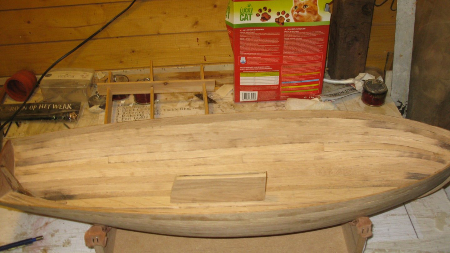
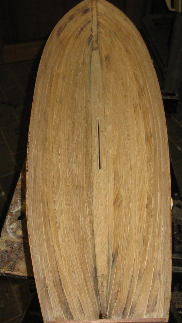
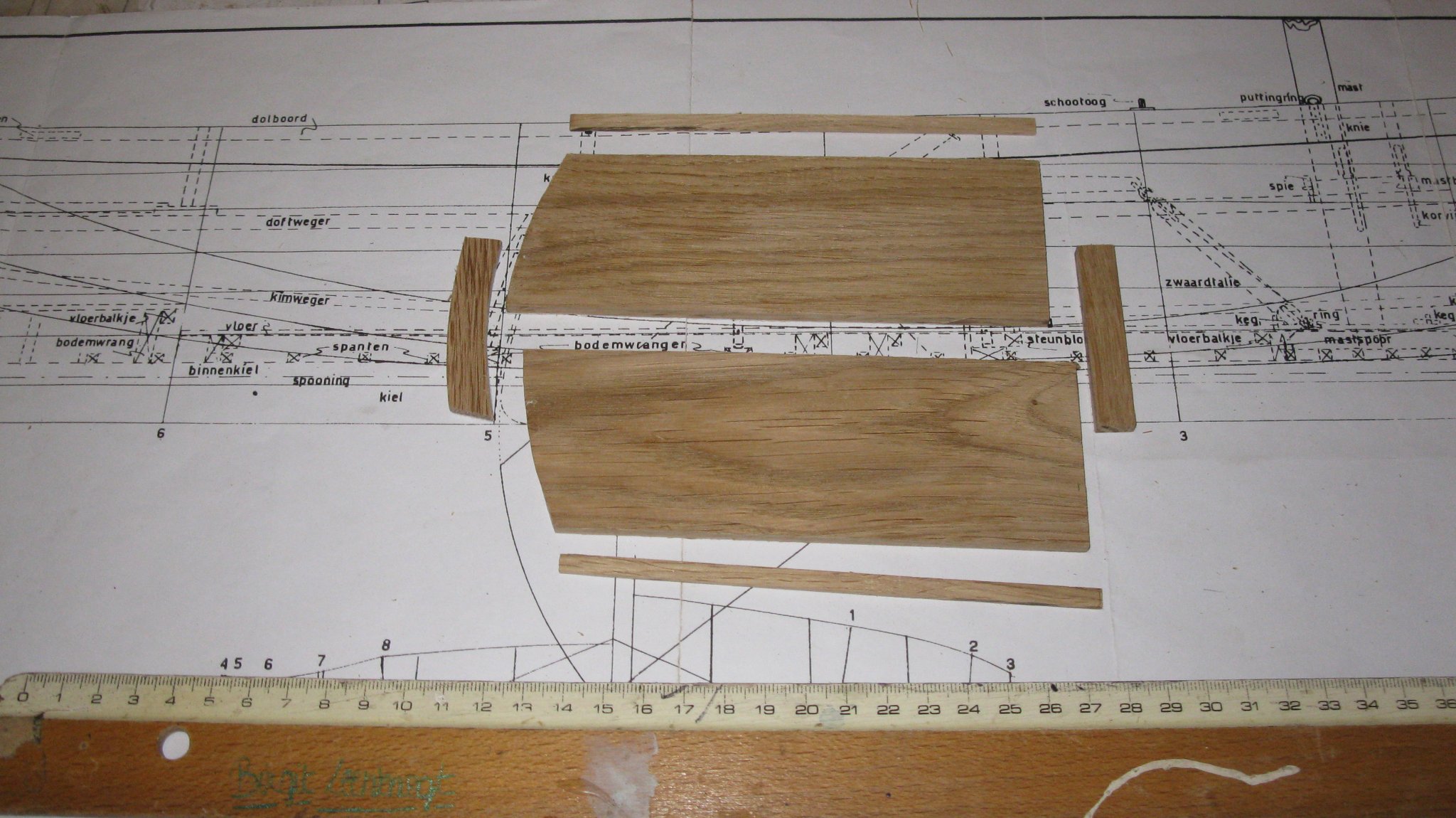
Part 5: The center board case and center board.
Next thing is making the center board case. Here you see the different parts.
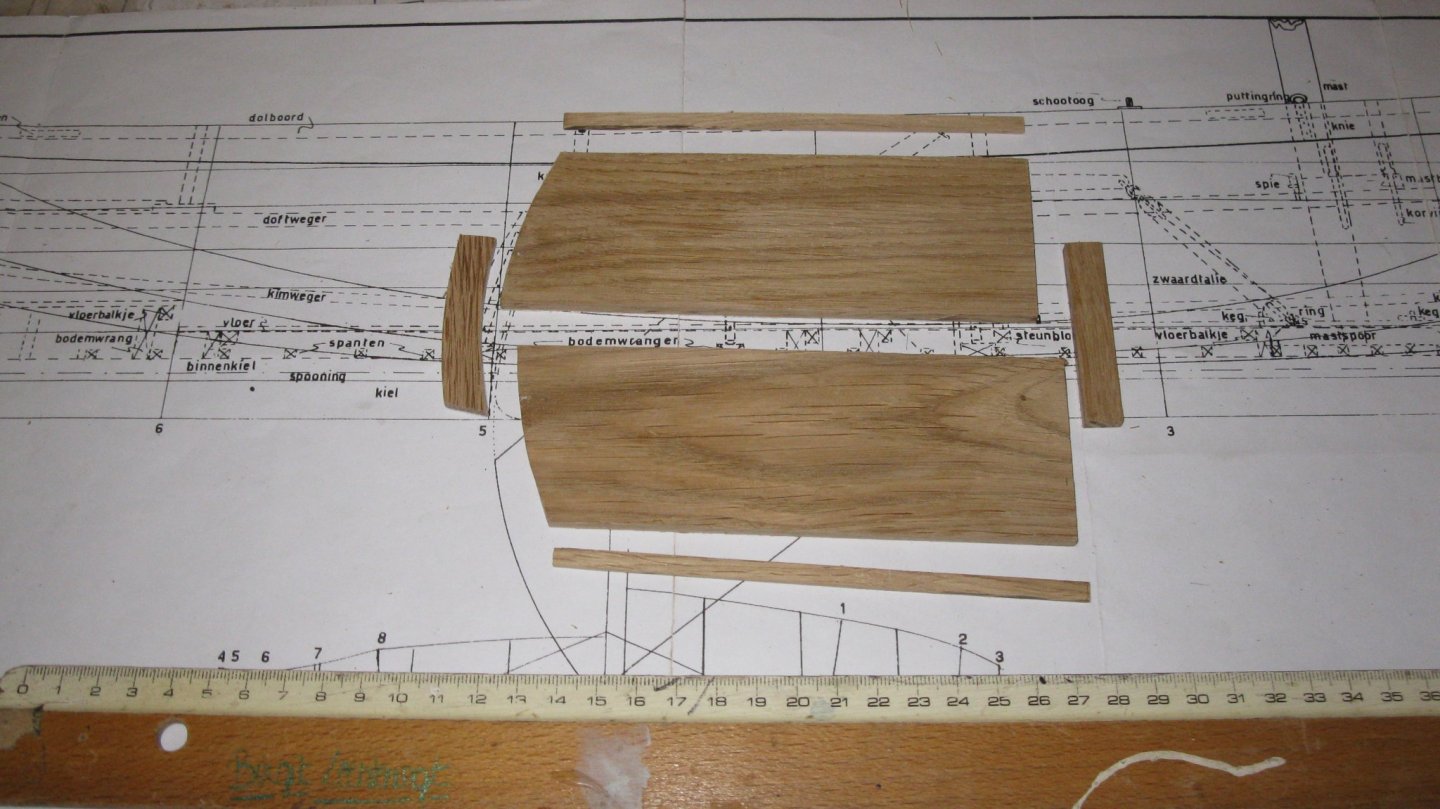
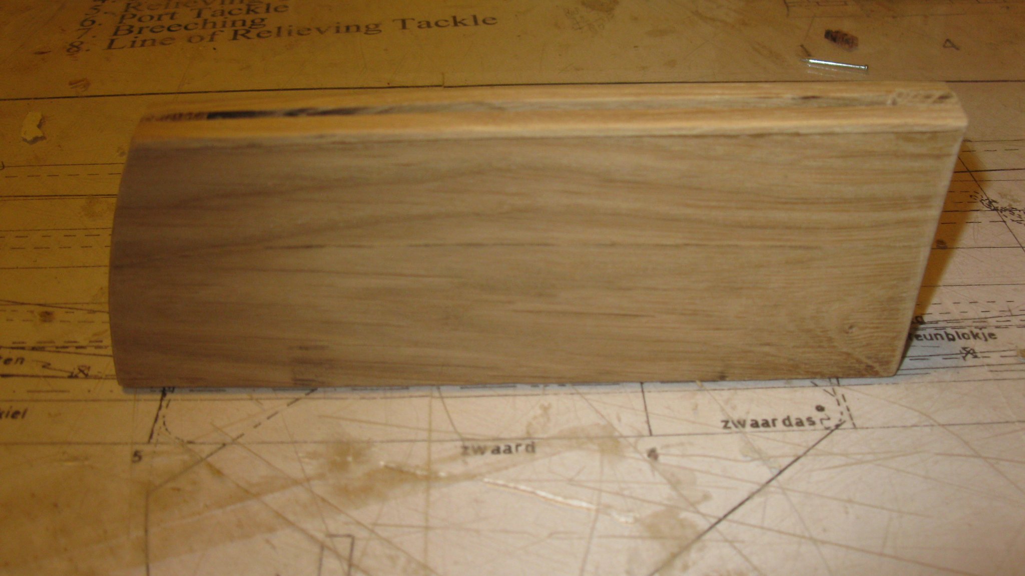
Gluing them together.
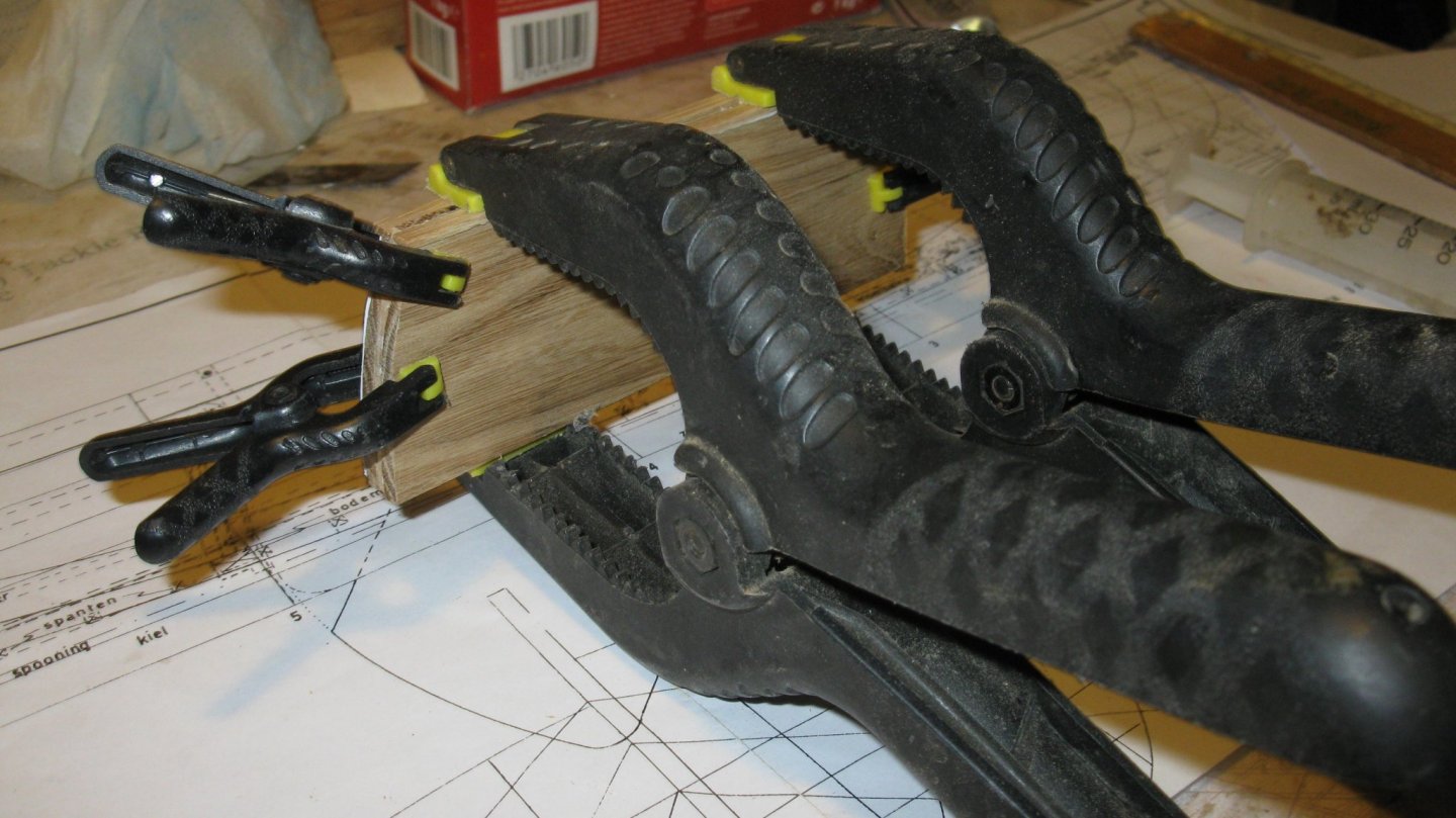
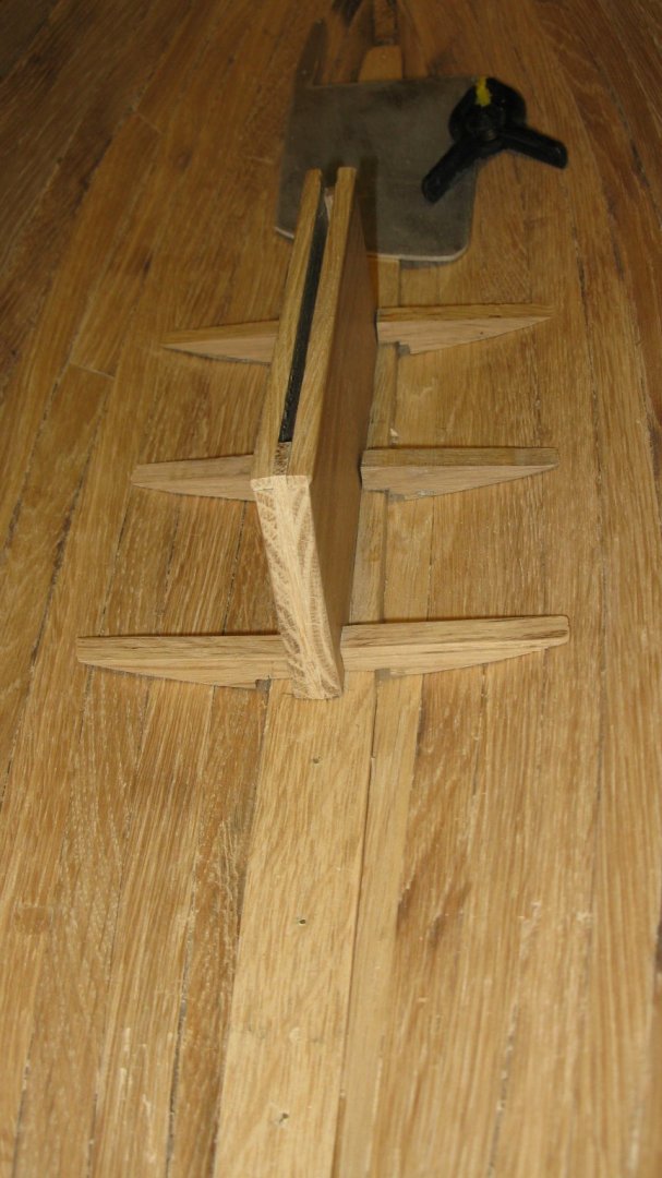
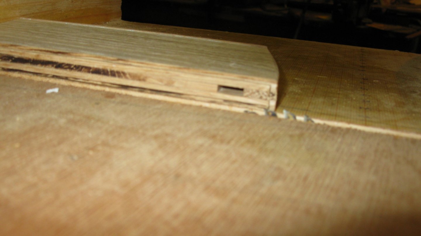
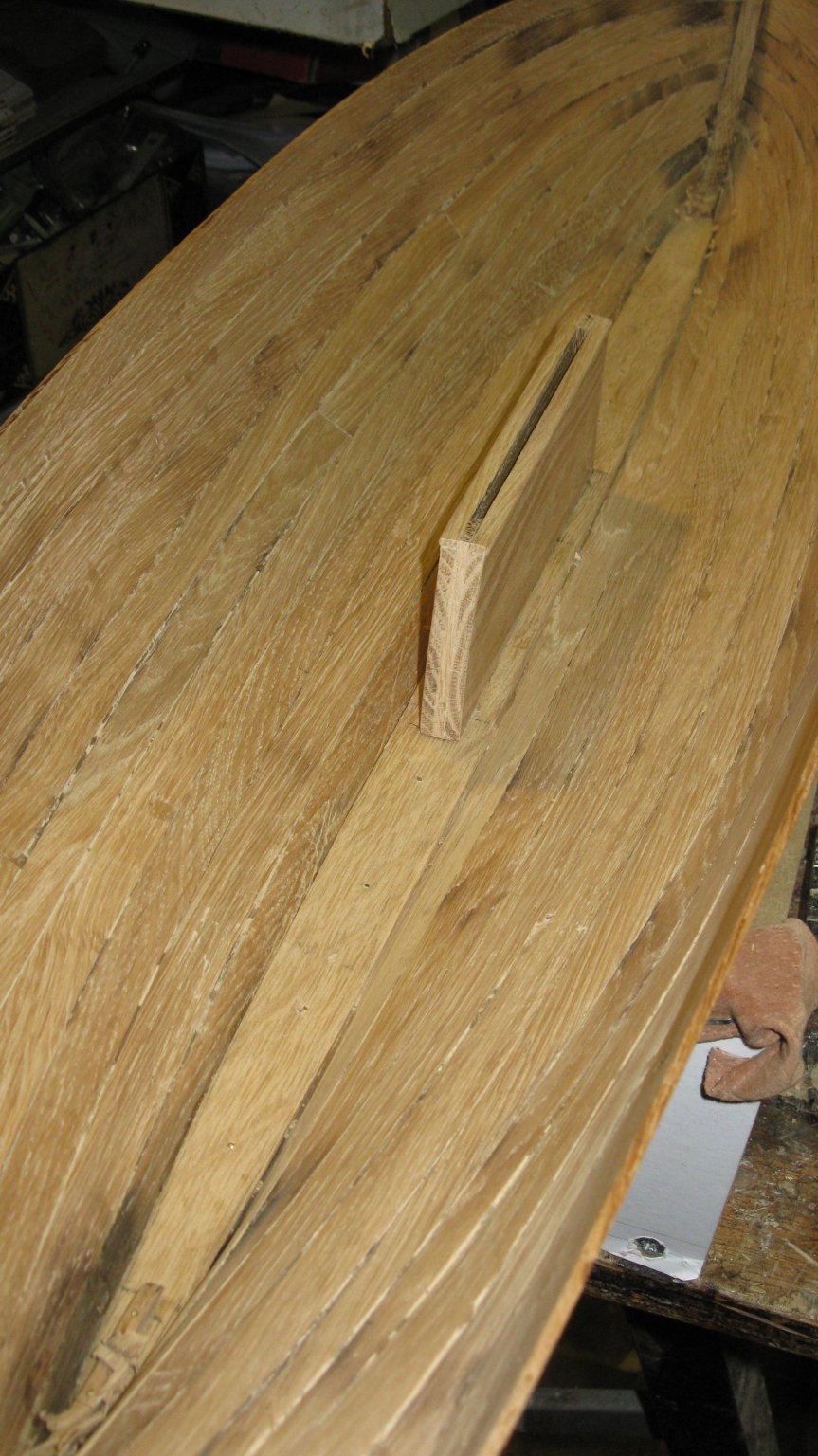
The center board case is standing on the keelson with a slot and groove connection. I make the slots in the case with the table saw.

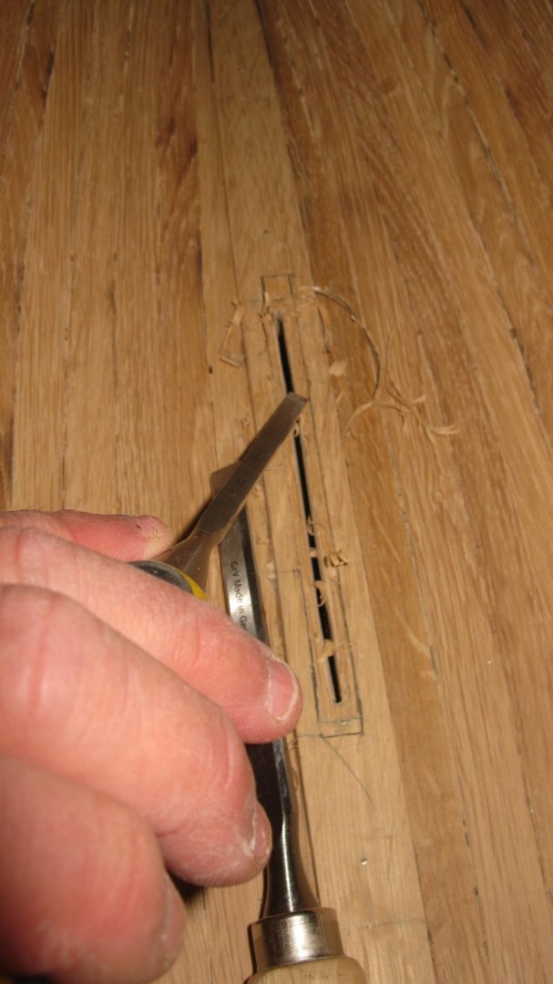
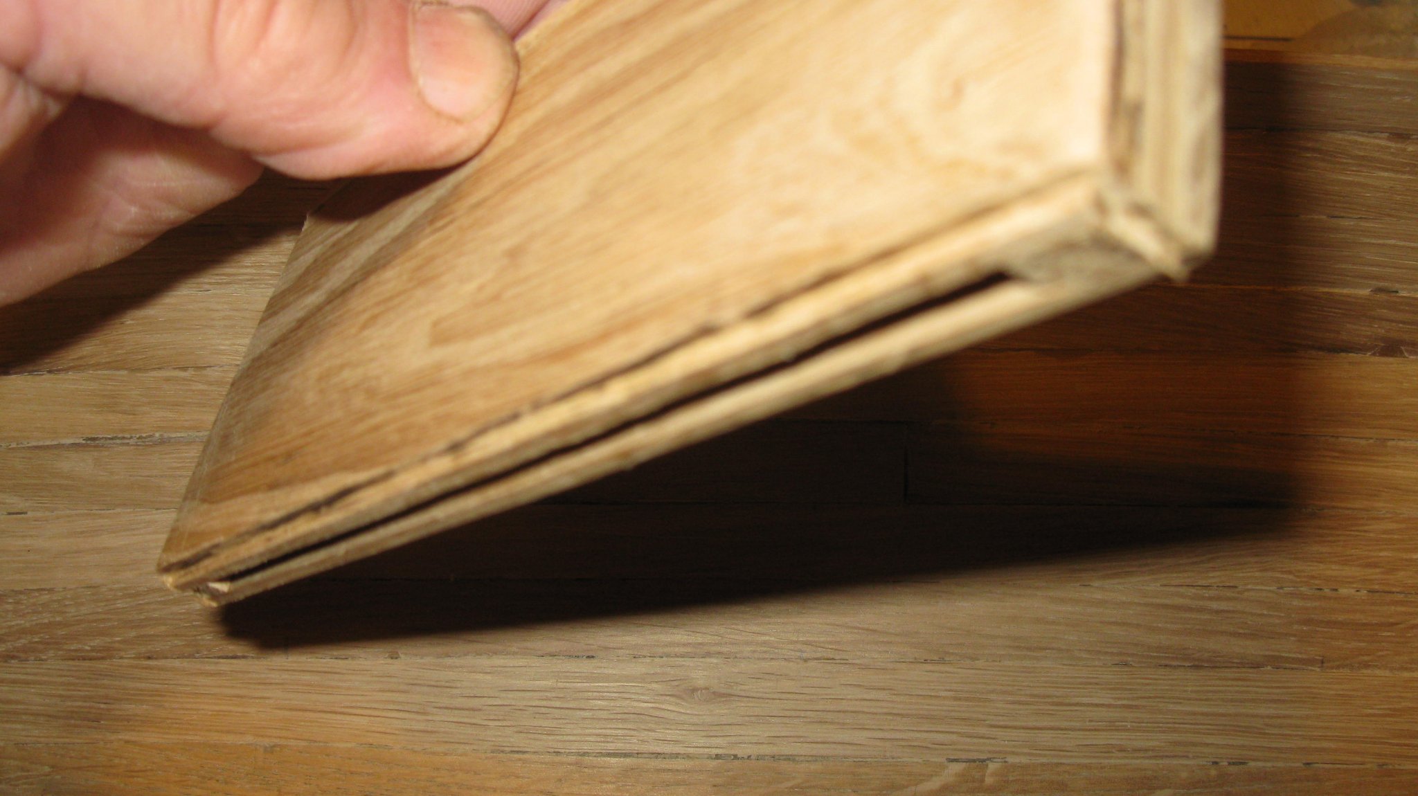
The groove in the keelson is stabbed with the chisel.
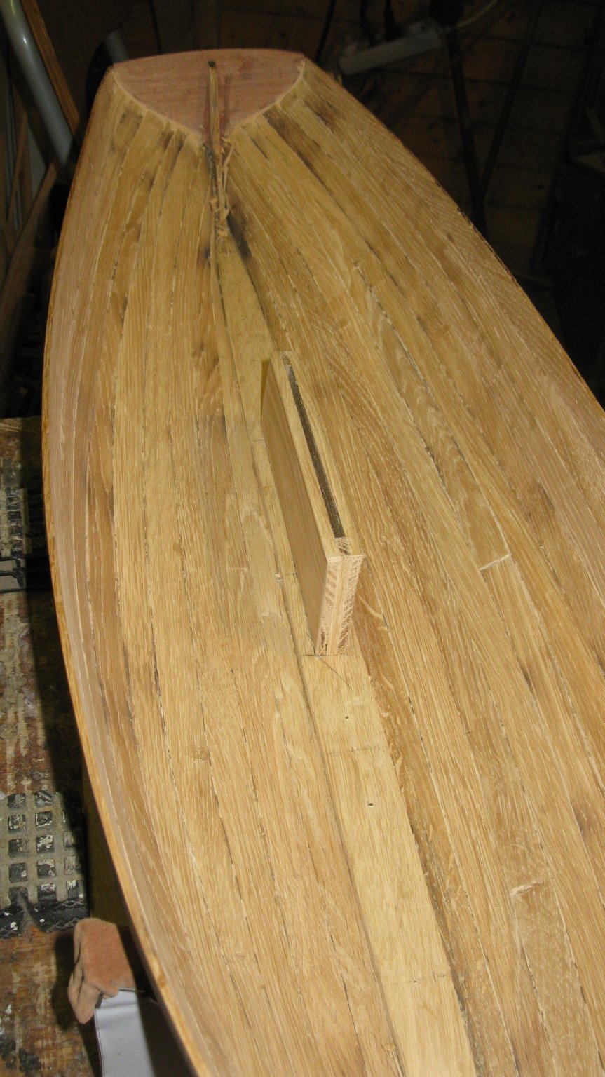
The center board box in its position.


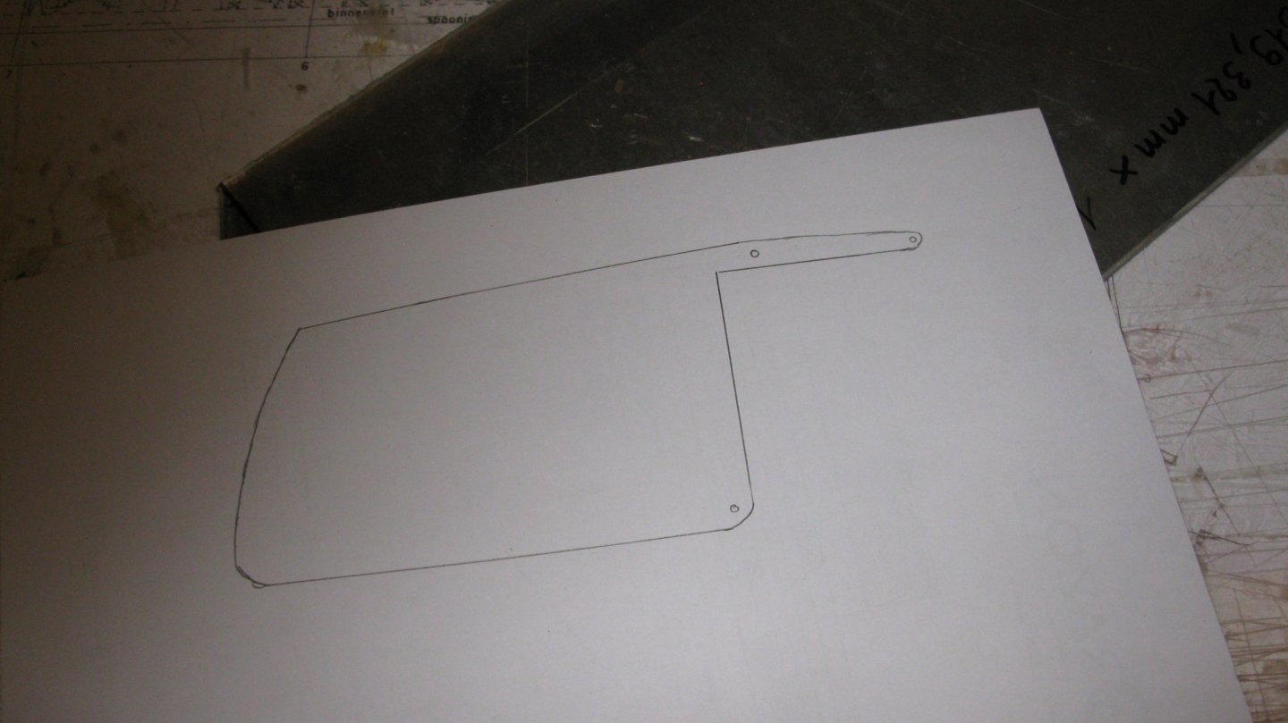
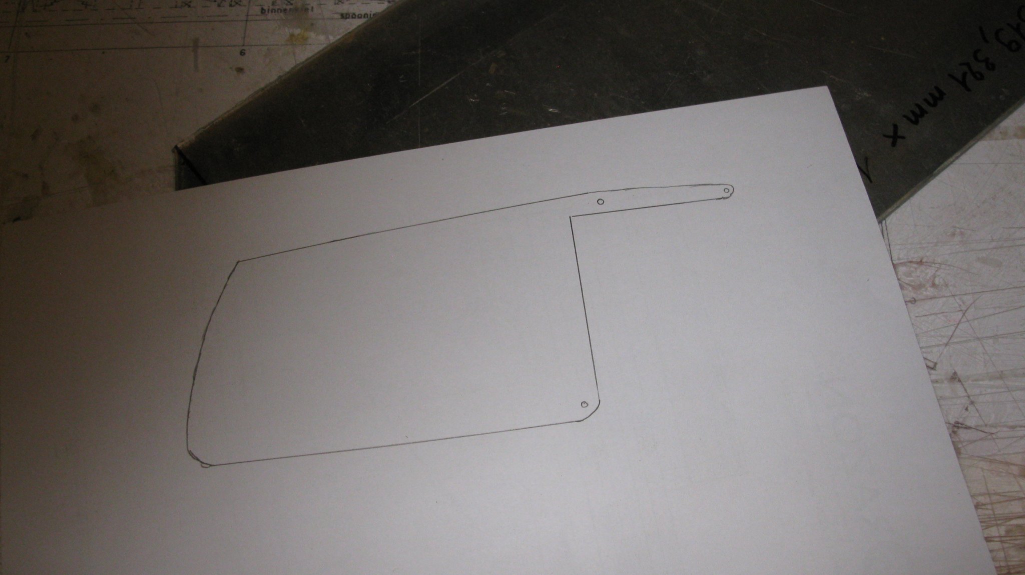
Paper template of the center board to glue on a 2mm thick aluminum plate.
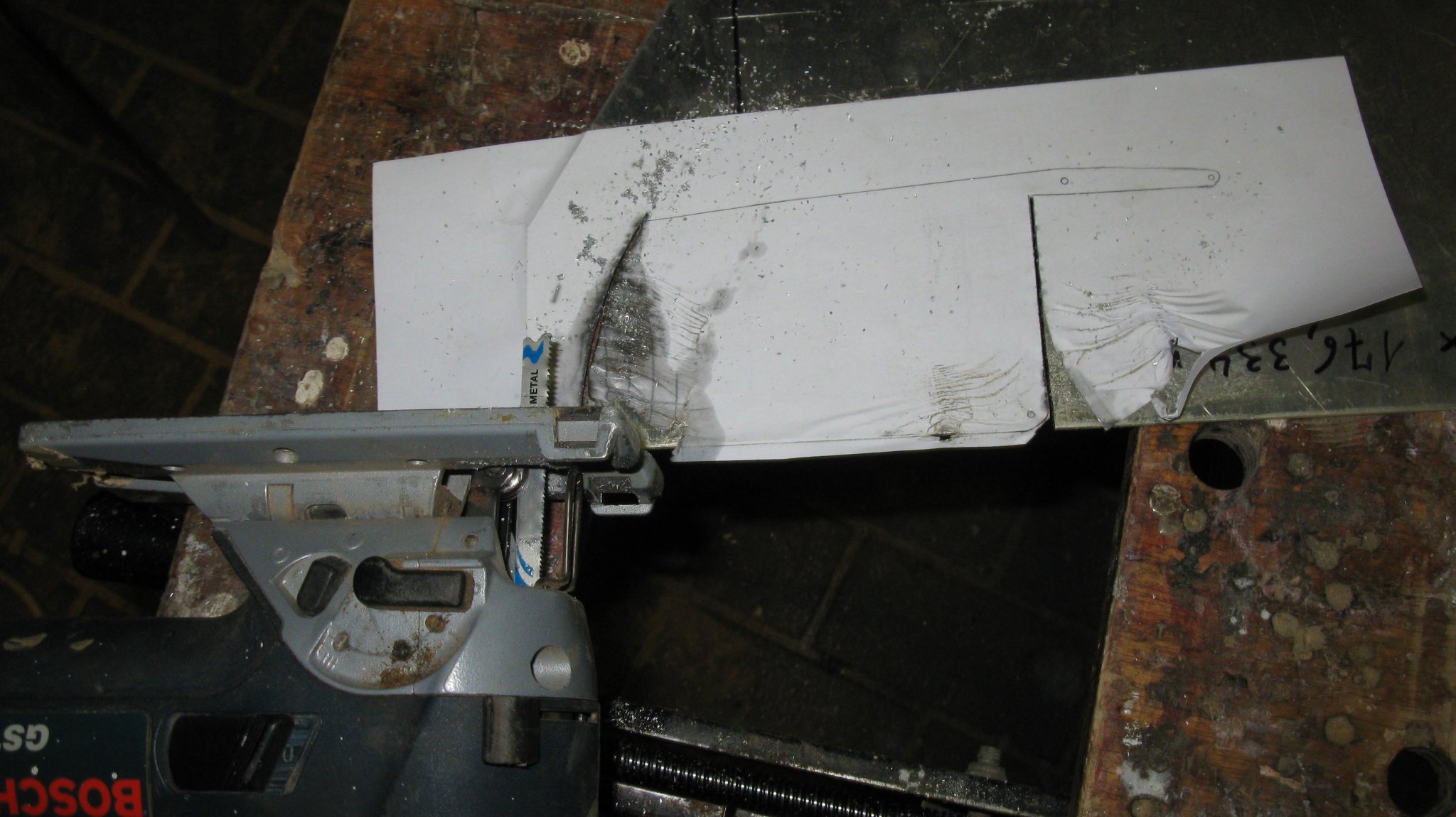
Sawing out the center board with the jigsaw. I lubricate the saw with some fuel oil.

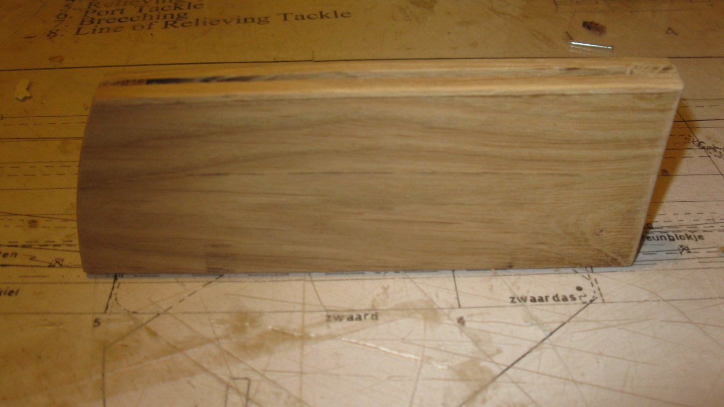
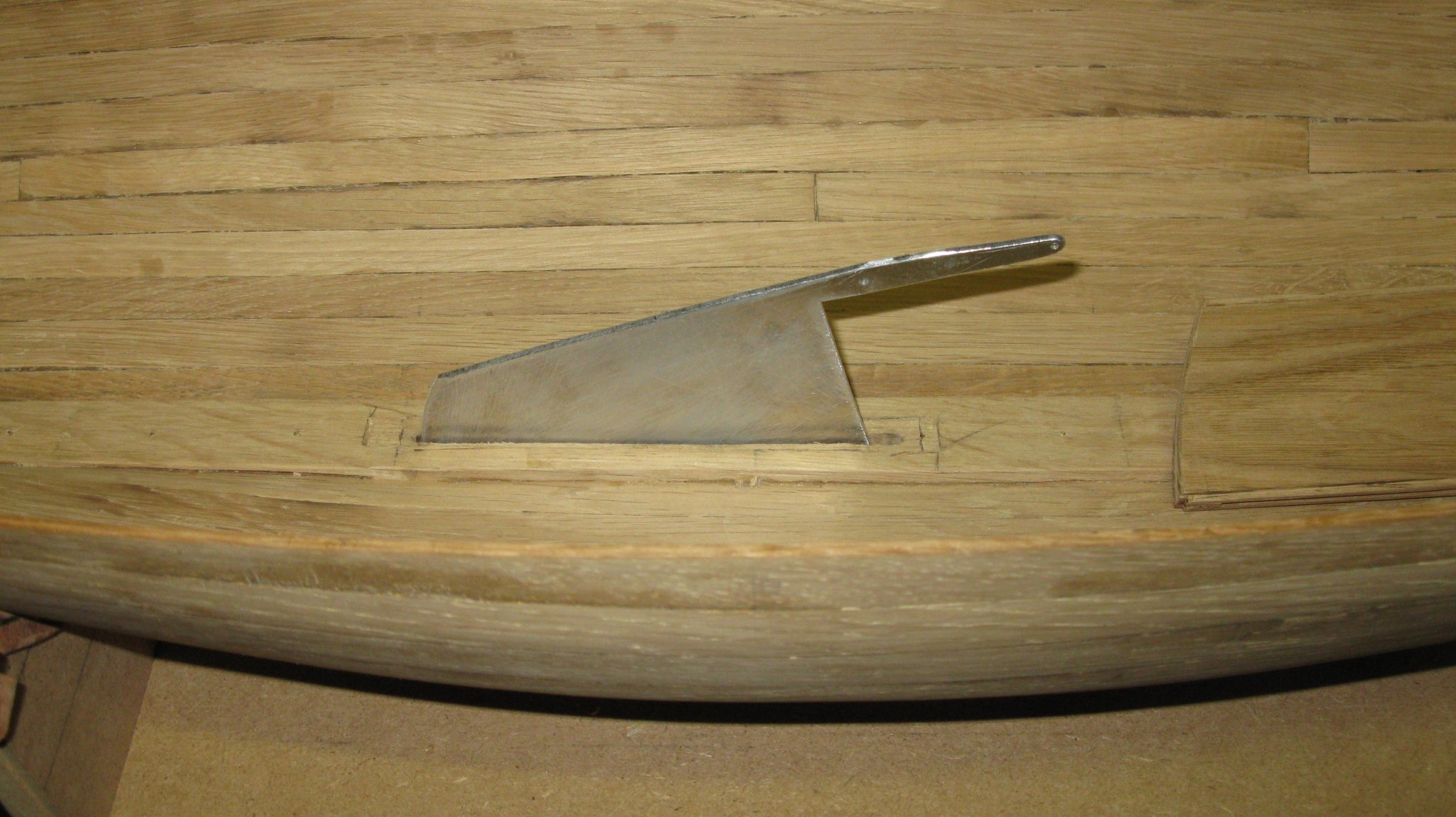
The center board sawed and filed.
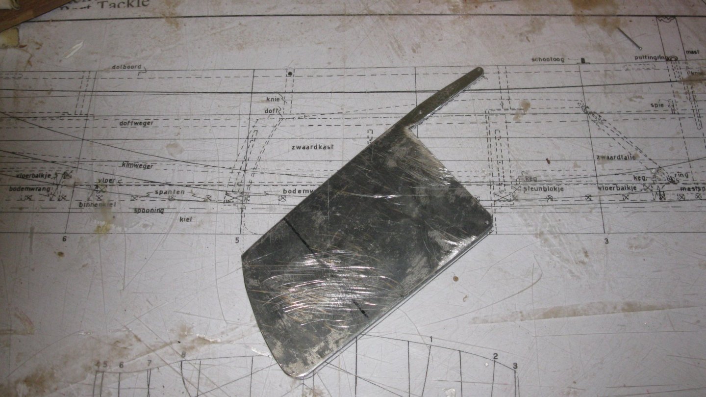
Fitting the board in the slot.


with the center board case...

-
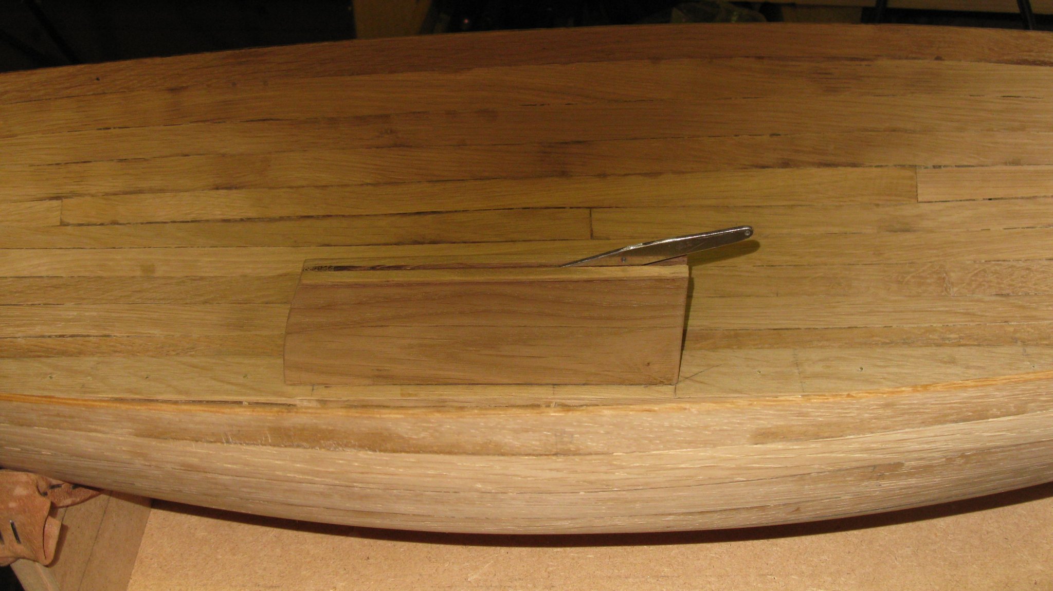
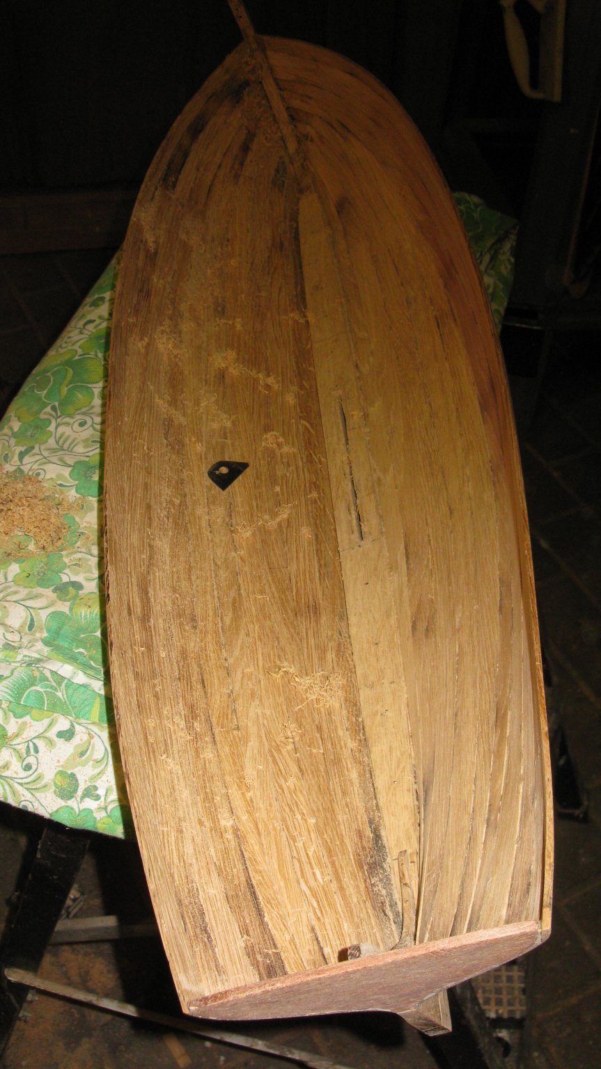
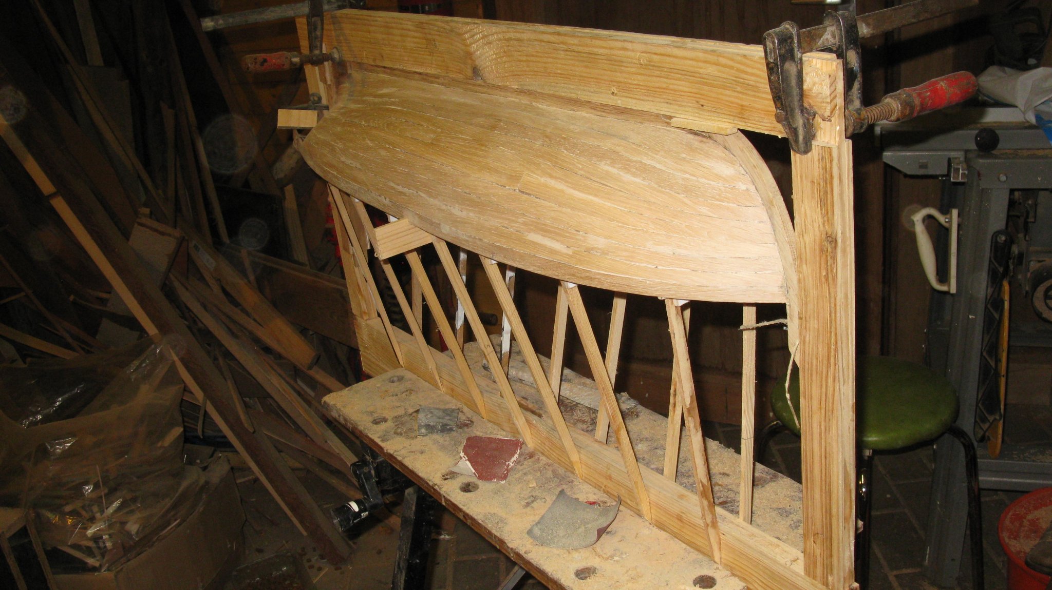
The hull, released from the board. The excesses of the planks at the transom are sawn off.

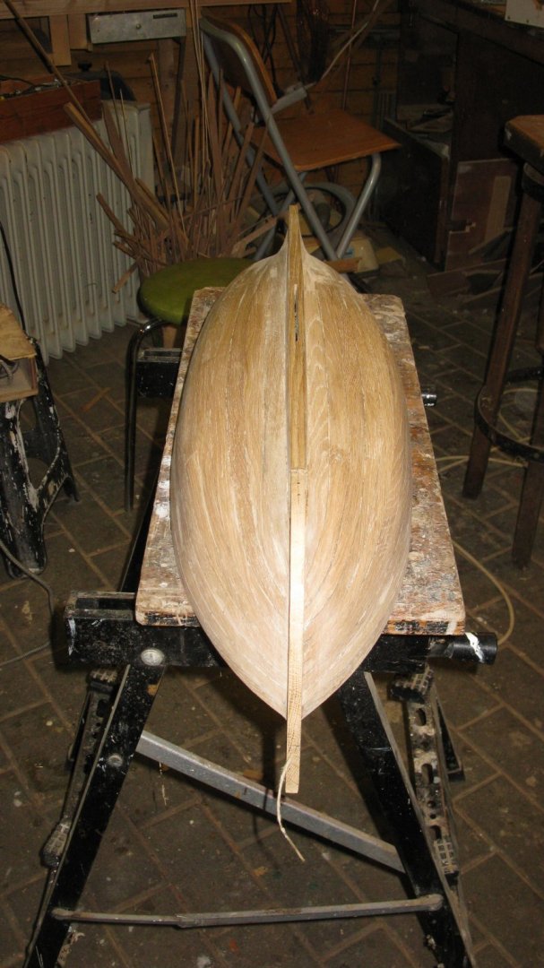
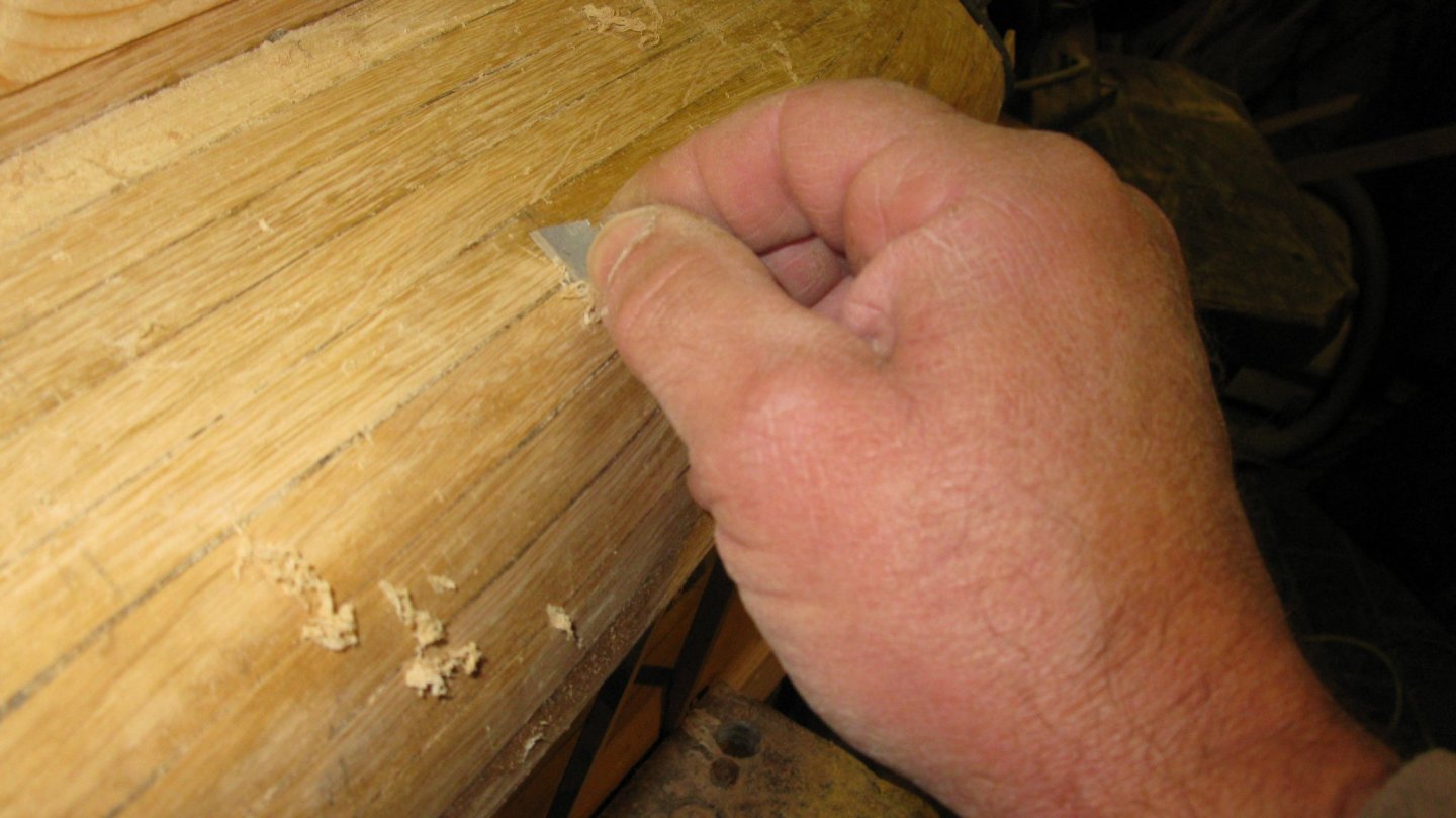
The surface of the inside of the hull is a bit rough and here and there you can see the traces of the paint stripper heat gun.
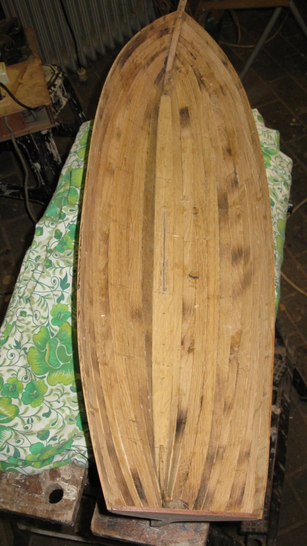
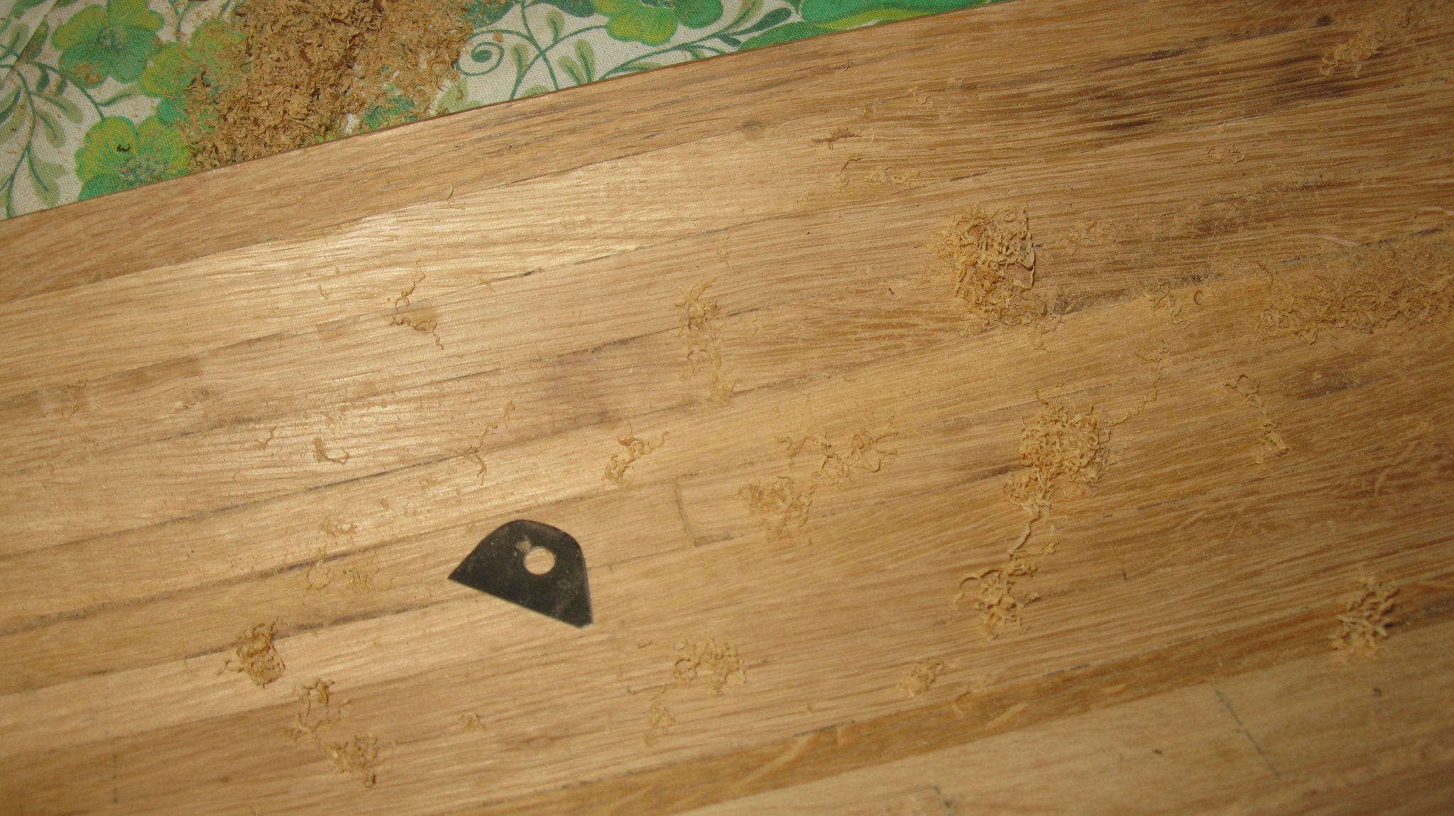
I crape the unevenness at the inside of the hull away. To reach all the inside curves of the hull, I file a small rounded scraper out of a piece of a cutter blade.


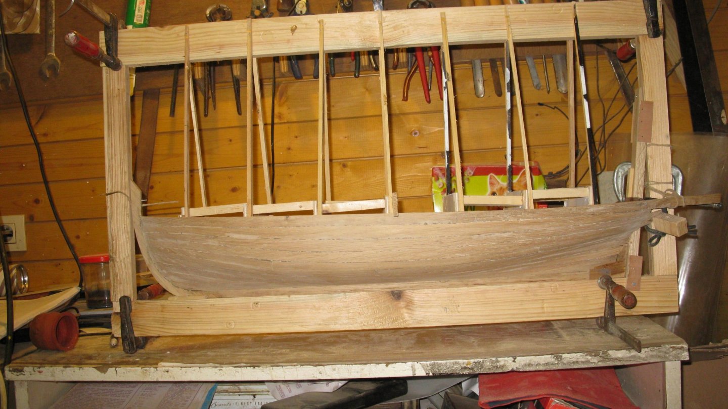
The inside is cleaned up.
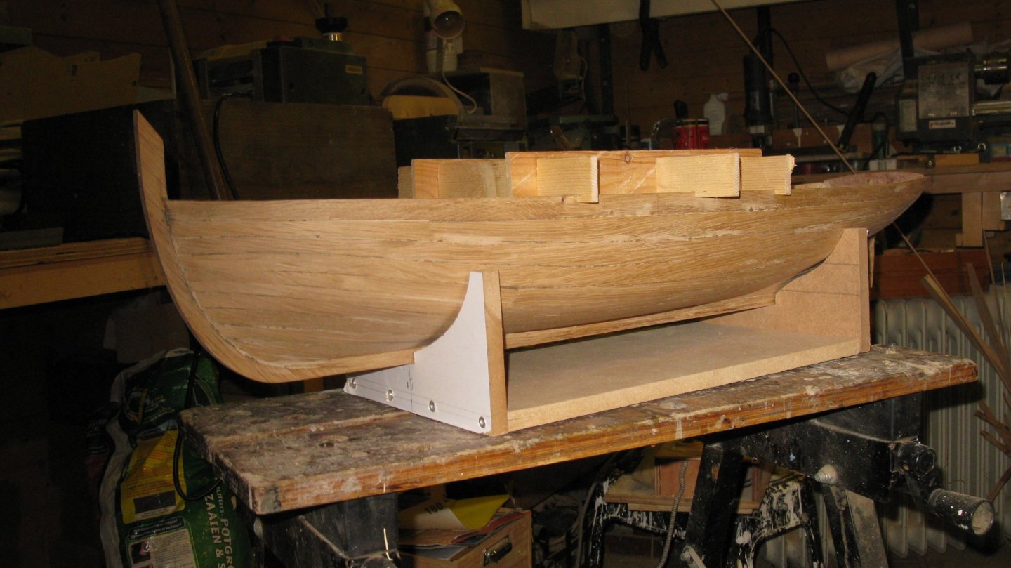
The hull waiting in its new chair for further treatment.

-
-
-
-
The last episode in the smack cross section story is the evaluation of the model during the model discussion of the modeling club last Friday. There the evaluators are much more demanding than my local modeling friends of post 196. The model discussion is moderated by a senior modeler with a lot of experience and a critical eye.
.thumb.jpg.8c75337a9db458a413ba0d83cf267646.jpg)
The author of the cross section handout was also present (right on the picture below). Before his retirement he was a ship carpenter. My model is thus a bit his spiritual child, he examines it with a lot of attention for detail.
In general all comments were positive.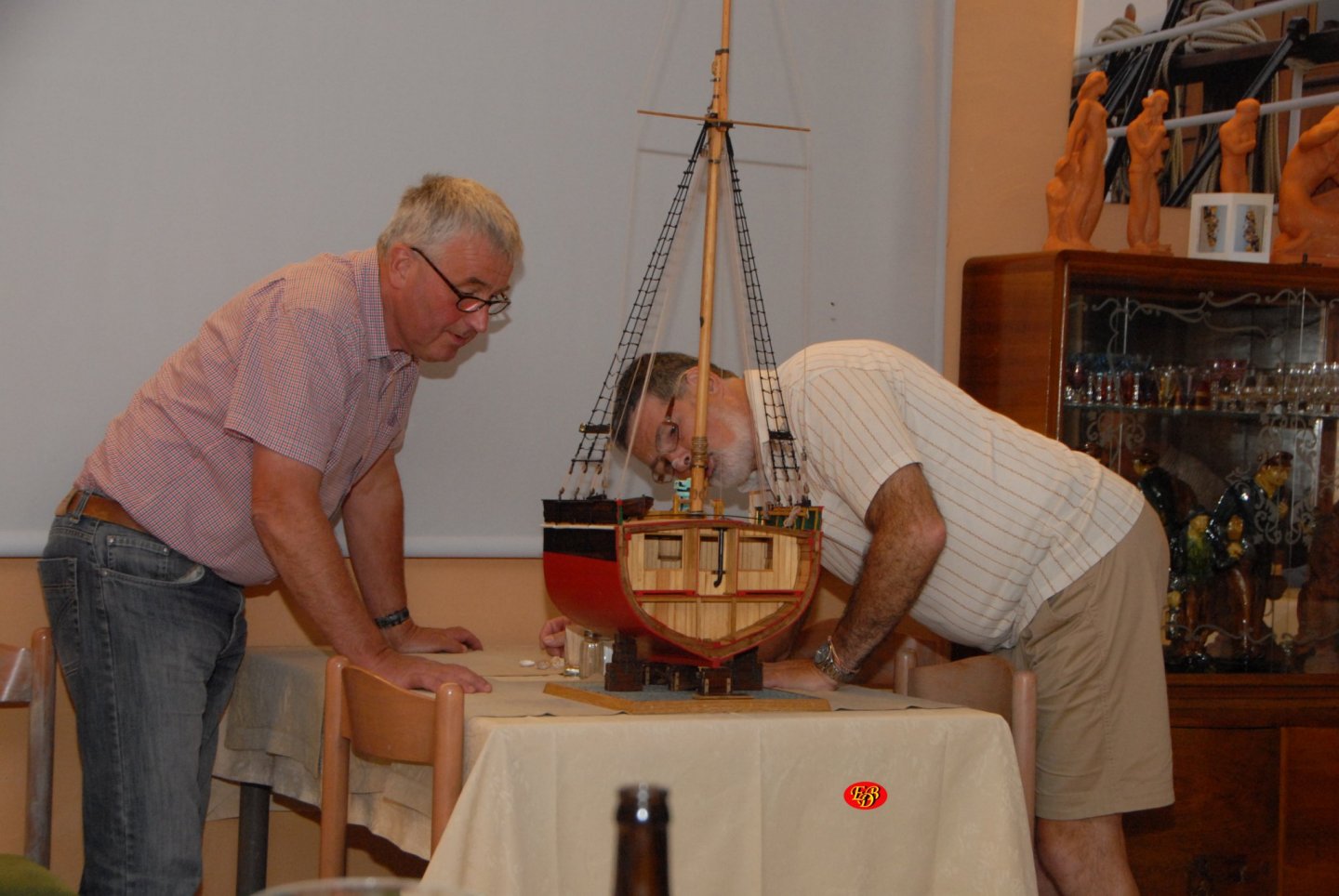
-
27 minutes ago, Mirabell61 said:
Hello Geert,
congrats, I know its an exiting moment, when the shell is removed from the mold, now you certainly will be starting with the framework.....
Nils
Thanks Nils, next thing will be the center board case and then the frames.
- Mirabell61 and mtaylor
-
2
-
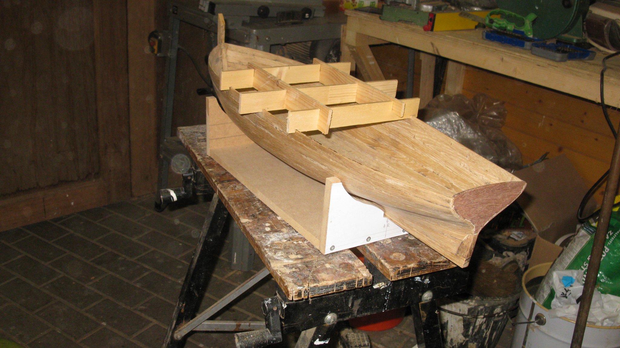
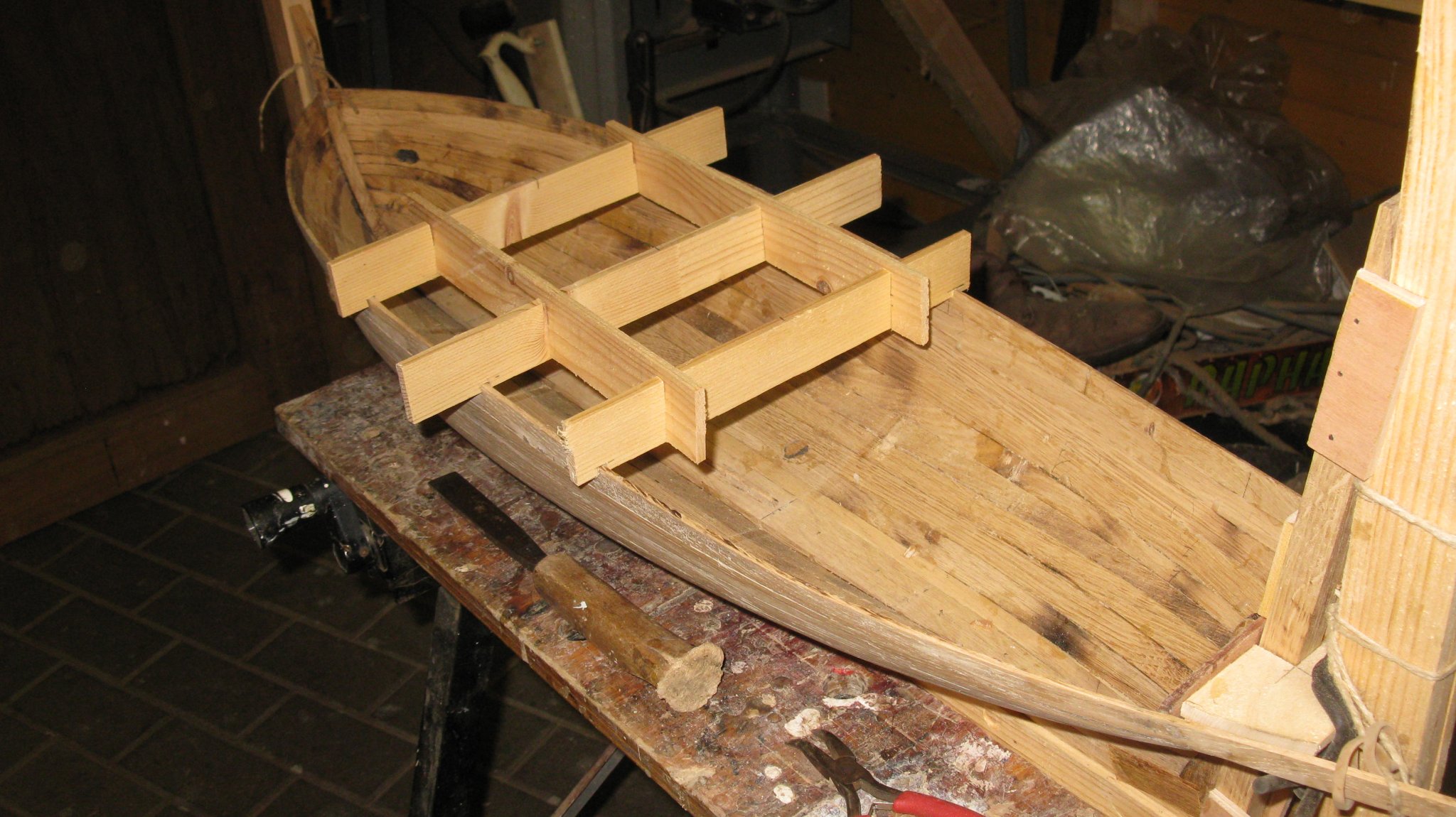
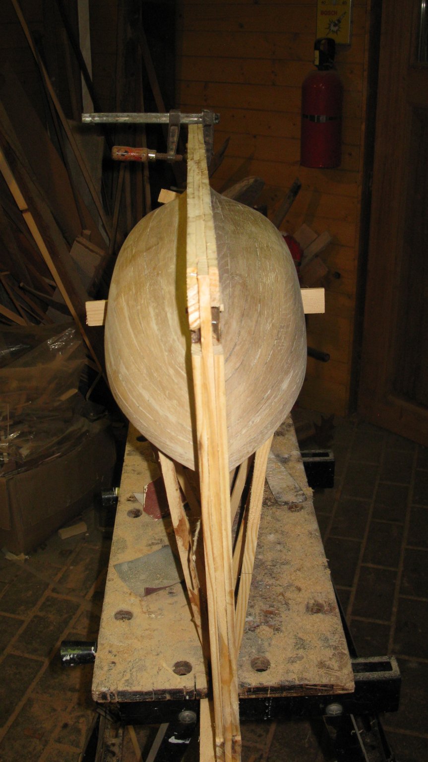
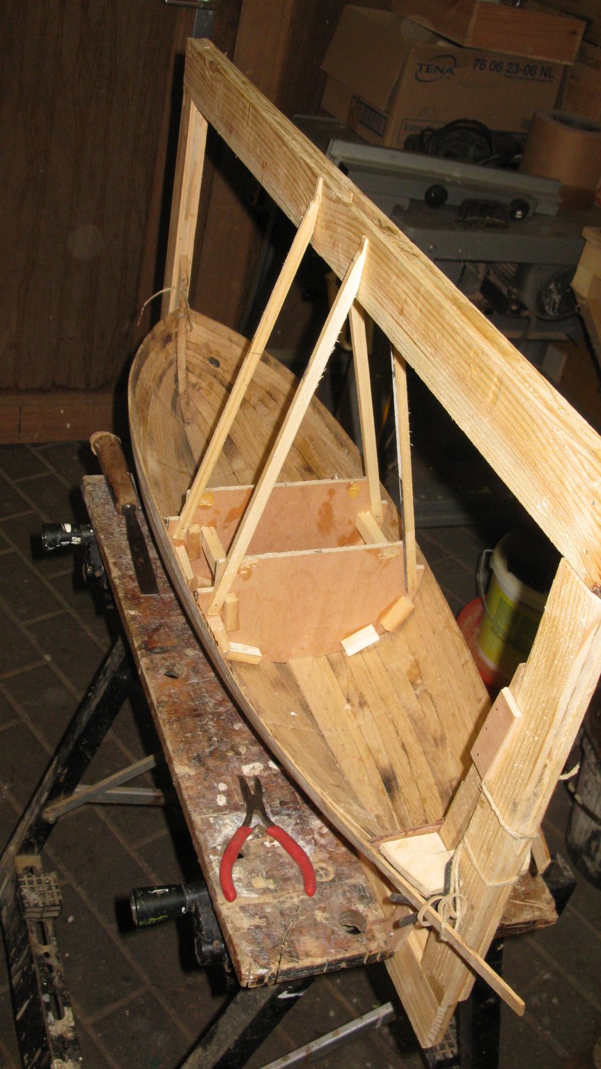
The shell is surprisingly solid. I make some supports to hold the hull on its width anyway.

Thank you to follow.
Thank you for the likes.
And thank you for the constructive comments.
Till next week!
- mtaylor, GrandpaPhil, FriedClams and 8 others
-
11
-
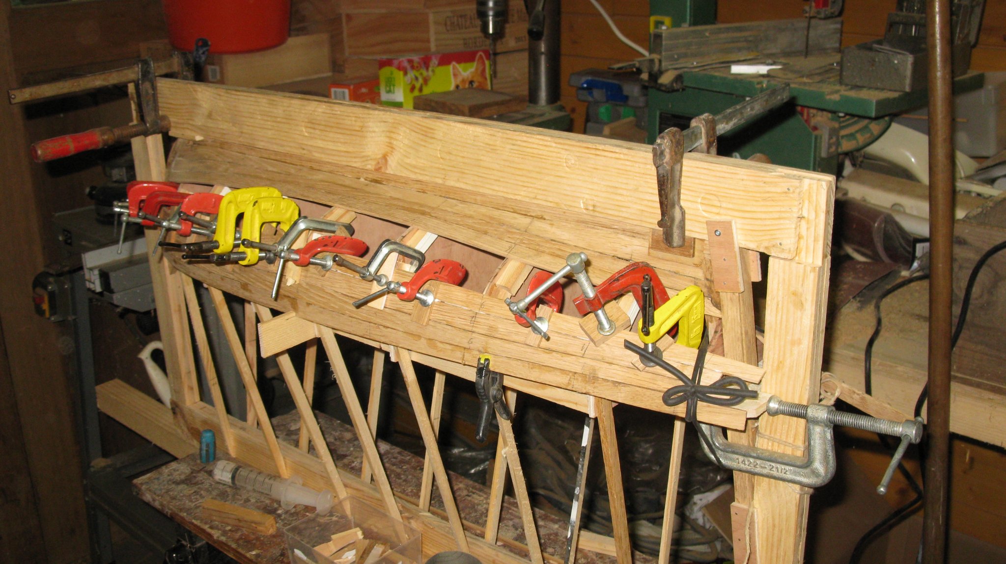
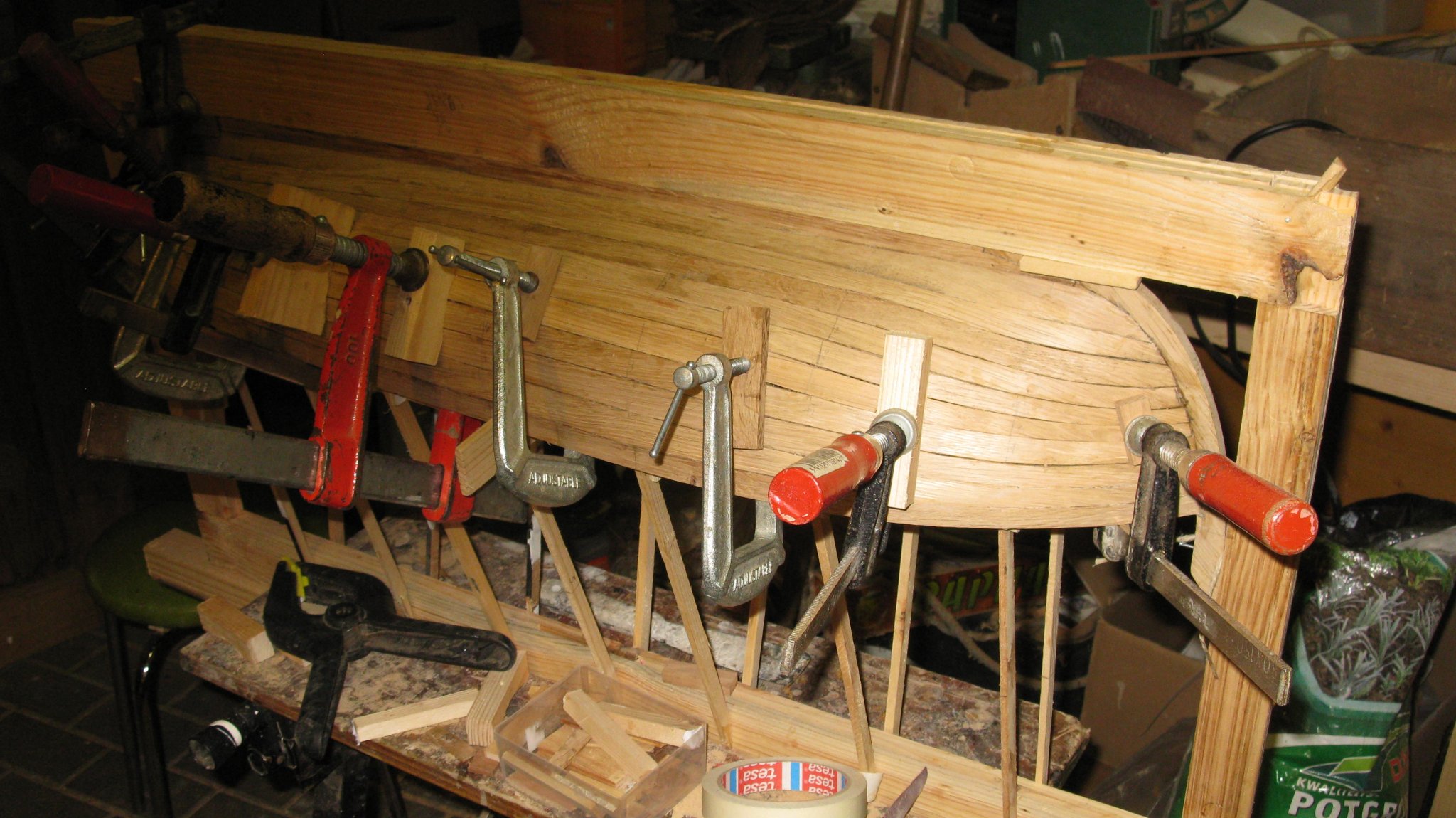
With an increasingly growing respect for real boat builders, I continue the laborious work of placing plank after plank.


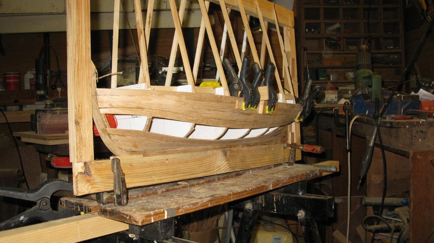
Fitting another template.

Only one more plank to go at both sides.
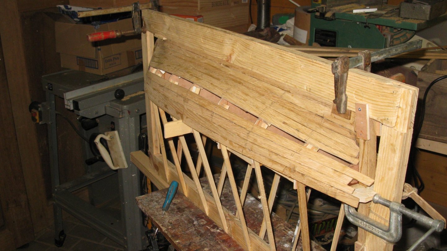
Port side completely closed.


Now filling up the starboard side

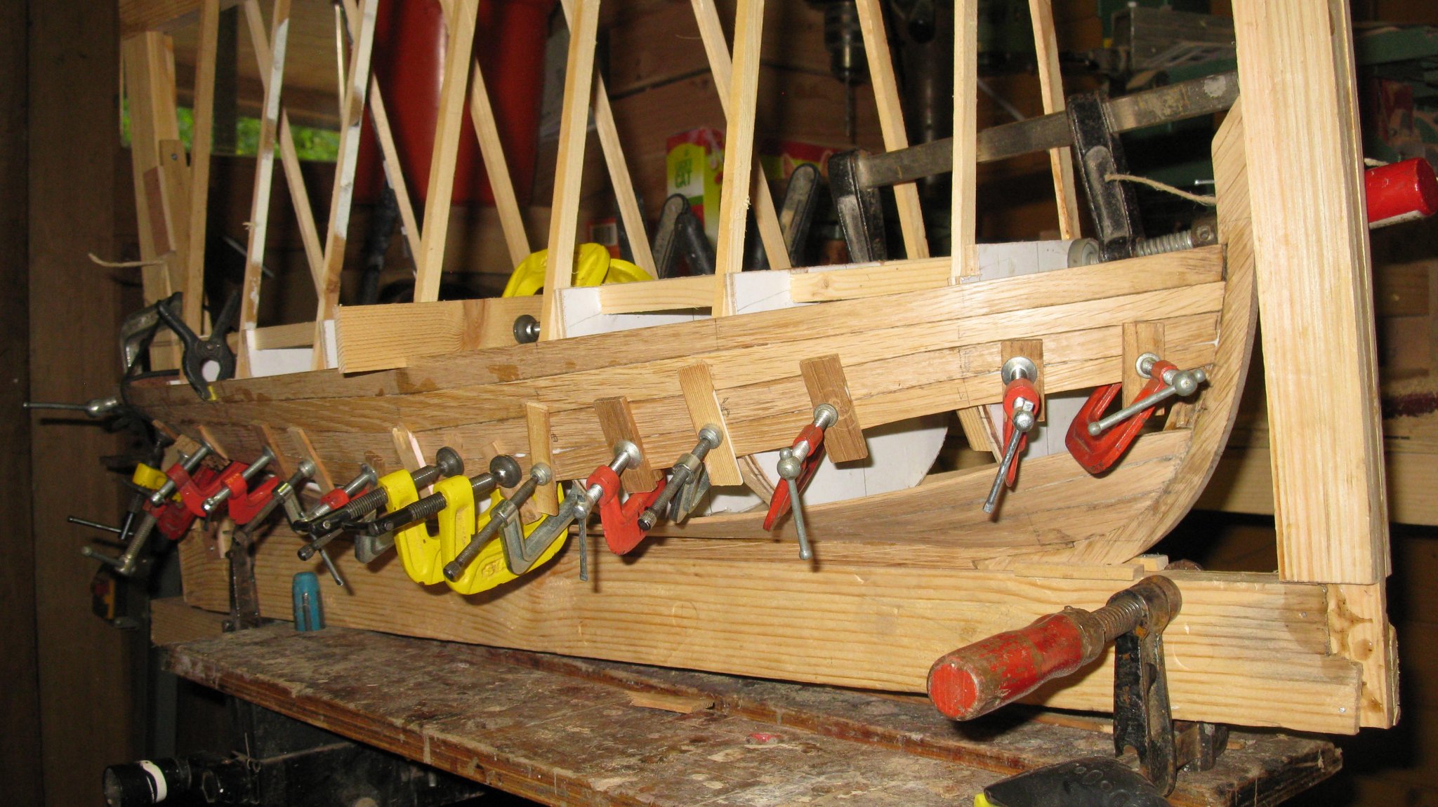
When the glue dried up, There is glue residue and a lot of unevenness's on the hull therefore I scrape the surface.
The I sand the outside with sandpaper grit 080 up to 600.


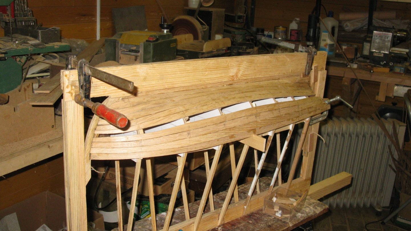
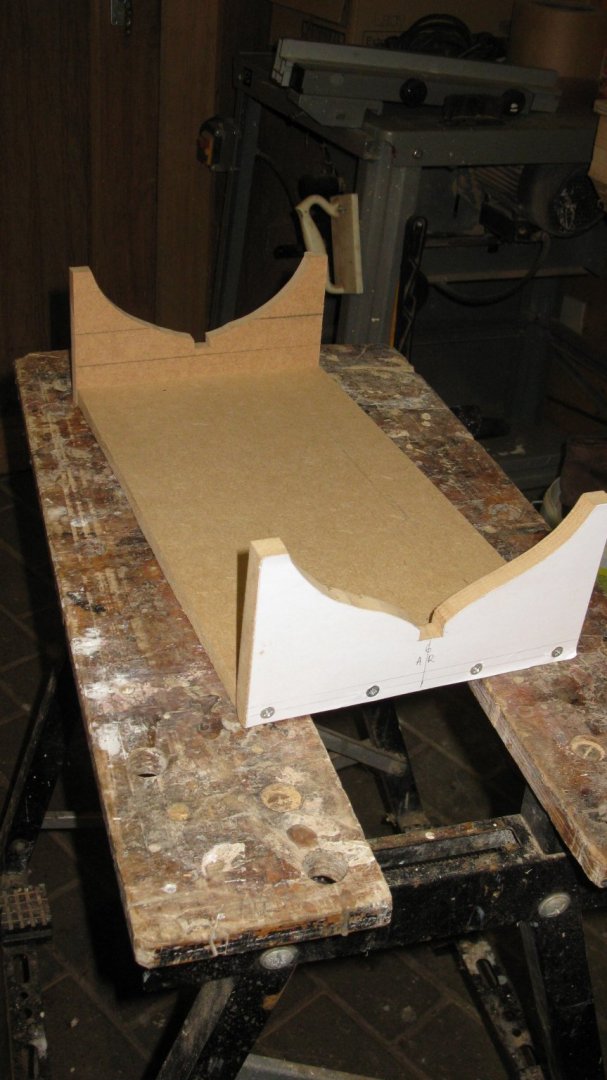
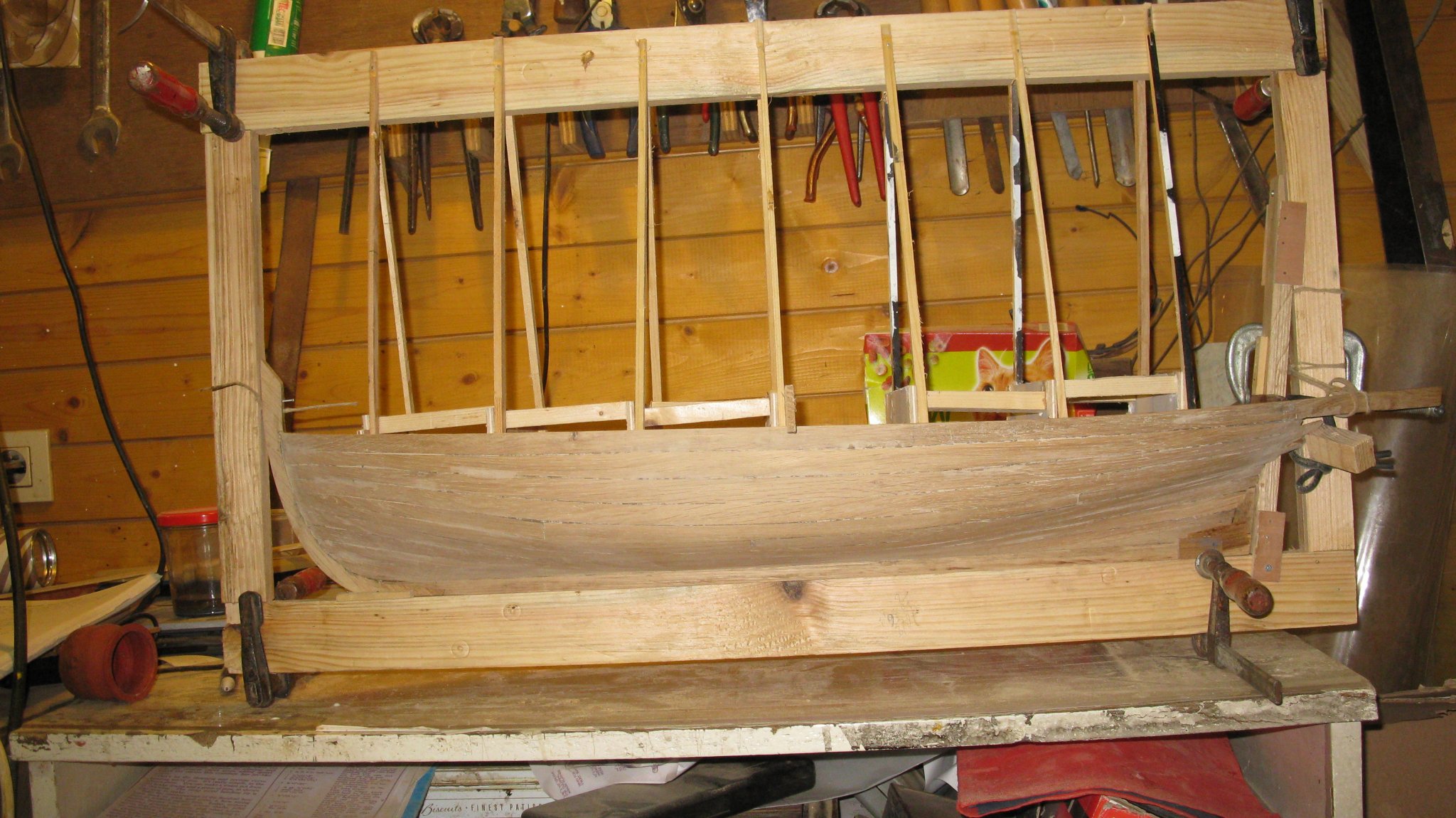
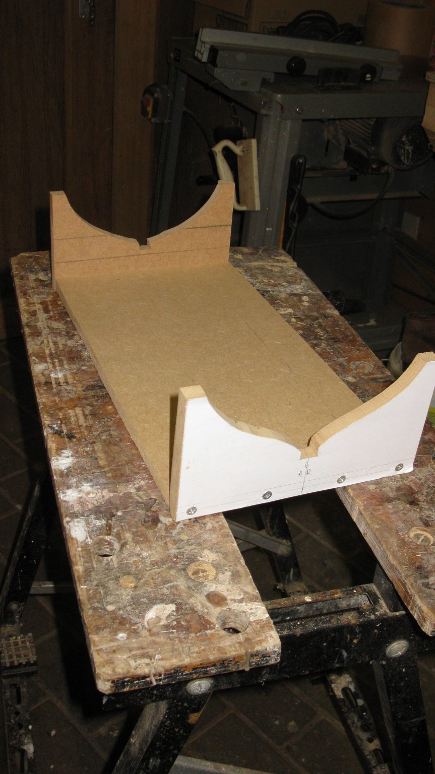
Before taking the hull from the building board, I make a new chair in which I can finish the model.
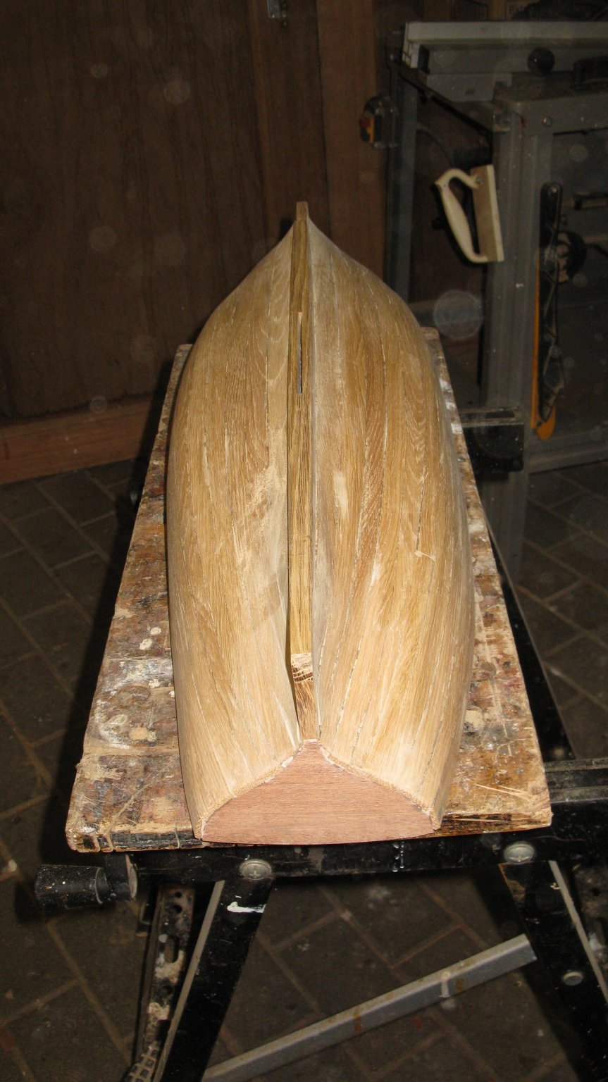
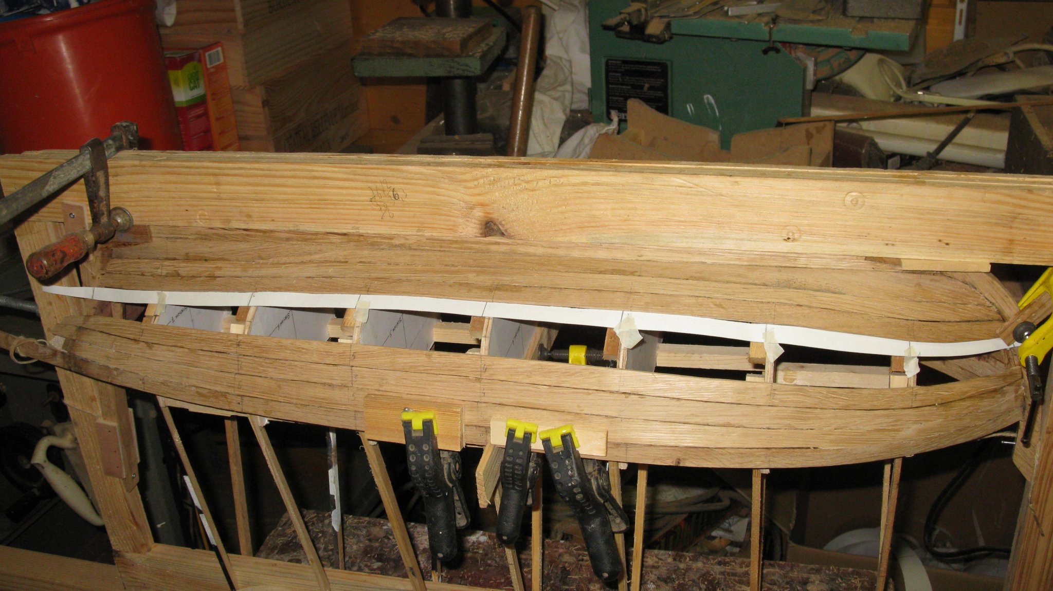
Now it's time to lift it from the mold. I remove one after one the station boards. It is an exciting moment; will it keep its shape or will the shell collapse like a pudding?

- mtbediz, cog, GrandpaPhil and 5 others
-
8
-
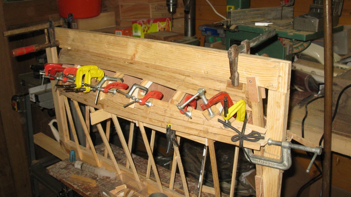
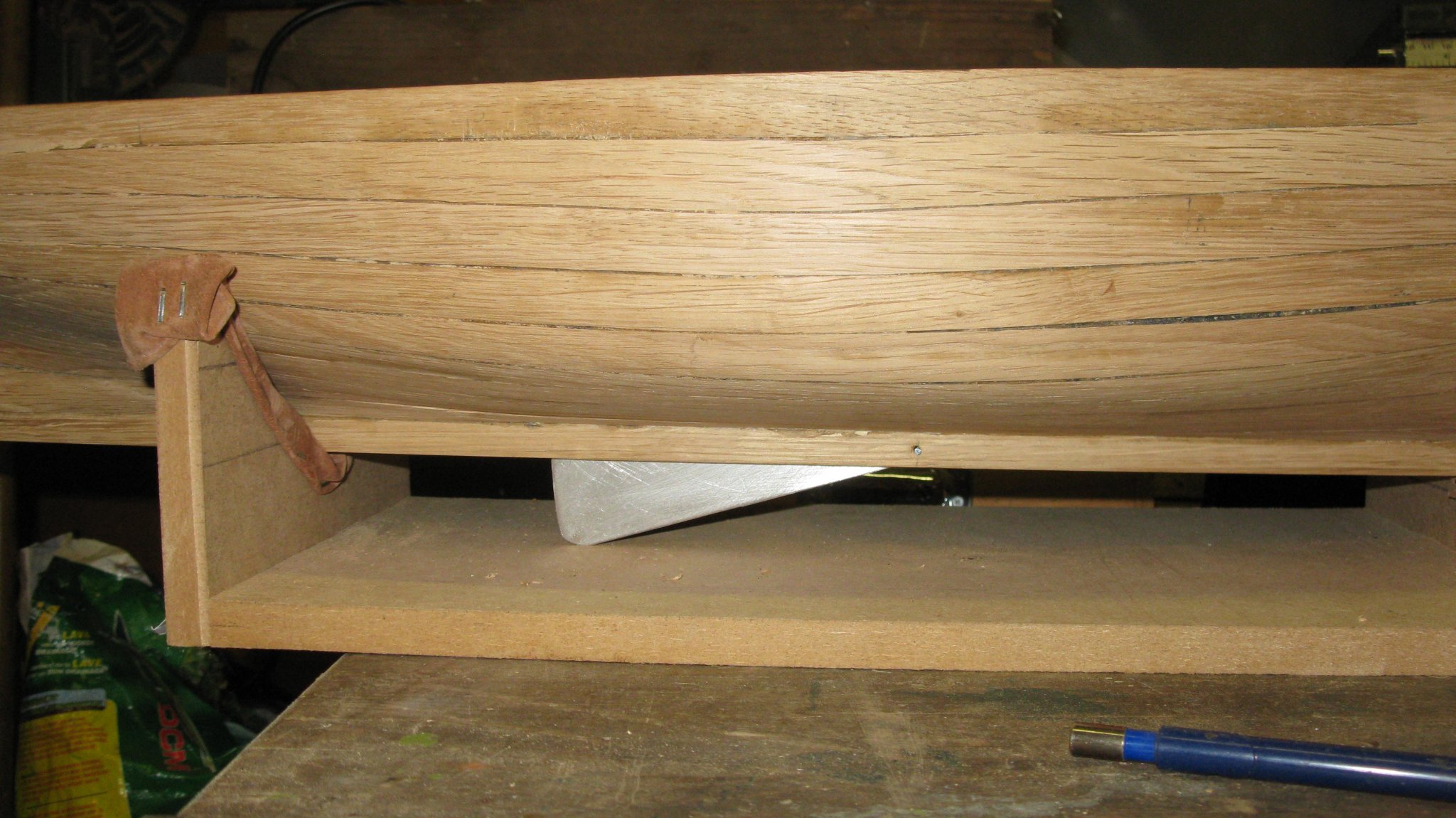
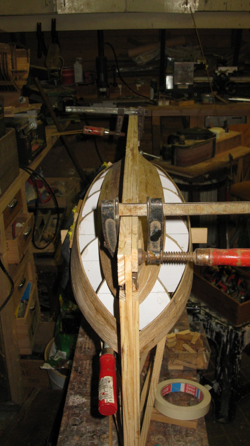
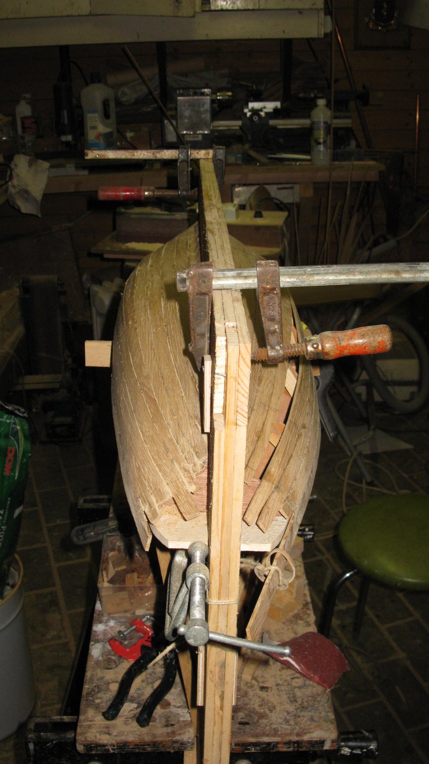
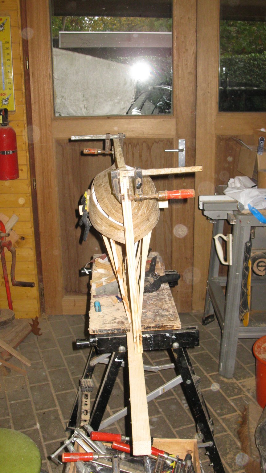
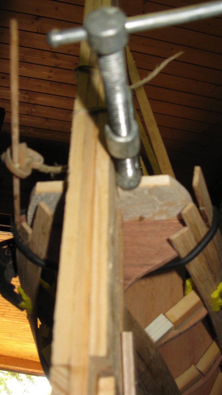
Another problem: By the force of clamping the planks, the stern is coming to sit askew. I have to unfasten all the planks from the stern. To make sure that the stern is remaining perpendicular to the keel is make a support to secure it.
Once the support is fixed, the planks can be re-glued to the stern.

-


.jpg.f7f2db6f54684e85e7b6a2aea8eb4815.jpg)


Miss Caroline by Bedford - Scale 1:8 - model of my full size build
in - Build logs for subjects built 1901 - Present Day
Posted
She is a beauty!