


G.L.
-
Posts
1,553 -
Joined
-
Last visited
Content Type
Profiles
Forums
Gallery
Events
Posts posted by G.L.
-
-
On 9/7/2019 at 9:17 AM, Jim Lad said:
What a delightful model. I'm glad I found your build log.
John
On 9/7/2019 at 12:05 PM, Bedford said:Just found this, very interesting
Thank you John and Steve,
I am glad that you're interested.
-
16 hours ago, Mirabell61 said:
Very nice block making Geert !
Nils
Thank you Nils, Are that the kind of blocks you will be needing for your zeesboot?
- mtaylor, Mirabell61 and mtbediz
-
 3
3
-
18 hours ago, mtbediz said:
Beautiful job sir. Will you complete her?
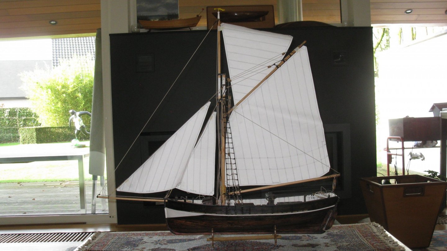
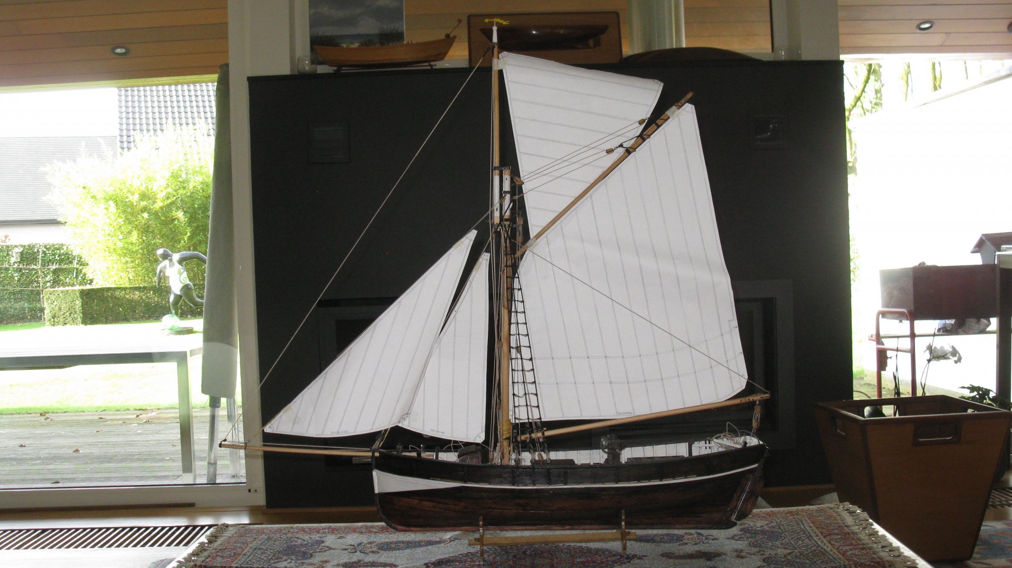
Yes Mustafa, that is as least the plan. Next thing to do is making the sails. The reason that it takes me so long is that I first will have to learn to work with the sewing machine. It is my plan to make sails first for my gaff sail boat because they are a lot less complicated. Below you see the model with the paper templates of the sails.
- KeithAug, mtaylor, GrandpaPhil and 1 other
-
4
-
-
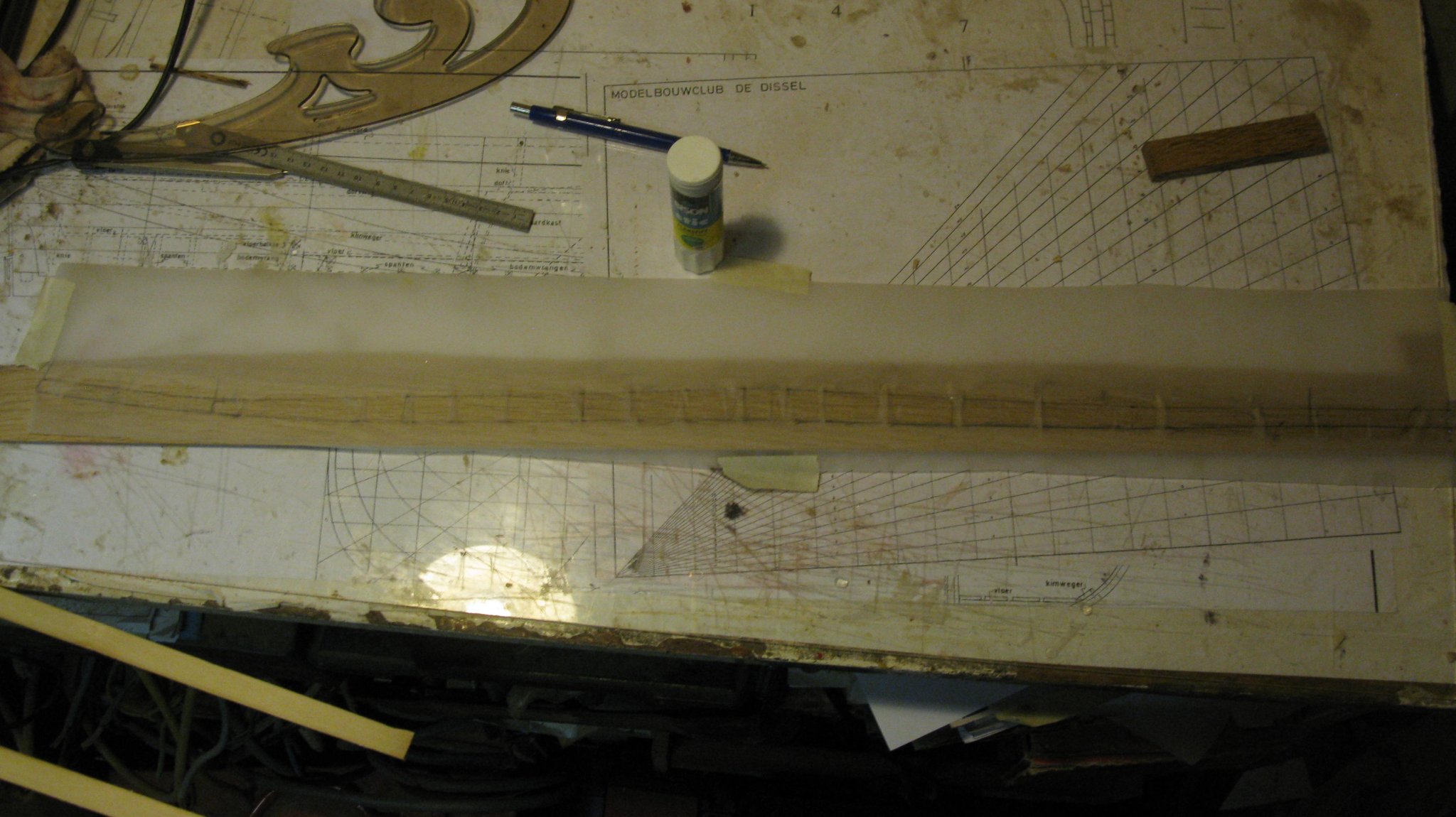
I experience that this method of lofting the strakes is not ideal. It worked well for my shrimper because the planks were maximum half a ship's length long. On this model they stretch from bow to stern, therefore their shape must be more accurate or they wrench or there are gaps between the strakes. I have to try another system.
I try it this way: I attach a narrow strip of fairly stiff drawing paper along the edge of the strake that I want to draw. I take care not to wring the strip along the edge of the adjoining plank.
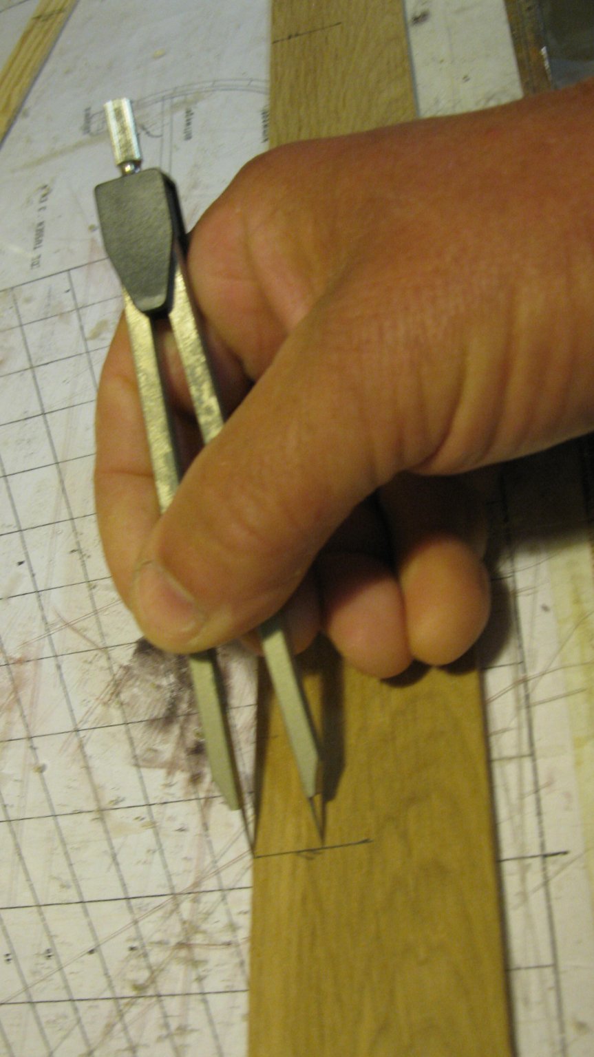
Then I draw from the inside of the hull with a sharp pencil along the plank edge the edge shape on the paper. I mark also the stations on the obtained pencil line.

The paper can be taken off the model; the line must now be retouched until it is smooth enough to follow the last strake.
Now it is again the usual procedure of measuring the stroke width and to displace the widths to the paper pattern.

The obtained shape of the plank.
The pattern cut out and on the model to check the connection to the adjacent plank.
The pattern glued on the plank to saw it out.
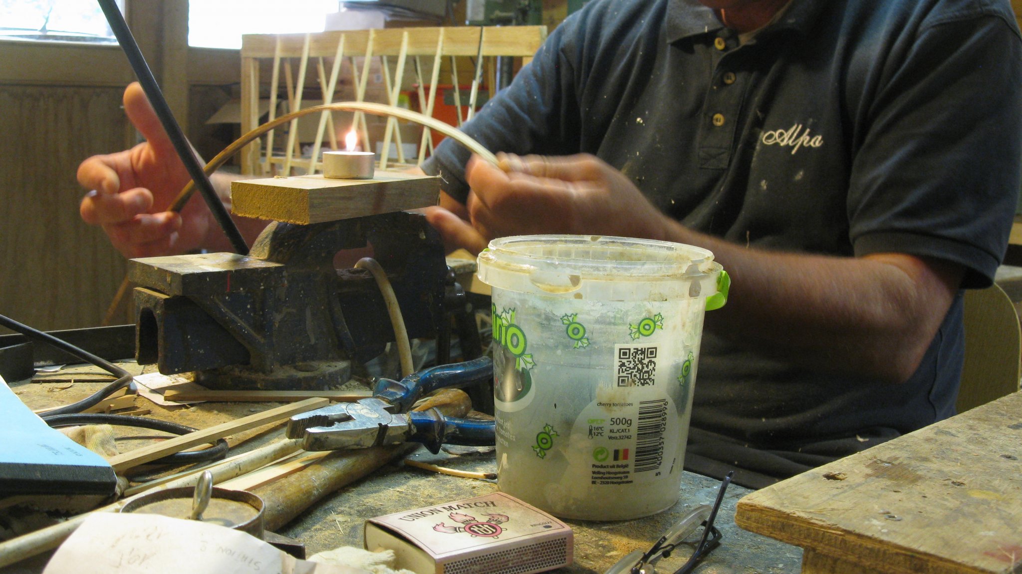
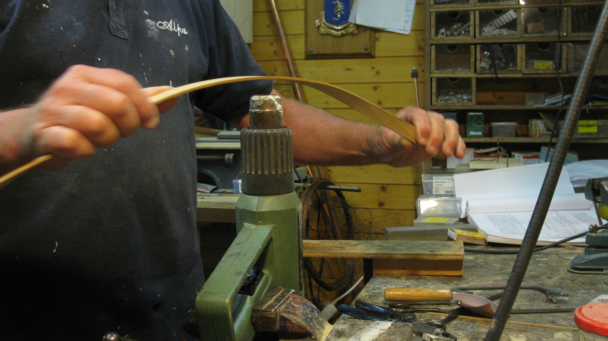
After the plank was curved above the heat of the paint stripper heat gun.
Holding the plank on its position.
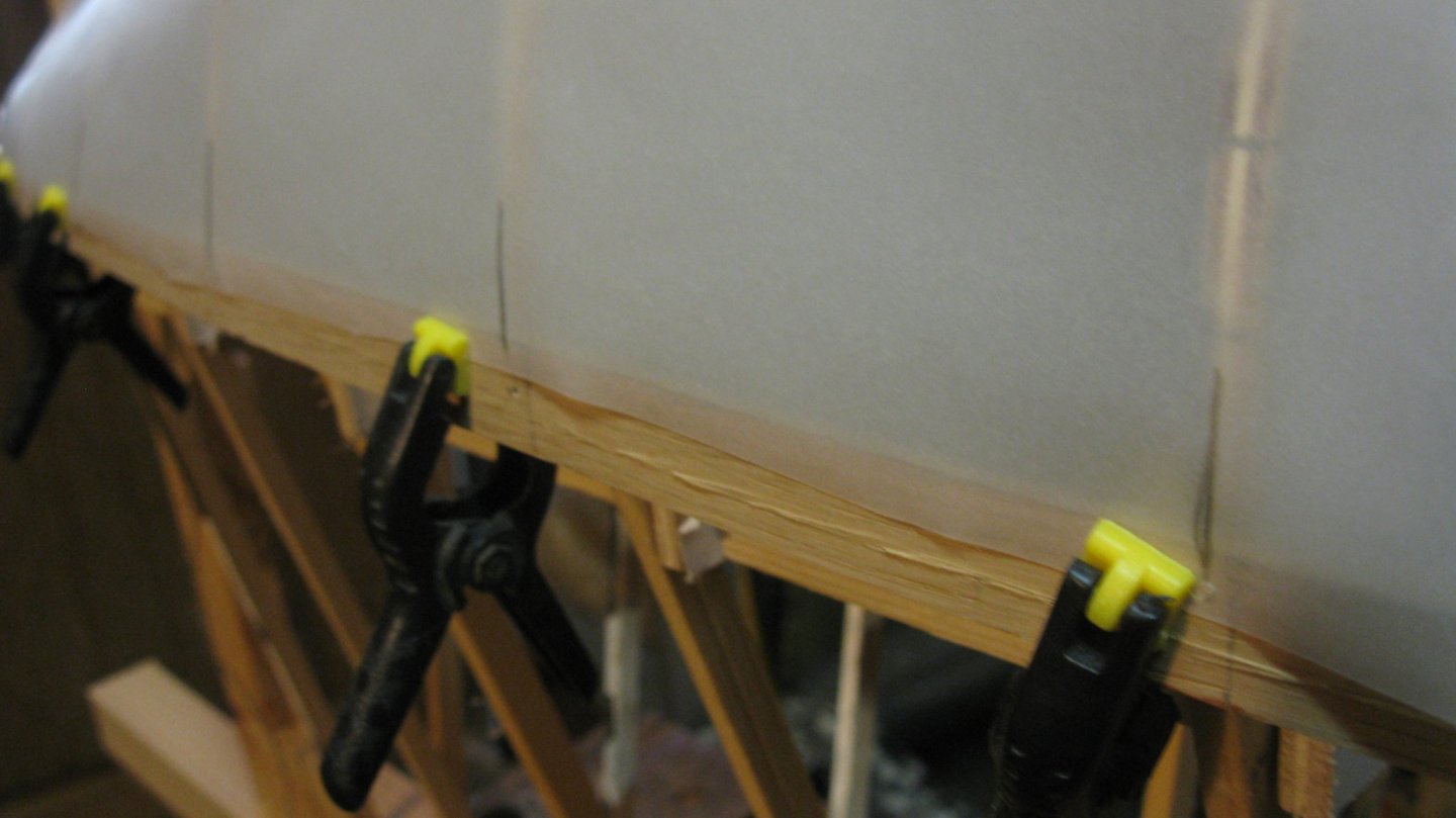
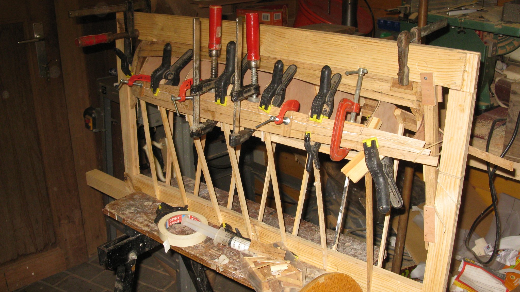
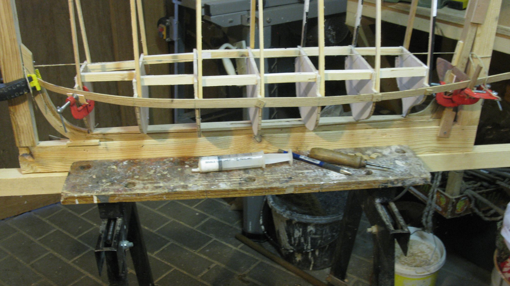
The plank glued and clamped.

Clamps removed the day after
Thank you to follow.
Thank you for the likes.
And thank you for the constructive comments.
Till next week!
-
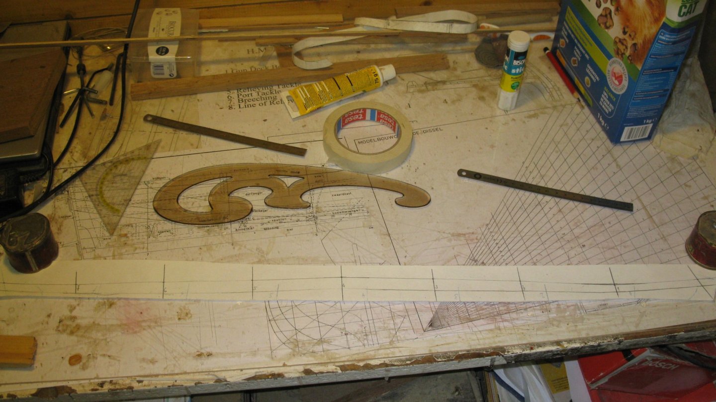
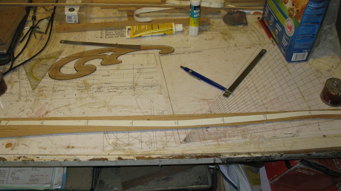
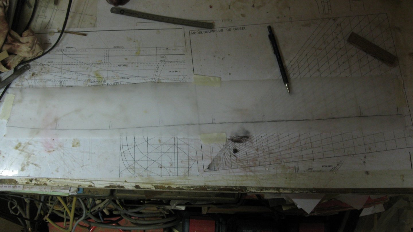
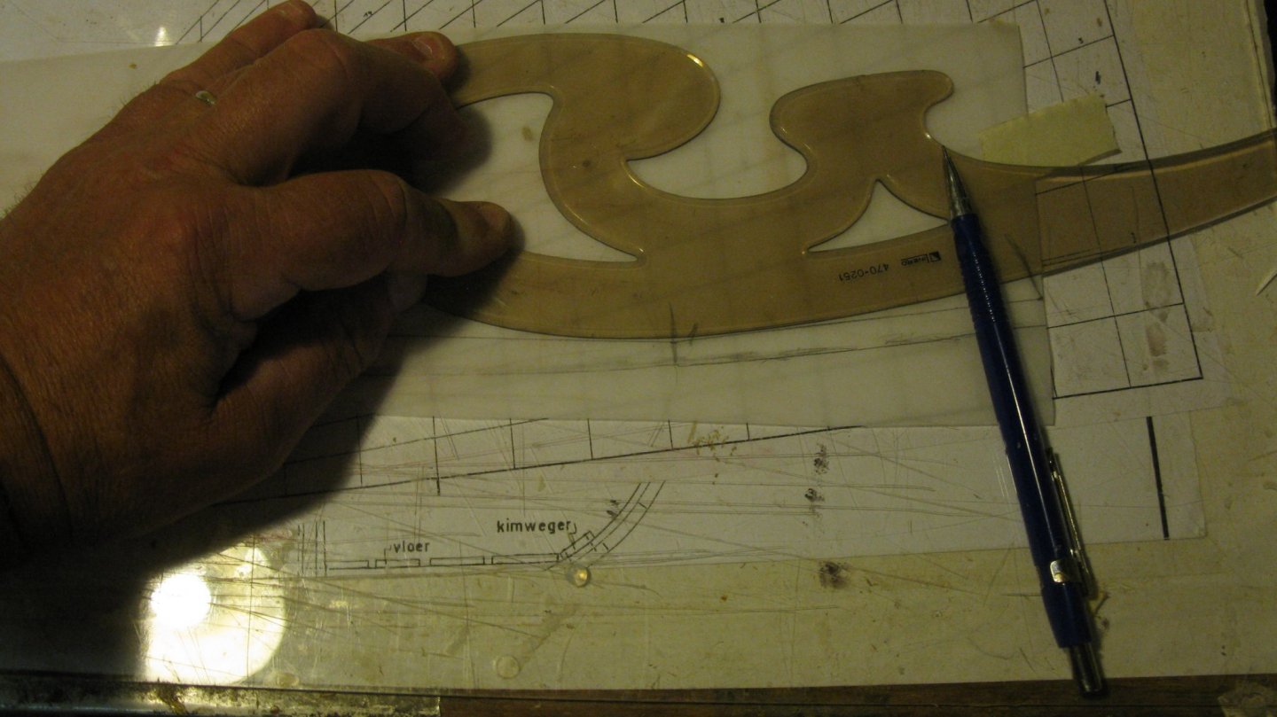
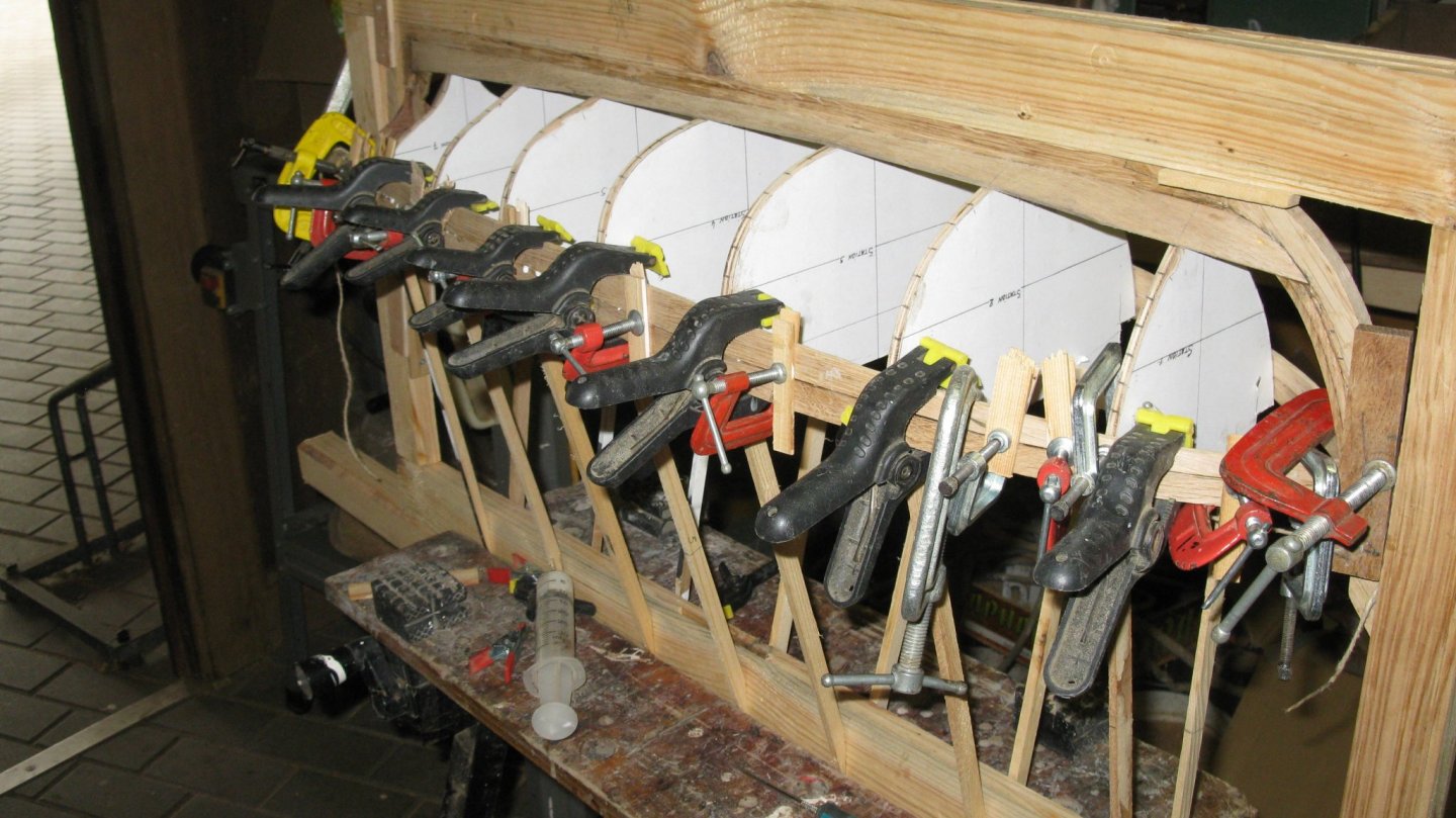
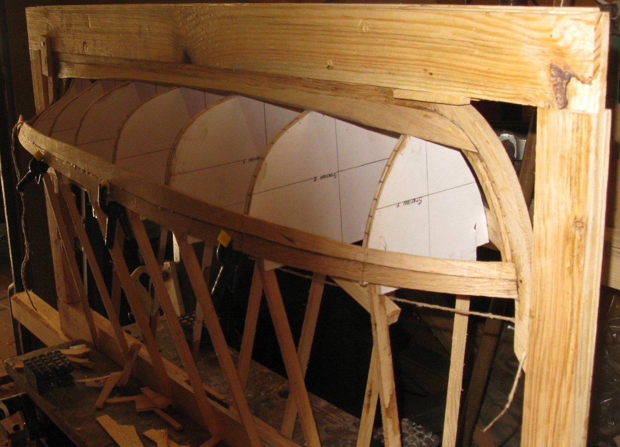
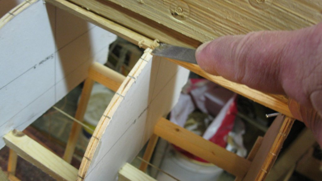
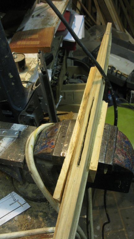
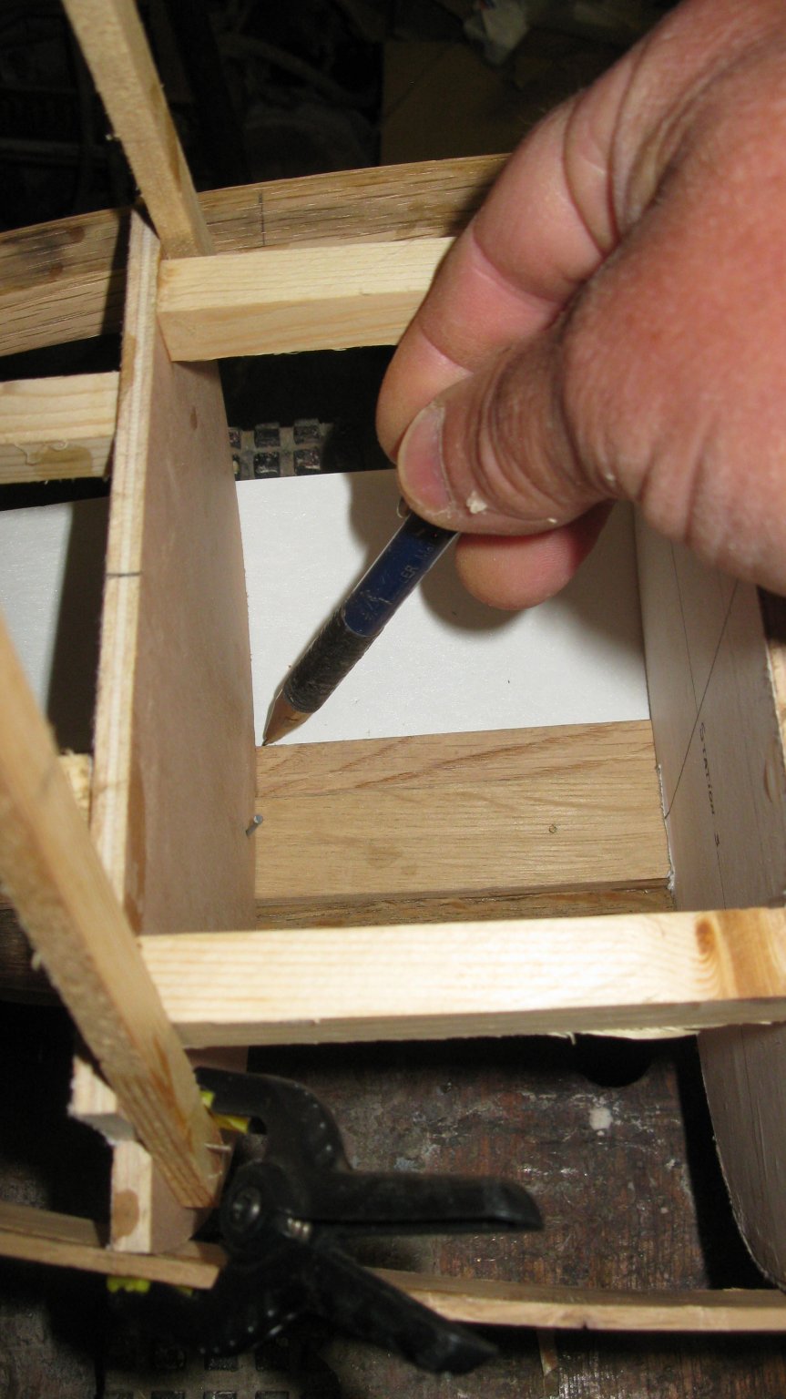
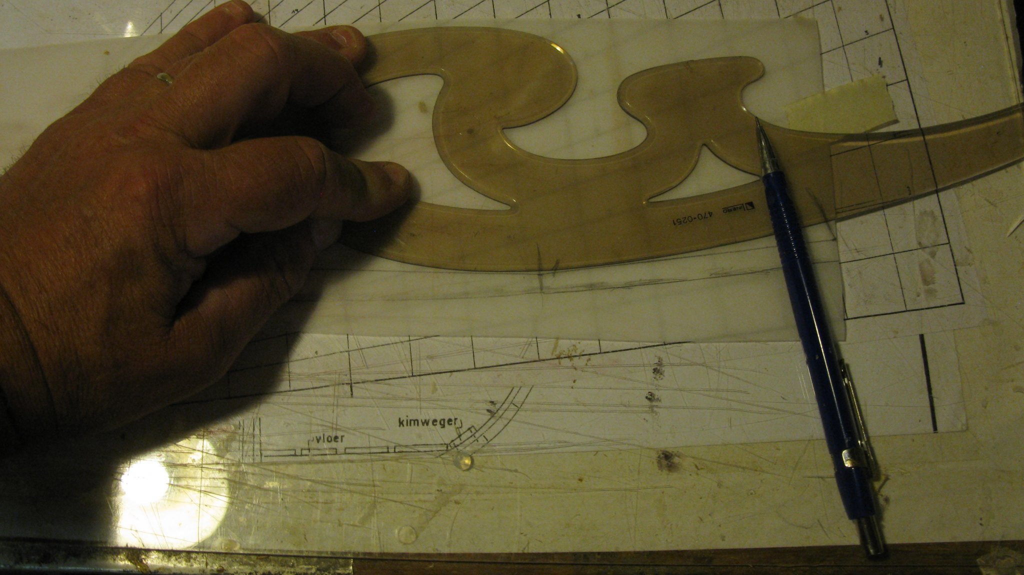
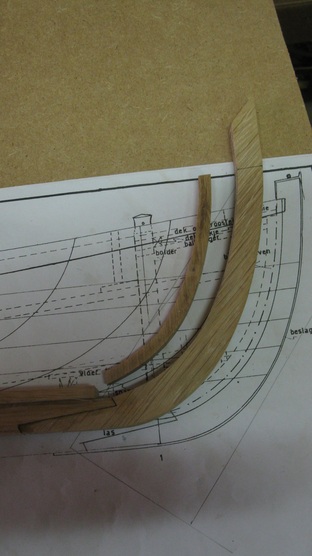
All the further strakes do not have one straight side, so from now on I will have to use an adapted method.
To determine the shape of the strake which is in place, I attach a strip of transparent paper to the model. The paper has to be attached as much as possible winkle-free.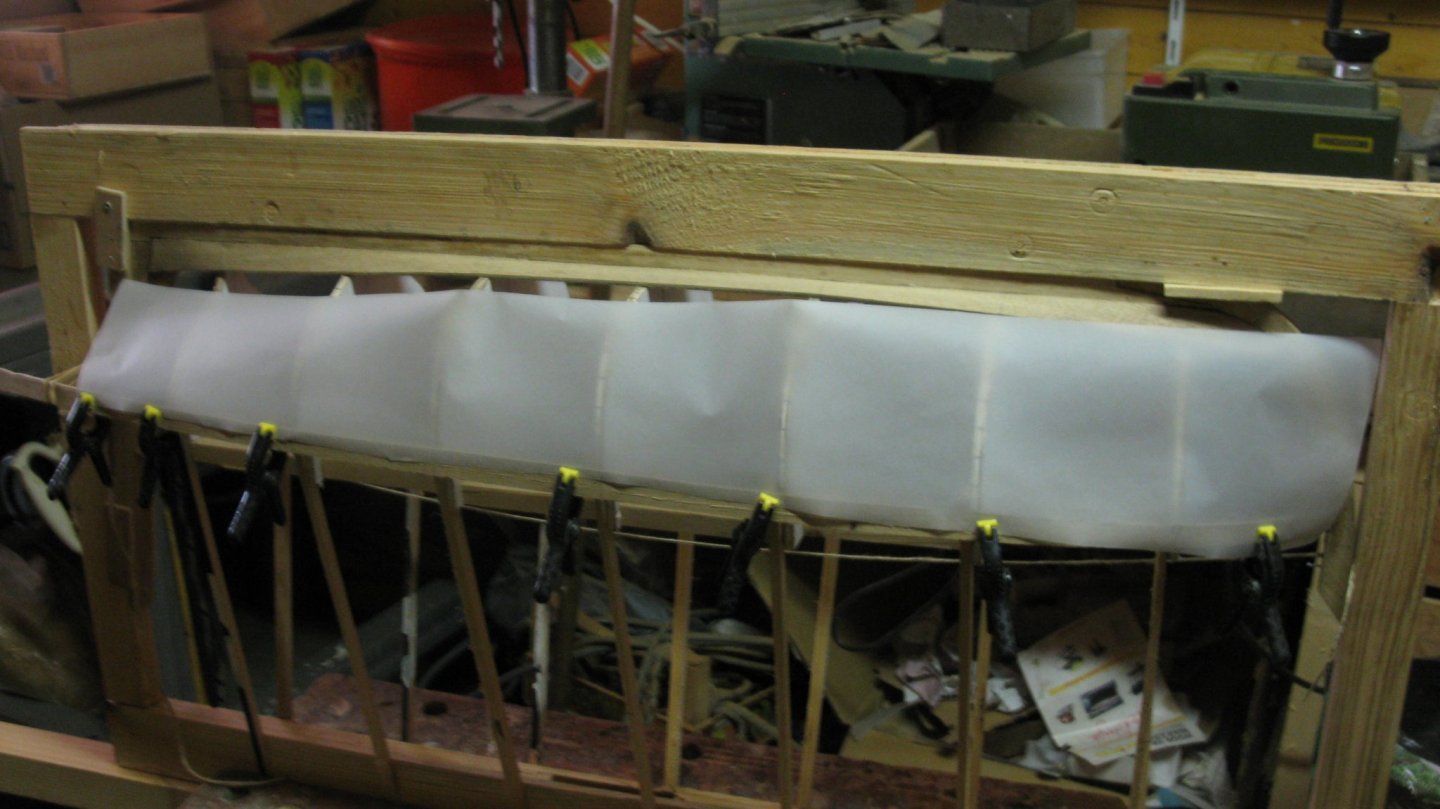
I mark the different stations on the paper.
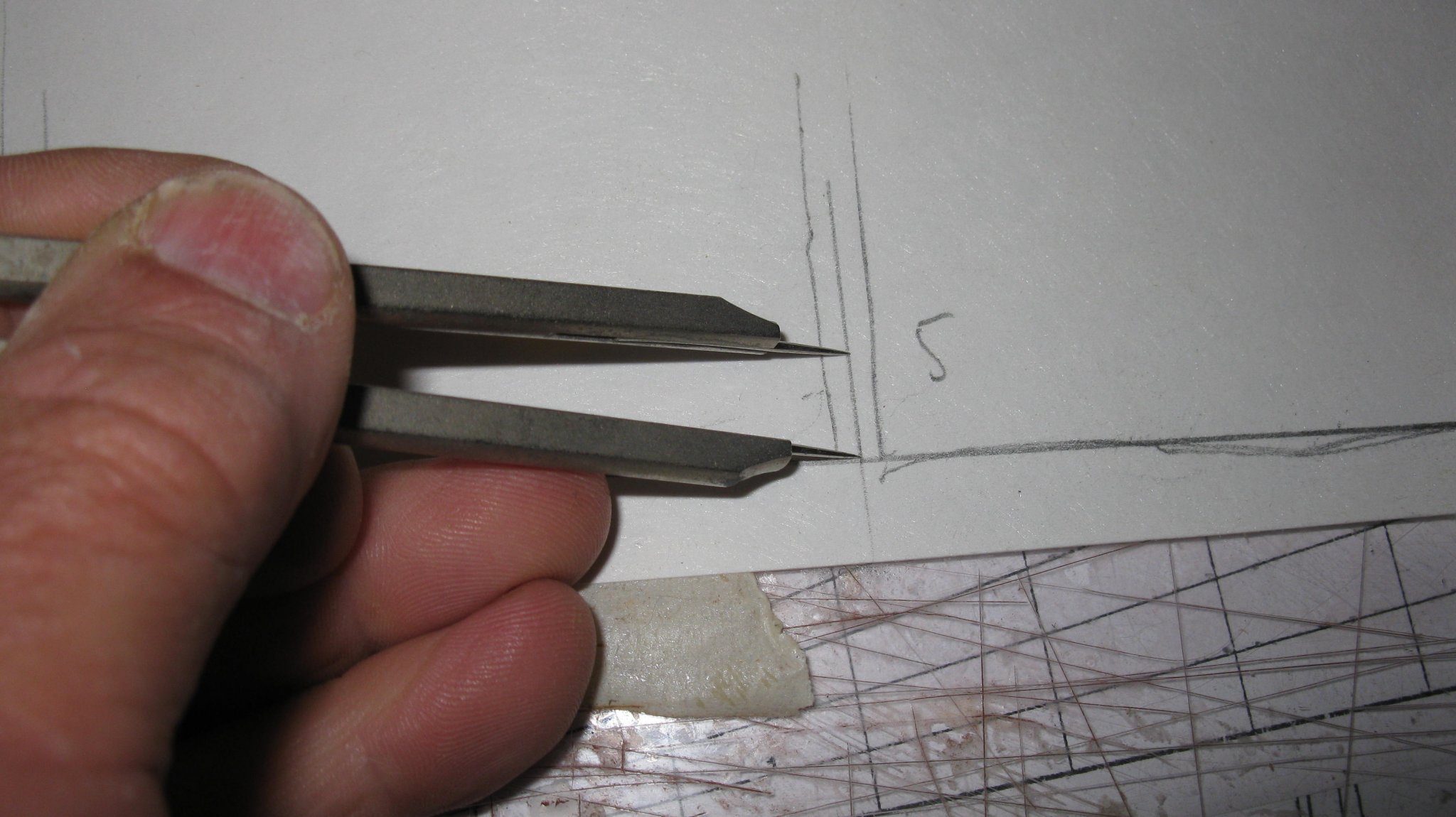
Now I rub with a pencil along the entire stake edge , that's how I get a sharp line of the plank side.
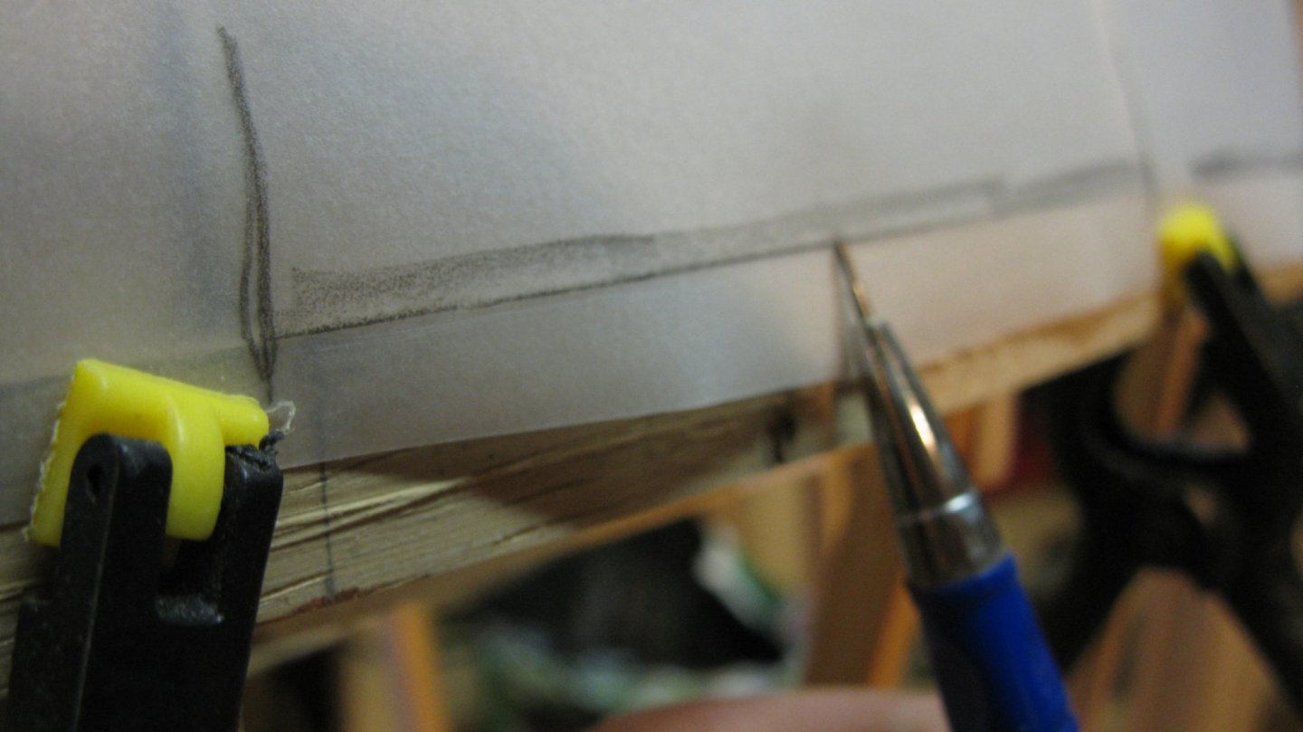
Now I take the paper off the model and measure station by station the width of the adjacent strake and mark them on the paper.

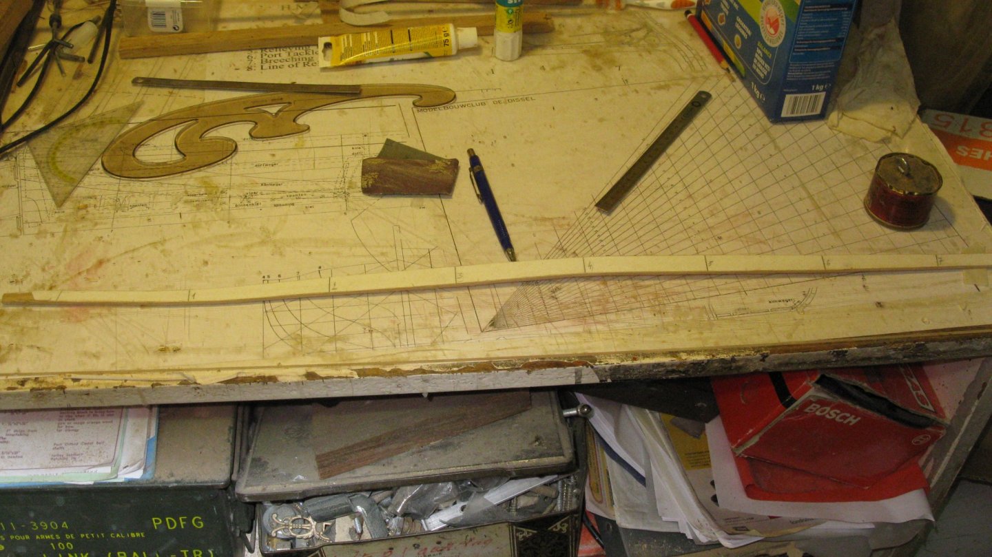
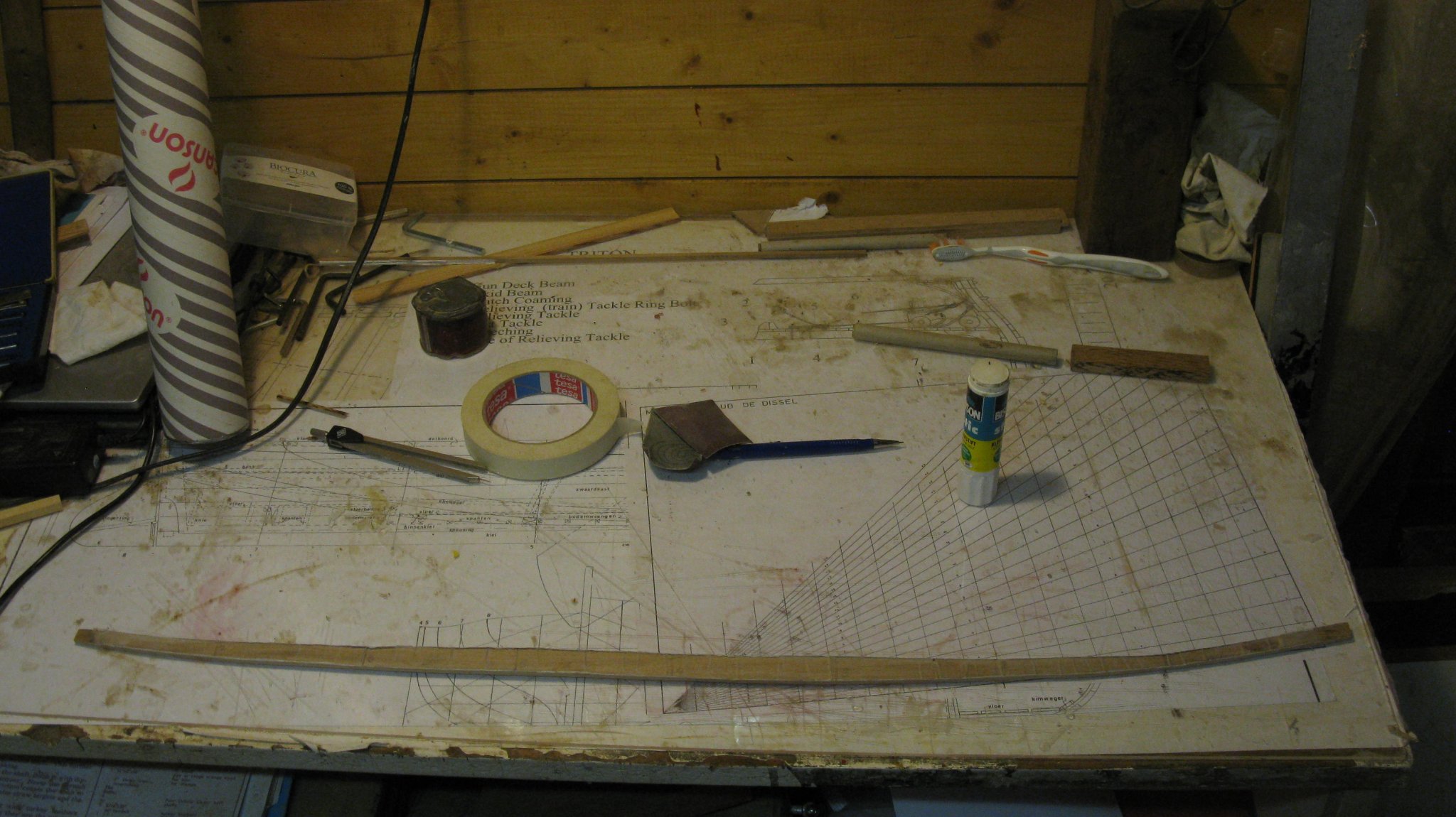
I connect all the markings with a continuous line. Where the connections are too angulated, I round them off. When all the is done I have a paper template of the strake which I glue on an oak plank to saw out and to sand into shape.

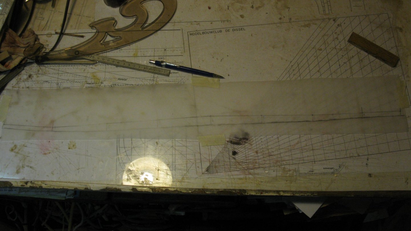
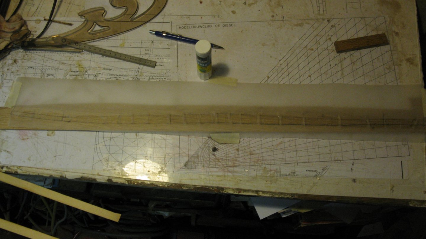
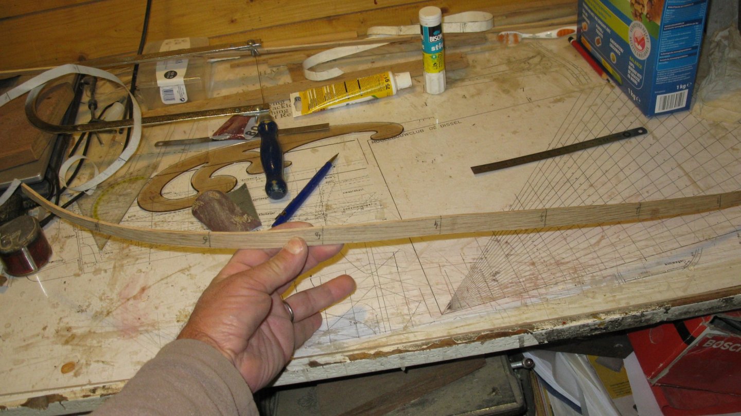
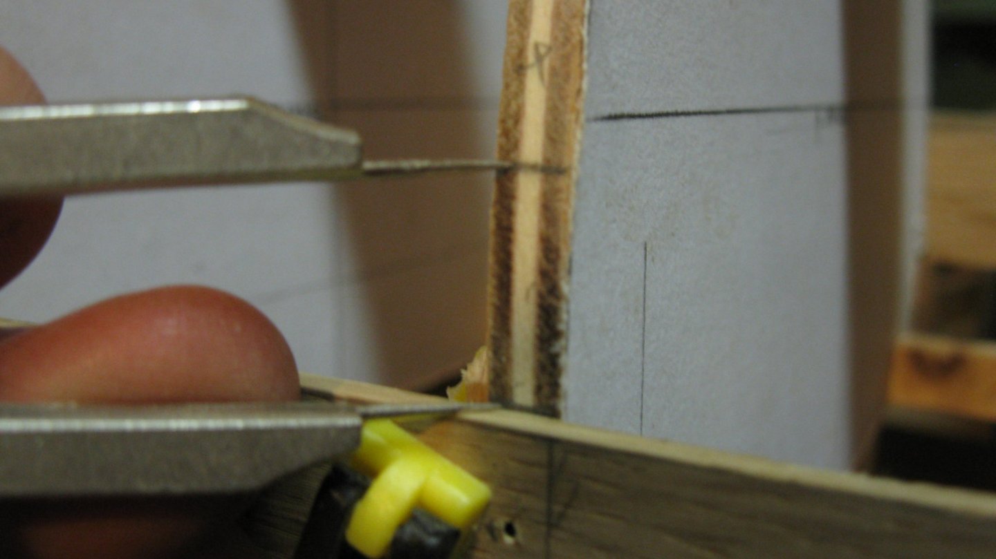
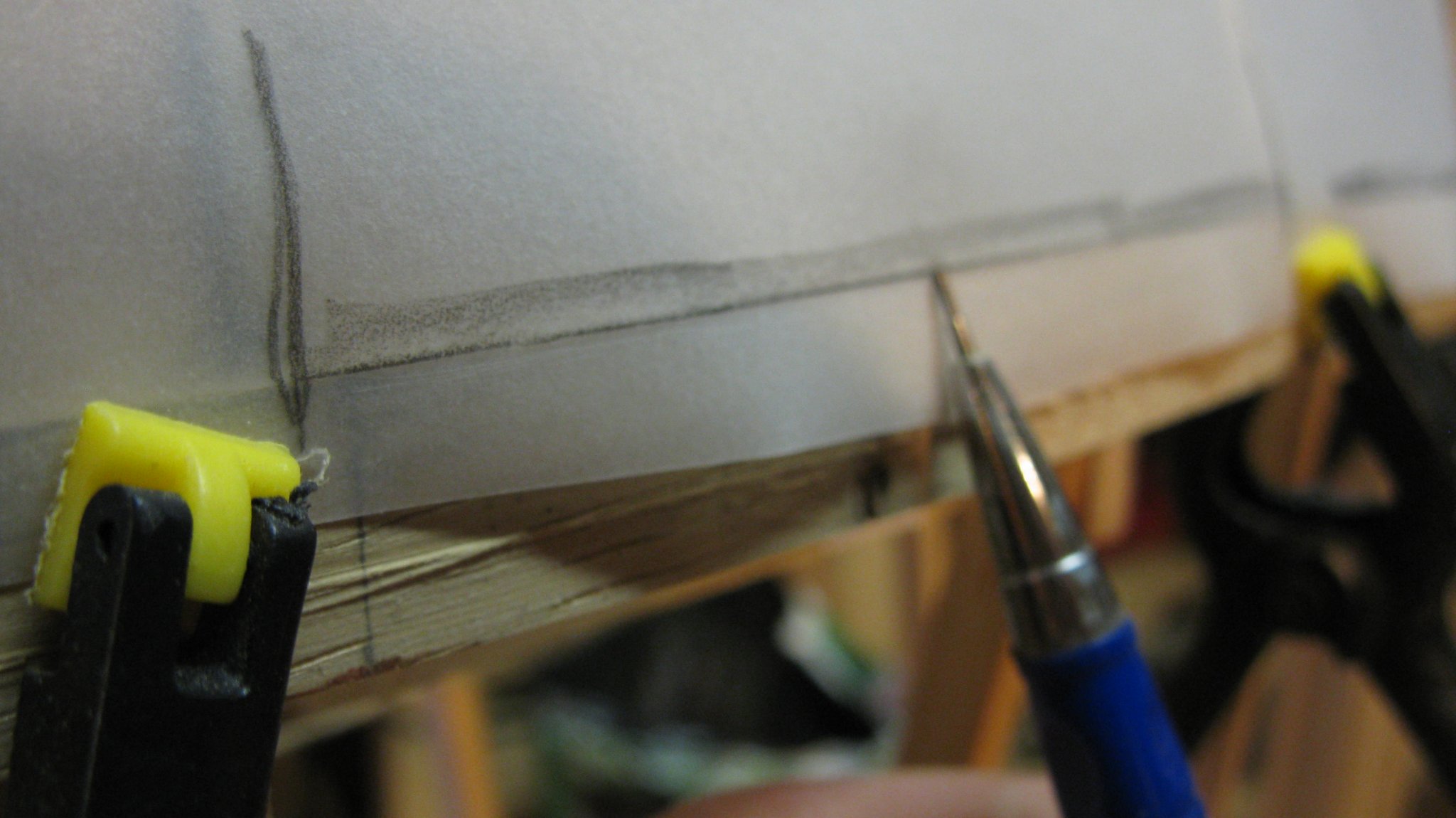
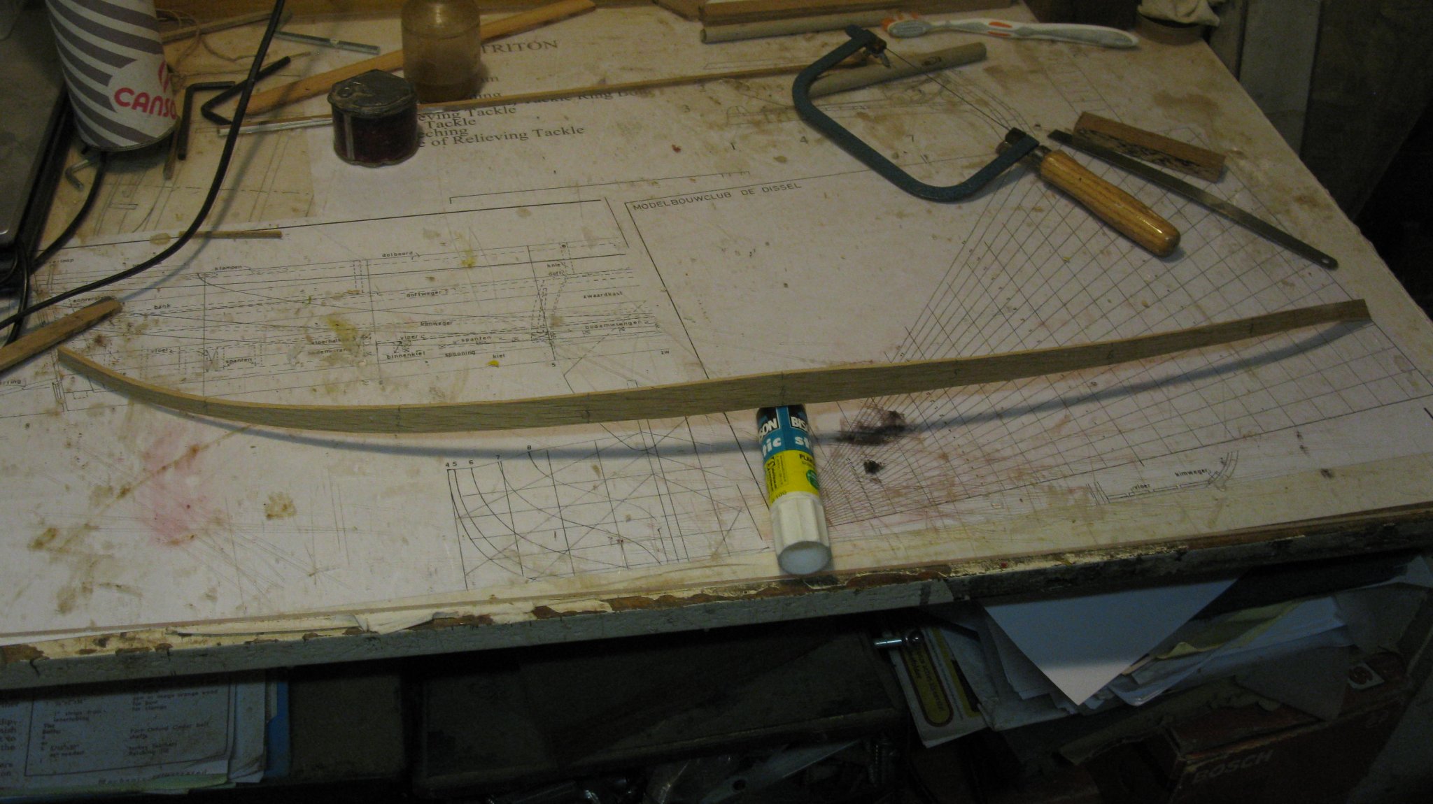
It is always a bit of surprise to see how the strake is bent. Here you see the strake sawn out and still with the paper template on it.

When peeling off the paper template, I take over the station markings on the plank to have a reference to place them on the model.
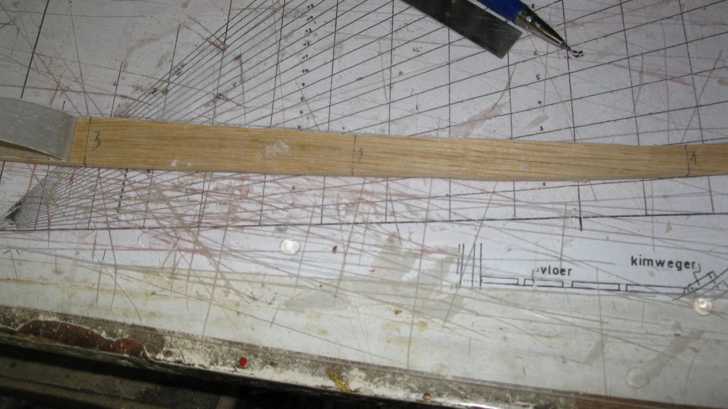
After a check to see that everything fits, I bend the plank (paint stripper heat gun method), ...

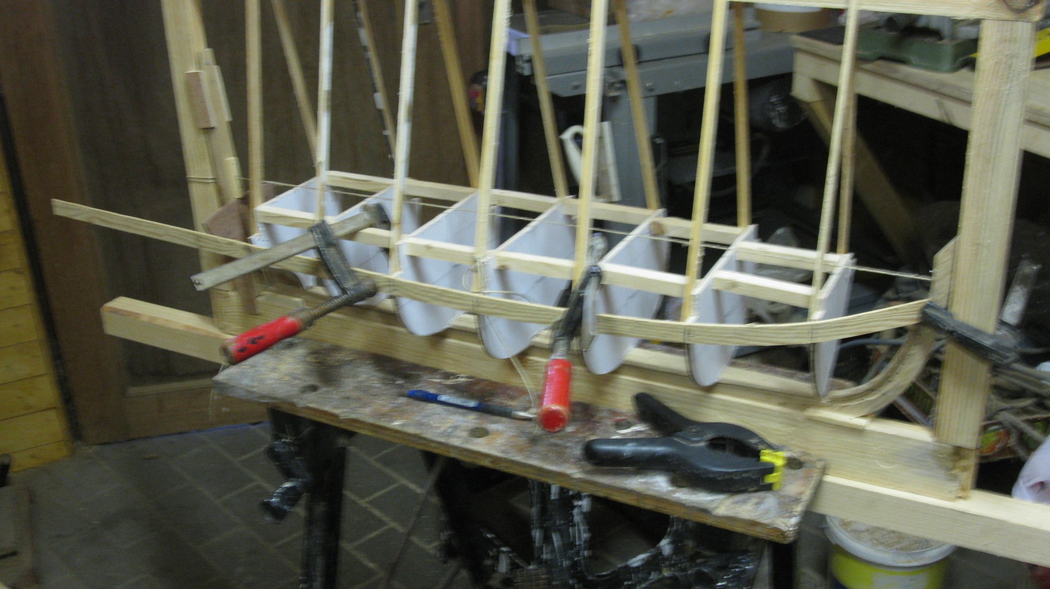
... glue and clamp the plank on the model.
-
12 hours ago, Mirabell61 said:
Thank you very much Geert,
is your gaff day boat sailor also going to be clinkered ?
Nils
No, it is carvel built.
-
Nils,
The water line looks very well done.
-
-
-
-
A really nice hull.
The captain looks very satisfied.
- pythagoras, mtaylor, ESF and 1 other
-
4
-
Quote
Svein Erik,
That is a very elegant Coast Guard cutter, a bit like a steam yacht.
I wish you much pleasure with the build of it and just signed in to follow.
- mtaylor, Nirvana and FriedClams
-
3
-
Indeed a very nice effect, Nils.
-
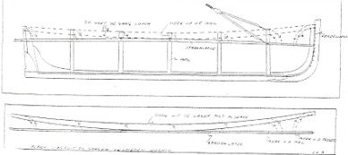
Part 4: Planking the hull
For me, an apprentice modeler, planking is still a hard nut to crack. Certainly in this model where the planks are 3 mm thick oak and uninterrupted from bow to stern.
Mr Van Byelen explains a method in his handout.
I have tried it out several times and was never able to make a workable plank, therefore I try to use the method by which I made the strakes for my schrimper.
As a non-English speaking it is difficult to explain it, but I will try to clarify how I work.
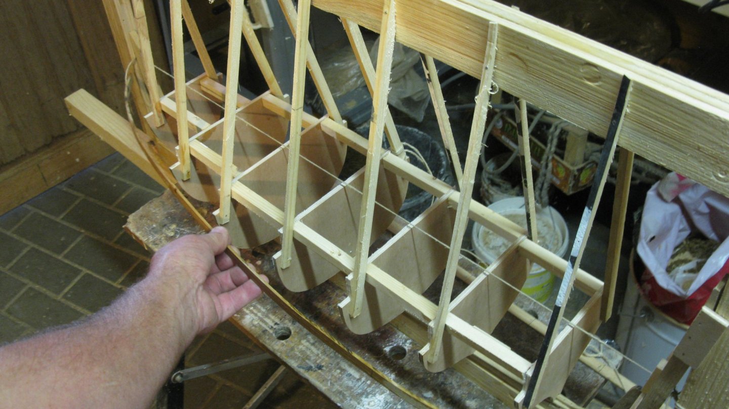
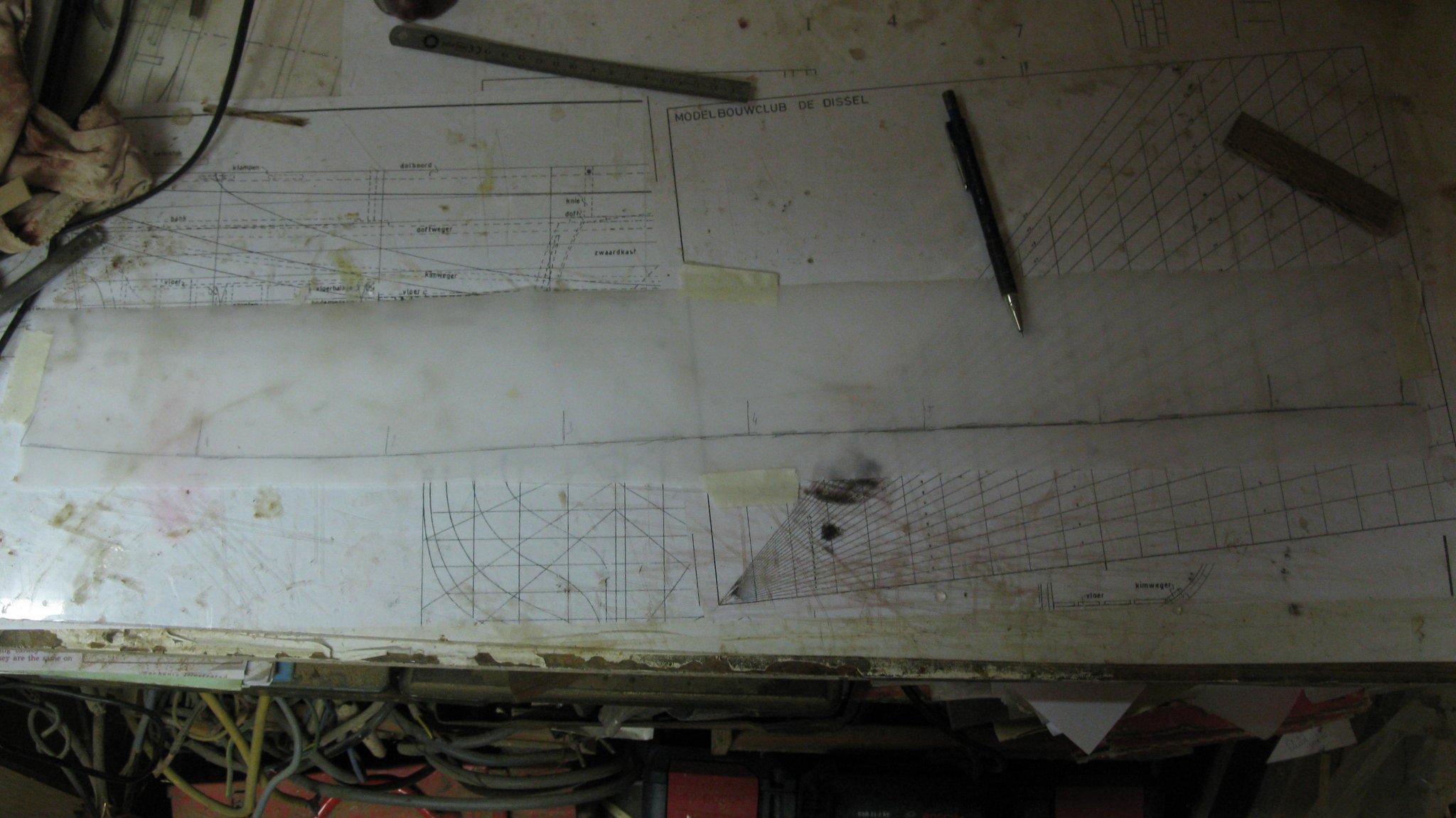
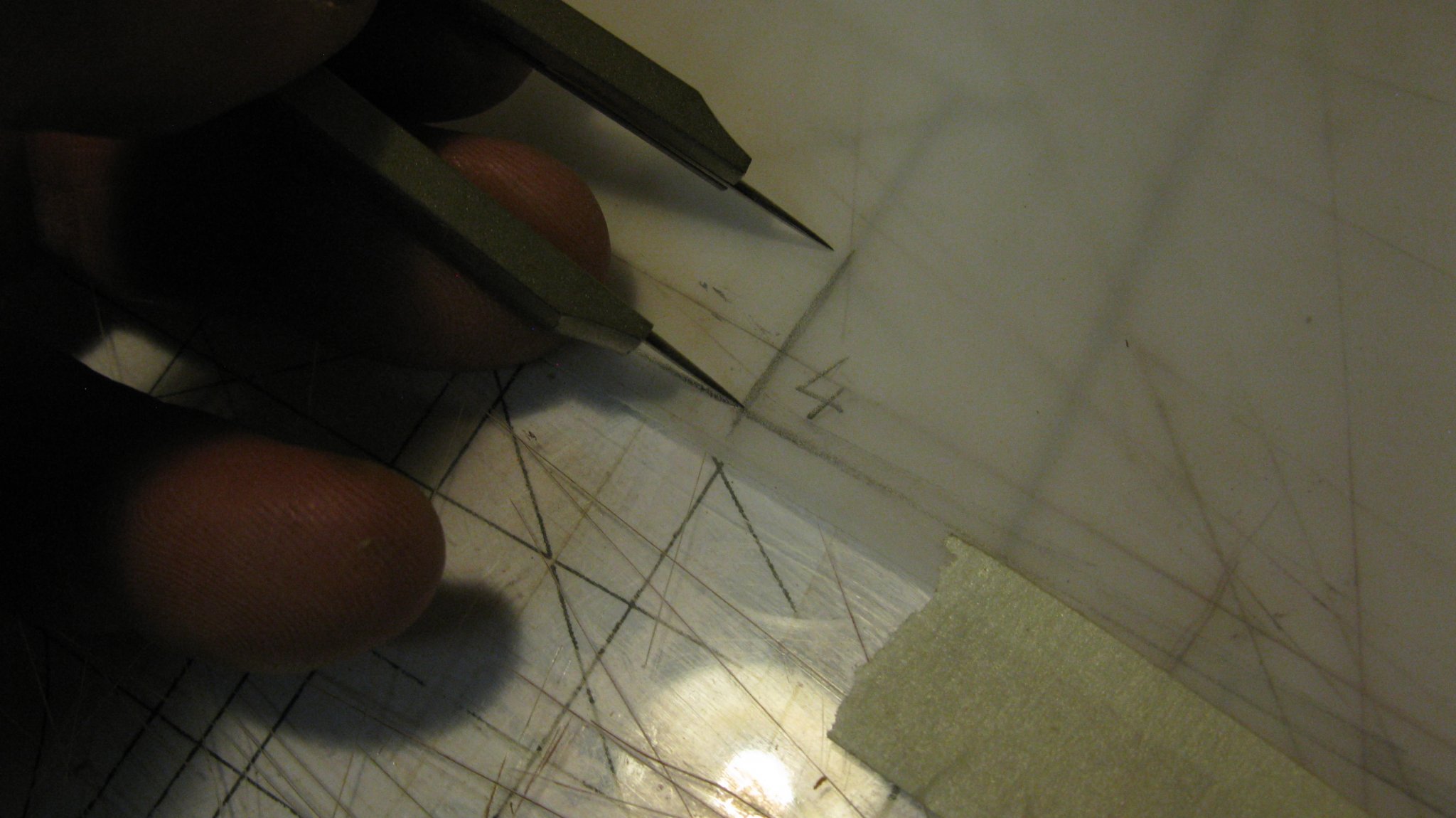
The model will have ten strakes on each side. I start with marking ten equal divisions on the side of each station.
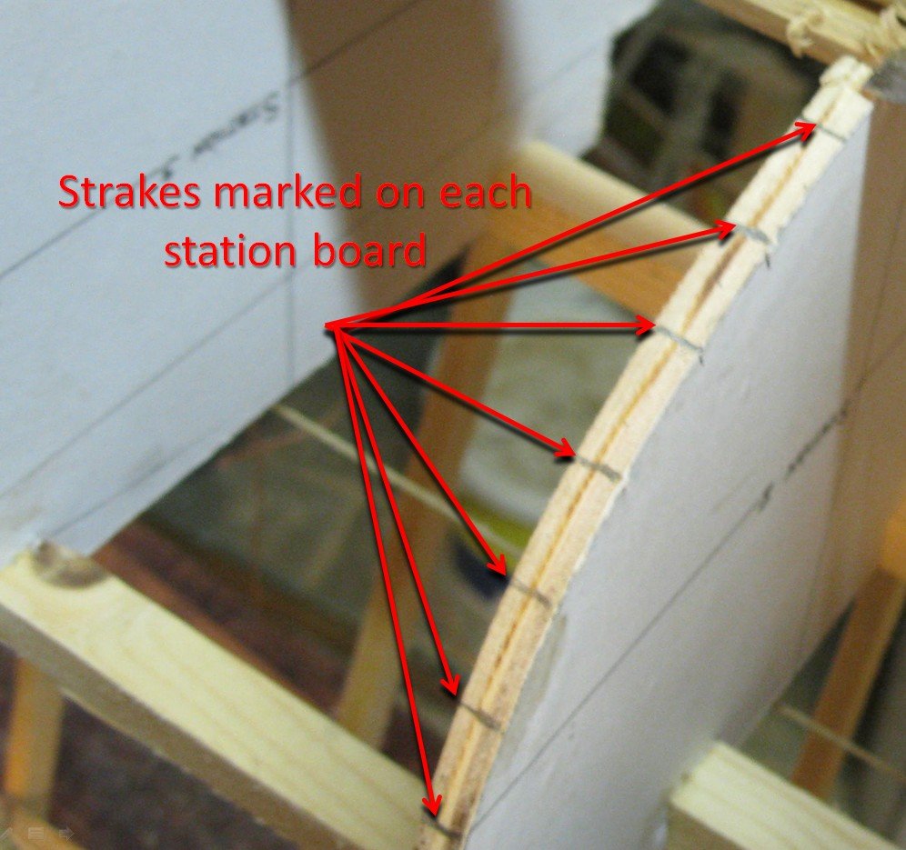
I presume that for the top (wale) and bottom strake (garboard) one side is straight, but as those strakes run convex over the stations they do not stand perpendicular on those straight sides and despite their mutual distances are equal on the keel, they are not on the curved strake.
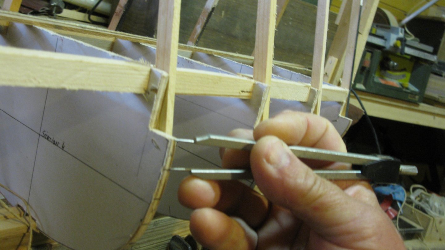
To determine those vertical station angles and their distances on the surface of the hull, I clamp a straight lath around the stations with the upper side equal to the tops of the stations and mark the vertical direction of each station (unfortunately the picture is a bit hazy).

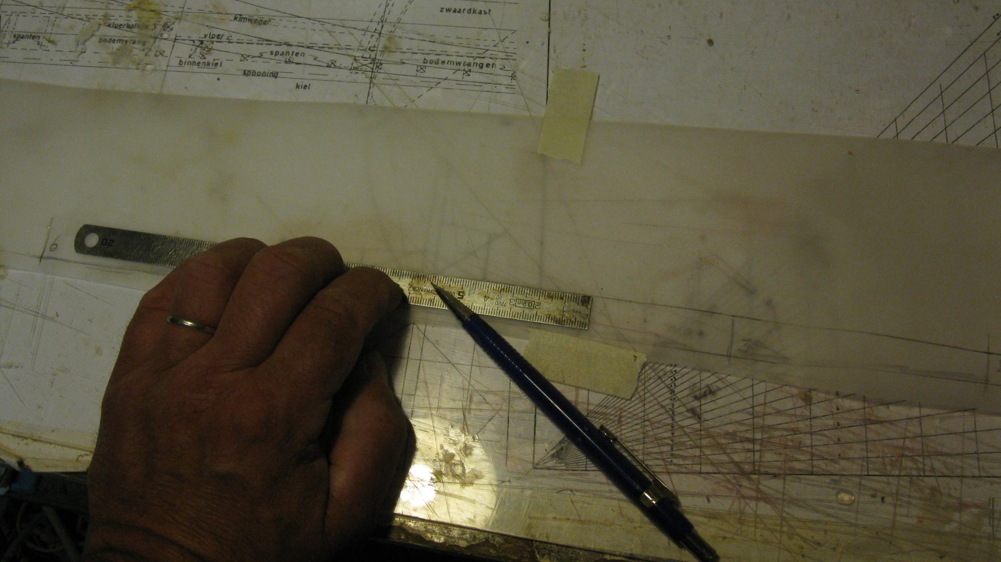
I take over the station positions and angles on the plank from which I will saw the strake.
Next thing to do is measuring the strake with on each station and bring it over to the respective markings on the plank.

I saw and sand the plank and I attach it provisionally to the model to check the shape.
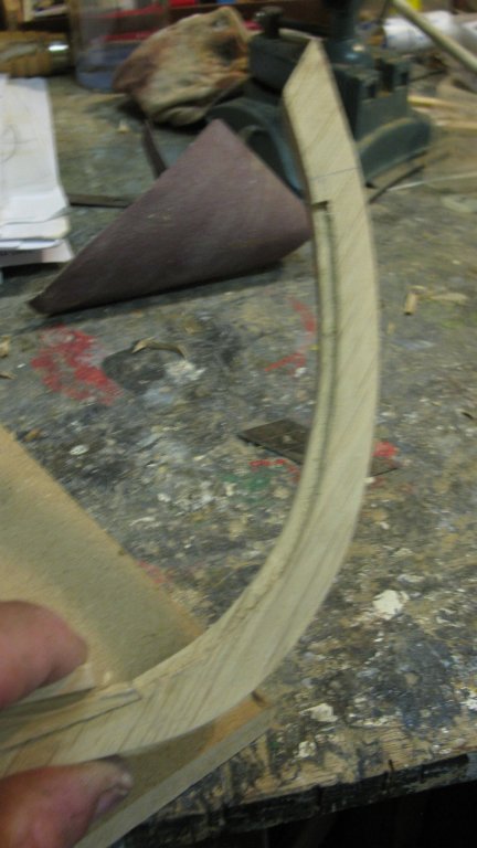
When all last corrections have been made, the strake must get her curved shape. Therefore I wet the plank and bend it over the heat of a candle flame. After this heat treatment the strake keeps her curved shape...
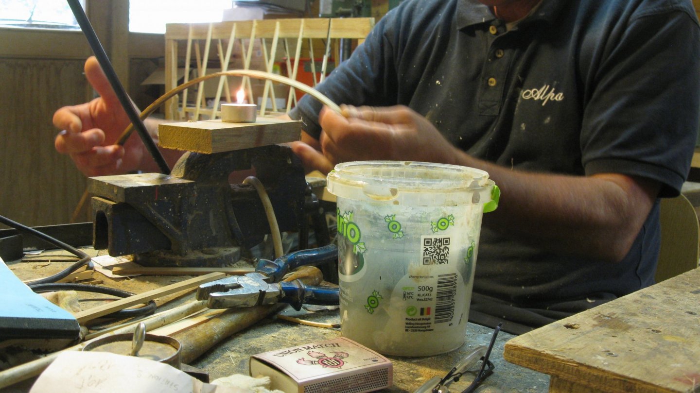
... and can be attached to the model.

Next day day it's up to the other side.
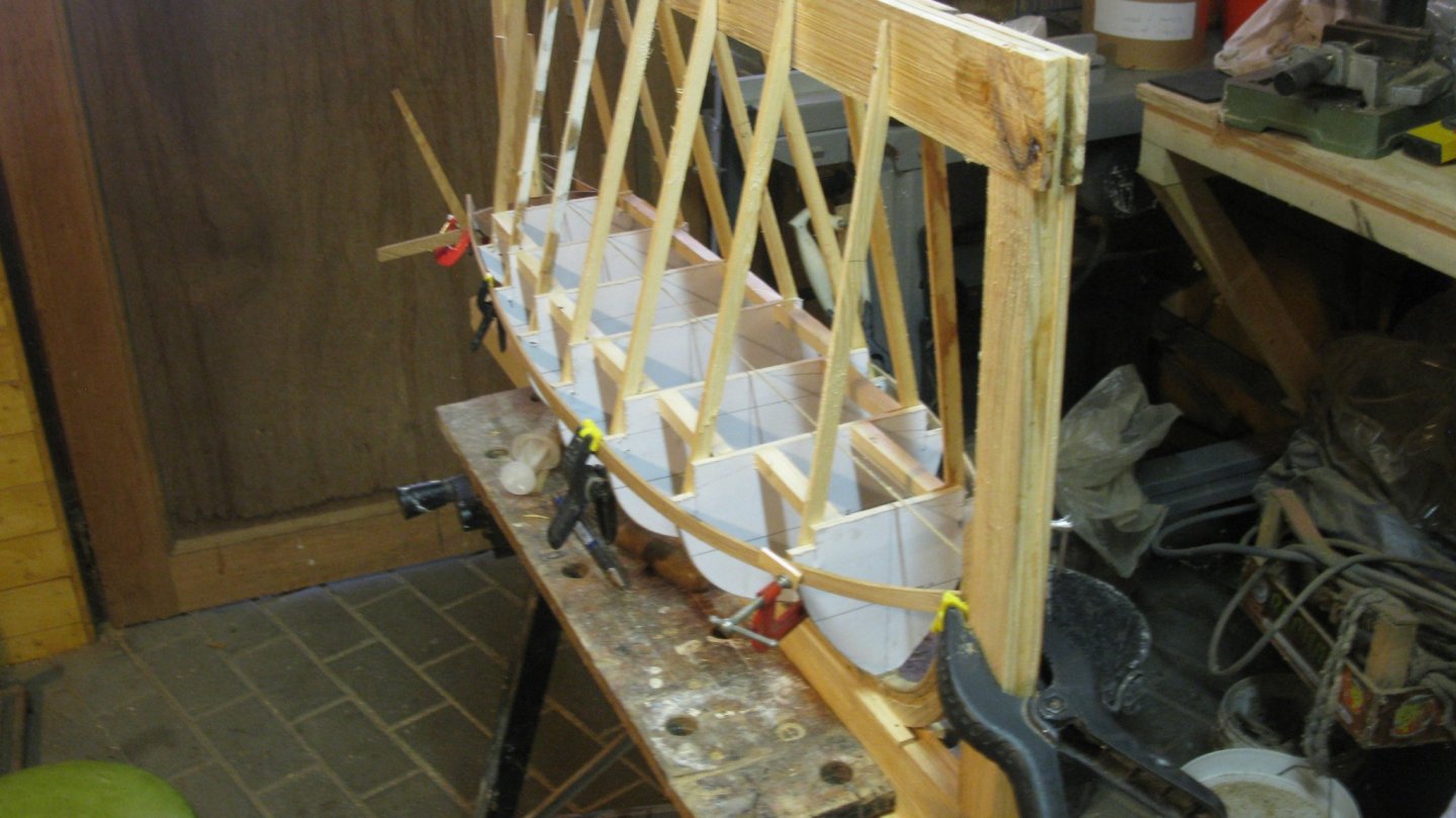
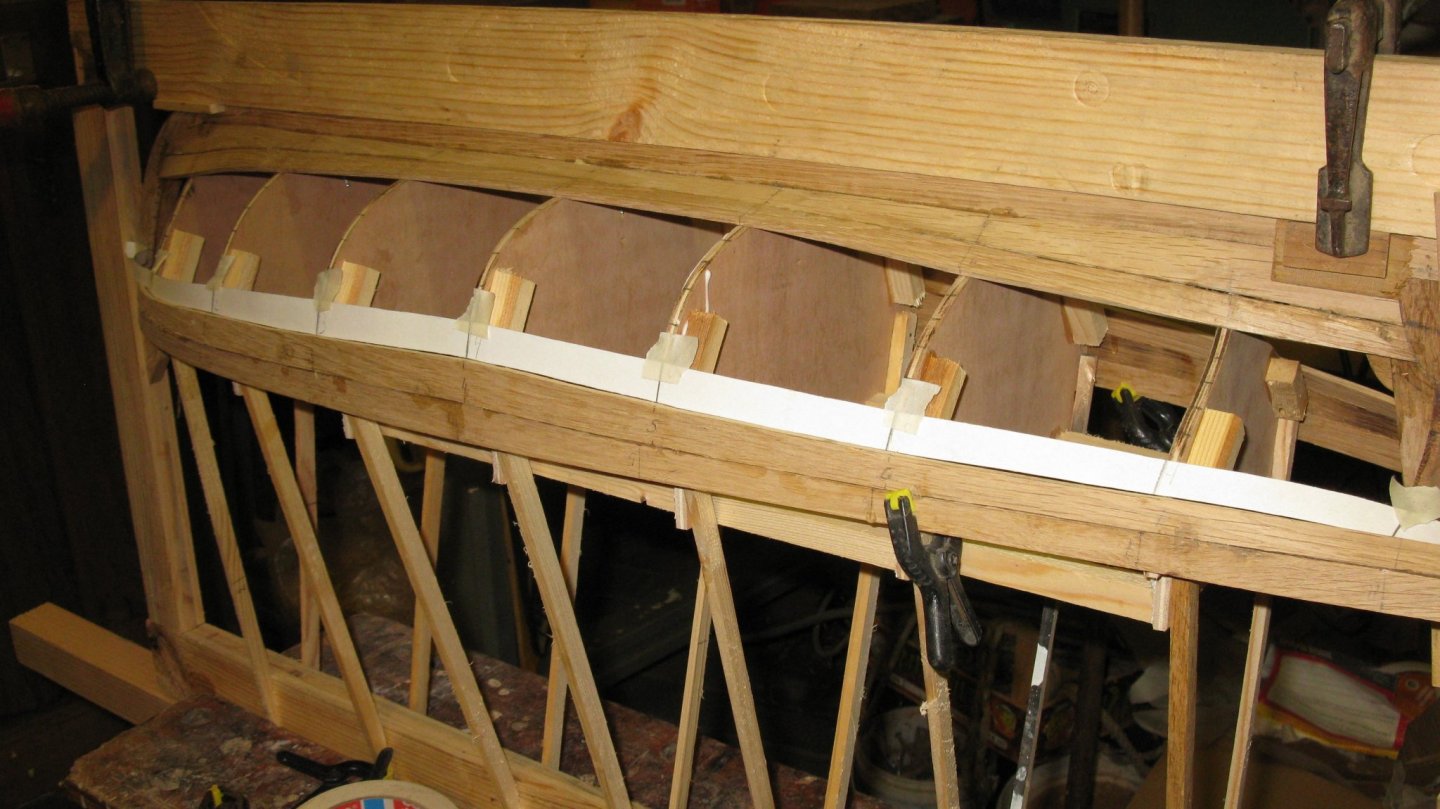
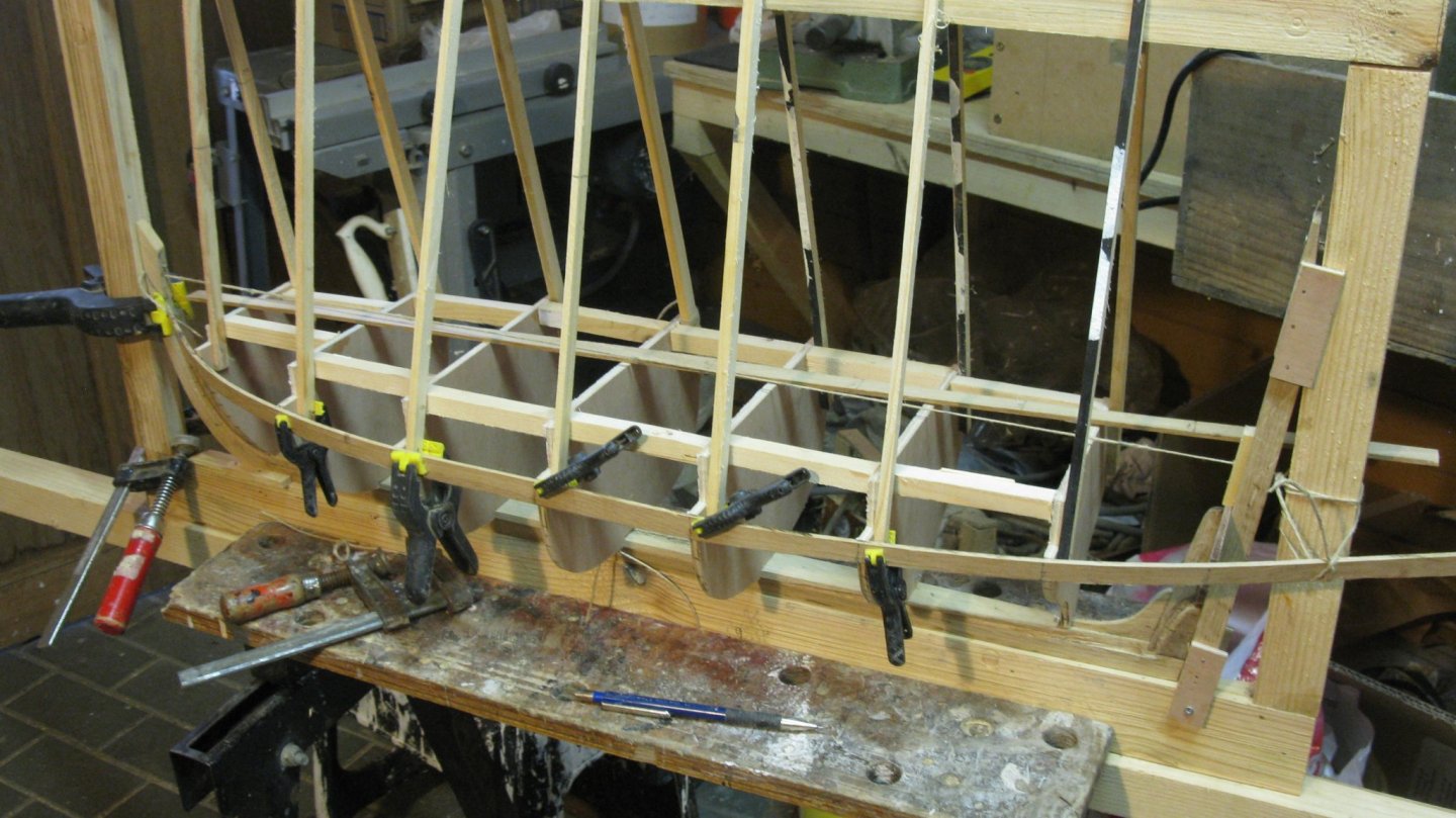
The two wale strakes are now in place. They are only glued at the bow and the stern and are therefore very fragile.
Now I will place the garboards. It is a similar procedure as for the wale strakes. They have also a straight side were they lie against the keel.
I try another system to bow the planks. This time I bow them dry above a paint stripper heat gun. It works a lot faster and better than a candle flame.
The starboard garboard...
... and the port one.
All the further strakes do not have one straight side, so from now on I will have to use an adapted method. But that is for next post.
Thank you to follow.Thank you for the likes.
And thank you for the constructive comments.
Till next week!
- Baker, GrandpaPhil, hexnut and 7 others
-
10
-
-
Alexander,
You accomplished a splendid work. Your log was a real pleasure to follow. I learned a lot of it, thank you very much.
Your boeier model is a masterpiece!
- Keith Black, mtaylor and Jack12477
-
3
-
On 8/24/2019 at 12:26 AM, Heinrich der Seefahrer said:
Highly intertsting methods of work and excellent craftmansship you do show to us, Thanks for sharing!
Thank you very much, Heinrich
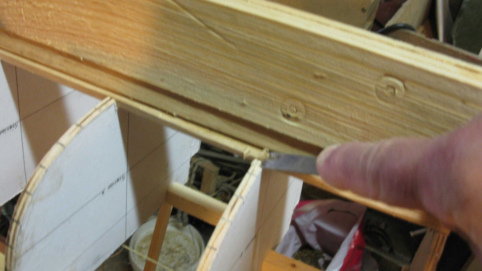
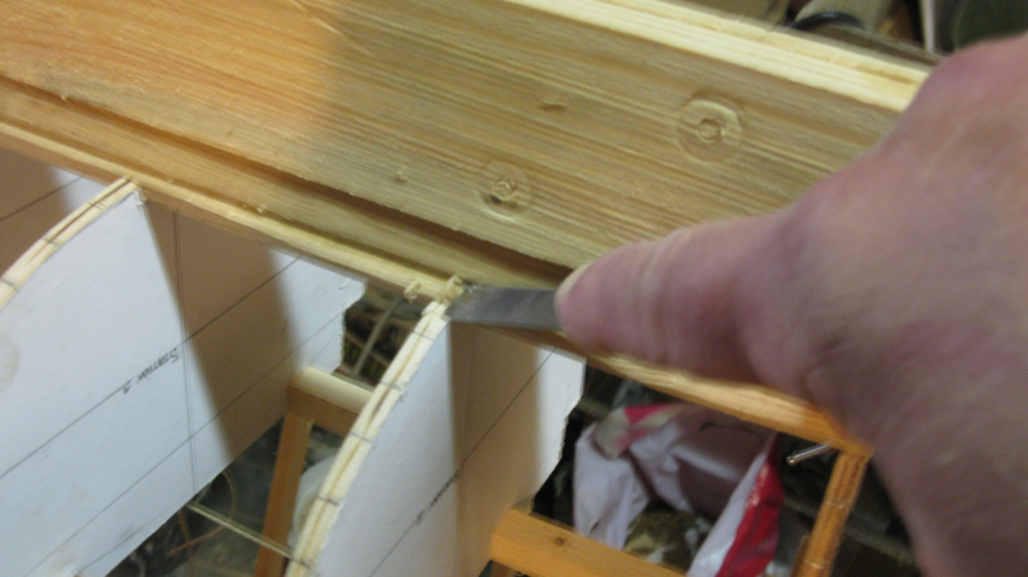
On 8/24/2019 at 12:54 PM, Peter Cane said:I like the building frame. Genius idea.
Could you show some more pictures of the Garboard strake notch please as I have to learn how to do this.
The model will be fantastic.
I like your choices of wood too.
Thanks.
Pete
Thank you for the complements Pete.
I searched on my memory card for more pictures, but they show all a bit the same. The problem is that this is a retroactive log and that the shown construction stadium dates from about a year ago. The hull is now planked and the garboard notch is filled, it is not possible anymore to make more pictures of it.
At the time I probably failed to make a picture of the notch in its totality. Using the chisel with one hand and making a picture with the other is sometimes an awkward operation.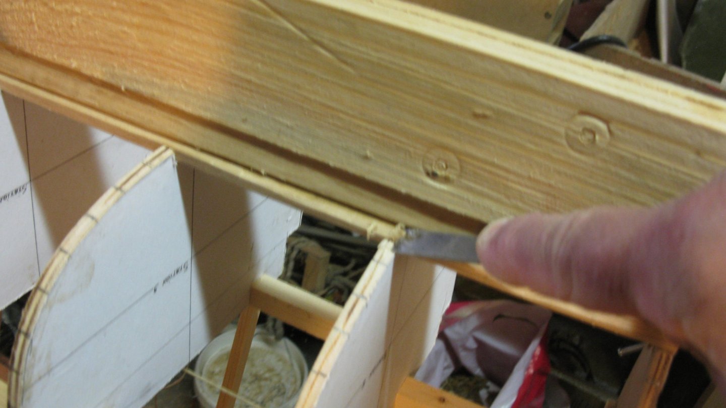
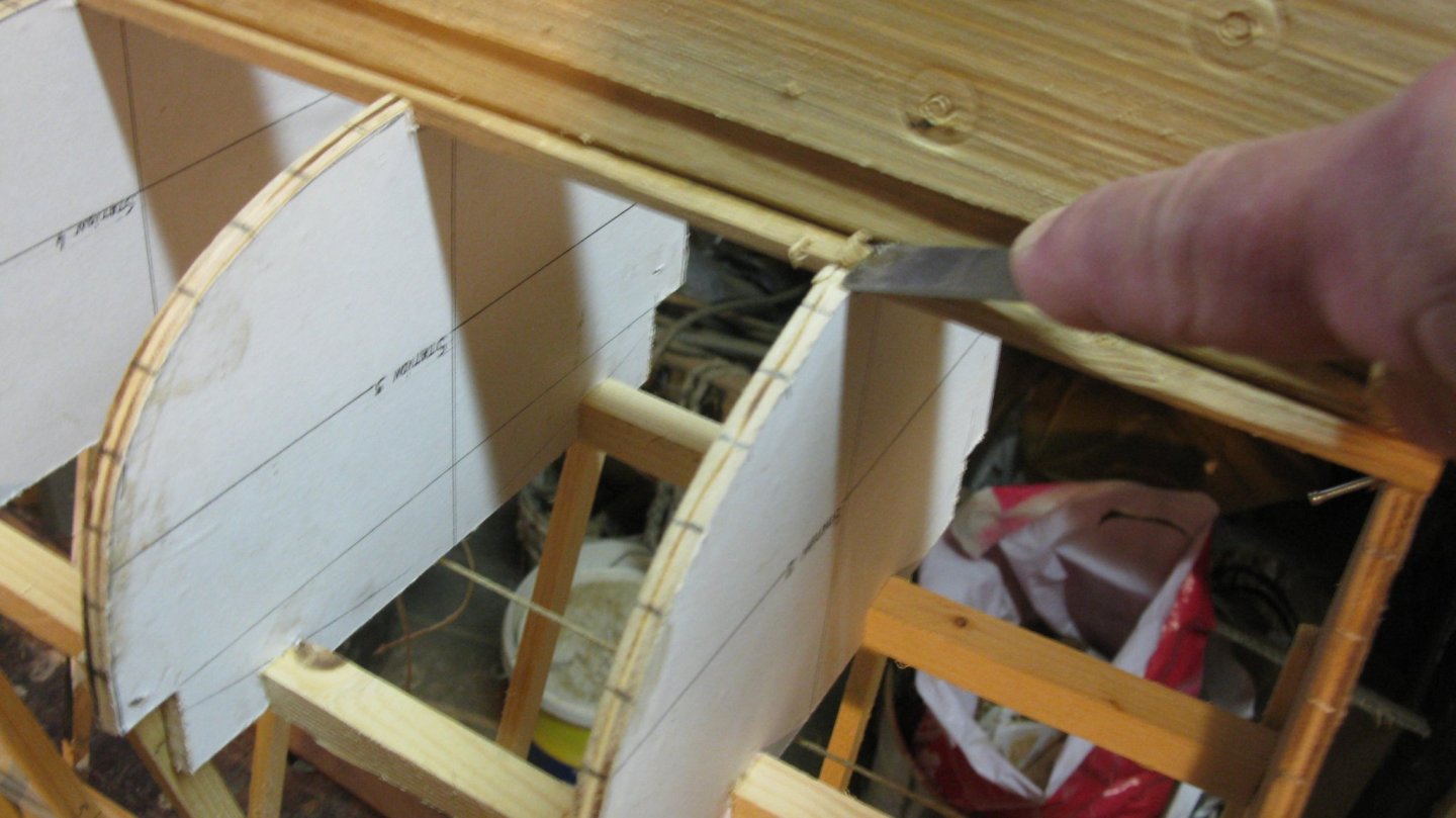


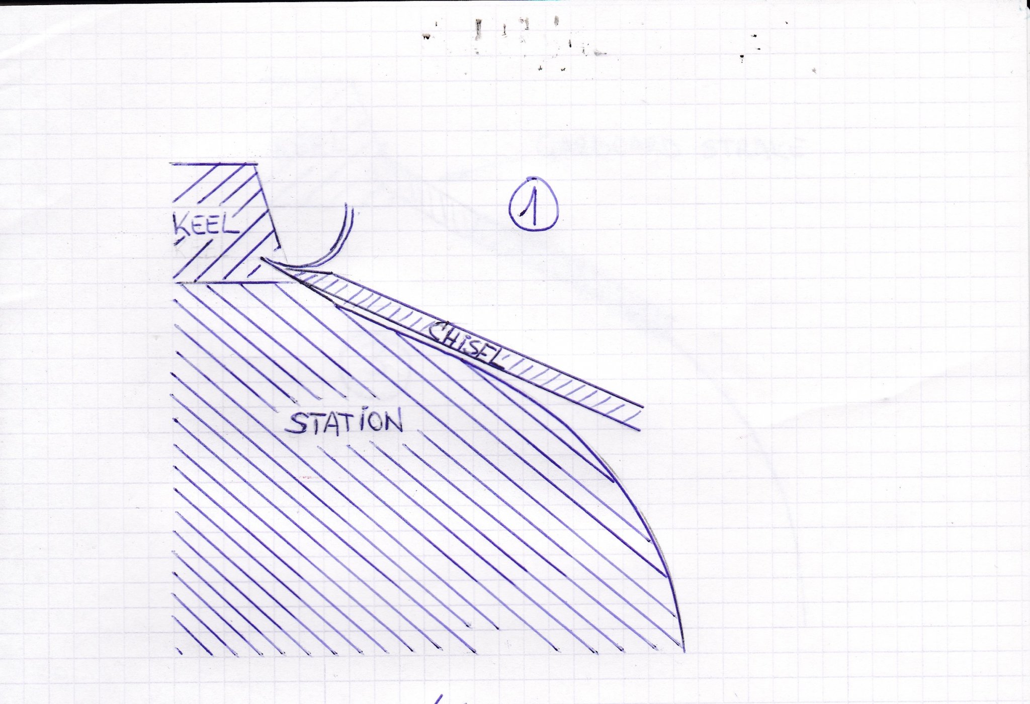
The principle is as follows: At each station there is a possibility to check the shape of the garboard notch. The vertical cut with the chisel has to follow as much as possible the direction of the station edge (sketch 1) and the horizontal cut of the chisel must be as much as possible perpendicular to the vertical cut (sketch 2). That means that the shape of the cuts are slightly different from station to station. Between the stations the notch has to be cut in a way that the shape transitions happen gradually.
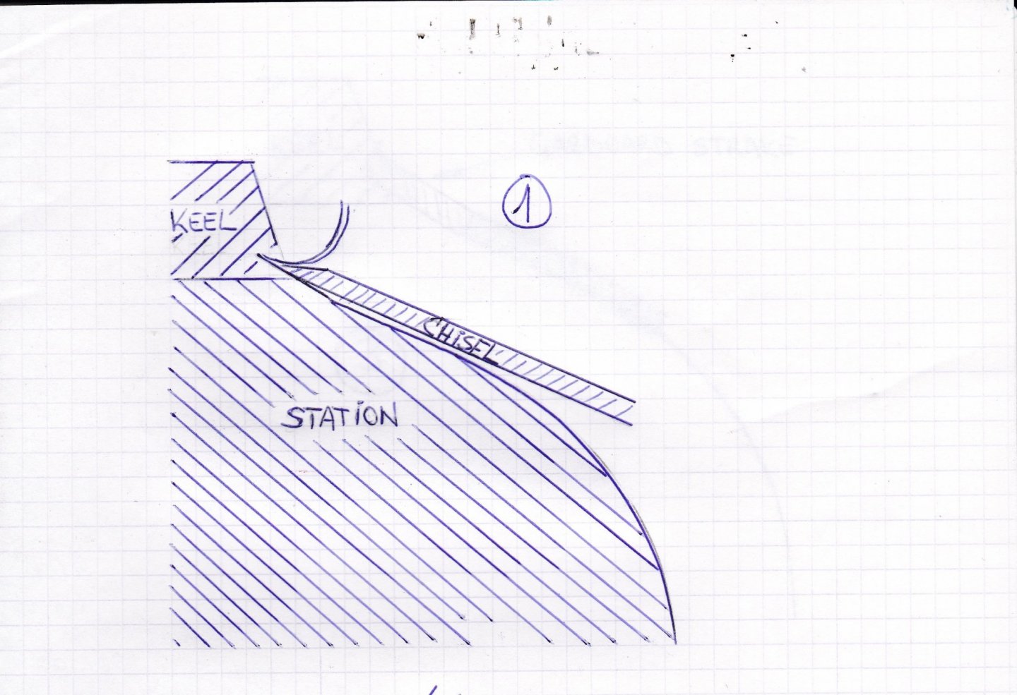
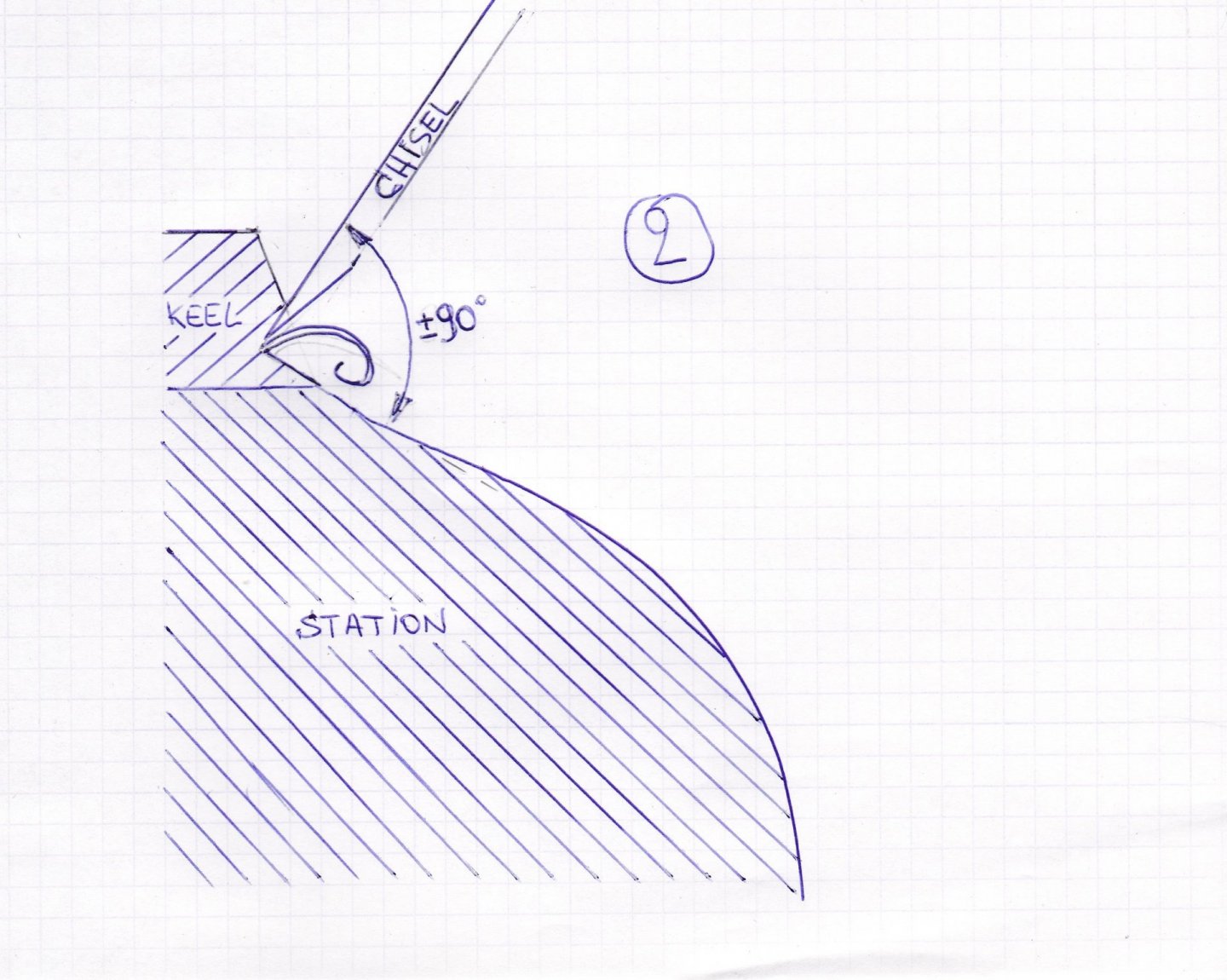
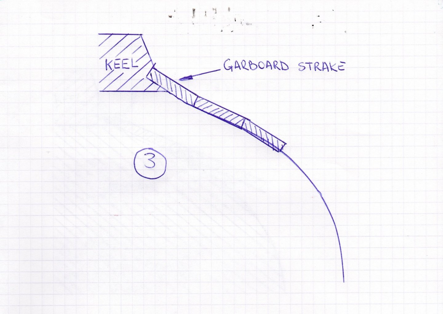
The garboard strake has to fit in the notch along the whole length of the keel (sketch 3).
-
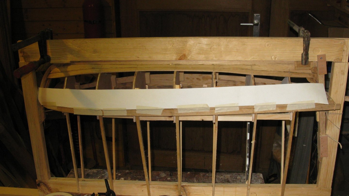
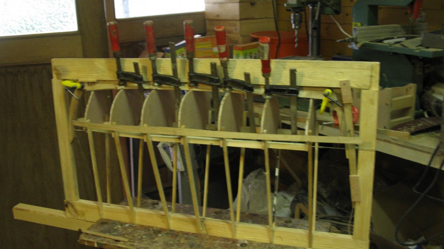
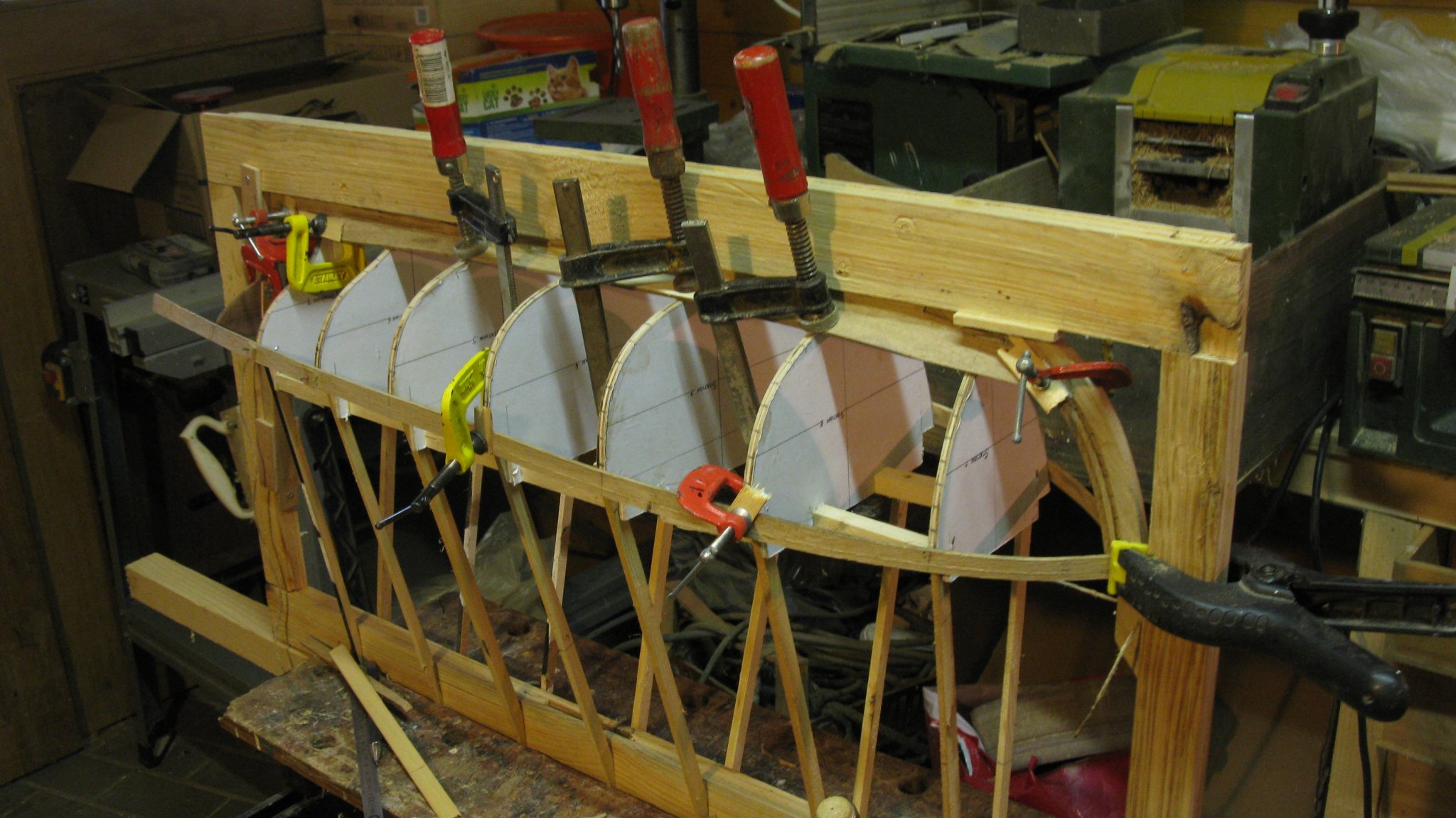
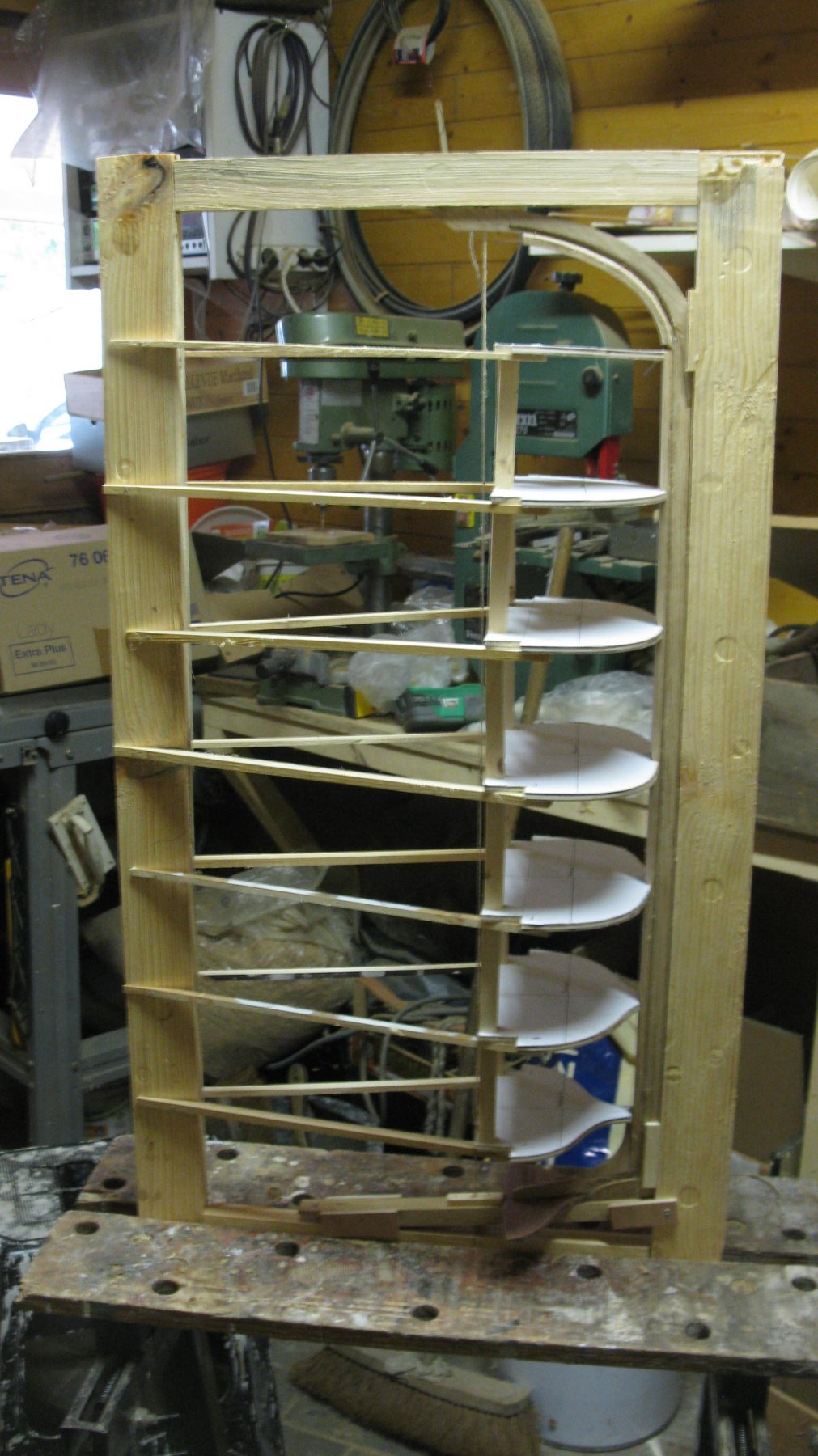
Part 3: The building board
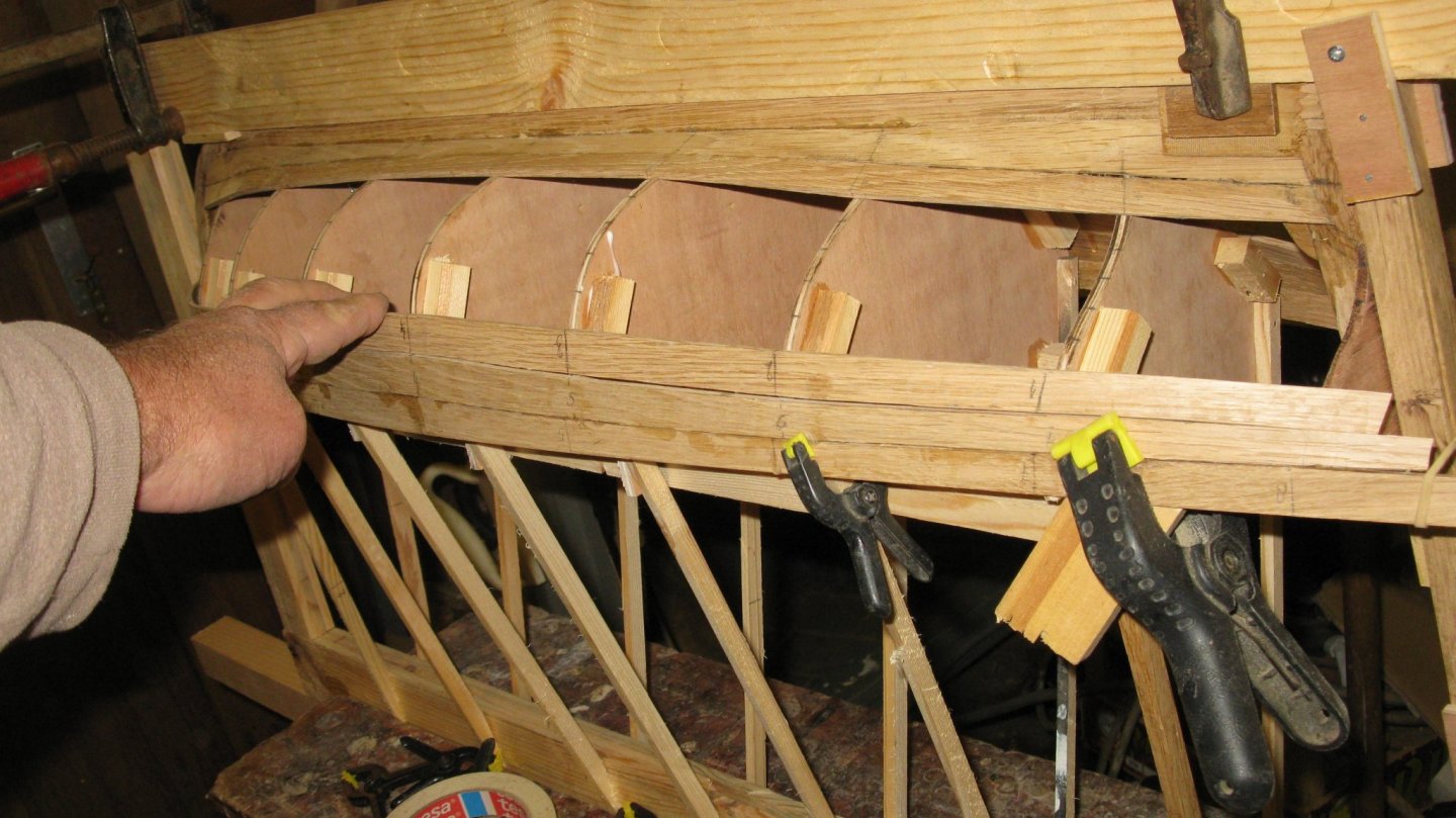
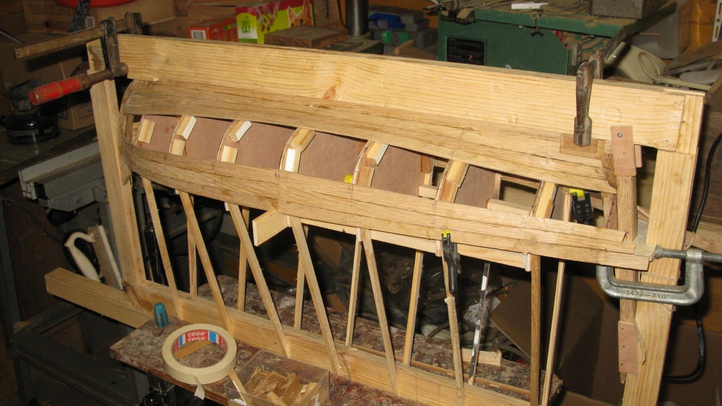
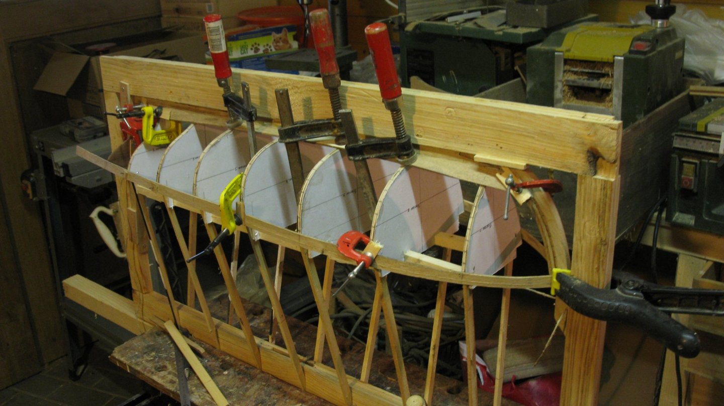
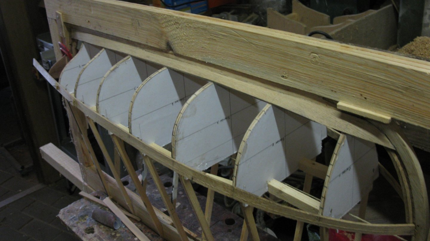
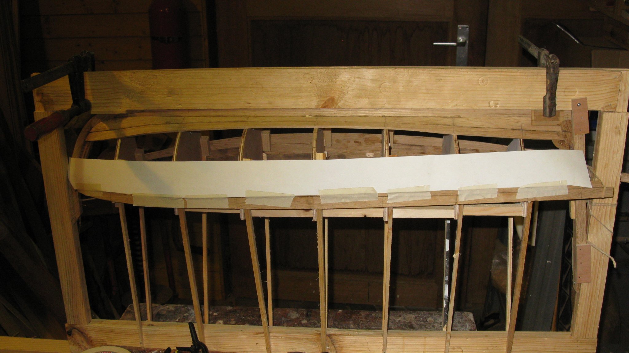
I make the 'building board' as described in practicum of Mr Van Beylen. It is a simple rectangular frame in which the model is fixed with some nails and some small wooden support blocks. A piece of string is stretched to center the stations.
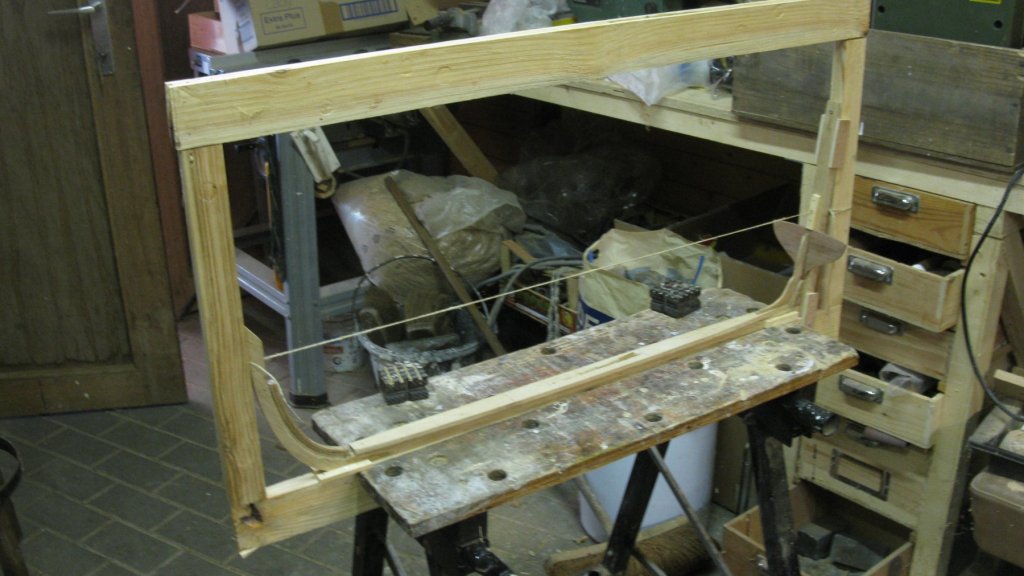
With the stations lined up and centered.
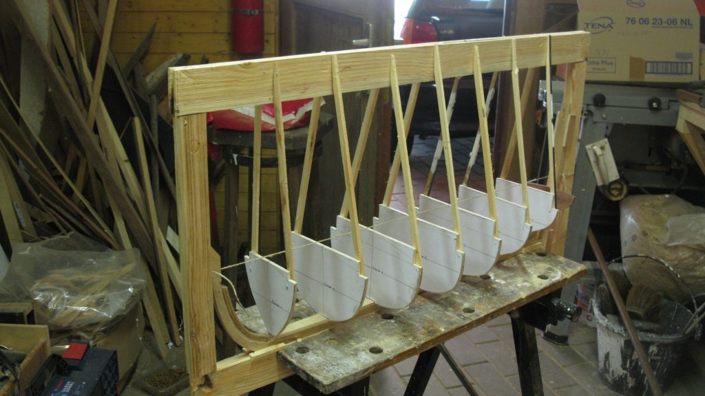
I add support blocks between the stations for strength.
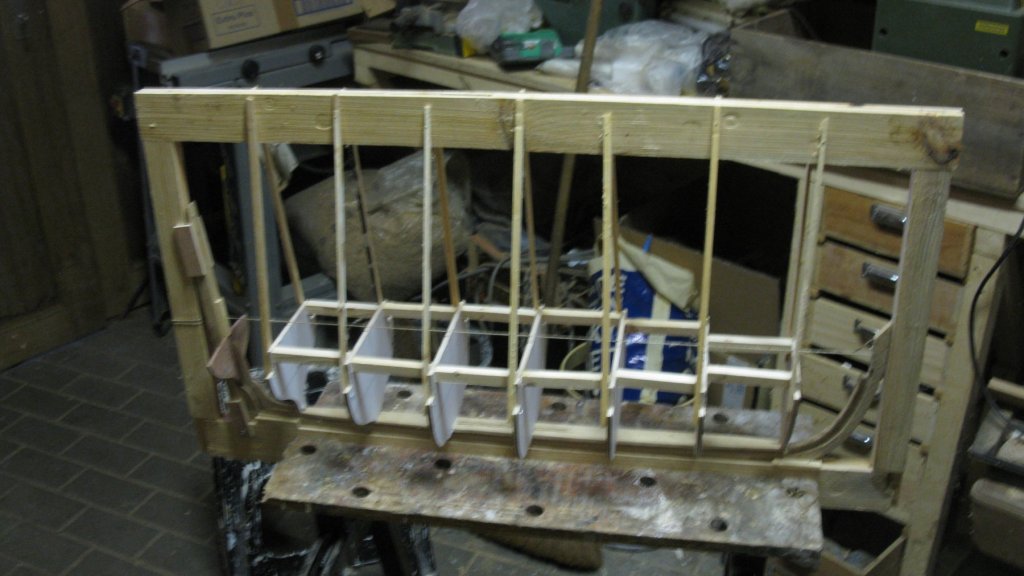
The handy thing about this kind of building frame is that you can clamp it in the workmate in all kinds of positions.

With the stations in position, the edges of the inner keel can be chamfered in accordance with the angle of the station bottom.
Thank you for the likes and till next week!
- GrandpaPhil, mtaylor, yvesvidal and 11 others
-
14
-
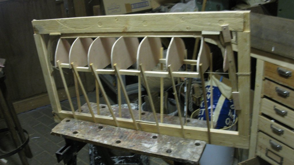
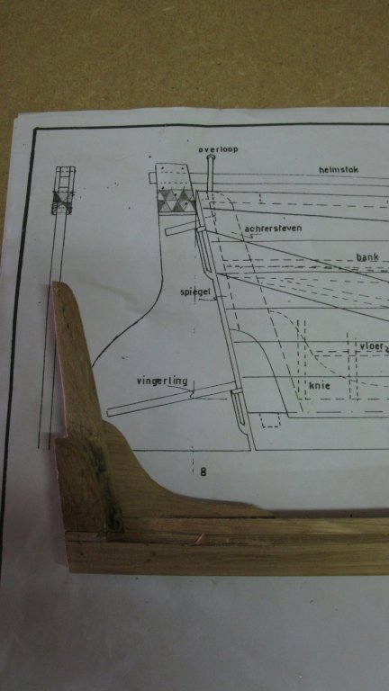
The inner stem.

Before gluing the inner stem into position, I make the notch for the planking in the stem.
I saw also the knee for the stern post.
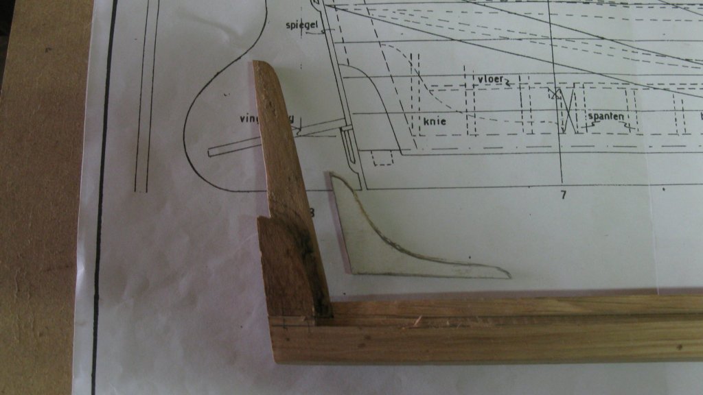
Knee into position.
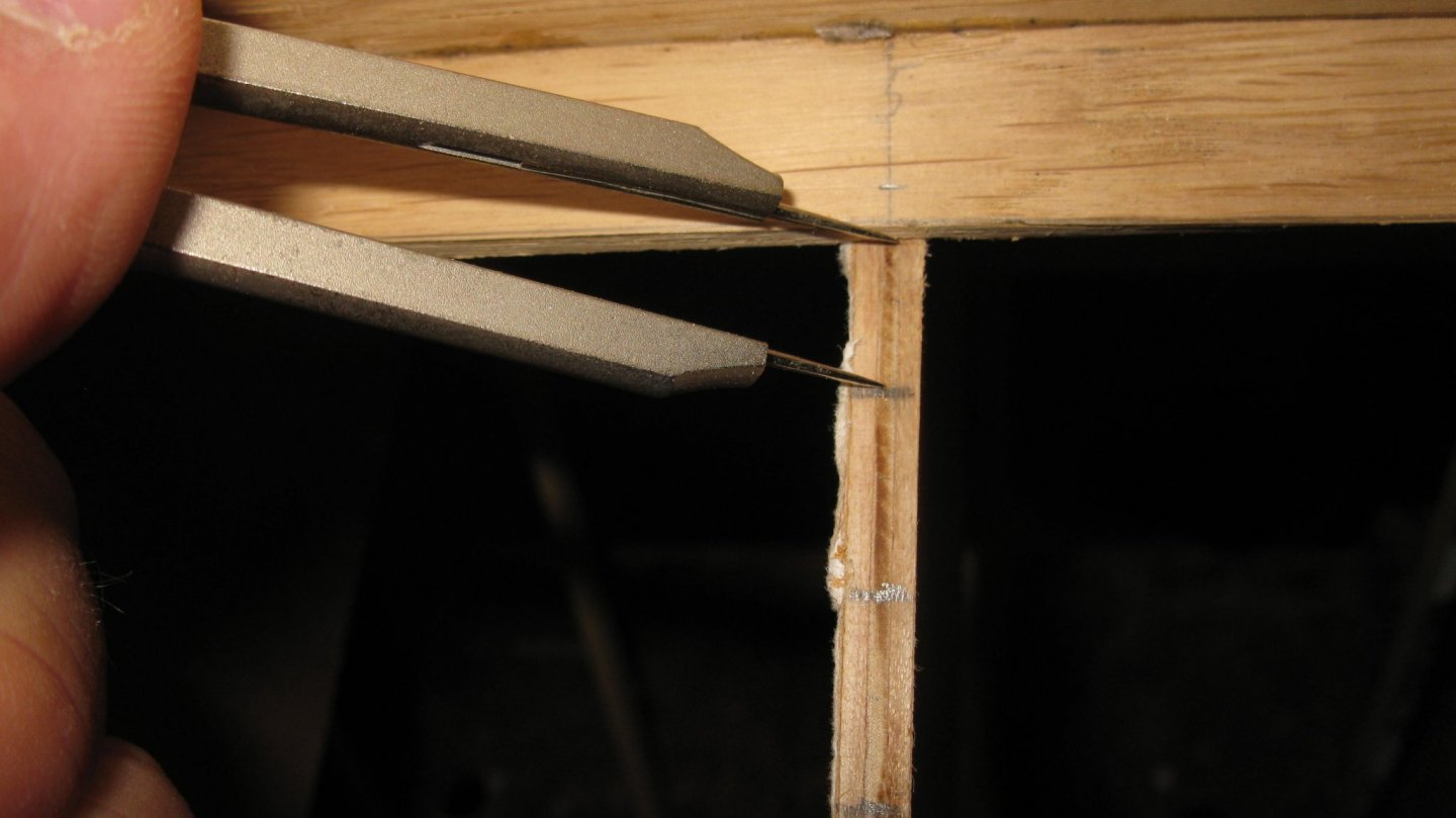
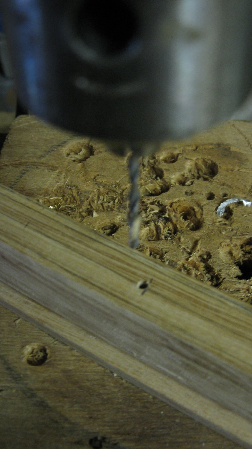
My project is a boat with a centerboard, so there has to be a slot in the keel to house the centerboard. To make the slot I start with drilling some 2 mm ᴓ holes right next to each other to be able to jig saw the slot.

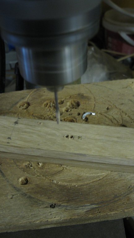

The slot is sawn, It still has to be cleaned up with a flat file and sandpaper.
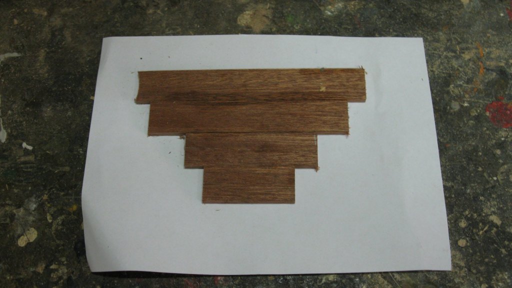
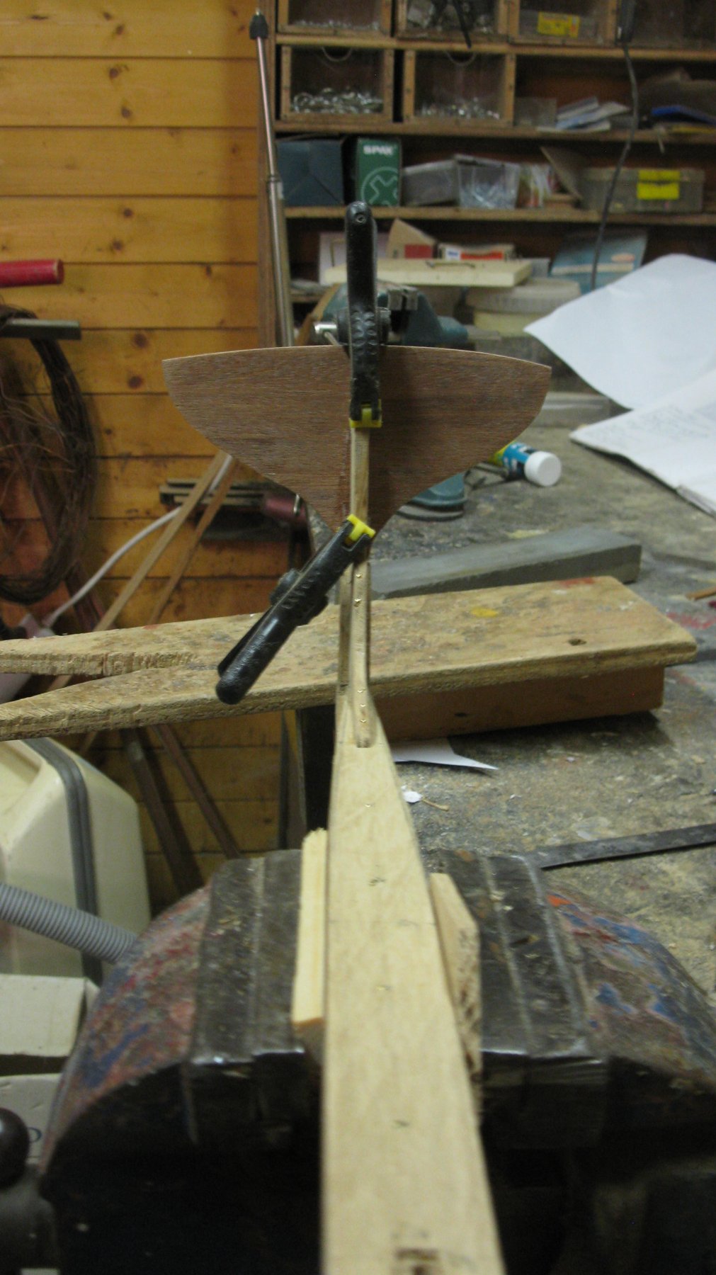
Preparing the stern of the boat. Some 4 mm thick mahogany planks glued together on the stern template.
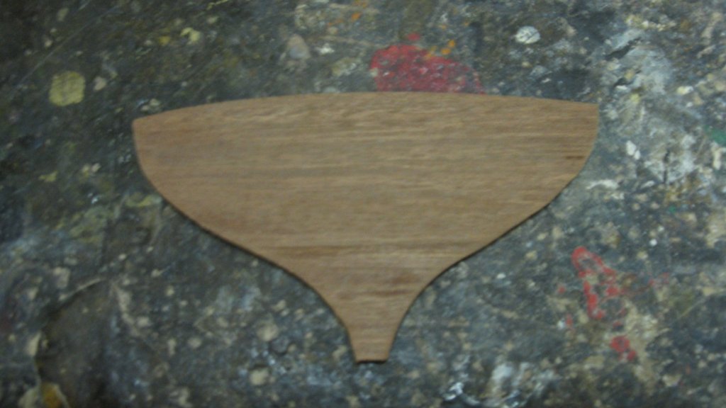
The stern sawn out.
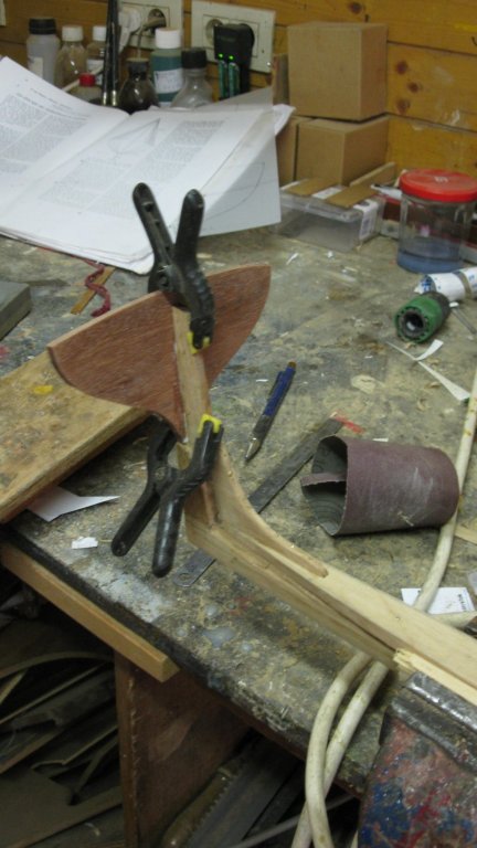
Gluing the stern into position.

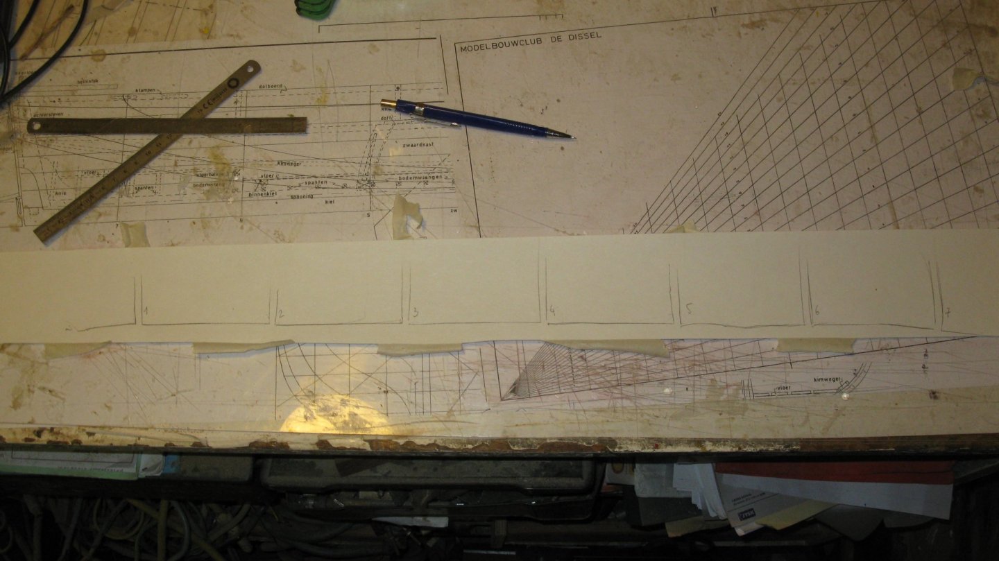
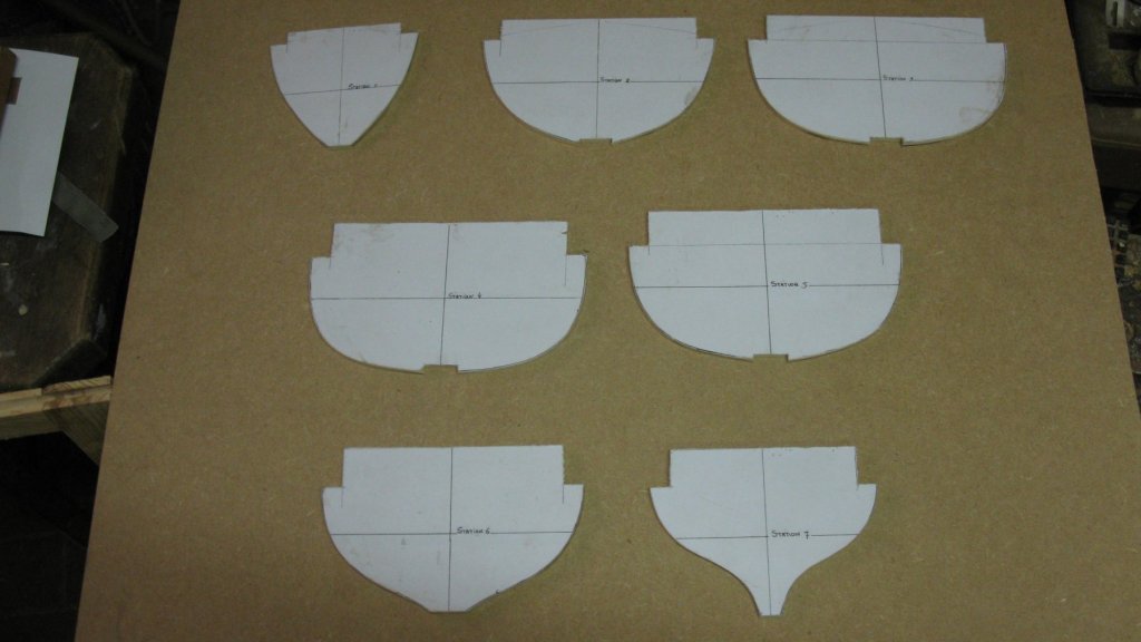
I made paper templates of the seven remaining stations and glue them on a piece of plywood.
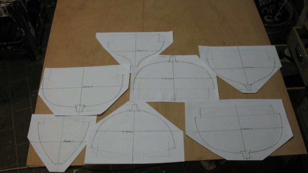
and saw them out.
Thank you for the likes and till next week!
- Mirabell61, wefalck, FriedClams and 6 others
-
9
-
Very nice work, Nils. The engine turned out very good.
The two men crew gives a real live touch to the model.
-
-
-
And all of that without one drop of blood...
- mtaylor and giampieroricci
-
2


Daysailer by G.L. - FINISHED - scale 1/10 - SMALL - gaff-rigged sailboat with centerboard
in - Build logs for subjects built 1901 - Present Day
Posted
You are right Druxey. Anyway I managed to plank the gaff sailboat in a more ar less proper way, but it can be done better. I will look for a next project in which I can exercise planking in a 1/10 scale using the information of the articles. It must be a simple vessel like a rowing boat, just to improve my modeling (planking) skills.
Thank you for your remark!