


G.L.
-
Posts
1,553 -
Joined
-
Last visited
Content Type
Profiles
Forums
Gallery
Events
Posts posted by G.L.
-
-
Nils,
Your engine turned out very well.
- popeye the sailor, mmdd, mtaylor and 2 others
-
 5
5
-
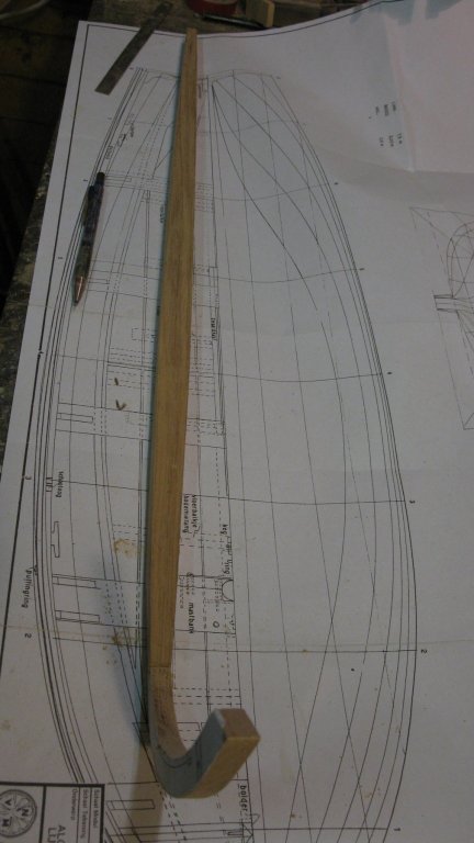
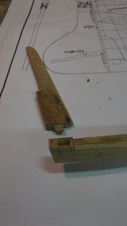
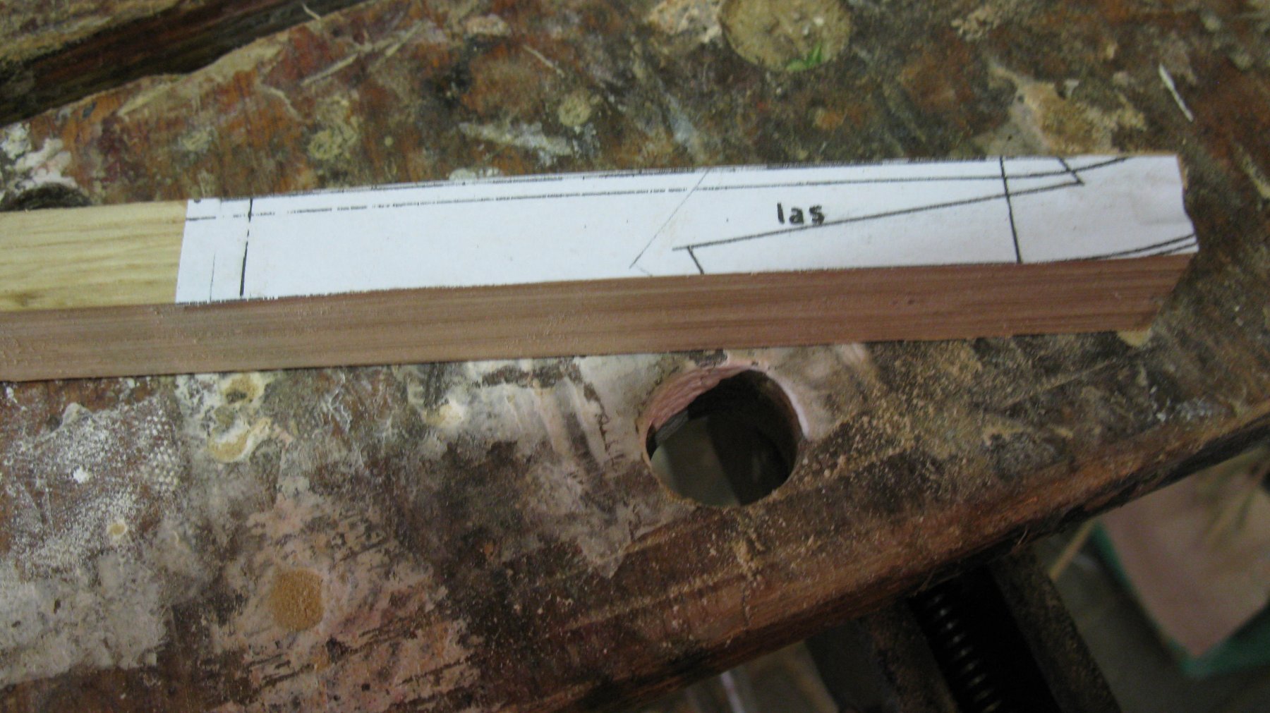
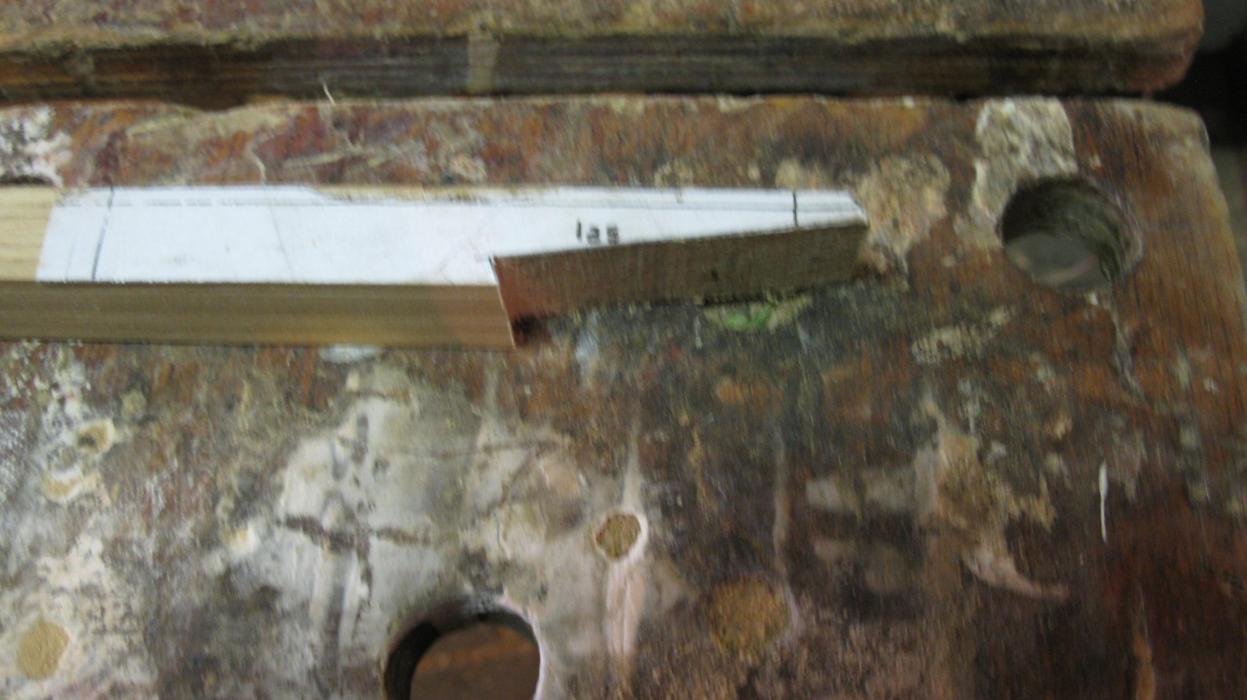
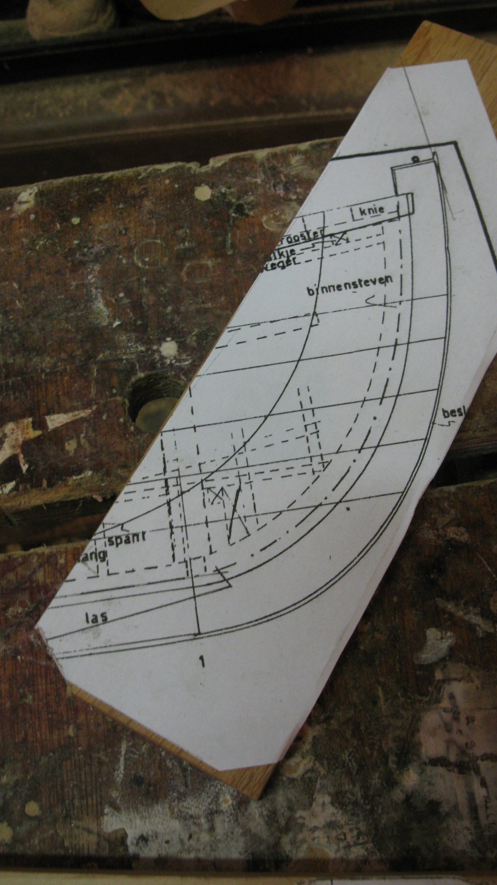
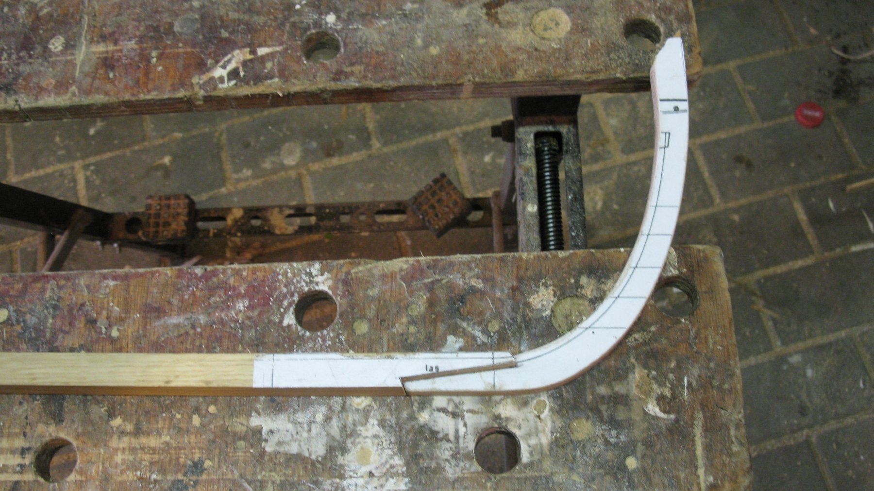
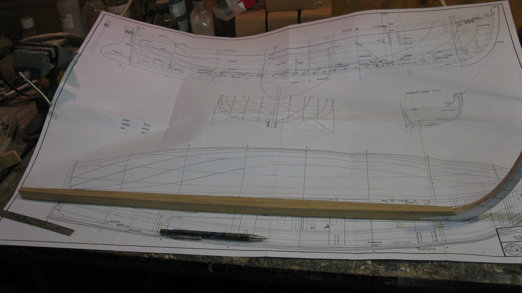
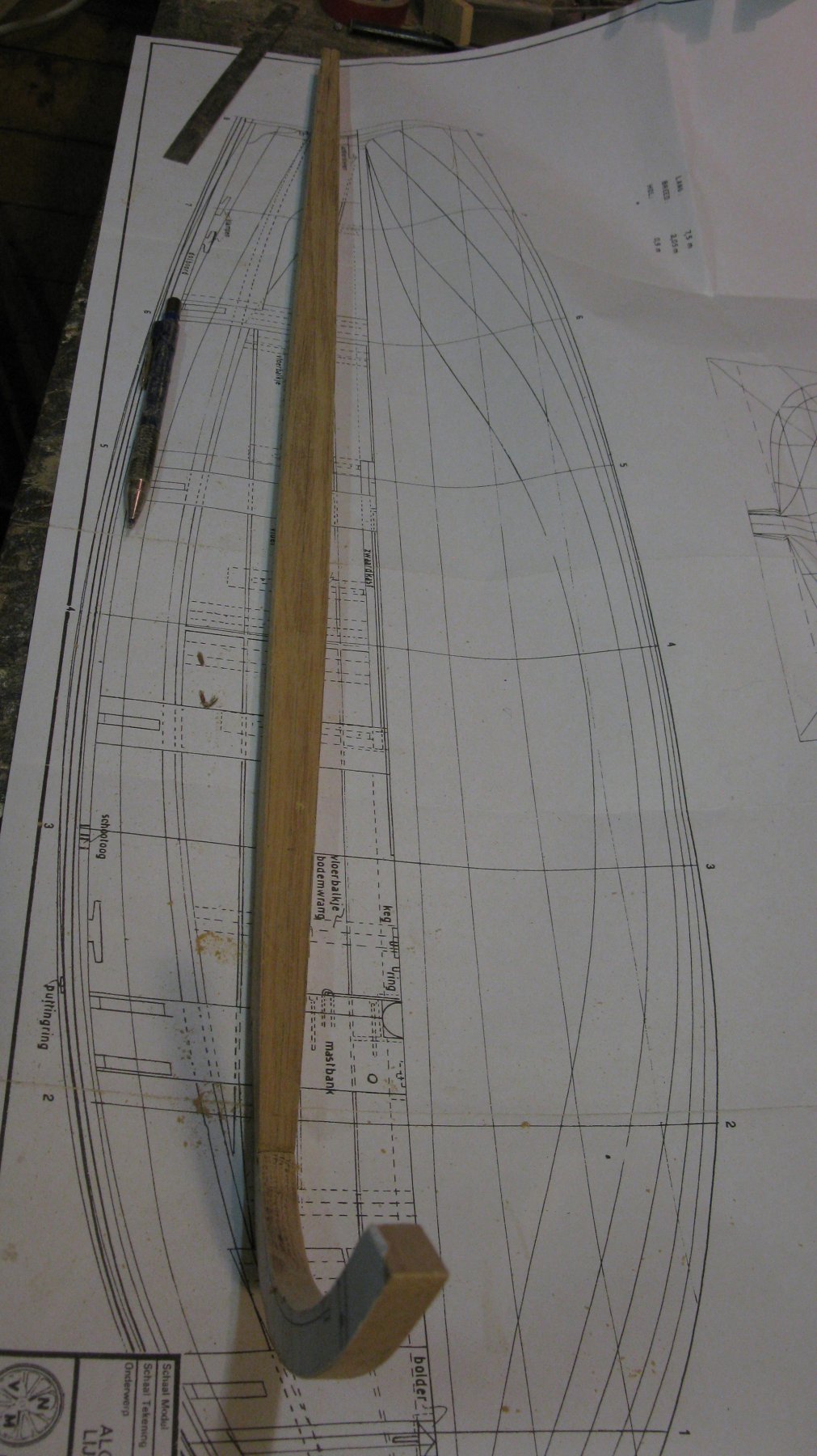
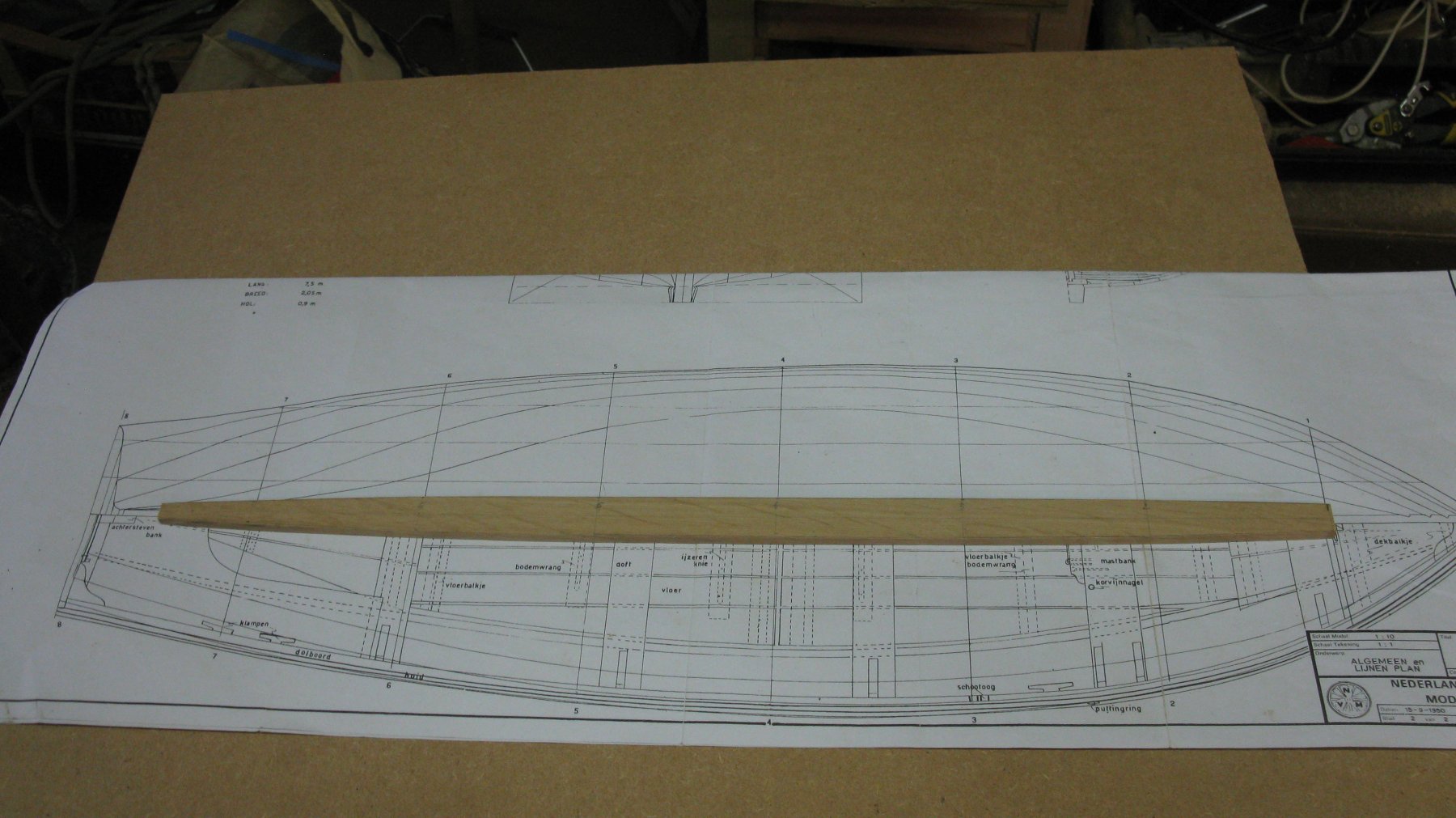
Part 2: Keel, stem and sternpost
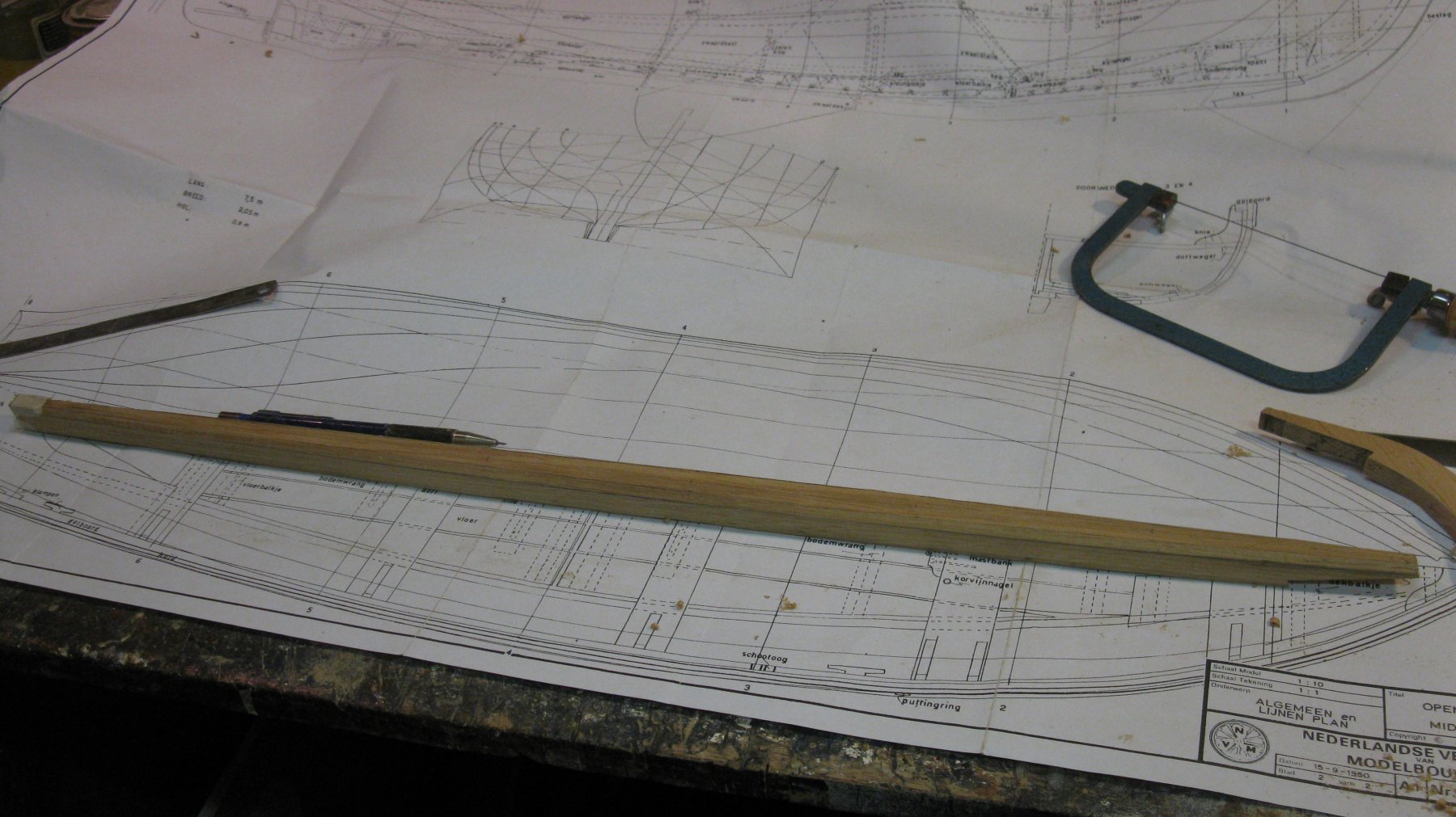
I start with making the keel out of a 65 cm long piece of oak.
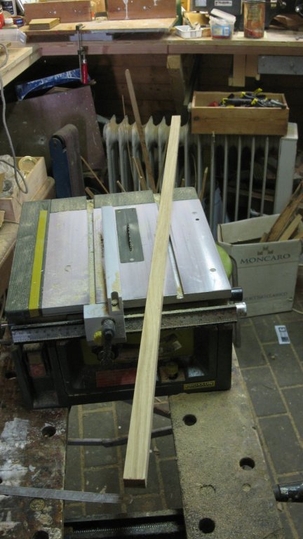
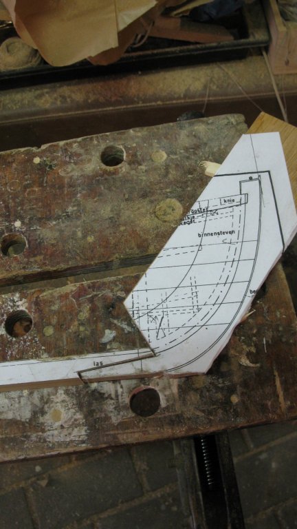
At the front I saw the joint for the stem.
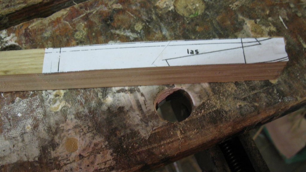

The stem, also in oak is sawn out and the joint is checked with the keel. I leave the upper side of the stem a bit longer than needed. It will be sawn in model later.


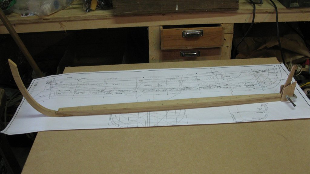
The width of the keel is not the same everywhere. The keel is widest in the middle and becomes narrower towards the ends. I shape it with plane and band sander.
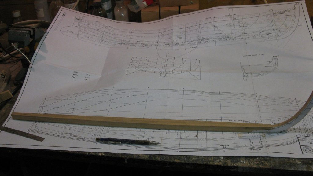
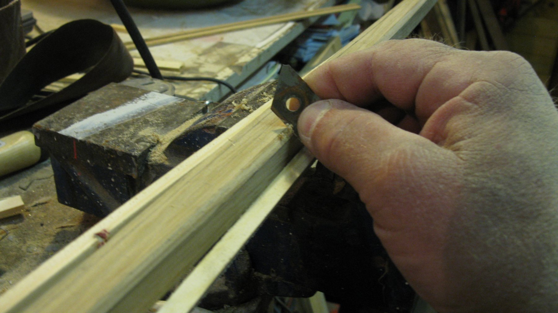
I scrape off the angles of the upper side of the keel to make the notches for the garboard strake.

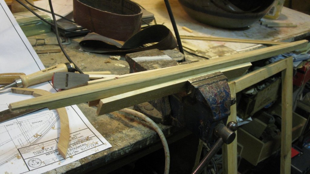
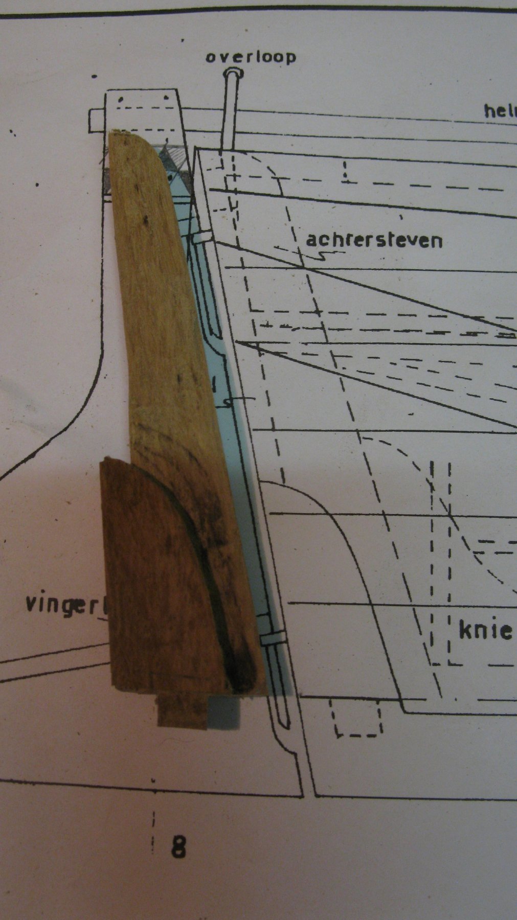
A major part of the stern post is sunken. I use a fixed-base router to shape the stern post.
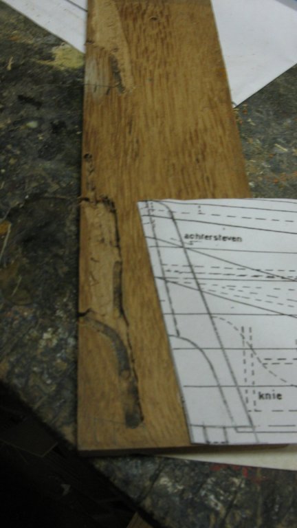
Then I saw it out with the fretsaw.

The connection between sternpost and keel is strengthened with a pin at the sternpost and a hole in the keel.
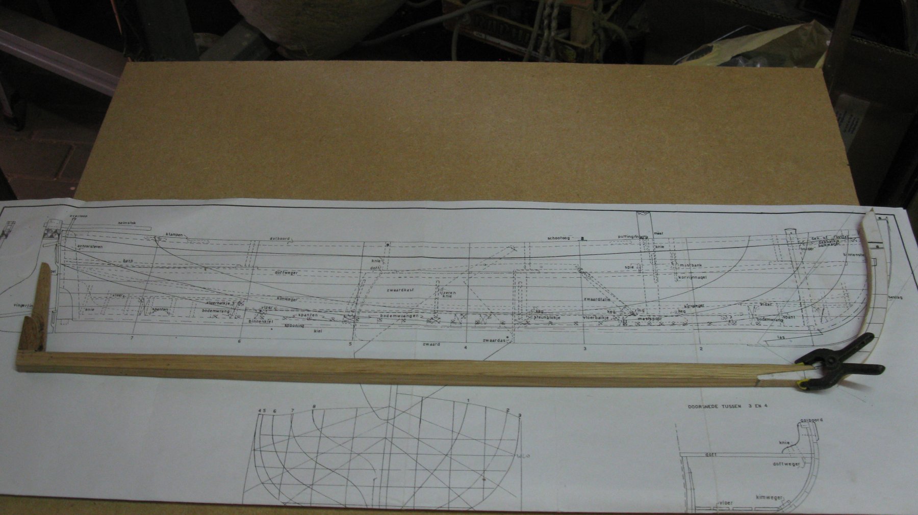
Checking if everything fits.
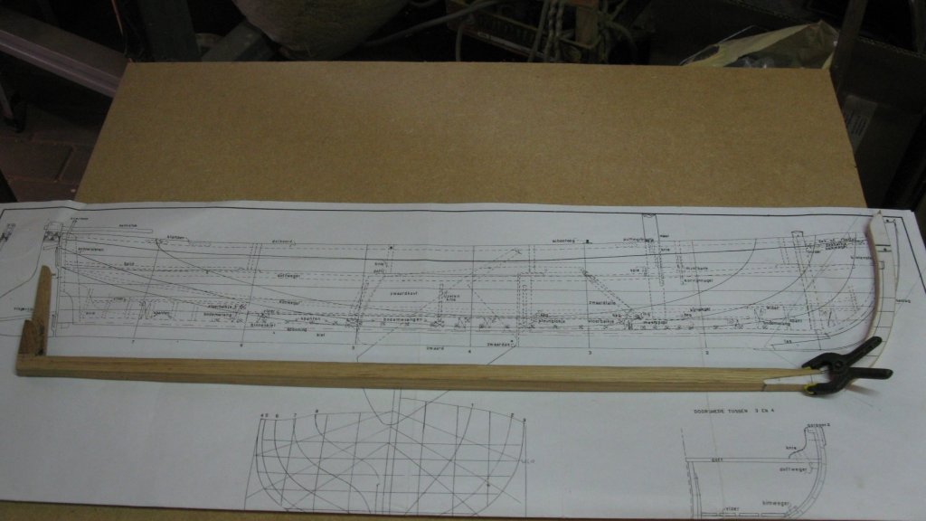
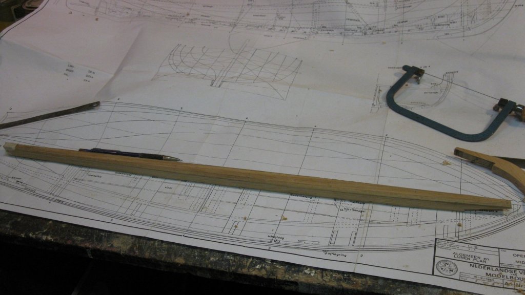
The inner keel is a four mm thick plank which narrows towards the ends. The different widths along the keel are measured at the bottom of the eight stations.

Time to glue and nail everything together.
Thank you for the likes and till next week!
- vaddoc, mtaylor, Mirabell61 and 7 others
-
10
-
-
-
That are really nice pictures.
- popeye the sailor, mtaylor and Canute
-
3
-
-
Part 1: Introduction
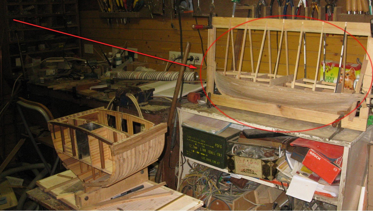
My fishing smack cross section is finished; a new project is already sprouting. But first my workshop is urgently in need of a deep cleaning and there are also a lot of jobs waiting for me in and around the house of which the priority must be upgraded if I want to preserve the peace in the household. So the start of my new project will have to wait.
That does not mean that I will go off-line for a while. While making the fishing smack cross section, I was simultaneously working at another POF model.

I didn't want to keep up two logs at the same time, but now the pictures are sorted and the model is well advanced, enough to keep the log running while I am busy with other things. I can continue giving weekly updates retroactively at least until I am ready again to start a new project.
My previous building projects were working boats (Ostend shrimper and fishing smack) and a warship (HMS Triton cross section). Now I want to build a pleasure boat.
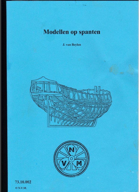
I found my boat in an small handout for making plank-on-frame models that I bought some years ago from 'Nederlandse Vereniging voor Modelbouwers' (http://www.modelbouwers.nl/ ). The handout is an assembly of articles which appeared round 1950 in the Dutch magazine 'De Modelbouwer'. They are written by Jules Van Beylen, former conservator of the Belgian National Maritime Museum in Antwerp. In the handout Jules Van Beylen explains how to build plank on frame models on the basis of four small ship models varying from basic to moderate level.

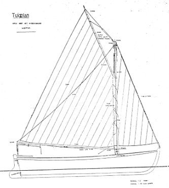
The second model of the handout will be the subject of my project. It is a small gaff sailing sloop with a retractable center board. It is an imaginary boat, a design of Jules Van Beylen just for modeling. I doubt that real examples of it ever have been built.
One of my previous builds, a coastal fishing sloop was a simple boat, but it took me almost three years to build it (and it is not yet complete now). This is a much more elementary model, so it will be finished somewhat faster. The plans include two sheet: a general construction plan and a rigging plan and are not included in the handout, they have to be bought separately at the 'Nederlandse Vereniging voor Modelbouwers' (http://www.modelbouwers.nl/). They are laying already some years in a drawer waiting to be used.The model will be built at scale 1/10. It is a 7.50 m long hull, so the length of the model will be 75 cm.
- GrandpaPhil, KORTES, FriedClams and 7 others
-
10
-
-
Will you place such a railing device also?
- yvesvidal, Canute, thibaultron and 2 others
-
5
-
Nice done, the opening in the deck to show the ballast stones.
The boxes for the catch, were they filled with water to preserve the fish alive?
-
-
Nice work, Jim.
Will you plank the whole hull or will you leave a part of the frames uncovered?
-
The skipper seems to be happy with his new berth 😃.
- Mirabell61, cog, mtaylor and 4 others
-
7
-
-
-
I made some detail pictures of the cross section. They can be watched in the gallery.
- mtaylor and Mirabell61
-
2
-
On 7/21/2019 at 10:54 AM, cog said:
Very well done. I really do like your display. In all a build which was fun, creative, and educational. Thanks for sharing
22 hours ago, Sea Hoss said:Fantastic work!
18 hours ago, FriedClams said:Congratulations on the completion of your beautiful model G.L Your methods and approach to modeling are ingenious, effective and the results drip with authenticity. I enjoyed your log and will miss the updates. Thank you for sharing this with us.
Gary
7 hours ago, mtaylor said:Well done, G.L. The drydock really adds something to the appearance.
Thank you Carl, Sea Hoss, Gary and Mark, It was also great fun to me to build the model. I am very glad that you liked my log. I hope that I can interest you with new projects in the future.
-
On 7/20/2019 at 1:31 PM, Backer said:
Great work on the dry dock (and the cross section of course).
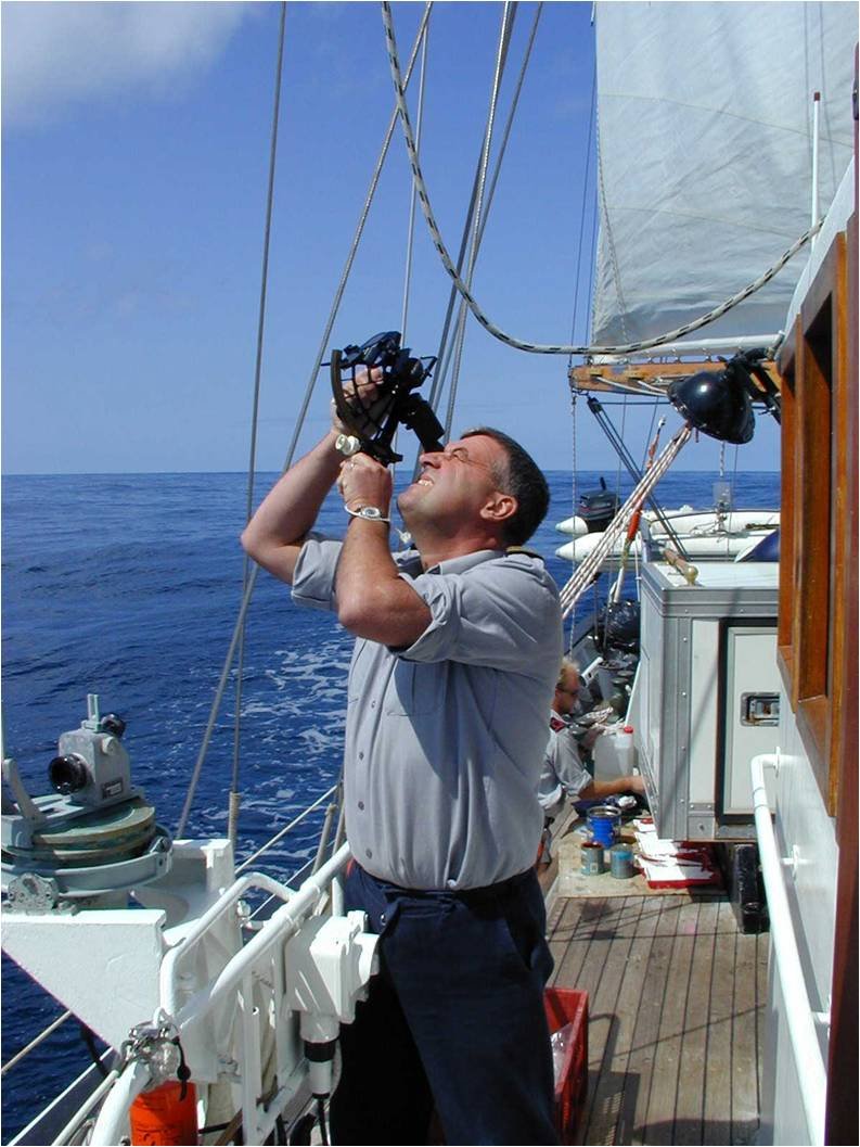
The navy sail training ship, was this the Zenobe gramme??
Yes Patrick, it was BNS Zénobe Gramme (A958).
I had command of the ship during 4 years, the most exiting years of my career.

- Baker, FriedClams, mtaylor and 1 other
-
4
-
-
-
Nils, you are going full ahead. Nice work.
-
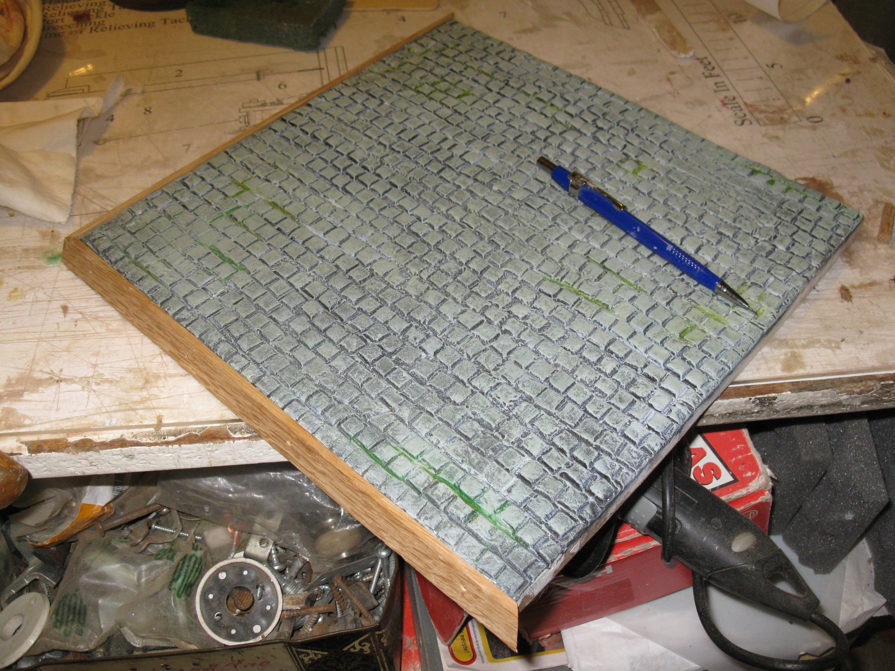
24. The display board
I guess this will be the last part of my building log.
Here you see an almost two decade old picture from the time I was captain of the navy sail training ship. The picture is made in the navy yard in Zeebrugge during the winter maintenance of the ship. This picture gives a good idea of what I have in mind with the display board. I want to present my cross section on blocks like it would be laying in a dry dock.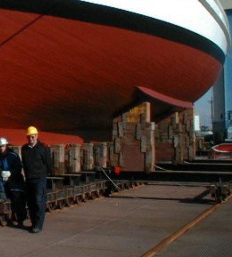
I suppose that the floor of a dry dock in the twenties was a not a nice flat surface in concrete as it is in the navy dock yard, so I will cover my floor with cobblestones.
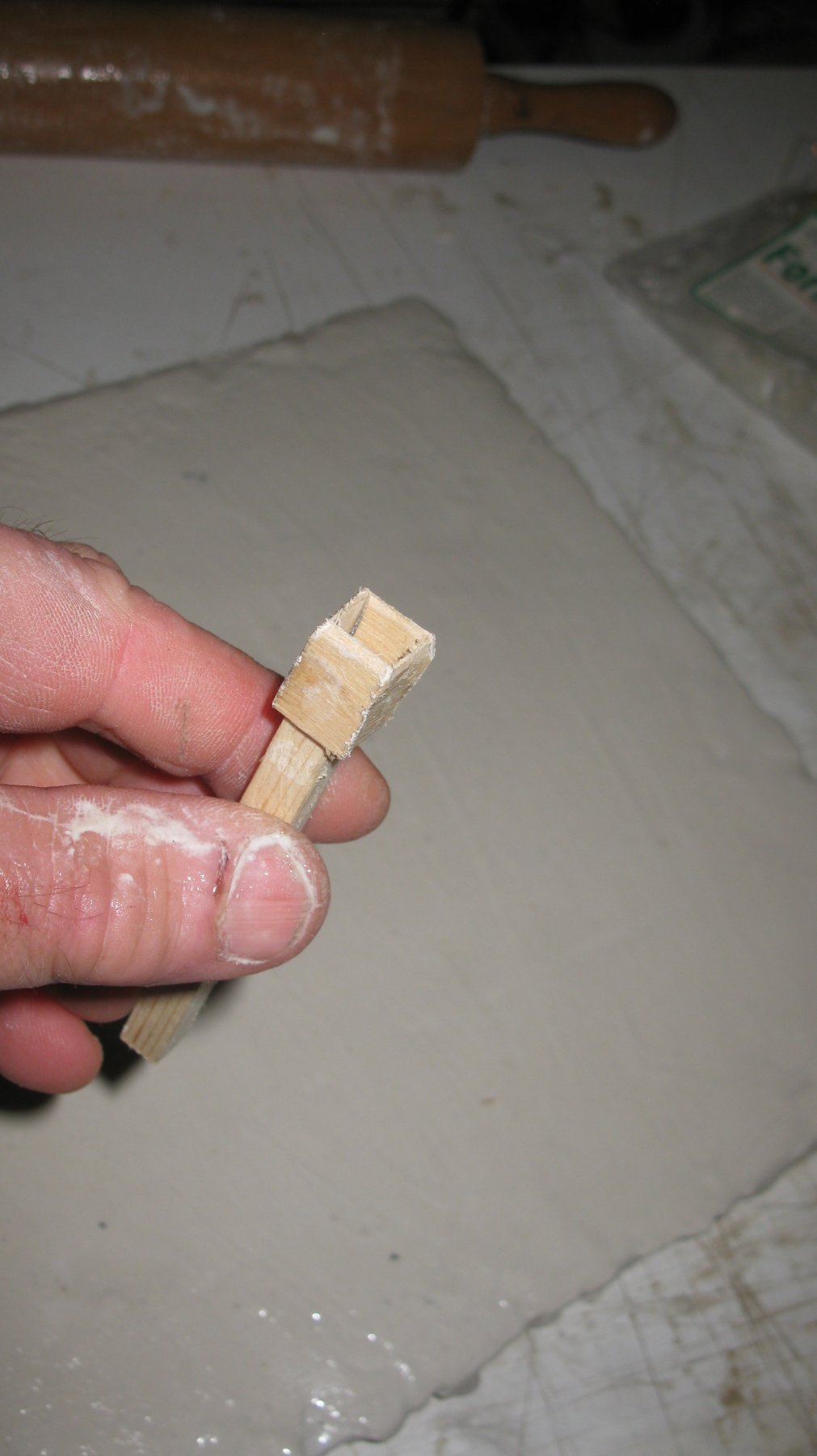
I start with sawing a board of 12 mm MDF plate.
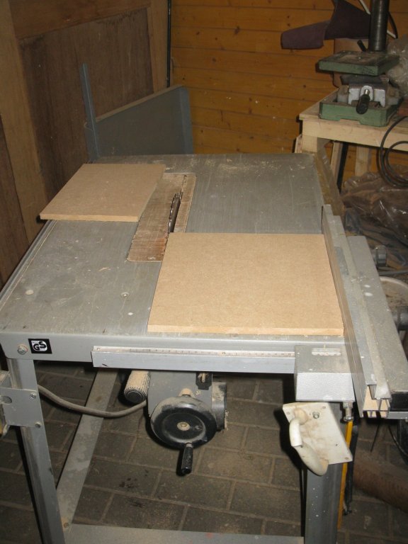
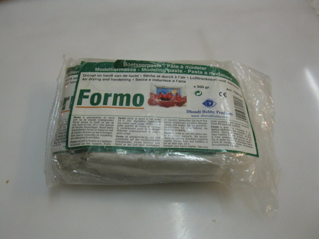
Then I coat it with white wood glue and on top of it I roll out modeling paste to a thin layer of two to three to mm thick with a rolling pin. I wipe the surface smooth with a wet sponge.
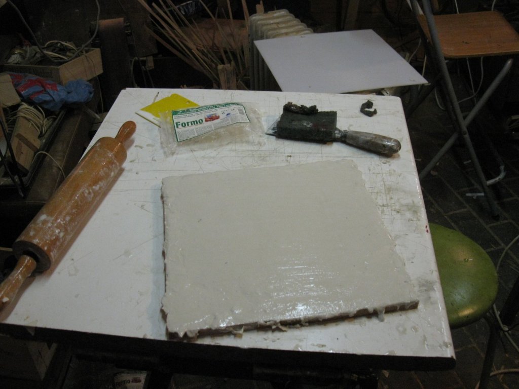
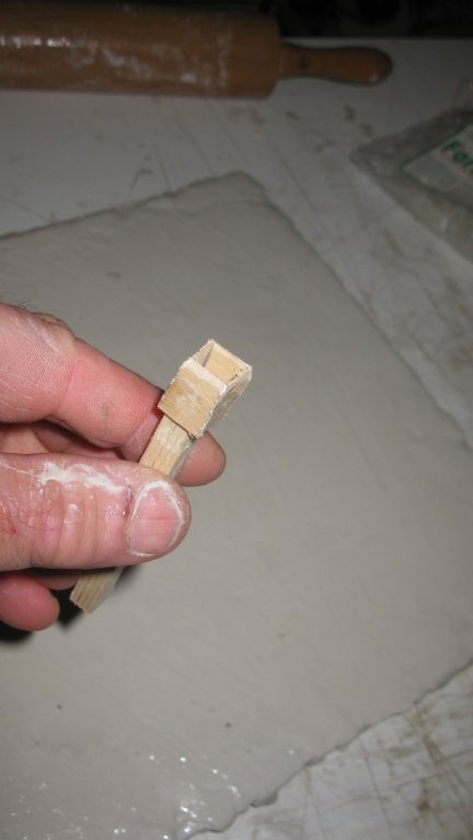
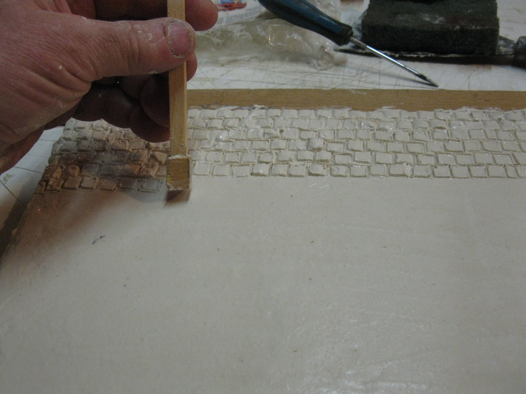
I made a wooden punch with the sizes of the cobblestones (± scale 1/20) and start stamping until the whole surface is covered with small squares. I try as much as possible to interchange the grouts between the stones in each row.

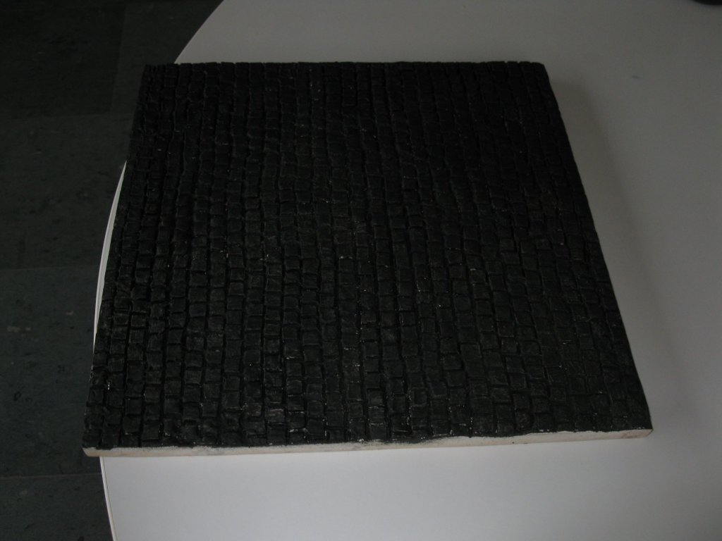
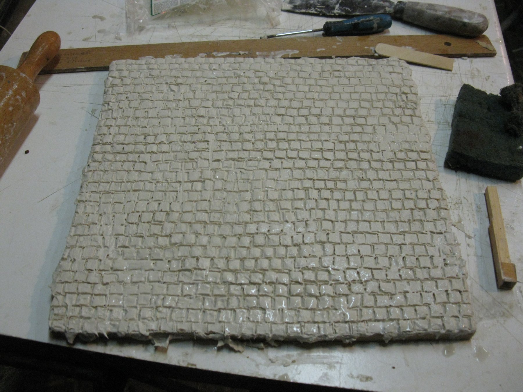
When the whole board is done. The paste may dry and some days later lightly sanded to get rid of sharp ridges.

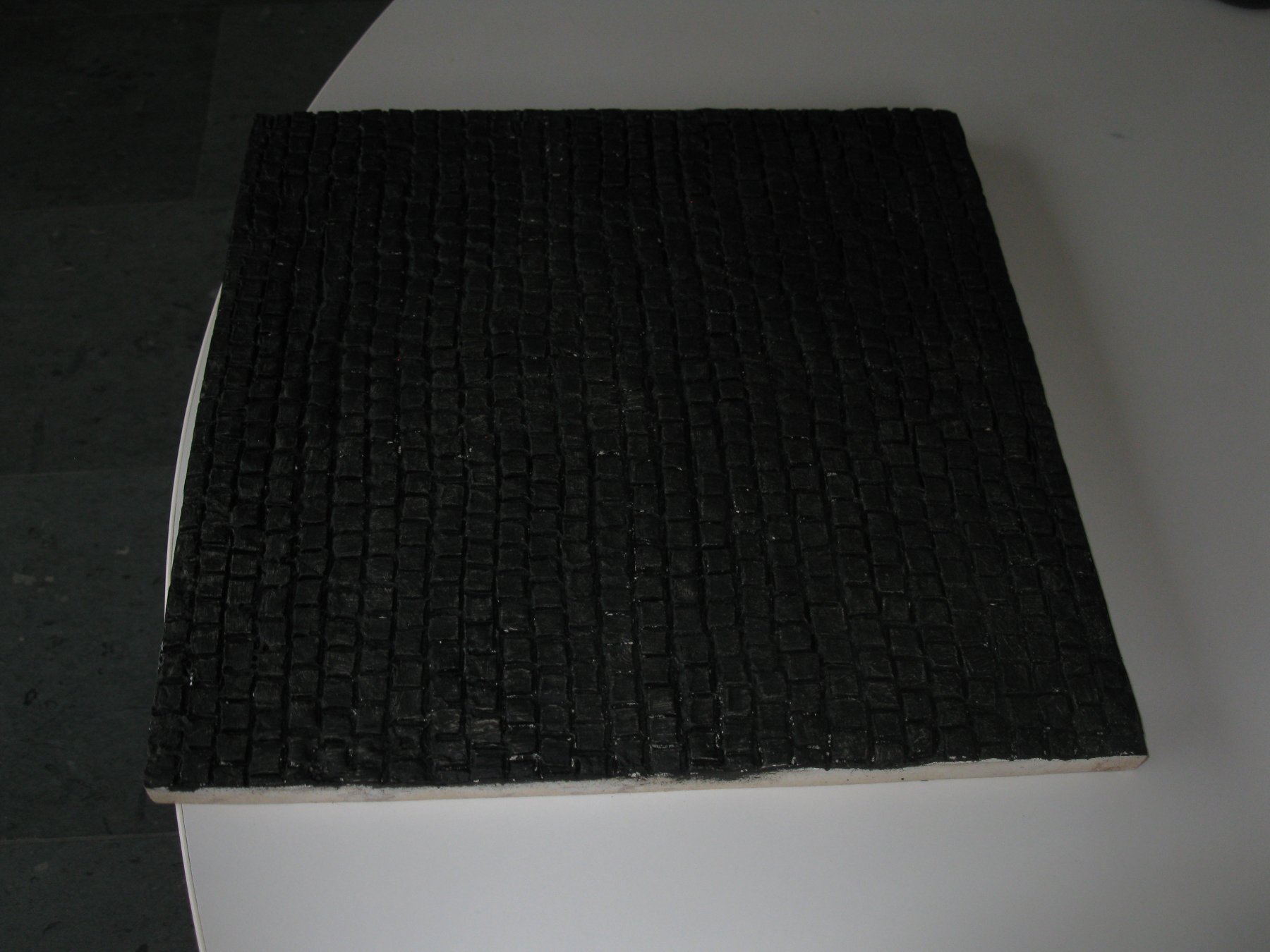
Then I paint the whole surface with black acrylic paint. I make sure that all groves between the stones are covered with paint.
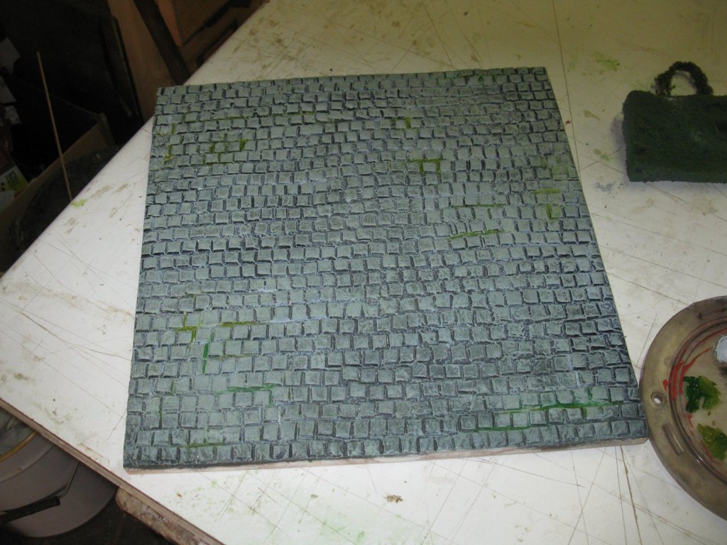
When the black paint is dry I dry brush it with gray paint to simulate the granite color of the stones and then here and there with some green hues for some moss and weeds between the stones.
Finally, I give the board an oak frame and varnish the whole board with mate varnish.

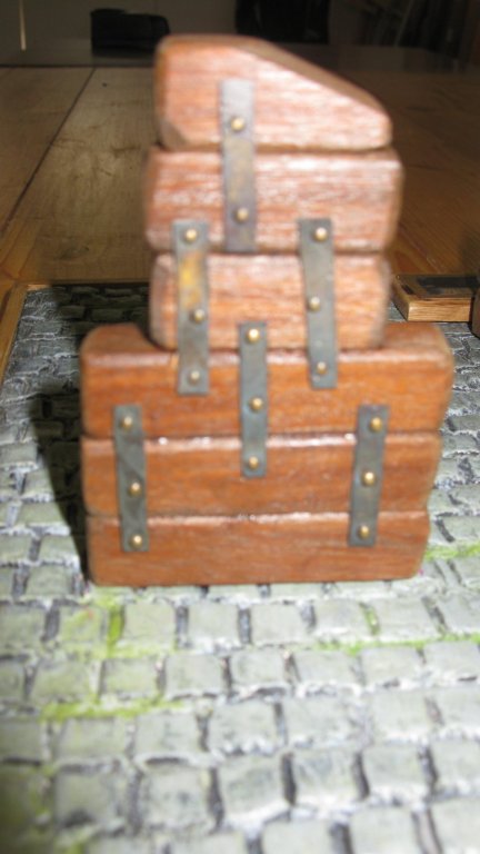
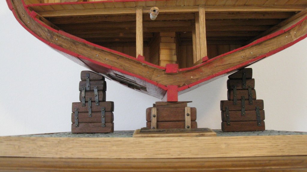
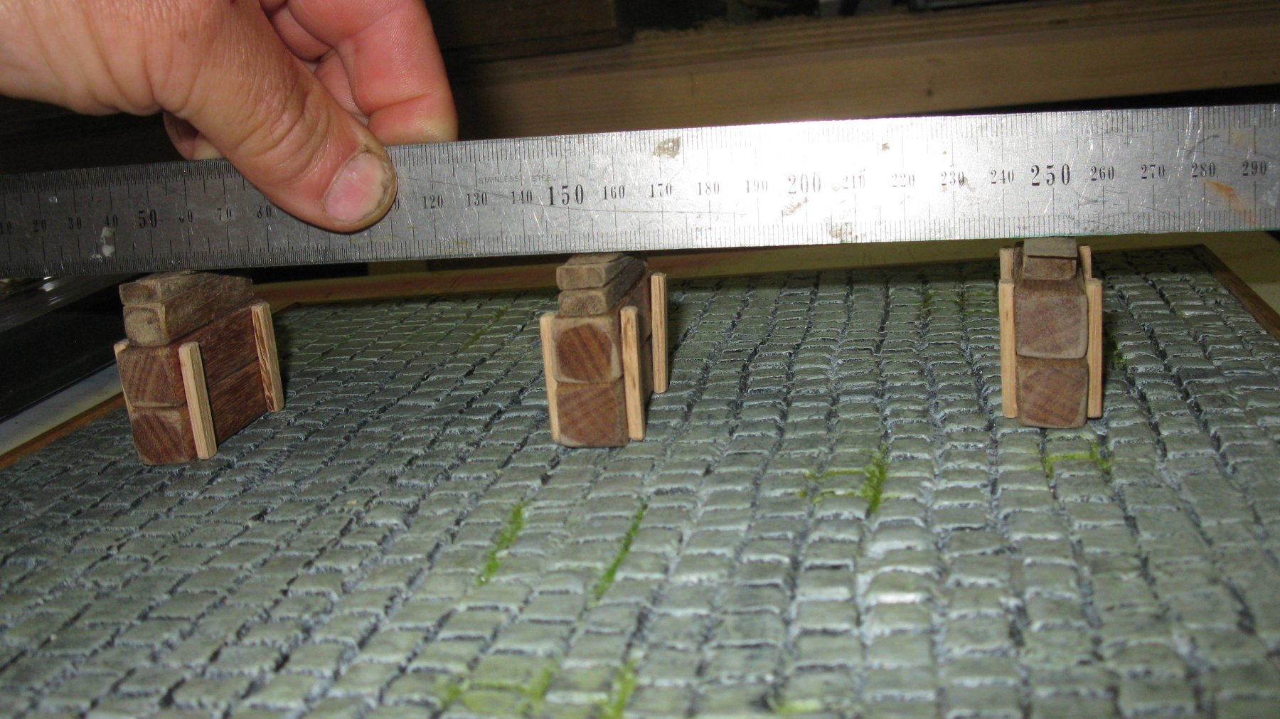
Now I make the blocks. The keel of the cross section will stand on three piles of blocks. Gluing the piles:
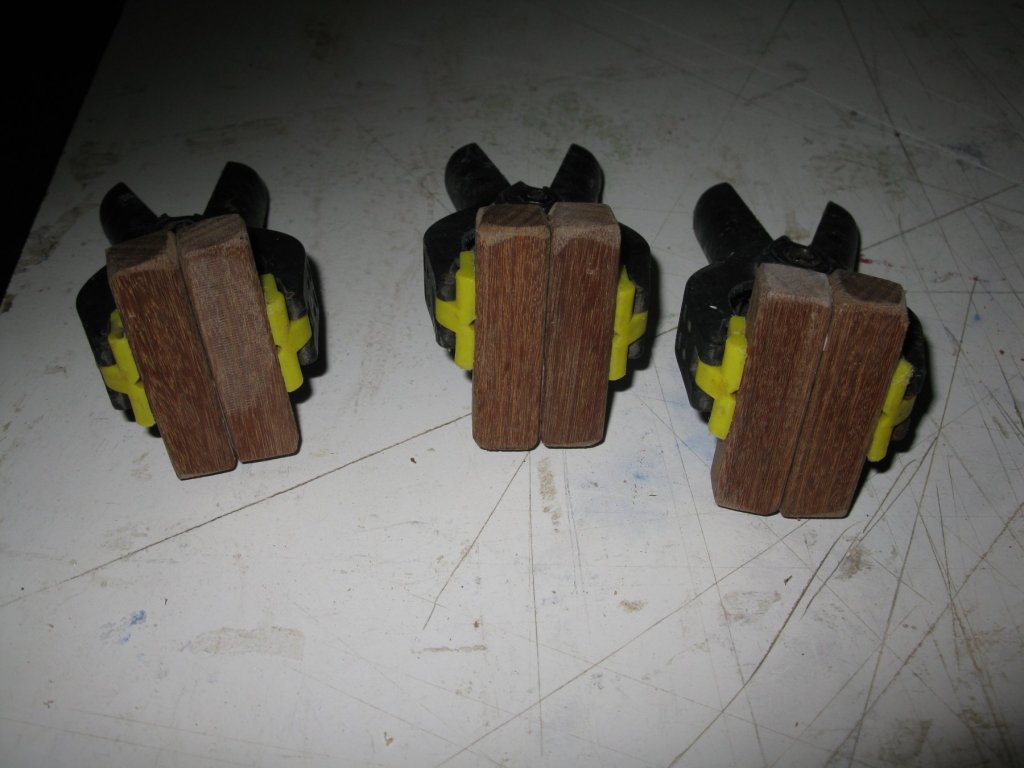
Lining up the piles on the display board and making the spacers.

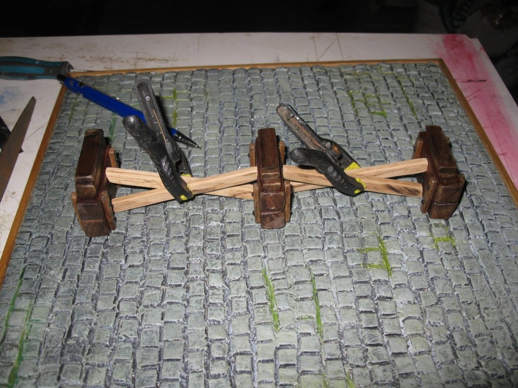
Determine the positions of the side piles. I use a spirit level to check if the model is standing horizontally.

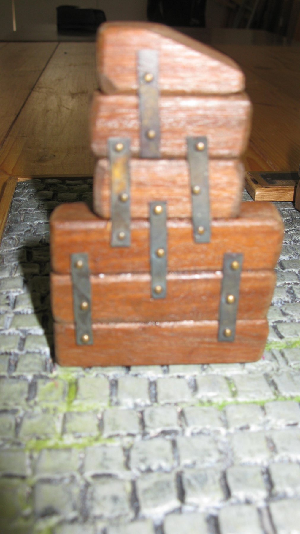
Gluing the side staples.
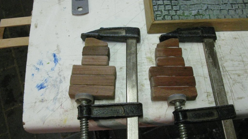
Finishing the side staples. They are bolted together with small brass plates and brass nails which are blackened. The wood of all bocks is stained with pepper color wood stain and mate varnished.
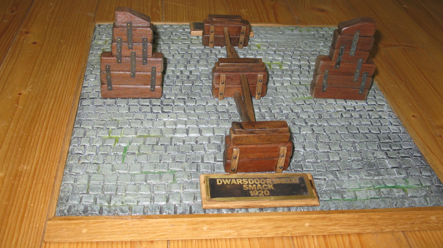
The display board, completed with name plates.

and the model standing on its seat.
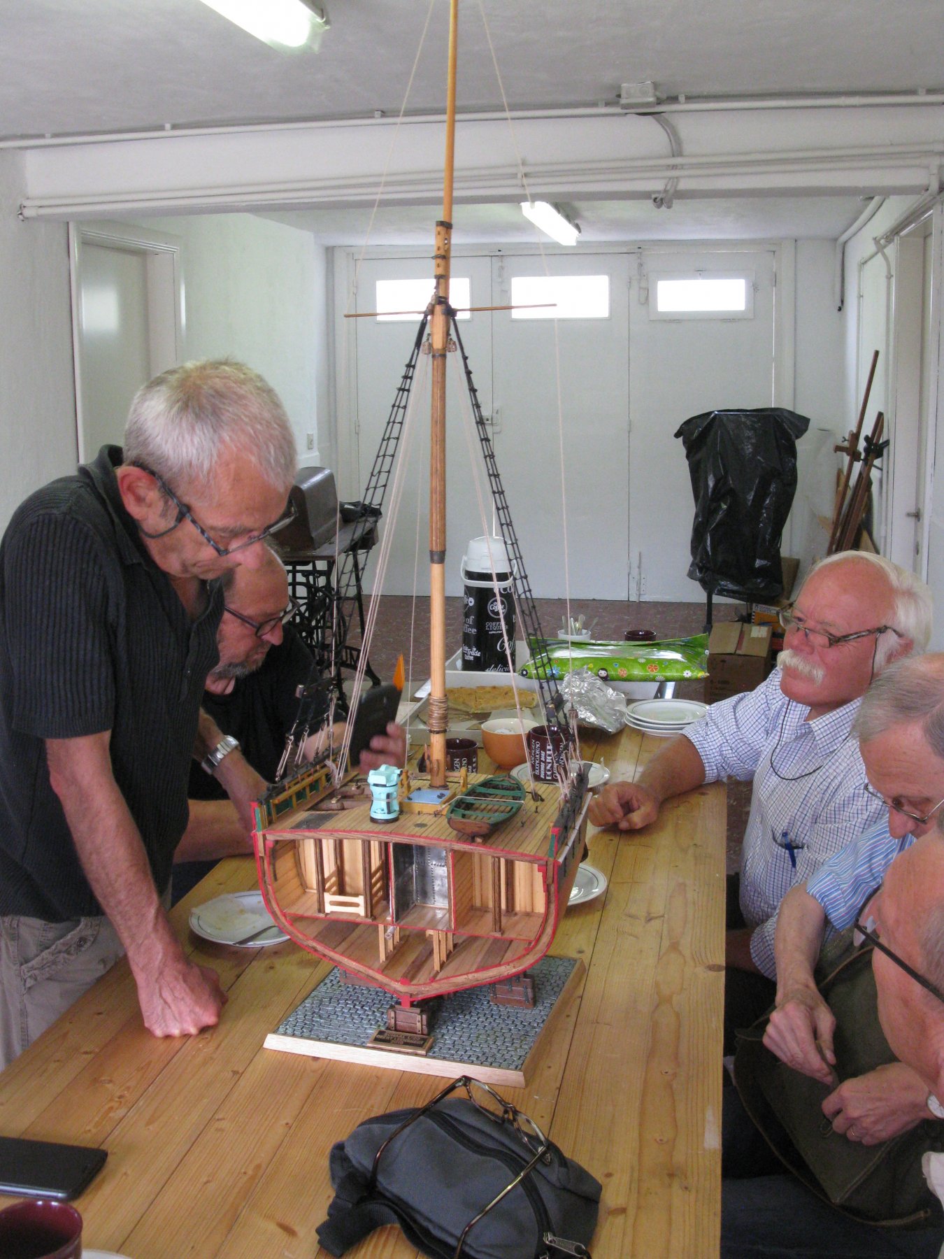
My local modeling friends were the first to see and to judge the completed cross section of the fishing smack during our monthly meeting.

During next days I will make some detail pictures of the cross section and load them in the gallery section.
- GrandpaPhil, Tigersteve, cog and 12 others
-
15
-
-


U-552 by yvesvidal - FINISHED - Trumpeter - 1/48 - PLASTIC - Type VIIC U-boat
in - Kit build logs for subjects built from 1901 - Present Day
Posted
Very realistic. Congratulations!