Chuck
-
Posts
9,726 -
Joined
-
Last visited
Content Type
Profiles
Forums
Gallery
Events
Everything posted by Chuck
-
 Thats funny and thank you. But like everyone else, I am always just learning more with every project. I do however pride myself in doing as much research as I possibly can. It usually only leads to me second guessing myself. But than you for the kind words. Chuck
- 1,051 replies
-
- 6
-

-
- cheerful
- Syren Ship Model Company
- (and 1 more)
-
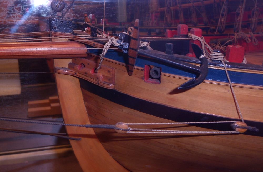
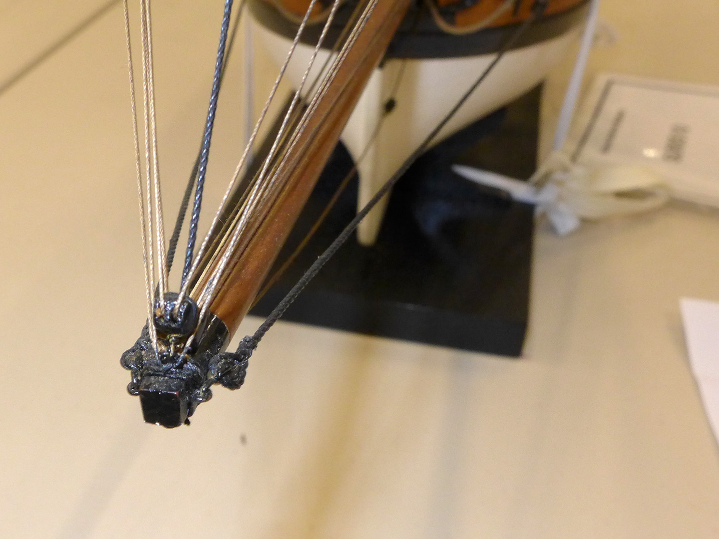
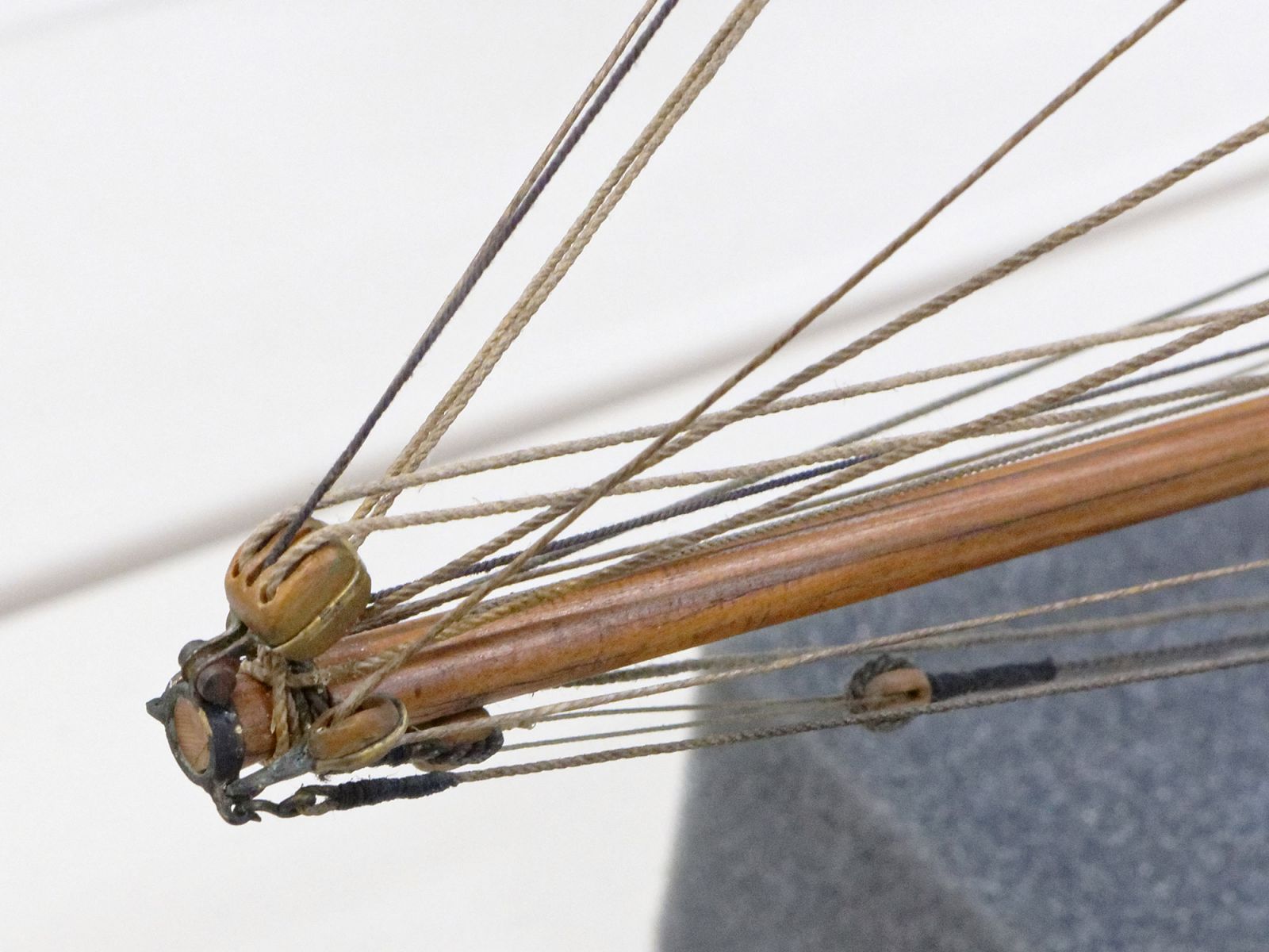
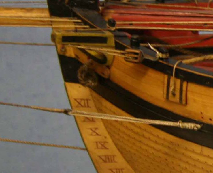
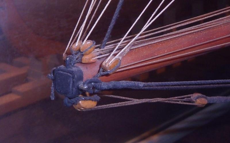
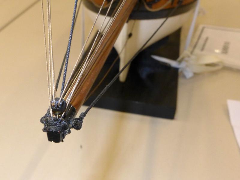
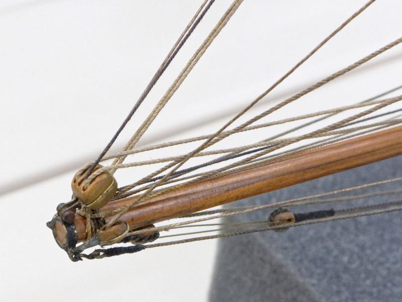
Mark , your guess is as good as mine. I actually think most ships were like this..... but because of Steele and a few other rigging texts that focus mainly on frigates, people have found comfort in being able to say its correct. But just because one or two contemporary texts write about particular methods however, it sometimes still doesnt match what you see on contemporary models with original rigging or even many contemporary drawings or other not as well known texts. You see so many contradictions. I believe its fair to say that you can use what you find in a contemporary rigging source but you shouldnt get so comfortable or insistent that its the correct and only way it was done. For each time you read or find another so called contemporary example....you will ultimately find two more that are completely different but just as plausible. I think when it comes to rigging there was a lot of experimentation and different methods that were acceptable. As an example.....the bobstay on a cutter after 1800. I have seen them with tackles set up with blocks. I have seen them with deadeyes and a lanyard. I have seen some with no bobstay at all. With regard to the bowsprit guys....the same is true. Some have a lanyard between thimbles and an eyebolt as I show it. Others have it set up with blocks and a tackle while others also use deadeyes. Its nuts. But its comforting in that nobody can say that you are wrong. Just different!!! See below for the variations in bowsprit guys on contemporary models. The surly model in the thomson collection is different than these two which are different. I have a few others not as close up that show no lanyard or tackle but simply hooked to the eyebolt at the bow. Its crazy stuff. Not all are original rigging either but many are. So to everyone building the Cheerful...feel free to choose between the many examples available. I can only select one. And I will never pretend that its the one and only correct way.

- 1,051 replies
-
- 14
-
-
- cheerful
- Syren Ship Model Company
- (and 1 more)
-
That is the Winchelsea on the cover......its a nice coffee table book. Lots of photos. Chuck
-
Thanks guys....Yes indeed, the hooked guys are on eyebolts already shared by seized blocks. It was very common on Cutters. Take a look at some contemporary models. There are many variations but you would be surprised how much they crammed up there. I have a bunch more but these photos give you a good idea of just how many different variations I have found. To post them all would make your head spin. You hardly see two that are the same. Picking one version to use was the hardest part. Some cutters had no bobstay....others have no topmast stay....the treatment of the forward braces was also interesting but represented in as many varied way as I could find models to look at. These smaller vessels are not as well documented and there isnt any one source to use as standard starting point. Its all over the the place. In fact, I have changed my mind so many times because you find yourself second guessing everything. Chuck
- 1,051 replies
-
- 22
-
-
- cheerful
- Syren Ship Model Company
- (and 1 more)
-
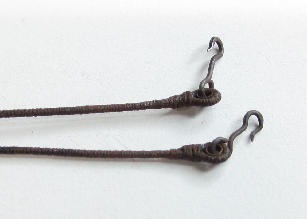
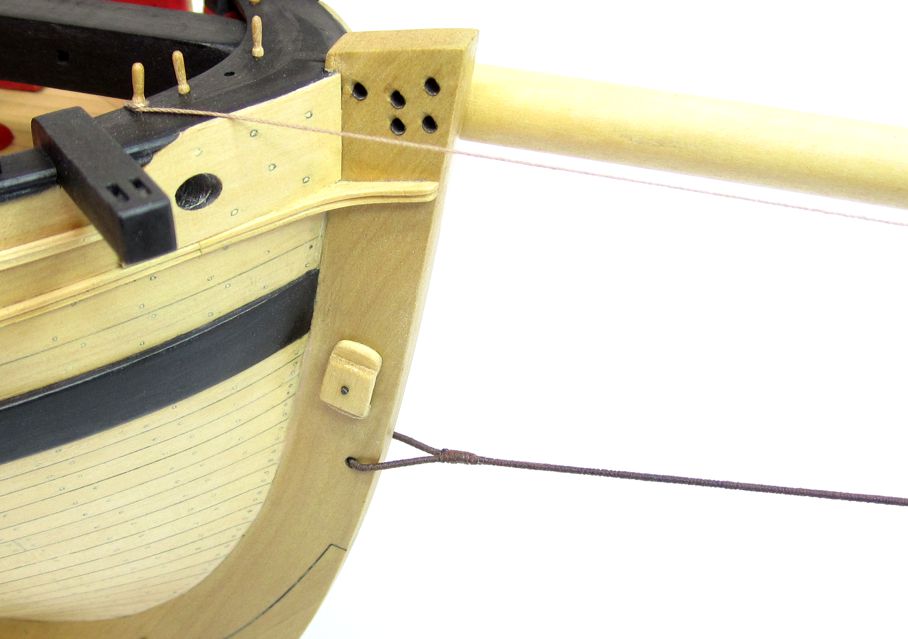
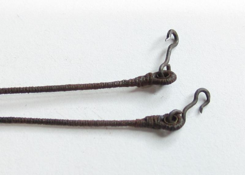
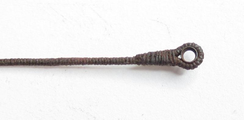
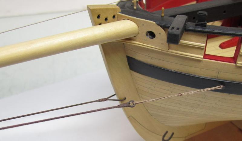
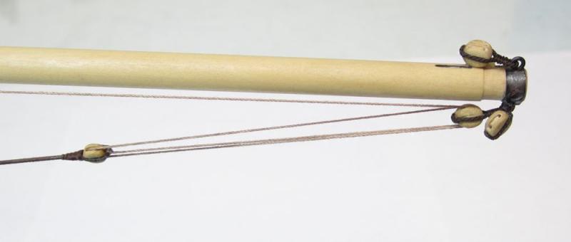
Thank You The bowsprit guys were also served their entire length. Thimbles were seized into the end of each. I used .025 brown rope for these. There are two of these and both were made at the same time to ensure they came out the same length. As mentioned earlier I am using dark brown for the standing rigging. The forward end have hooks fashioned from 24 gauge black wire. This is hooked to the eyebolt at the bow. The other end has a lanyard that stretches across to an eyebolt in the hull. Chuck
- 1,051 replies
-
- 28
-
-
- cheerful
- Syren Ship Model Company
- (and 1 more)
-
The bobstay was rigged today. I used a length of .025 dark brown rope that was served its entire length. A 3/16" single block was seized to one end while the other end was placed through the hole in the stem. That end was seized to itself as shown in the photos. The bobstay tackle was set up with .012 light brown rope. The running end of the tackle being brought inboard and belayed to the pin rail at the bow. I did not glue the belaying point at all. It is simply fixed on the belaying pin by using a simple twist of the loop around the pin's bottom. I will leave the running end a bit long for now as with all of the other lines. This line may go slack depending on the tensions from other lines etc. So not using any glue until much later (if at all) will give me an easy opportunity to loosen it at the belaying in and re-tension to suit. This will be extremely important when I turn in the deadeyes for the shrouds and set up the backstays. Once the backstays are rigged it has a tendency to make the aft shrouds go a bit slack....being able to re-tension is a huge factor so no lines will be made permanent until much later if at all. The rigging is not pulled to tight at this point. Just enough tension so it doesnt go slack. I see so many models with teh rigging so tight it causes big issues. I have restored many models that were 100+ years old and the lines were never glued permanently. This made fixing them and re-tensioning so easy that I have decided to give it a try on my models. Just pull out the belaying pin and the line is free to be re-tensioned.

- 1,051 replies
-
- 26
-
-
- cheerful
- Syren Ship Model Company
- (and 1 more)
-
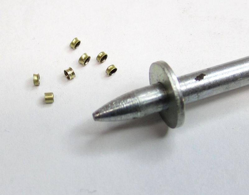
Thank Druxey Today I also mass produced a few dozen thimbles in various sizes and thicknesses. I used thin wall brass tube from Albion. They were 1.5mm and 1.2mm and 1.7mm in diameter. I have no idea which will be used where yet but making a bunch now will save me from having to stop while rigging. Blanks of various thickness were cut and then I used the blunt punch shown to shape each end and flare it. Just a few light taps will do it. Then you can blacken them or even paint them whatever your preference is. You can see one blank before I used the punch on it in the lower left hand corner. You can see teh difference between the others pretty clearly. Chuck
- 1,051 replies
-
- 25
-
-
- cheerful
- Syren Ship Model Company
- (and 1 more)
-
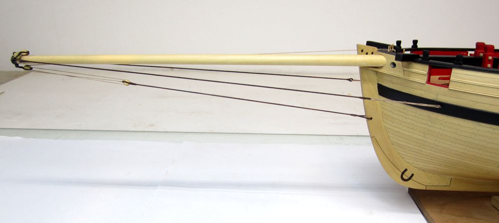
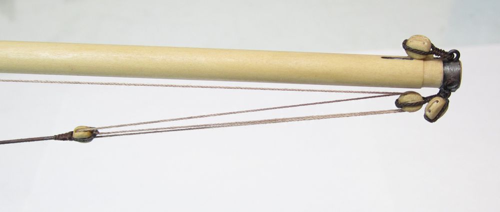
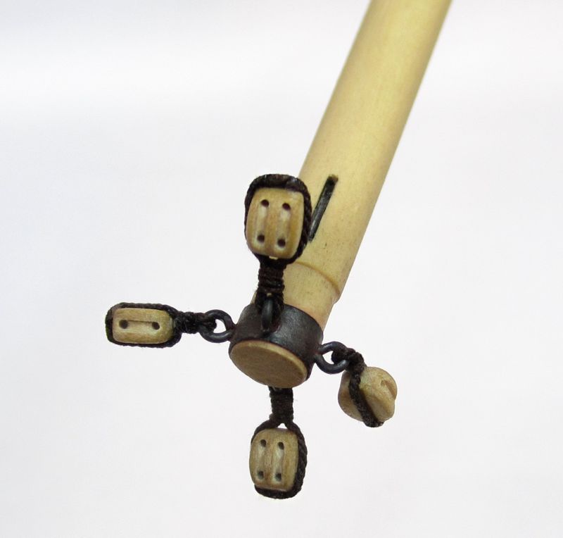
Rigging has begun. I still havent made the long guns at the bow but I figured I needed to break the ice and at least add the blocks to the tip of the bowsprit. There are 4 blocks. Two singles and two doubles that are 3/16" long. I am using dark brown for standing rigging and light brown for running rigging. Next up will be the bobstay with tackle and then the bowsprit guys. It has been a long time since I rigged a model. I figured why procrastinate. In some cases, these blocks are hooked to the ringbolts. But I am just seizing them. There are so many different configurations used on Cutters from this time period. And yes...I am using all Syren blocks and rope of course. Its a brutal close up photo but it looks fine in actuality. Onward and upward as they say.
- 1,051 replies
-
- 24
-
-
- cheerful
- Syren Ship Model Company
- (and 1 more)
-
There are also many "chain" laser cutters out there. But you most likely have to use their available materials. see here http://www.ponoko.com/laser-cutting and https://www.pololu.com/product/749
-
I am willing cut small jobs when the time permits. I would encourage folks to contact me for availability. For example, right now I am swamped and couldnt possibly take a small job for laser cutting and have one such custom job on my to-do list. I just wont get to it til early next month at the soonest. If time isnt a factor then please let me know what you need. Provide me with either a Corel Draw file or a DXF file of the parts. I can talk you about specifics and the need to always have to adjust the drawings after I get them. They will always need to be adjusted for the kerf of the cut depending on what type of wood you choose. If you want the stuff sooner, You can contact National balsa. They have an excellent laser cutting service and I used them all the time before getting my own equipment. But they will only use the woods they have in stock. Basswood, Maple, Cherry and lite ply.....amiong a few other things. See here for the custom laser cutting services at National balsa http://www.nationalbalsa.com/laser_cutting_s/8.htm You would probably have to double your $2000 estimate for getting a laser cutter of your own the needed software and accessories. That is if you want to cut anything thicker than 1/8" basswood with accuracy and a decent cut. Chuck
-
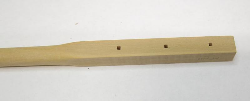
They were drilled out on a drill press first with a normal bit (round). Then I just took a #11 xacto blade and notched out the corners by eye to square them off. They are 1/16" square. They are not square all the way through. Just deep enough that after painting you would think they were squared up all the way through. They are square only about 3/64" deep into the hole. Thanks for the kind words guys. Chuck
- 1,051 replies
-
- 8
-
-
- cheerful
- Syren Ship Model Company
- (and 1 more)
-
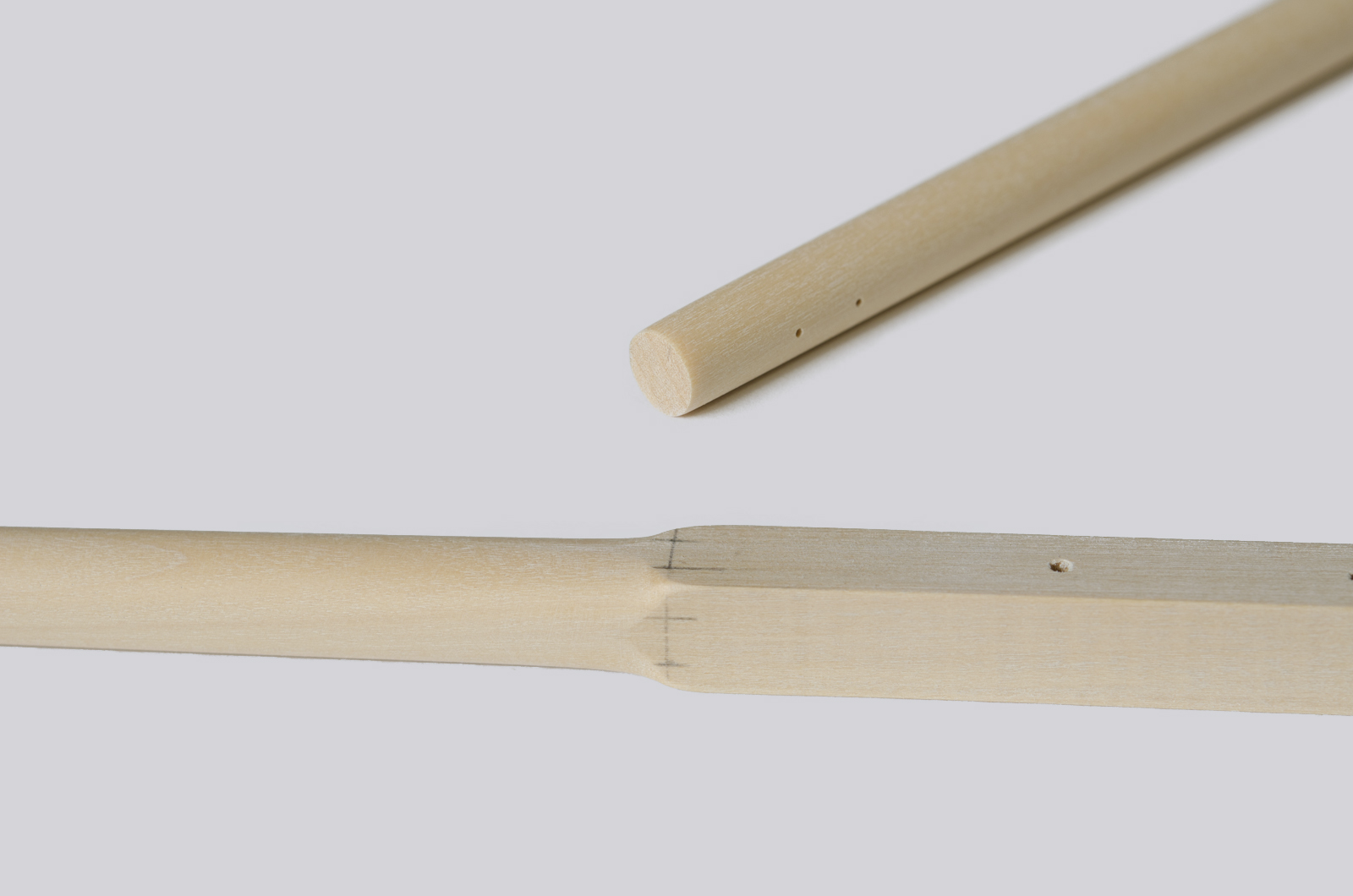
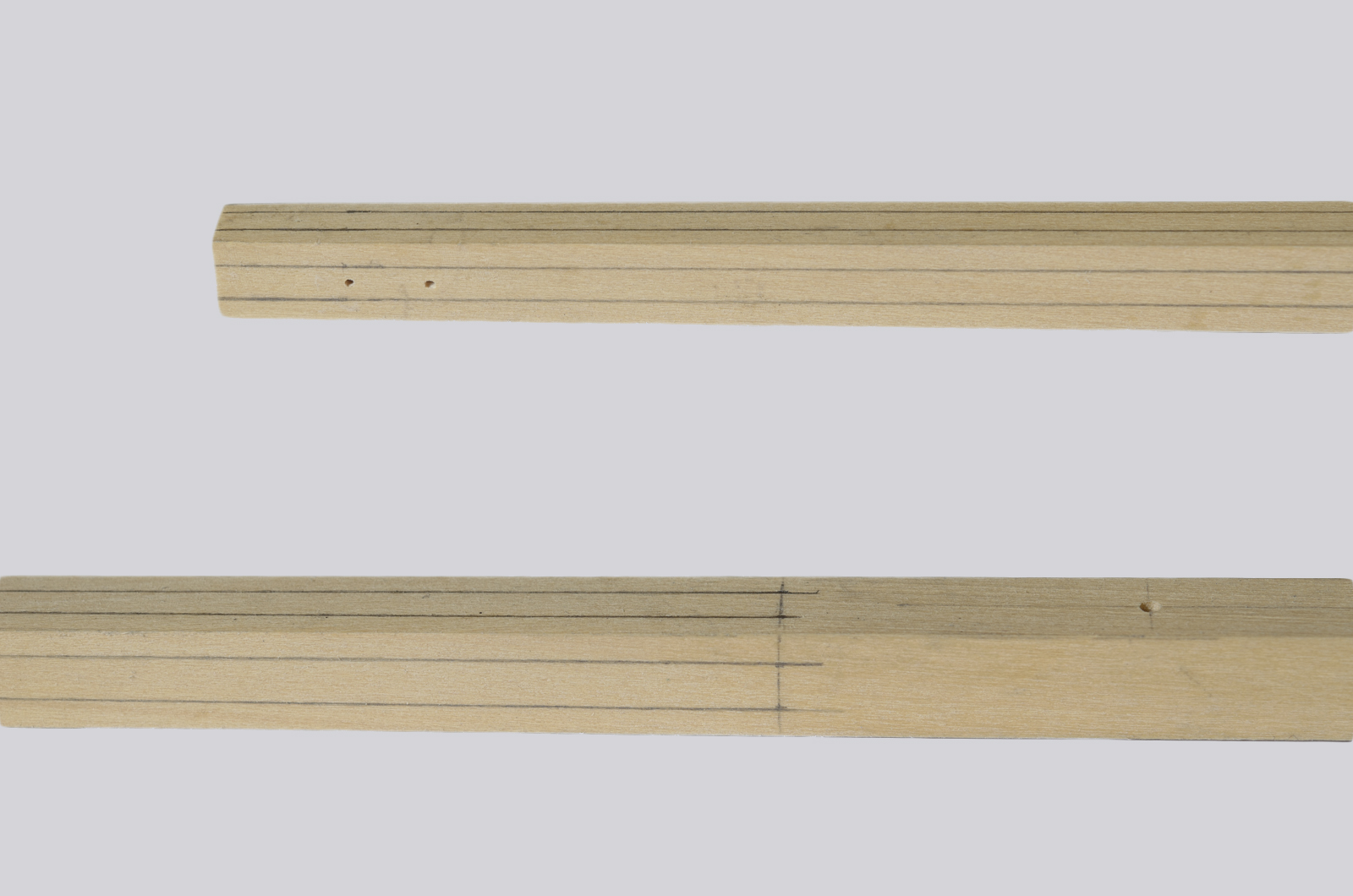
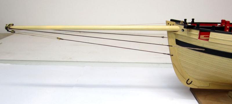
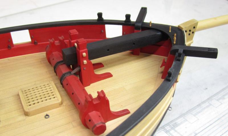
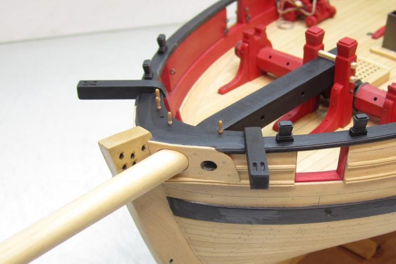
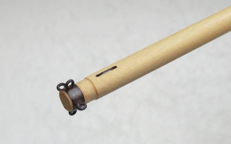
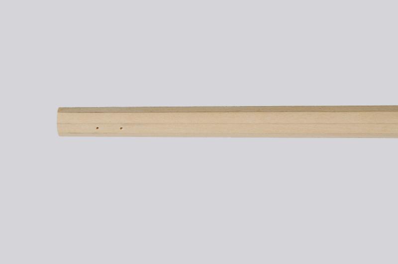
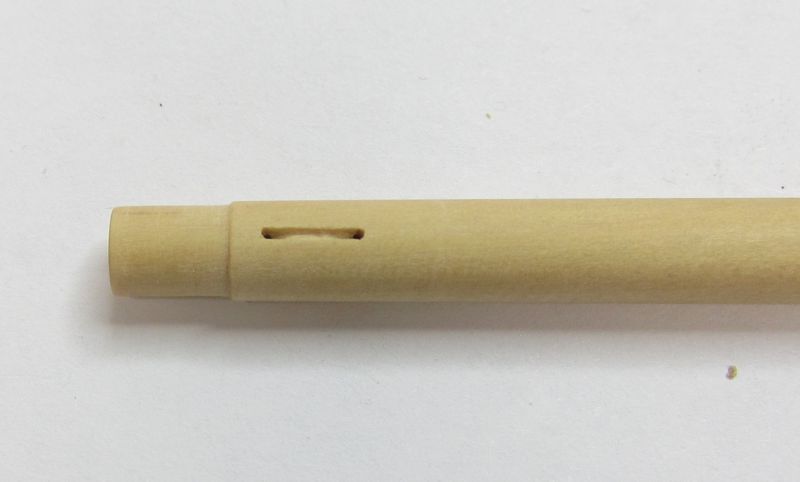
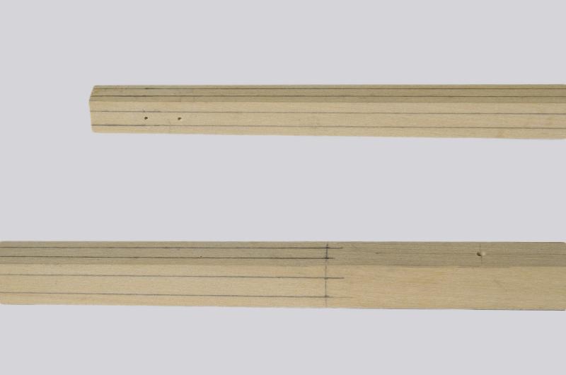
To make the bowsprit....start with a square stick of boxwood 5/16" x 5/16". The inboard section will remain square. The outboard side is rounded off and tapered. There are three square holes on the inboard sides. But these start out as round holes made on the drill press while the entire stick is still square. There is also a sheave on the outboard end. The holes for this simulated sheave are also drilled while the stick is square. Then the outboard end is measured and marked for the 7-10-7 ratios to make it an octagon. From an octagon it is then made round. There are many way to do this. Mini-plan...files...by hand....then rounded off on a lathe or even chocked in your hand drill. Then I made it round...in my hand drill...and taperred it to match the plan while doing so. Once that was done...the simulated sheave on the outboard end was detailed. I used a #11 blade to connect the holes and carve it out a little. Then mini-files were used to round off the simulated sheave. Later I will darken it with pencil. The three inboard holes need to be made square...again there are many way to do this. I decided to just use my #11 blade to carefully square off the corners. The inboard portion will eventually be painted black. The outboard end also has a metal band with four eyes around it. This was made from paper. You could use art tape or even brass if you wanted. Again there are so many choices. It was painted black and weathered so it looked differently than the wood elements painted black. Then it was mounted in the hole at the bow and the fit tweaked. Once it looked good, the bowsprit step was slid onto the inboard end. You wouldnt be able to slide the bowsprit in position if the step was already glued in place. So this is a bit tricky. But soon after I was able to get it all in position and glued securely. Then I touched up the paint and cleaned it up. Next up the long guns can be positioned....but I am unsure of I will add them. They will look very crammed in there. I will have to contemplate that for a bit.

- 1,051 replies
-
- 48
-
-
- cheerful
- Syren Ship Model Company
- (and 1 more)
-
Yes just start a new one and I will delete your old one. All of the photos are missing anyway. So be sure to upload them using the photo upload button on the site when you make each post rather than host them elsewhere. Chuck
-
The standard practice is to put your wales in first. Measure off the plans. This establishes the correct run of the planks across the hull. I thought that was your hull. That isnt optimal at all. Then you plank from the wales up......and then from the wales down. Even if its just the first layer of planking for the wales. Best to put the wales in first. Whoever's hull that is will have a funny looking wale at the bow and stern. It doesnt look like the correct run of planking was established. Measure from the shear down to the top of the wales and the bottom of the wales....marke it off on each bulkhead and plank them first. It will save you a lot of trouble....BUT yes....you can spile all of the planking. Absolutely. But its always always good practice to put the wales in first. If you look around this site you will see plenty of hulls where they didnt do that and then when it came time to add the wales as second layer....they did in fact measure from the shear only to discover that the wales will not follow the run of the first planking layer they did at all. Which looks really odd when done. Chuck
-
That is quite the odd shaped hull at the bow. But yes you can spile all of the planking. Usually it is those under the wales that need it most but looking at your bow shape....I am truly at a loss. So yes probably. I cal tell from teh photos that the bulkheads were not faired nearly enough. That probably contributed to the odd shape. Chuck
-
Its great to see you back again....enjoy the project and dont hesitate to ask me any questions. Chuck
-
Its simple really....you determine the max width for a plank by choosing the scale widths that were actually used on that vessel. Its not a random choice. Should you end up with an odd number of planks after doing so, then just make one belt with one less strake in it. They need not be all the same. But depending on the size of the ship and country of origin....choose the correct width accordingly. It could be eight inches....it could be 10 or 12". It depends on the ship. The period etc. It doesnt have to be equally divided.
-
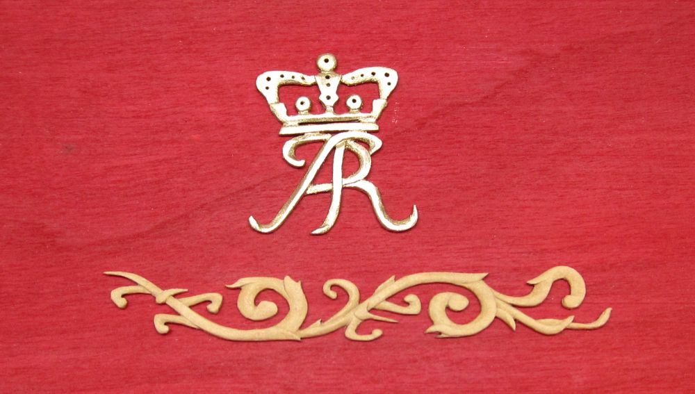
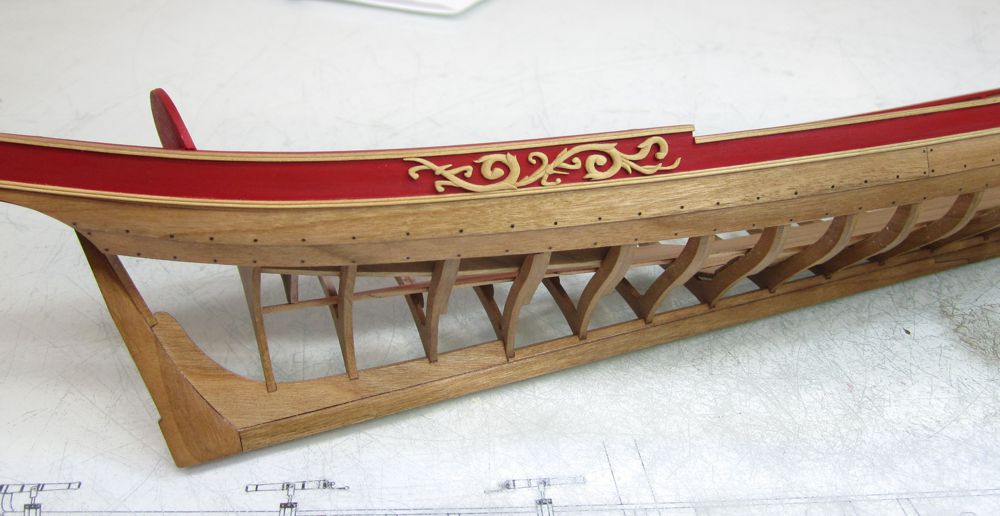
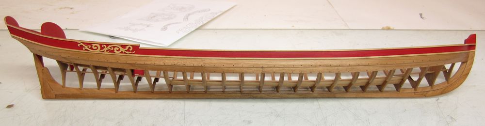
Thanks Pat. Yes I agree, I think I am going to go natural. One of the guys in my club said if I was going to the trouble to carve the boxwood rather than use castings I might as well show folks that its a delicate hand carved piece by not covering it up. I agree with him and will now move ahead with the others over pieces when time permits.
- 269 replies
-
- 13
-
-
- Queen Anne Barge
- Syren Ship Model Company
- (and 1 more)
-
US Brig Syren by Gahm - Model Shipways
Chuck replied to Gahm's topic in - Kit build logs for subjects built from 1801 - 1850
Very nicely done. I hope you enjoyed the little mini-kit. Its a rewarding project and you did a marvelous job with it. Chuck -
I know the feeling. I already have two in college. But my oldest got a free ride though. In fact they pay him to go. These kids are too smart to be mine. I dont know what happened there. Maybe I will get lucky again. Probably not. She wants to be a pathologist. How many years is that??? Cha-ching.......a forensic pathologist. Go figure. Chuck
- 1,051 replies
-
- 5
-
-
- cheerful
- Syren Ship Model Company
- (and 1 more)
-
I have been suffering for a lot longer than you think......I really cant believe it though. I am blessed. She is very smart like my boys and is looking at Princeton too!!!! I might have to sell a kidney. I am so very very proud of her. Chuck
- 1,051 replies
-
- 11
-
-
- cheerful
- Syren Ship Model Company
- (and 1 more)
-
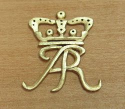
No sweaters for me. The agony.....besides my toothache.....its whether to gild or not??? I am leaning towards no gilding. I do like it but its just me. It also shows every last surface pimple and carving screw up. But it is a royal barge. I think I like the way the carvings look with just WOP applied. Which means I must carve another queen Anne cipher. Oh well!! The close-ups are also brutal....the smaller image looks more like the gilded example in reality. It looks rather nasty in that large photo. Chuck
- 269 replies
-
- 36
-
-
- Queen Anne Barge
- Syren Ship Model Company
- (and 1 more)
-
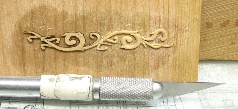
Boxwood carving for the barge in progress. Using a #11 blade. Its half done. Left side shows the laser cut blank while the right side is almost there. The blanks are glued to a piece of scrap with elmers glue. In this case I just used a glue stick. Make sure its really glued down good. Especially the ends of the thin parts that are susceptible to breakage. I sandwich the glued up piece with another scrap sheet and clamp them together so the piece stays flat and doesnt curl up. The blanks are just 1/32" thick and sandwiching keeps them flat so all the surfaces glue up nicely. Leave them overnight to dry really good.....now you are ready to carve. The finished carving is removed from the base by just dumping it face-first into a bath of 90% rubbing alcohol for 5 or 6 hours. They usually just fall right off the base. Let them air dry and you are good to go. When you dont have lots of time to spend on the model its good to keep these carving blanks around the shop. You can easily spend a half hour or 45 minutes doing a little at a time. There are nine such pieces in this kit that will need to be carved. But dont worry .....a resin casting kit will be available for those who dont want to carve them or give this a try. But I urge to to do so...its a lot of fun and addicting. The guys in the club cant get enough of them to play around with. Chuck
- 269 replies
-
- 22
-
-
- Queen Anne Barge
- Syren Ship Model Company
- (and 1 more)