-
Posts
9,703 -
Joined
-
Last visited
Content Type
Profiles
Forums
Gallery
Events
Everything posted by Chuck
-
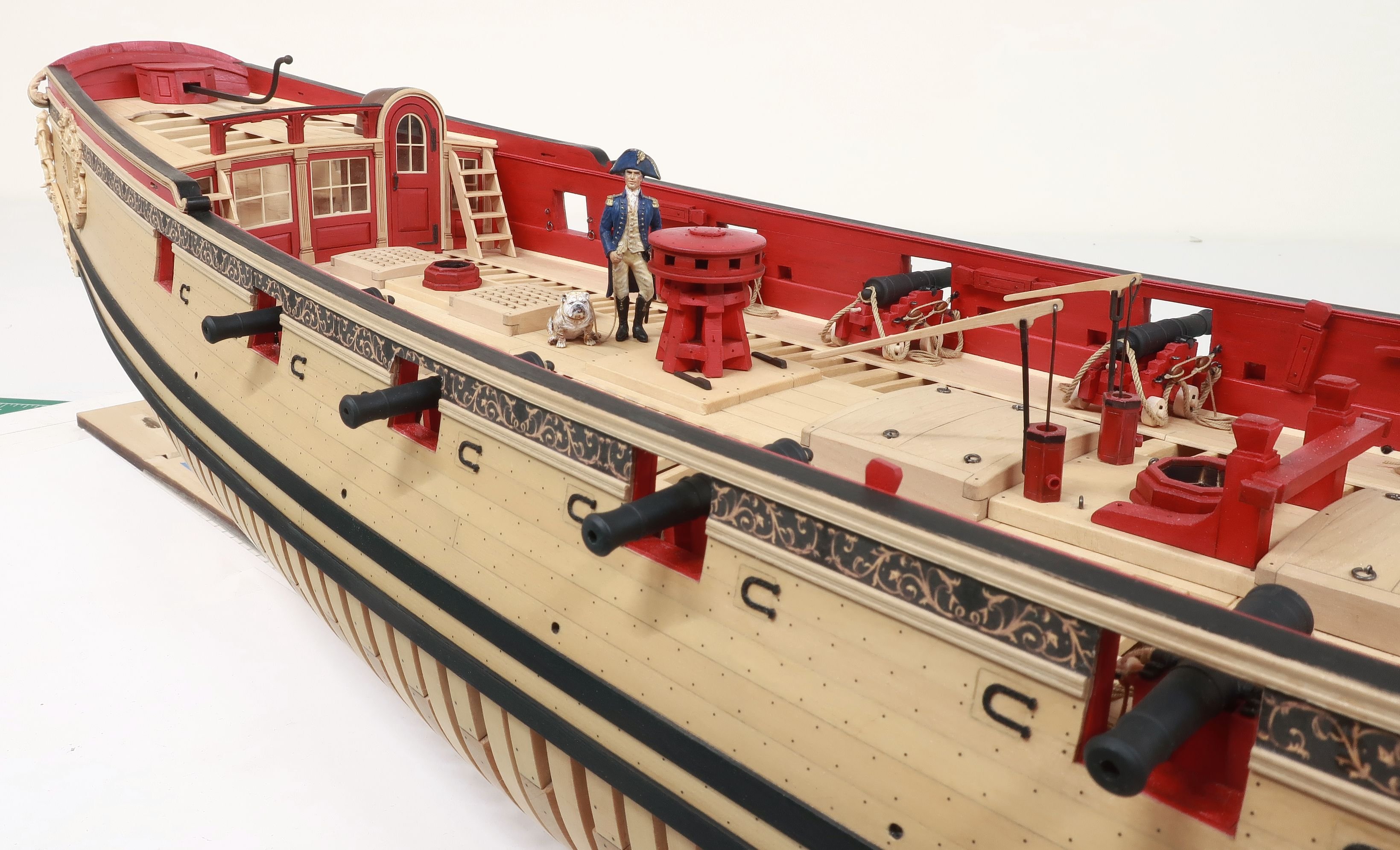
That looks fantastic...It looks like you spent all day painted those friezes.
- 109 replies
-
- 18th century longboat
- model shipways
-
(and 1 more)
Tagged with:
-
Dont be afraid to sand the heck out of it. You can sand all of that off and restain it. The planks are thick enough. Try t again but make sure you use a mixture of more natural stain vs golden oak. I would start with something like a 20 % stain mixture to 80% natural. See what happens. You can remove that stained layer if you just sand it off. Then sand it with a very fine 400 - 600 wet dry paper. Then apply the stain mixture. Chuck
-
Yes it should be...This way the caprail overlaps slightly on the outboard side only. The inboard side is flush. But that means you must go much thinner than 3/32" wide. The bulkheads should be sanded down to about 1/16" wide at the caprail or even less. The model will be surprisingly strong. Shoot for 3/64" wide along the top of the bulkheads.
- 162 replies
-
- 18th century longboat
- model shipways
-
(and 1 more)
Tagged with:
-
I am not sure what you mean...lowered as far as recessed. Yes you can do that. You can create basically any shear you want within reason. Chuck
- 162 replies
-
- 18th century longboat
- model shipways
-
(and 1 more)
Tagged with:
-
Al You can use the plans and use CNC to cut out the parts. As long as they are for your own personal use on this project then feel free to use any method to cut out the parts. As the hobby matures, folks are starting to use new tools and technology. Who are we to stand in the way. I happen to prefer a sharp chisel or a scroll saw but other now find CAD and CNC or even laser cutting just as much a part of the process. Its no different than someone using a Sherline Mill or Lathe vs. a jewelers saw and chisel. The project is an introduction to scratch building and scratch building techniques. CNC is just one of those techniques that are newer. CAD and CNC are fast becoming a fun part of this hobby for lots of people. They should be made to feel welcome here. So again I will welcome you to the group and forum. Build away and enjoy the project. The only disclaimer is that it be for your own personal use and you cant distribute cut parts to other builders. I will enjoy watching you progress and dont hesitate to ask me any questions. You have the complete blessing and authority from ADMIN and Owner alike. Chuck
-
Looking great...certainly take your time with that thinning down. That is an important step. Nothing worse than a very thick transom. Try and get into those nooks and crannies. It will pay huge dividends as far as the final model is concerned. Take your time. Chuck
- 2,191 replies
-
- confederacy
- Model Shipways
-
(and 1 more)
Tagged with:
-
Wonderful work. Its really coming together. Chuck
- 175 replies
-
- washington
- galley
-
(and 1 more)
Tagged with:
-
Nope...much smaller. Only large enough for the .008 line to pass through. I use a #77 or # 78 drill. Chuck
- 162 replies
-
- 18th century longboat
- model shipways
-
(and 1 more)
Tagged with:
-

cable laid vs rope (left vs right twist)
Chuck replied to davec's topic in Masting, rigging and sails
Jerry...you asked Once you have made three left-hand ropes, you then twist these to achieve the right-hand cable. Do you have to tension the laid-up left-hand rope in the opposite direction before you twist them into the right-hand cable? The answer is yes...Twist them even more to create a tight twist that will want to untwist when you are done. This "wanting to untwist" creates the tension when you wind all three in opposite direction afterwards. Its the same as when you started with the smaller ropes....You must twist the individual strands first...otherwise they have no tension.....which will soon be equalized when you twist all three together in the opposite direction. You see, when folks just place 9 strands on a rope walk (3 on each without having turned them into rope first) and just do the initial twist of the nine.....there was no tension to keep those initial twisted three threads together as rope. In fact, if this is what you have tried as Michael has.....try this experiment. Before you twist those nine strands into rope after completing the initial twists...just cut them free and see what happens to them. You will soon find that they quickly unwind. This doesnt create a good large cable because it will always want to unwind from its core... Yes it saves time, but it doesnt make the best rope. This will happen on any machine or ropewalk. It usually starts on the ends that were cut, even with a sharp blade. The three larger ropes untwist just a little bit......then the individual strands in each of those that were not laid up properly begin to untwist...then it just creeps along the whole length of rope in short order as you handle the ends with your hands. Hope that makes sense. Its much easier to show a person while they are in my shop than explain it in writing. Chuck -

cable laid vs rope (left vs right twist)
Chuck replied to davec's topic in Masting, rigging and sails
Yes it did get smaller but its a much better rope. That will happen. If it still unravels its because your using multiple lines on each and twisting them first. Those wont stay twisted because you never twisted them individually first to create tension. That being said, it will still hold together well enough. For example, when I make a larger cable I first make three smaller cables with tension so they wont unwind. Then I take those three and make the larger rope. You end up with an opposite twist however so you have to remember to correct that by creating the first three strand with the opposite twist you will eventually require. I do understand what Gaetan is saying though. Standing while twisting is very awkward. Better if that end is on a table top as is mine. Then you are able to control the "walking" of that end better. You will also get a better "feel" for that tension. I am sure his more complex rope walk works great as well. But like I said....simple is just as good. I dont use any weights at all and I simply slide the end on a table and "feel the tension". I can adjust if needed. It will be difficult to achieve the same results over and over again without that sort of control. Standing up like that will make it very hard to replicate over and over again. Chuck -

cable laid vs rope (left vs right twist)
Chuck replied to davec's topic in Masting, rigging and sails
Looking at your rope I would recommend doubling your initial twists and then doing the same with the twisting of the three strands together. Chuck -
Thanks I doubt the treenails would be seen under the paint. But either wau it couldnt help to seal the wood first before painting. The Wipe on Poly should be fine. No primer is needed. Chuck
- 162 replies
-
- 18th century longboat
- model shipways
-
(and 1 more)
Tagged with:
-
Plans are only available with the kit. You can buy one at Modelexpo-online.com or on ebay. Chuck
- 162 replies
-
- 18th century longboat
- model shipways
-
(and 1 more)
Tagged with:
-
Thats rather messy. I choose to place a few dozen on a some paper towels and then dip another in the stain. Then roll them around with it. It gets just the right amount on them without clogging the sheave holes. Chuck
-
No I built the longboat in boxwood and in bass. The pinnace in Boxwood and now in holly. Others from my club have built it in pear. Its just a personal decision based on teh color. Holly is super easy to work with. Especially with the planking. It bends so easily. I have not finished that version yet. I was curious what a fully white or "whitish" model would look like. Maybe like bone. So I gave it a shot for fun. Still have it but unfinished. Maybe I will offer it up to someone else to finish it. Dont know if i will ever get around to it. Chuck
-
i wouldnt try and bend it it...better to cut it from a wider sheet....but you are doing an outstanding job. Chuck
- 137 replies
-
- finished
- model shipways
-
(and 1 more)
Tagged with:
About us
Modelshipworld - Advancing Ship Modeling through Research
SSL Secured
Your security is important for us so this Website is SSL-Secured
NRG Mailing Address
Nautical Research Guild
237 South Lincoln Street
Westmont IL, 60559-1917
Model Ship World ® and the MSW logo are Registered Trademarks, and belong to the Nautical Research Guild (United States Patent and Trademark Office: No. 6,929,264 & No. 6,929,274, registered Dec. 20, 2022)
Helpful Links
About the NRG
If you enjoy building ship models that are historically accurate as well as beautiful, then The Nautical Research Guild (NRG) is just right for you.
The Guild is a non-profit educational organization whose mission is to “Advance Ship Modeling Through Research”. We provide support to our members in their efforts to raise the quality of their model ships.
The Nautical Research Guild has published our world-renowned quarterly magazine, The Nautical Research Journal, since 1955. The pages of the Journal are full of articles by accomplished ship modelers who show you how they create those exquisite details on their models, and by maritime historians who show you the correct details to build. The Journal is available in both print and digital editions. Go to the NRG web site (www.thenrg.org) to download a complimentary digital copy of the Journal. The NRG also publishes plan sets, books and compilations of back issues of the Journal and the former Ships in Scale and Model Ship Builder magazines.


