HOLIDAY DONATION DRIVE - SUPPORT MSW - DO YOUR PART TO KEEP THIS GREAT FORUM GOING! (Only 75 donations so far out of 49,000 members - C'mon guys!)
×


Chuck
-
Posts
9,674 -
Joined
-
Last visited
Content Type
Profiles
Forums
Gallery
Events
Everything posted by Chuck
-
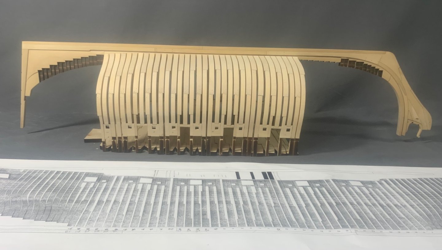
 Time to put some meat on those bones. That a great foundation for planking.
 -
That looks very good. Well done.
- 131 replies
-
- 2
-

-
- Medway Longboat
- Syren Ship Model Company
- (and 1 more)
-
Nice start
-
It looks good. BUT its odd to me why you would glue the black strake on before you glue the second layer of wales on. And the 1st layer above the black strake. Was there a reason why you decided to do it that way? When you sand the layer above the black strake it may very well screw up the black strake. Just me thinking out loud. But I suggest to stick with the order mentioned in the monograph chapters. You may run into issues later on.
-
Nicely done
-
The contemporary model is the original primary source for the carvings. It was a very important model and made at the time the original ship existed. So there is absolutely no reason to believe they are an accurate representation of what actually appeared. You cant get better than that. To use anything else would be far more speculative and unlikely. I would absolutely encourage you to start your own build log so any questions you might have would be asked there. It would also be better for the group to see your progress. Join the group....dont be shy. Chuck
- 1,784 replies
-
- 5
-
-
- winchelsea
- Syren Ship Model Company
- (and 1 more)
-
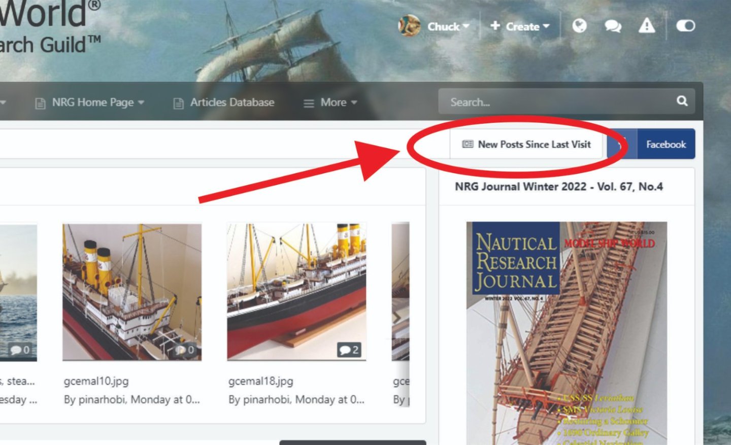
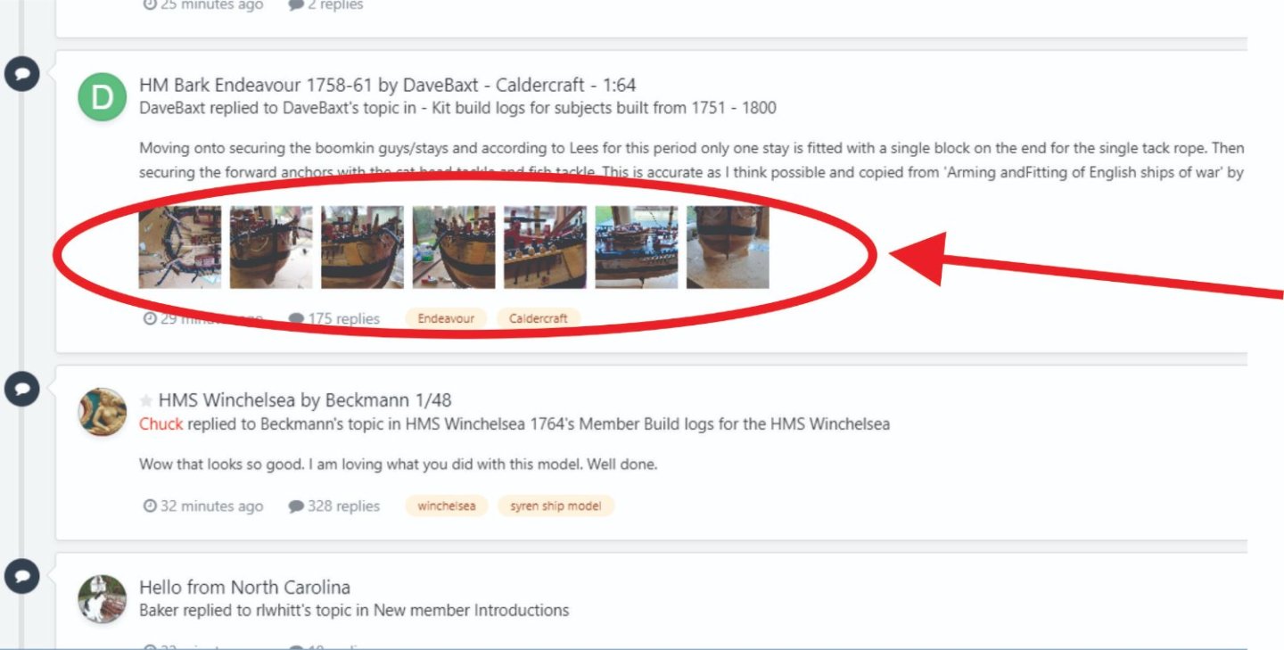
Dont forget... if any of you didnt know, that you should see a link at the top of your page on the right side. A great way to instantly see all the new posts so you can easily scroll through them. It even shows pictures if there were any. A great way to quickly scroll through and see the good stuff. Its the first thing I click on when I visit the site.
-
Wow that looks so good. I am loving what you did with this model. Well done.
-
Excellent progress!!
-
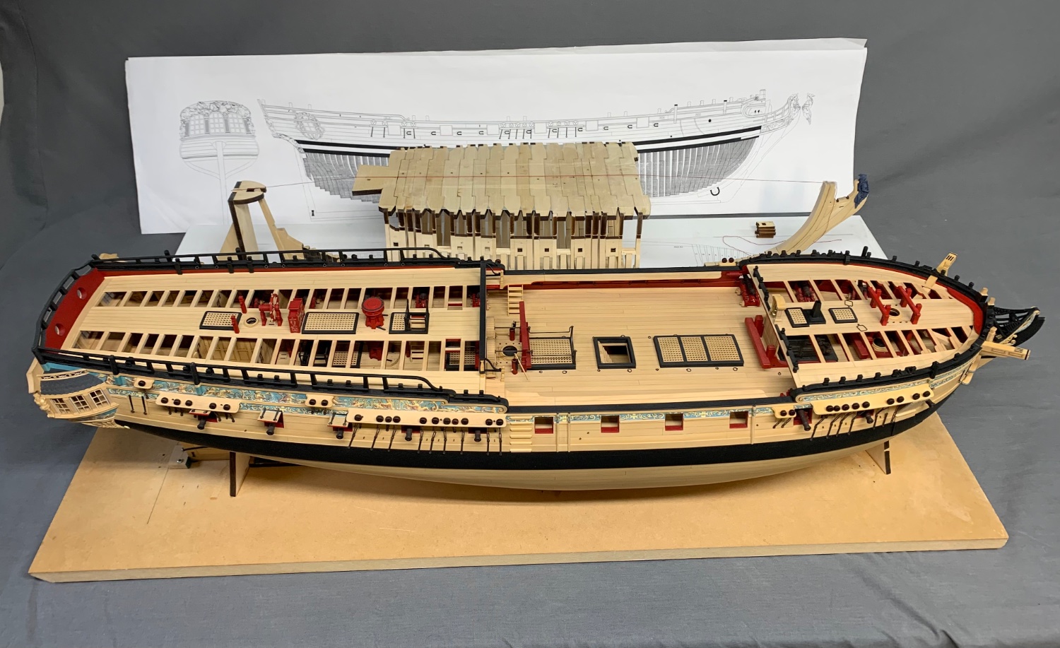
There is a lot of distortion but here is a picture of Mike’s Winnie next to the speedwell for a size comparison. The Speedwell is about 7” shorter at 3/8” scale even though the picture makes it seem like more. That is after all the framing is done. Only 8 more square frames to go…since this picture was taken.

-
If you spray them….do only a light spray from far away. It really doesnt have to be soaked which I see some folks doing. Just a light spray of matte fixative from a couple feet away.
-
Sixth time was a charm! That looks pretty darned good to me. Chuck
- 217 replies
-
- 1
-
-
- medway longboat
- Syren Ship Model Company
- (and 1 more)
-
Very nice. That looks fantastic. Patience pays off. The rest of the deck planking is a piece of cake!
- 840 replies
-
- 4
-
-
- winchelsea
- Syren Ship Model Company
- (and 1 more)
-
Beautiful.
-
For deck planking on top of a base false deck it would be fine. Being just a hair thinner shouldnt effect the gun height too much. But it wouldnt work for hull planking unless you plank two layers. They are too thin for use on a single planked hull. Hull planking on a pob hull with thin 1/32 planks is not a good idea unless you fill all the spaces between bulkheads with balsa to make it solid.
-
That looks very good Gary. It will be a relief once its all done. Dont be afraid to sand the hell out of it. Chuck
-
It doesnt mater really. The two halves were designed so you can cut the top of the “striped barrel” down as much as you need. As long as you leave just the tiniest bit above the deck beams you are good so you can position the partners. Then the top capstan can just fit i nto the remaining space on the partner. If there is a small gap it doesnt matter…nobody will see it.
-
So close to the finish line. It looks great.
- 607 replies
-
- 2
-
-
- winchelsea
- Syren Ship Model Company
- (and 1 more)
-
Either way would work. Mine ended up more parallel. But its more important to just keep them neat. It really all depends on how far apart your main rails ended up and what the angle into the stem ended up like on your model. It will probably be different on everyones model…. all be it slightly. The more you have to tweak the angle on those notched knees to match the angles…the more different the angles of the battens will be. Its a very complex area.
- 1,784 replies
-
- 4
-
-
- winchelsea
- Syren Ship Model Company
- (and 1 more)
-
Looking good. Just remember how much you will miss planking when uts all done!
-
Very nice progress. Neat and tidy.