-
Posts
9,663 -
Joined
-
Last visited
Content Type
Profiles
Forums
Gallery
Events
Everything posted by Chuck
-

US Brig Syren by Gahm - Model Shipways
Chuck replied to Gahm's topic in - Kit build logs for subjects built from 1801 - 1850
Wonderful!!! Nicely done. -
Yes but that will be separate…not a chapter per se. it will be a whole new mini kit..one thats pretty involved I think. Mounted on two spare topmasts like this. I am not considering it as part of the winnie project because it could also be a stand alone project. I am looking forward to your build log…start it up already!!! Mike I think he was referring to Chris Watton of Vanguard Chuck
- 1,784 replies
-
- winchelsea
- Syren Ship Model Company
-
(and 1 more)
Tagged with:
-
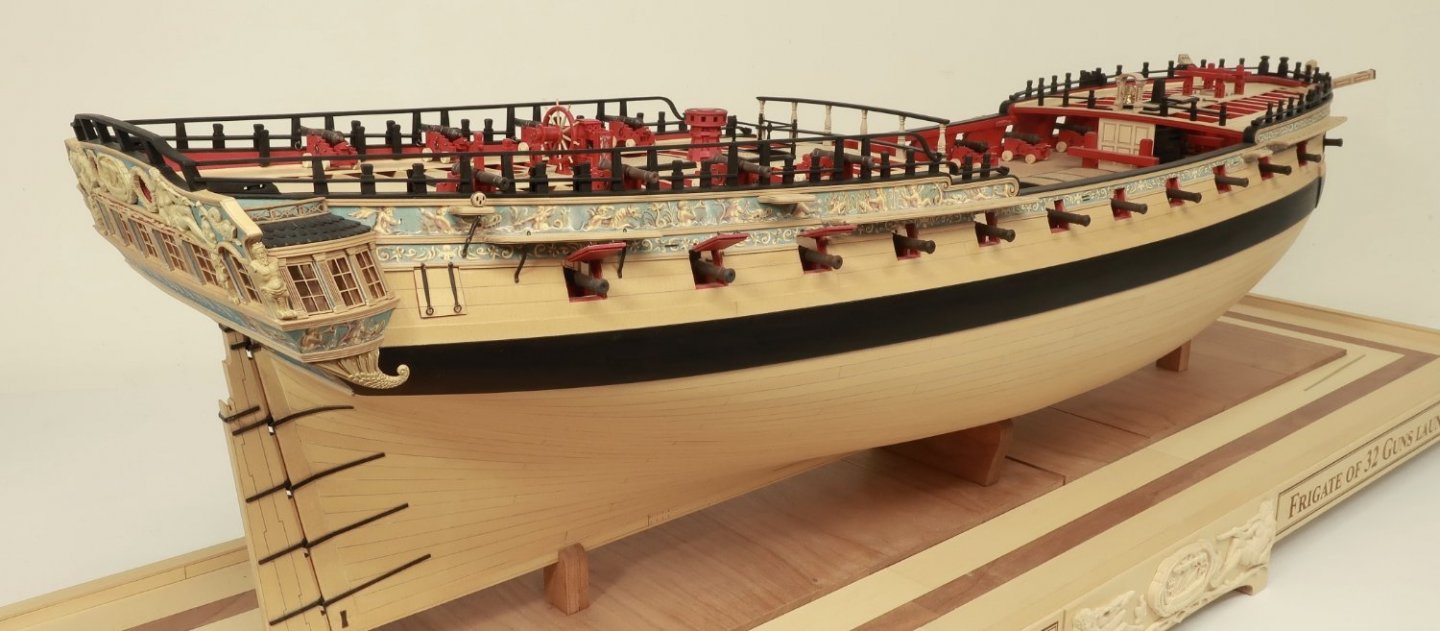
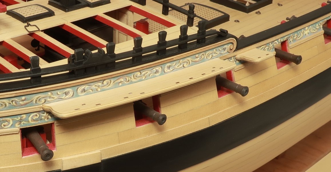
It is bitter sweet as always. But I am eager to start something new. We are in the home stretch now!!! Will be making the fenders next and entry ladders. Then its on to the swivel guns. That will complete the exterior except for the lantern. Then we will move inboard again to complete the waist area with gangboards. That will finish chapter 11. Chapter twelve is the headrails and lantern....Finished.
- 1,784 replies
-
- winchelsea
- Syren Ship Model Company
-
(and 1 more)
Tagged with:
-
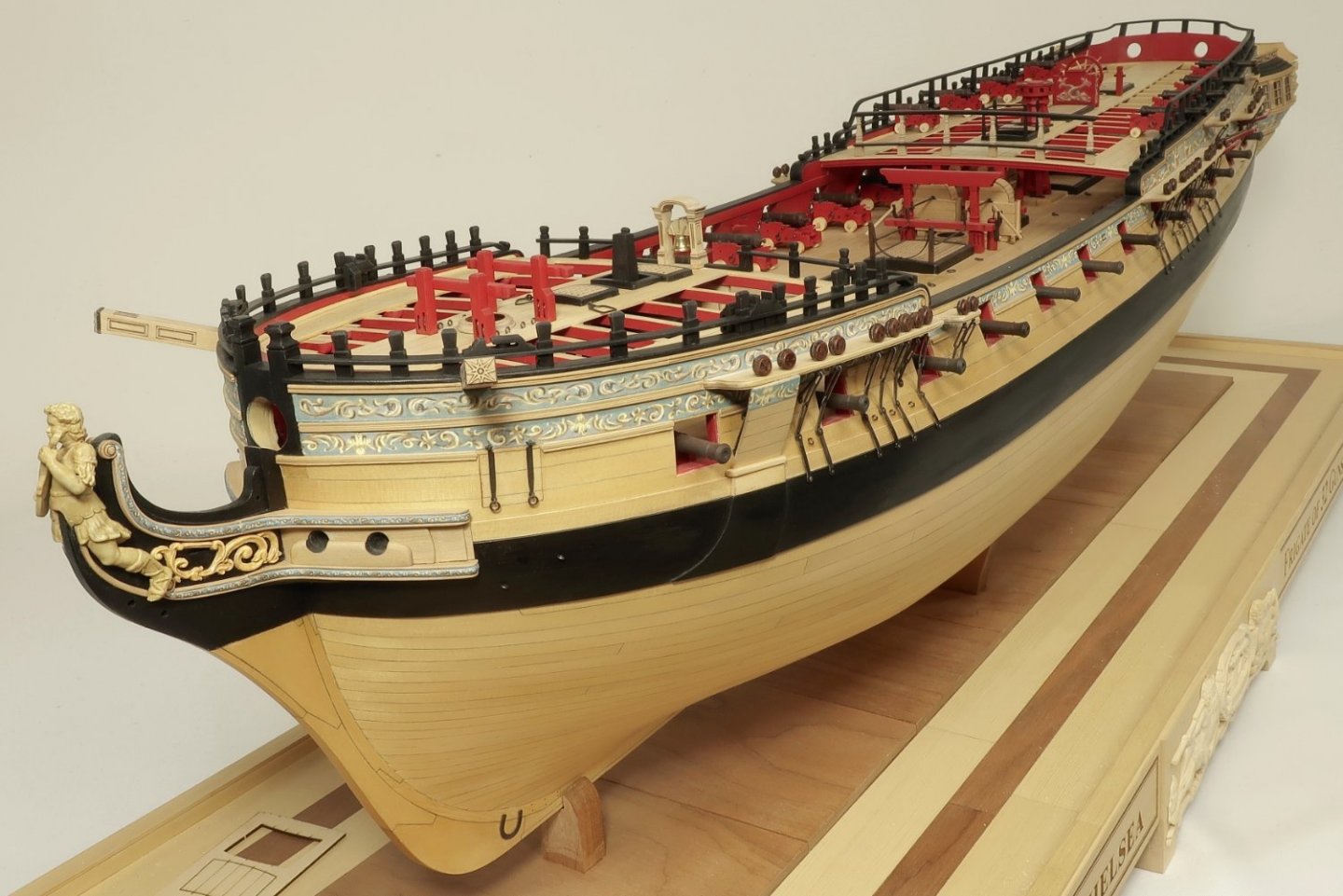
The darker deadeyes are growing on me. I think I also fixed my camera settings...hopefully these are better. But I did finish the deadeyes and chainplates on the port side. I also started a test on the Billboard. Thats the board that covers the first two chainplates at the bow. Its just above the anchore lining. Basically its a 5/32" x 5/64 strip that was rounded off on the ends and the edges as well. This was placed above the anchor lining and cut so the ends overhang the sides of the anchor lining just a bit for and aft. The billboard is laser cut and etched with planks already. There is also a laser etched rabbet on the back side where it fits against the channel. The bottom edge is beveled to sit flat on top of the strip I just mentioned. Then I rounded off the top edge and applied the frieze. I am not sure if I should extend the frieze all the way up on the billboard as I left just a sliver natural to match the thickness of the channel. I will sit on that for a bit before deciding. Anyway....some pictures.
- 1,784 replies
-
- winchelsea
- Syren Ship Model Company
-
(and 1 more)
Tagged with:
-
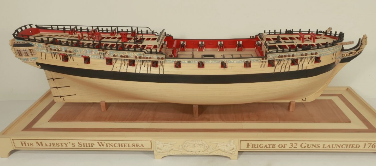
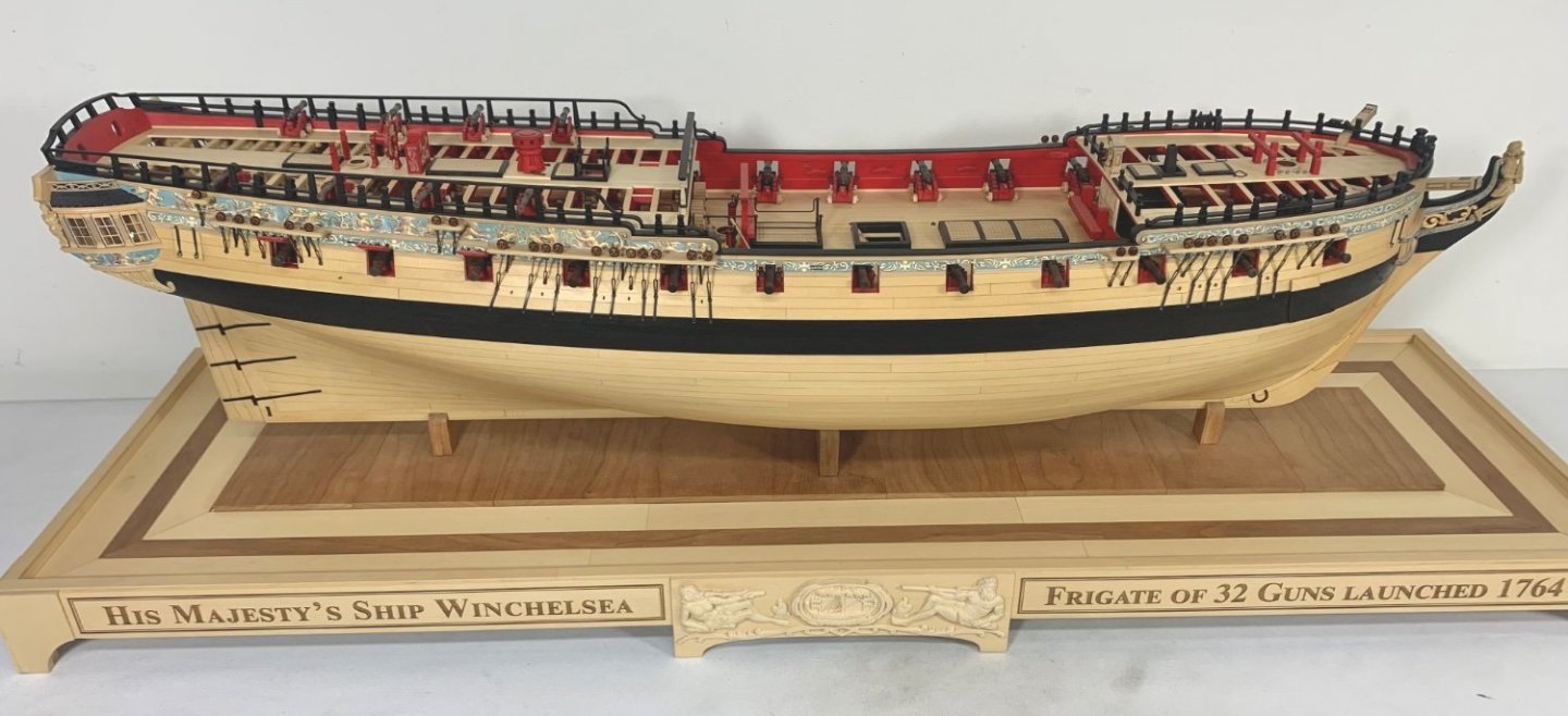
I finished the 6mm deadeyes and chainplates on the Starboard side. Its the same as doing the 5mm deadeyes except these chainlates also get an additional strap on their ends. It extends over the black strake and onto the wales. In addition, there are two lengths of center links. As you work your way aft on the channels you will need to switch to the longer link. I found that the fore channels needed the longer links for almost all the deadeyes. Here is how the model looks today. I also added the eyebolts between the chainplates as indicated on the plans. Two photos of the same thing….one from my cell phone which I am testing. Trying to adjust values etc. sorry for redundancy but I need to see them side by side.
- 1,784 replies
-
- winchelsea
- Syren Ship Model Company
-
(and 1 more)
Tagged with:
-
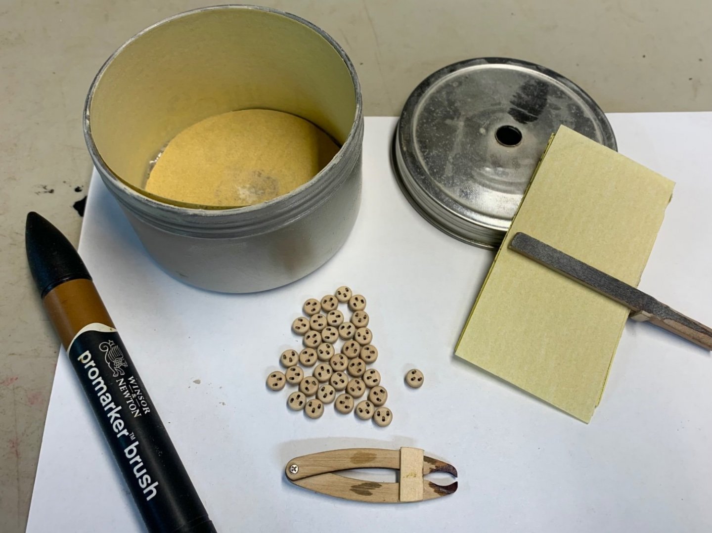
Oh and dont forget to really tumble your deadeyes. I realize many of you prefer deadeyes already made up. But if you like the mini kits it is crucial to tumble them. Do not attempt to sand each by hand. My home made tumbler below with the 6mm deadeyes ready for dying. I tumbled the heck out of them to really round off the edges and get rid of the char. The secret is using the correct sandpaper. In this case 400 grit. Tumbled on the highest speed my drill would run which is 3500 rpm.
- 1,784 replies
-
- winchelsea
- Syren Ship Model Company
-
(and 1 more)
Tagged with:
-
Just an FYI....normally I sell my deadeyes 28 per package. But since the Winnie will need 34 six mm deadeyes, I have adjusted the 6mm packages to now include 35 deadeyes. So now you dont have to spend all that extra money for second package which will mostly go unused. You will now just need to buy one package each of the 6mm and 5mm deadeyes.
- 1,784 replies
-
- winchelsea
- Syren Ship Model Company
-
(and 1 more)
Tagged with:
-
Too funny…but yes. Duplication and not innovation. Very different things. Just remember where you saw it first. Its the story of my life, LOL.
- 1,784 replies
-
- winchelsea
- Syren Ship Model Company
-
(and 1 more)
Tagged with:
-
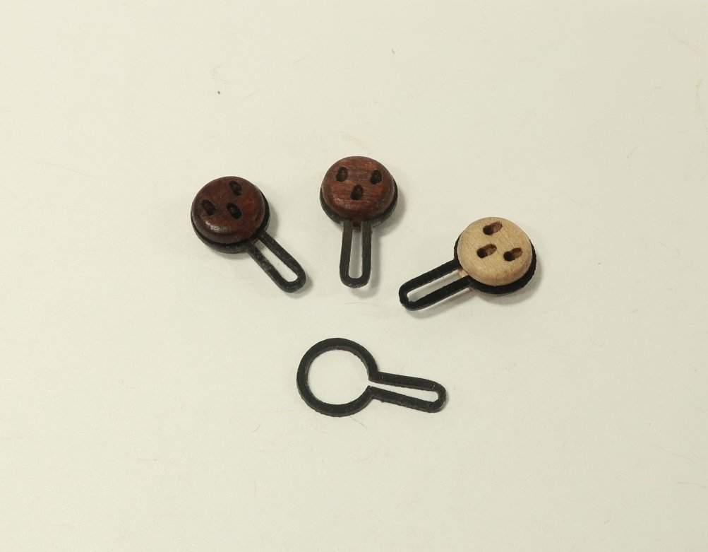
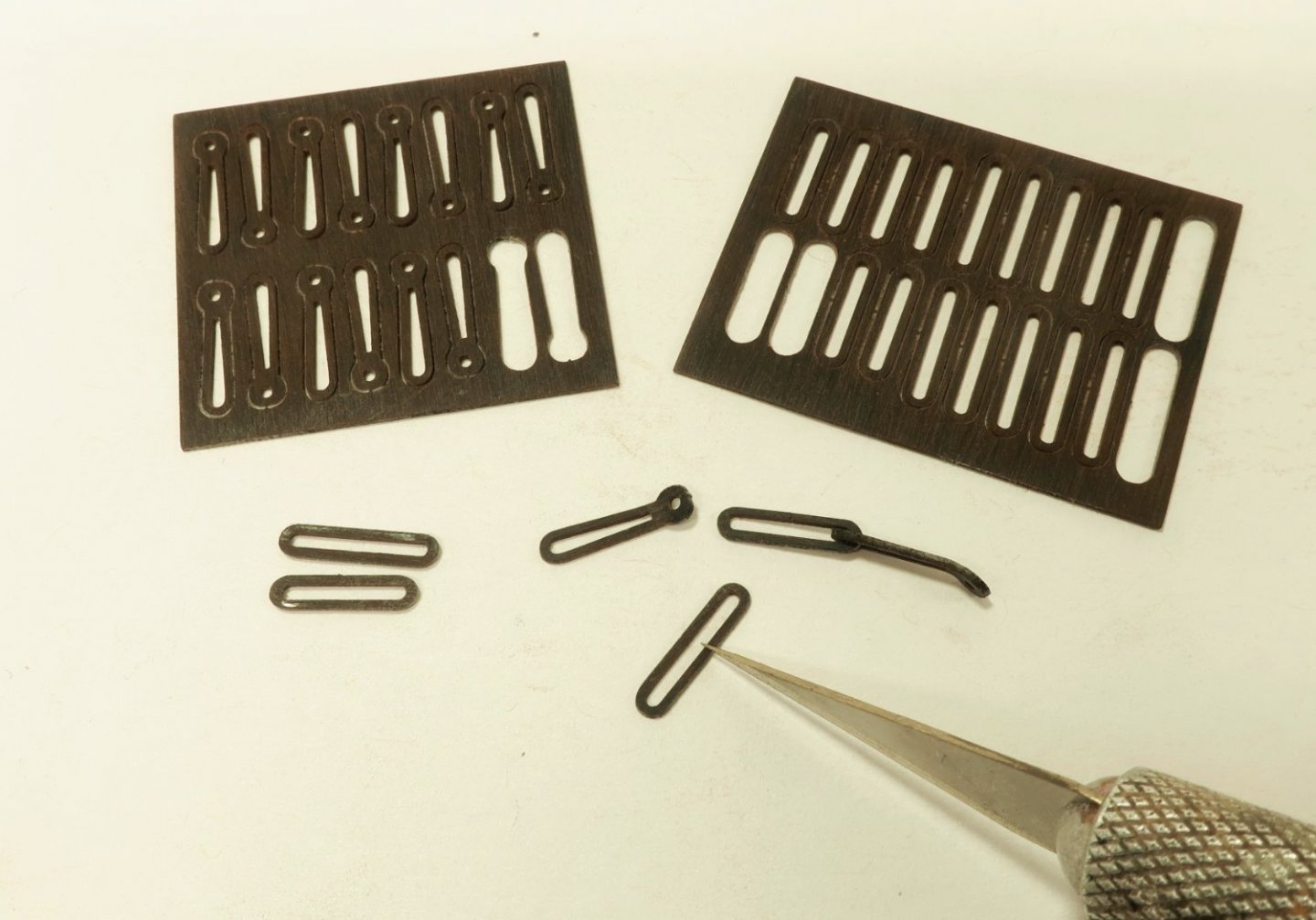
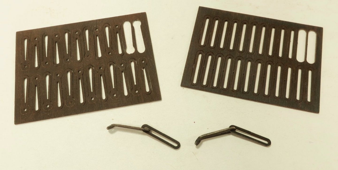
With the straps comlpeted for the channels first it was time for deadeyes and chainplates. The deadeyes are made in the usual way. These are the three layer deadeyes. I started by making all of the 5mm deadeyes first. There are instructions for assembly and tumbling on my website already. I will add however that I tumbled them with 400 grit sandpaper. Dont be afraid to tumble them for a while so they get good and rounded off while removing the laser char. I do this on the highest speed on my hand drill. Then I used the acrylic strops to strop them all after I dyed them brown. See below. The strops can be flexed with your fingers around the deadeyes. You need to get a knack for it but once you do its easy. Should you break any strops its no big deal, there are plenty of extras on the sheet. Yes I did sand the sheet of strops as described earlier and weathered them before placing them on the deadeyes. I show a natural deadeye so you can see both. My wife says I need to try new things....so this is the first time I have ever dyed my deadeyes and gone brown. I like it but yes it was a difficult choice to make. Once stropped, I placed all the 5mm deadeyes along the channels. Just slide them into the slots where they go. There are 5mm deadeyes and 6mm deadeyes. I am starting with the 5mm first. You can see them all along the channel waiting for the chainplates. The chainplates are all different sizes depending on which deadeyes they are used on. I am methodically completing the chainplates based on size. The acrylic chainplates are also cut on individual little sheets by size to make life easier as well. All of the chainplates for the deadeyes on the stools will be done first. They are the smallest links. Take a look at the photo below which shows the two sheets with the smaller parts for the stool chainplates. There is a sheet with the center links and one of the lower link that terminates with an eye on the bottom. This is where you will nail it to the hull with little brass pins. Pins Not included. You can buy them easy enough by the hundred. There are two lengths of the center link. The shortest are for the mizzen stool. But the bottom links are all the same size for all of the stools. Start by sanding and weathering the sheets on both sides again.....this will be done for all of them. Then take the center links and cut one side with a sharp blade as shown. This is how you will get it onto the lower link and onto the deadeye strop. I could have laser cut these but then the kerf of the cut would prevent it from closing entirely. By cutting one side with a blade like this they will close up and you will never ever see the seam. Then take the lower link and bend the bottom slightly. NOT a huge amount. Its about a 45 degree bend. Use a needle nose plier like I showed earlier for the straps. Heat the tip with a candle flame and use it to help bend the bottom eye as shown. If you try and do this cold you may break the lower link. If you use heat you wont break any. And dont worry there are plenty of extras. Then combine the center and lower links so we can add them to the deadeyes on the stools. The seam of the center link is positioned so its the back side of the link when placed on the model. In the photo above you can see all of the chainplates completed for the stools. But you can also see that I completed them for the mizzen channel as well. The plates for the mizzen channel and the the other channels where 5mm deadeyes are being used are slightly longer than those used on the stools. But the process is exactly the same. Here is a photo of the laser cut chainplates for the deadeyes on the channels. So you know what to look for. You can see how the seam on the split center link is nearly invisible after slipping it onto the lower link. If you look at the photo again showing the chainplates completed on the hull for these 5mm deadeyes you will notice that only the ones on the mizzen channel are completed and nailed with little brass pins. The two on the main channel and the one on the fore channel are just dangling. I have not nailed them in place permanently yet. I am waiting until after I make the 6mm deadeyes and all of them are hanging on the main and fore channels. I like to wait so I can better establish the correct angles for the chainplates. You can take these directly from the plans. One last note....many of you may feel that these links are too delicate. You might think that they would never hold if you decided to rig the model. That is the farthest thing from the truth. You would not believe how strong they are. If you are worried about the seam in the center link...you should be. But alas, should you really want to "solder" the seam closed you absolutely could. But you must use a special glue for acrylic. Its the same stuff they use when gluing the display cases together with acrylic sheets. Incredibly strong stuff and thin like water. Just take a drop on a toothpick and simply touch the seam if you can see it on the center link. And thats it. It will wick into the seam and you are done. Dont touch it. It will take some time but it literally melts a small amount of the plastic and once it sets it is once again an unbroken link. It will be extra strong now. But not too much of the glue. Because we are not rigging the model anyway that is just not needed. But go ahead and give the deadeyes a good tug on the channels and you will see how sturdy and solid they remain in the slots with little movement. Its a beautiful thing. Next up are the 6mm deadeyes....this went very quickly without having to bend the wire to make these....it took just a couple of hours to do the 5mm deadeyes once they were dyed. So hopefully the next update will be soon and these will all be done.
- 1,784 replies
-
- winchelsea
- Syren Ship Model Company
-
(and 1 more)
Tagged with:
-
Its too expensive and too time consuming to laser cut this material for samples. Its up to you after reviewing more folks that use them. Remember that Cheerful had just 8 deadeyes. They were also secured with just straps. The Winnie is a whole different ballgame. with close to 60 deadeyes all needing varying sized straps and chainplates, it will take a while. But its all fun in the end.
- 1,784 replies
-
- winchelsea
- Syren Ship Model Company
-
(and 1 more)
Tagged with:
-
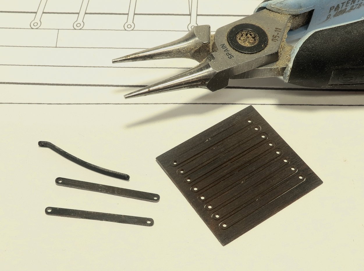
You can see the one deadeye and chainplates in the photos from my previous post. Yes originally I was using natural or bright deadeyes. But I may switch to dyed brown deadeyes. I havent decided yet. See below. But that isnt why I am posting this new image. The older image shows the chainplates made the old-fashioned way. Same is true with the straps you see. I used 22 gauge black wire and carefully bent them around various jigs to form the chain plates. The deadeye strop was also done that way. It is of course very time consuming and a bit frustration. But it looks great. But it would have taken me weeks to make all of the metal parts by hand like that. Many of you may well dread the thought of it. It is the cheapest option though!!! What I wanted to show you is a new product that I have finally taken the time to try out. Its not photo-etch which you are familiar with. I hate photoetched chainplates. The material is too thin and its not fun to blacken all of those parts. It looks very kit-like to me. Anyway, this is a new acrylic black sheet material. It is just .020 in thickness. It laser cuts beautifully. I was very skeptical and thought it would never work. But I am astounded at just how well it worked. The channel straps below as well as the deadeye strop and chainplates in the photo are laser cut from this acrylic sheet. I think you guys will like this. The downside is that its very expensive. Probably on par with the cost of photoetch...but it looks so much better for this application. Would you believe that the deadeye chainplate below is acrylic? Here is another photo of the straps before adding them to the model. Here is how I worked the material. First I sanded both sides of the sheet with 400 or even 600 grit sandpaper. I recommend you do the same should you opt to buy the chainplate set. Then I applied some brown weathering powder like I did for the metal work. This really did the trick. Normally the acrylic has a satin side and a glossy acrylic side. Sanding both sides makes them even and also helps the powders to work. Also note in the same photo below that the one strap has been bent in a nice curve. This is what you want to do with each strap. But one end has a more severe bend in it. This end sits against the hull and has a small brass nail (you know the nails) to secure it to the hull. This bend was problematic. The acrylic was a bit brittle when bent cold. It had a tendency to snap. So more experimentation led me to discover that if you hold a needle nose pliers over a candle flame first, (Not too hot....but hot enough) then grasp the thin strap and slowly bend it, it will not break. You can bend it pretty good in fact. Just keep a small candle next to you as you bend these. When the pliers get cold just hold the tip over the flame for a few seconds until hot. The chainplates were bent like this as well. More on that later. The deadeye strop is a solid piece by the way. This acrylic product is wonderful in that you can flex it over and into the deadeye strop slot. This makes life easier. The chainplates are then a snap to add after inserting the deadeye along the channel. But I will discuss a few more details on the chainplates as well soon. But for now I wanted to show you this neat and wonderful new product. I will try and find other uses for it as well. I think that one chainplate assemble with brown deadeye looks wonderful. What do you guys think. Like I said this set of chainplate materials will be available separately from chapter 11 because it is very expensive. Many of you may prefer the old fashioned way. You will still be able to make your chainplates from 22 gauge wire if you want to and all of your straps from 1/16" 1/64 brass strips. You will now have a choice. Also a photo showing more straps on the main channel...and three color choices for deadeyes. The darkest brown is two coats of dye from a Windsor and Newton Promarker. The lighter brown is one coat....Burnt Sienna. The natural is next to it for comparison. Any favorites?
- 1,784 replies
-
- winchelsea
- Syren Ship Model Company
-
(and 1 more)
Tagged with:
-
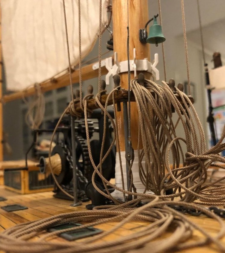
Just an FYI, Syren is fully stocked with rope and still sells it. I will be doing so for the long term now that I have found much needed help to keep Syren Ultra Scale Rope stocked regularly. Here is a look at it on a model with the rigging process well underway.
-
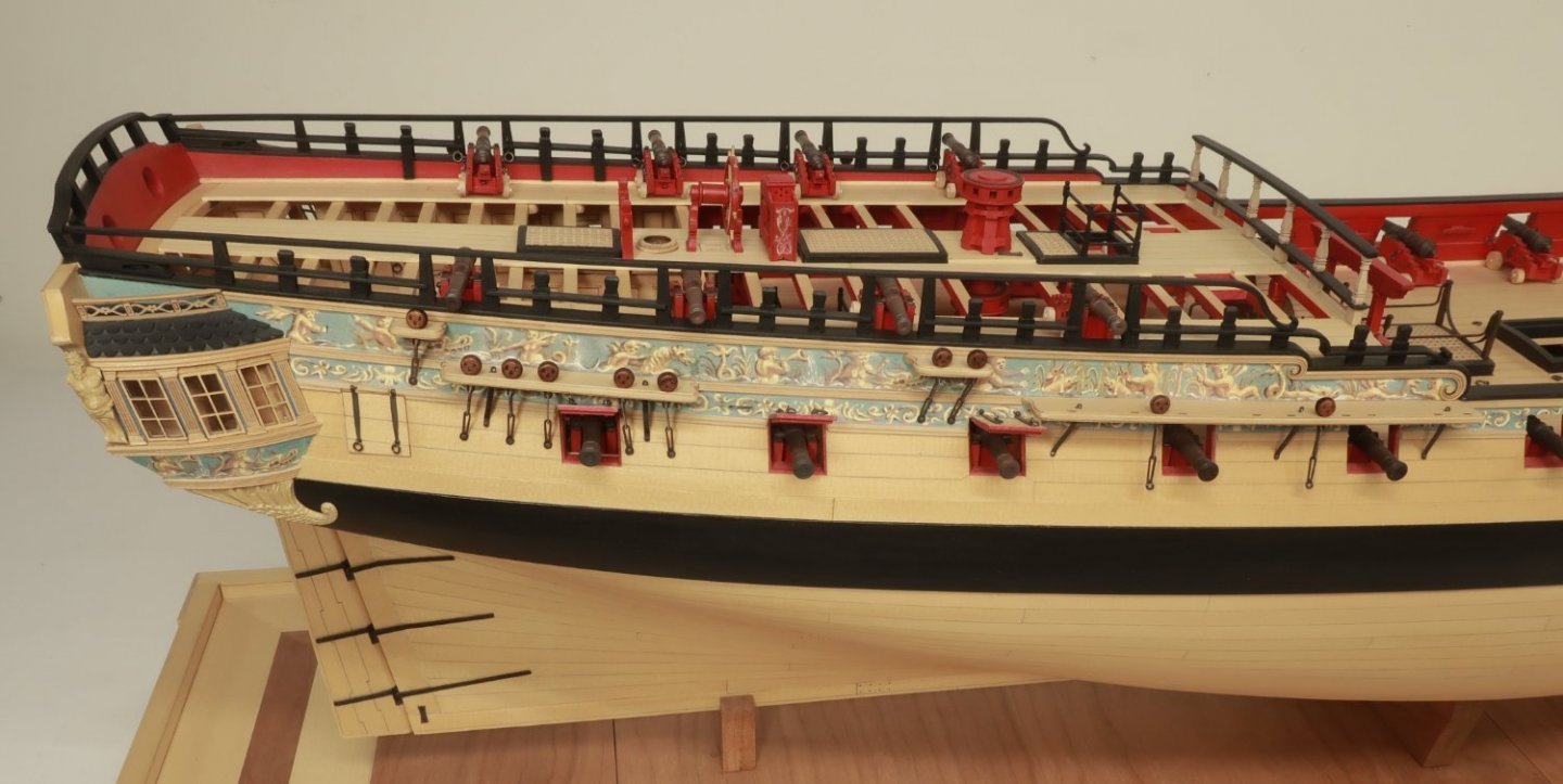
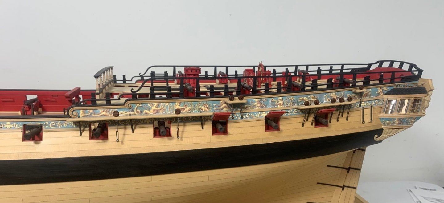
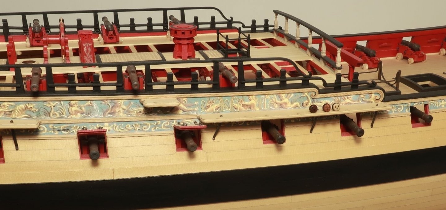
Thanks Ben I am looking forward to seeing some progress on yours too. You are finally getting to the fun parts. Anyway... Just a few quick photos. I finished making and installing all the channels and the stools. I also had time to play around with making the brackets/straps which you can see on the channels. Most kits will just glue some eyebolts into the top of the channel. They are actually brackets. The top protruding through the channel has an eye on the end which the rigging hooks to. But their are some ways to simplify these. I will detail them soon. These straps are just made from 1/16" wide x 1/64" thick brass strips. They are simplified a great deal compared to those used on the actual contemporary model. I have just made two so far and will take many more photos of the step by step. In addition we will be using two sizes of deadeyes. 6mm and 5mm deadeyes. I have made a few of them and tested my process on the mizzen stool. That uses a 5mm deadeye. I made up some chainplates quickly for it just to see how one would look. The chainplate links are made from 22 gauge black wire. These deadeyes are my three layer min-kits. I like them much more than any others I have seen available. But everyone can buy them based on your preferences. I know a lot of you prefer not to assemble the deadeyes in favor of those that are ready made. I am biased however and just like these better.
- 1,784 replies
-
- winchelsea
- Syren Ship Model Company
-
(and 1 more)
Tagged with:
-
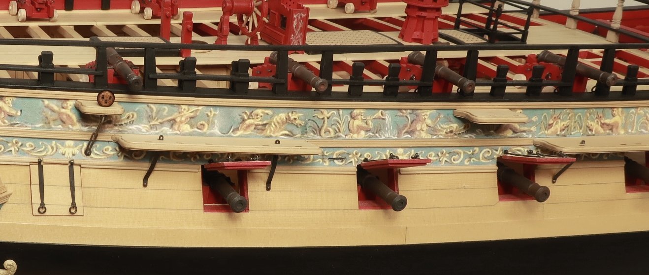
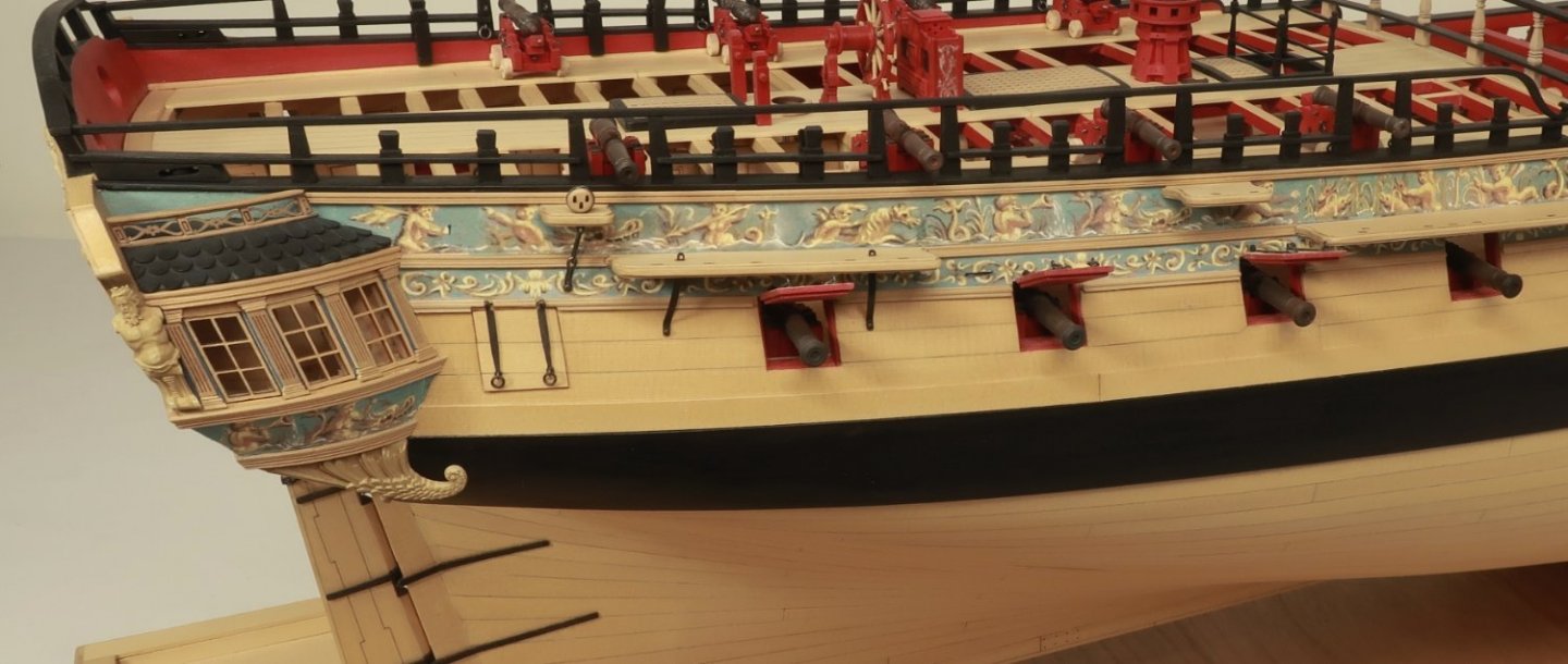
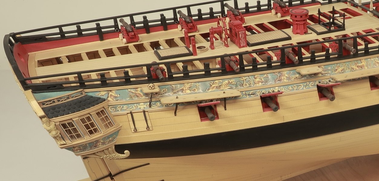
Thank you guys. One other note worth mentioning... Someone had asked if I was going to add the channel knees. There would have been five along the top of the main channel and four along the fore channel etc. The contemporary model doesnt show these but I was originally going to add them. I have changed my mind however. There is a very legit reason for this. The beautiful painted friezes. The figures and friezes were taken directly from the contemporary model. Since there werent any knees, no space was allocated for them. If we were to add them, the knees would fall exactly where some of the best and most detailed parts of the frieze are located. For example, some on the main channel would completely cover the figures and their faces, or the tails etc. Now you could paint them on top of the knees but even if done perfectly it would look very odd. Therefore the knees will be omitted and follow the same look as the contemporary model. At least on my model but if you choose to add them that would be your choice. Also note how the top of the channels are painted black with only the profile edges left bright. I have decided to leave the channels entirely natural which I prefer after looking at so many other contemporary models. Dealers choice with that.
- 1,784 replies
-
- winchelsea
- Syren Ship Model Company
-
(and 1 more)
Tagged with:
-
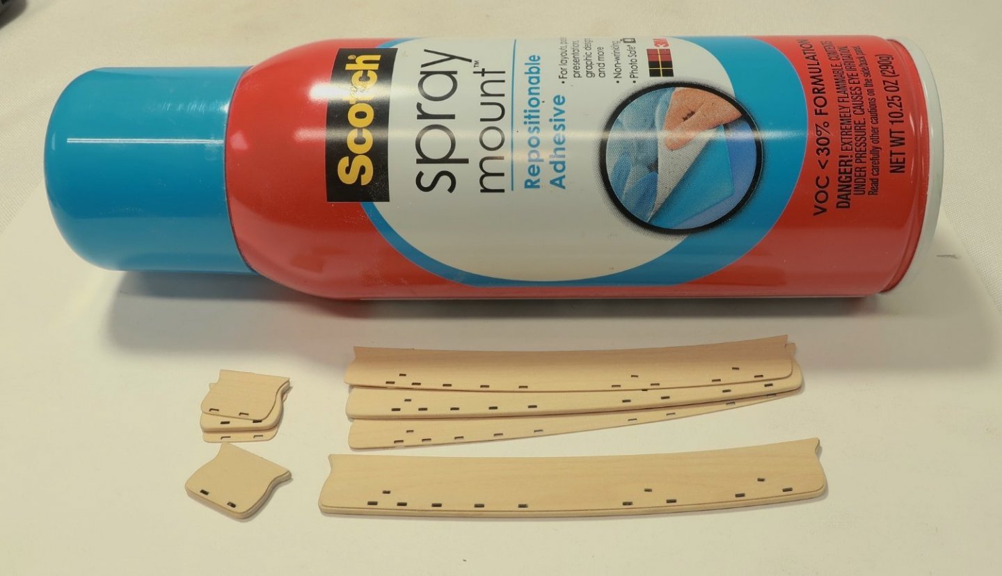
Thanks Rusty. The secret is the spray mount. I tried with titebond and it was a dismal failure. I know it sucks to have to buy yet another product for just a few parts, but seriously in this case I am urging you guys to do so at this step. it makes a huge difference.
- 1,784 replies
-
- winchelsea
- Syren Ship Model Company
-
(and 1 more)
Tagged with:
-
For placement of the channels It depends….check the plans. The stools are under the molding but the others have the molding chiseled away first. Just to let you know I am also redoing the stools. Before anyone catches that. The ones shown are too deep and should be narrower than the longer channels. That will be done today.
- 1,784 replies
-
- winchelsea
- Syren Ship Model Company
-
(and 1 more)
Tagged with:
-
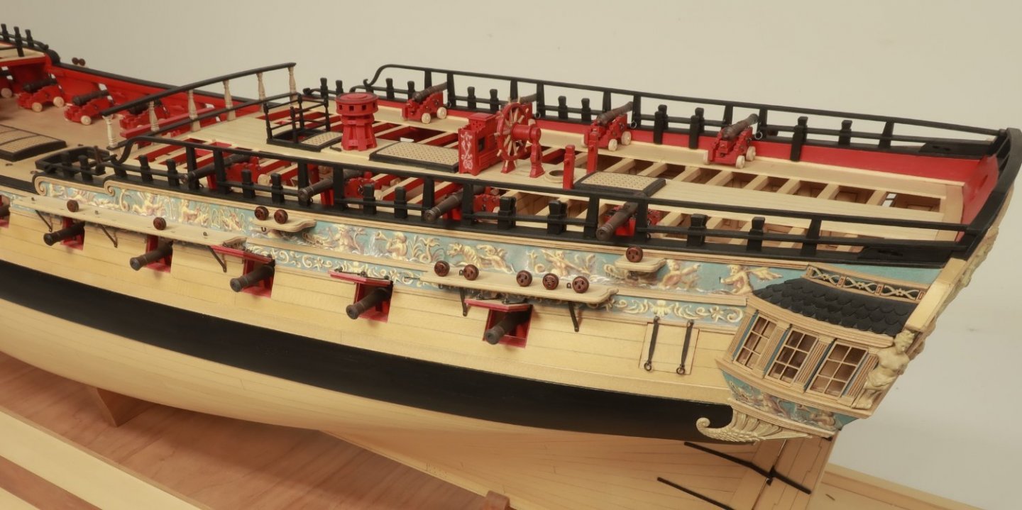
Just a quick update...Chapter 11 has finally begun. It will detail the outboard stuff. The channels, fenders and entry steps, deadeyes and chainplates etc. First up are the channels. Most kits dont detail these very well in my opinion. Plain edges etc. I wanted to try and emulate the profile seen on most contemporary models. I decided on the multiple layers approach. But this meant using an incredibly thin top and bottom layer to pull off the look I wanted. Luckily Joe at Modeler's Sawmill was able to mill paper thin wood sheets for me. The top and bottom layers are so thin that they will curl and possibly lift up if you use traditional yellow glue. It is just too wet. So a really good solution which worked excellent was to use spray mount. I sprayed only one side of the thin layers with glue and it didnt curl at all. No need to spray the thicker center layer. I absolutely think that you should do it this way as well. Trust me when I tell you that if you dont, you will be emailing me for replacement parts. There was no curling or lifting of the edges at all. Just align the holes in the layers after sanding the laser char first. Also soften the hard edges of the center layer before gluing up the sandwich. Not a drastic rounding but knock-off the hard edges and soften them. It does a nice job giving the edge profile I was looking for. Now you can absolutely paint these but contemporary examples are all over the map. The Winnie cont model has them painted black except for the outside edge profile. Others leave them natural. I decided to follow the look of the Amazon model. They will be left natural. Next up will be the knees or standards along the top of the channels once I finish up the other channels first. These again may or may not be painted. I recommend that you examine many contemporary models and select a look that you prefer.
- 1,784 replies
-
- winchelsea
- Syren Ship Model Company
-
(and 1 more)
Tagged with:
-
Looking sweet!!!! Now its time for the long slog through the bottom planking. Take you time.
- 840 replies
-
- winchelsea
- Syren Ship Model Company
-
(and 1 more)
Tagged with:
-

HM Cutter Cheerful 1806 by JpR62 - 1:48 scale
Chuck replied to JpR62's topic in - Build logs for subjects built 1801 - 1850
Looking great....love the wood choices.
About us
Modelshipworld - Advancing Ship Modeling through Research
SSL Secured
Your security is important for us so this Website is SSL-Secured
NRG Mailing Address
Nautical Research Guild
237 South Lincoln Street
Westmont IL, 60559-1917
Model Ship World ® and the MSW logo are Registered Trademarks, and belong to the Nautical Research Guild (United States Patent and Trademark Office: No. 6,929,264 & No. 6,929,274, registered Dec. 20, 2022)
Helpful Links
About the NRG
If you enjoy building ship models that are historically accurate as well as beautiful, then The Nautical Research Guild (NRG) is just right for you.
The Guild is a non-profit educational organization whose mission is to “Advance Ship Modeling Through Research”. We provide support to our members in their efforts to raise the quality of their model ships.
The Nautical Research Guild has published our world-renowned quarterly magazine, The Nautical Research Journal, since 1955. The pages of the Journal are full of articles by accomplished ship modelers who show you how they create those exquisite details on their models, and by maritime historians who show you the correct details to build. The Journal is available in both print and digital editions. Go to the NRG web site (www.thenrg.org) to download a complimentary digital copy of the Journal. The NRG also publishes plan sets, books and compilations of back issues of the Journal and the former Ships in Scale and Model Ship Builder magazines.

