Chuck
-
Posts
9,703 -
Joined
-
Last visited
Content Type
Profiles
Forums
Gallery
Events
Everything posted by Chuck
-
 That is looking beautiful. Nice work. You are making some great progress.
 -
It just sits in there. Its really quite sturdy. No wiggle at all. No reason to permanently fix it now as I do remove it from the finished base to work on it. I place it in the work base when I work on her. I dont want to damage the fancy finished base.
- 1,784 replies
-
- 7
-

-
- winchelsea
- Syren Ship Model Company
- (and 1 more)
-
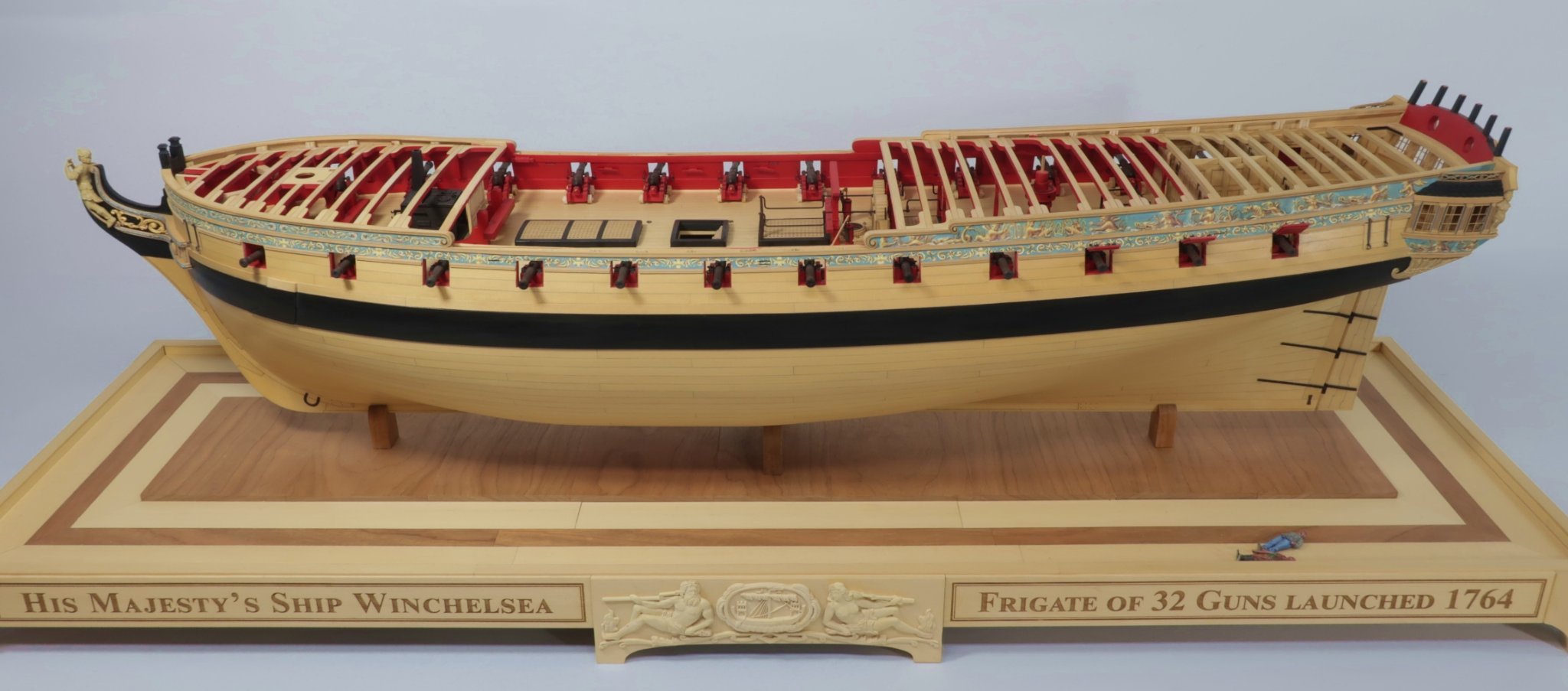
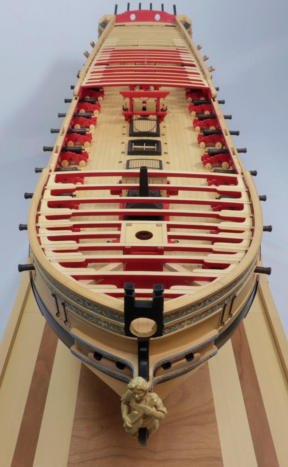
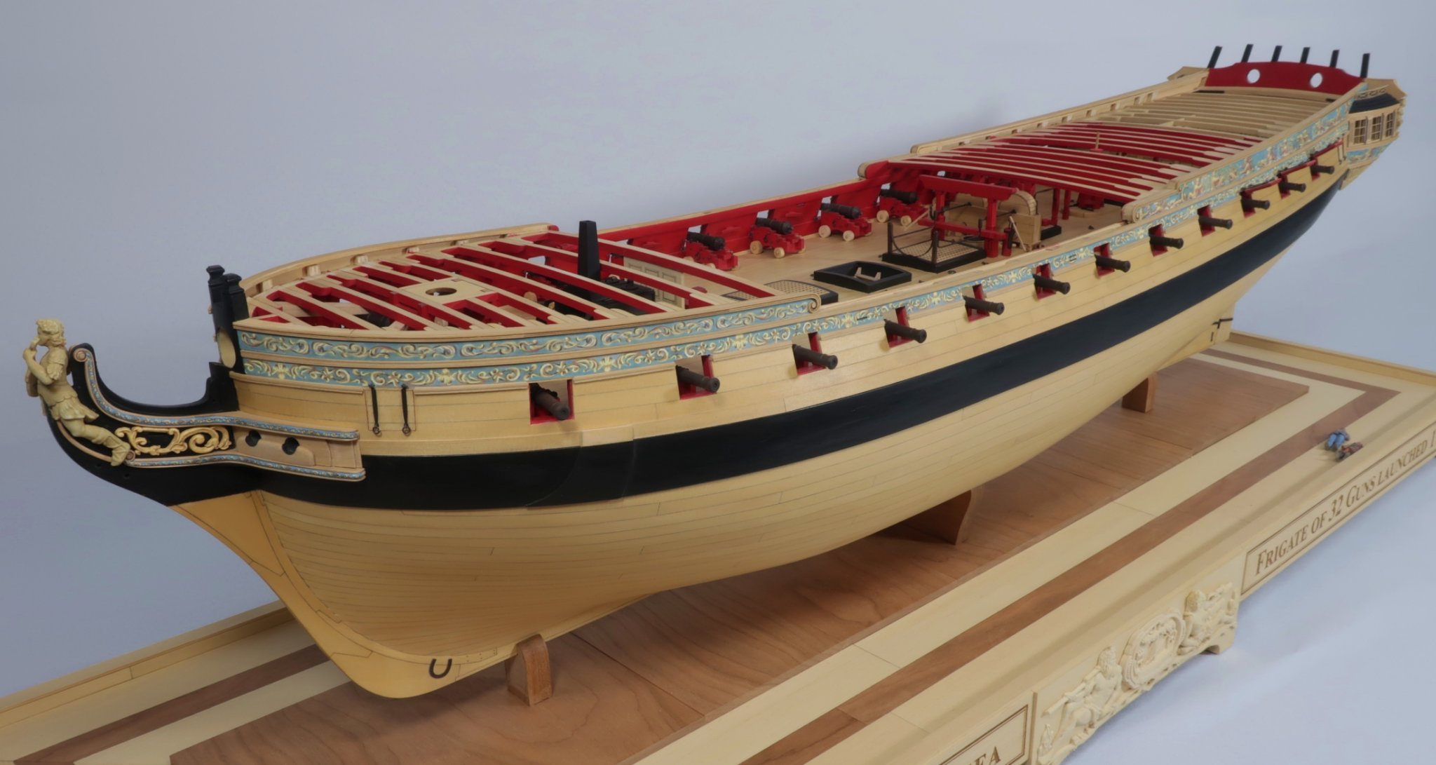
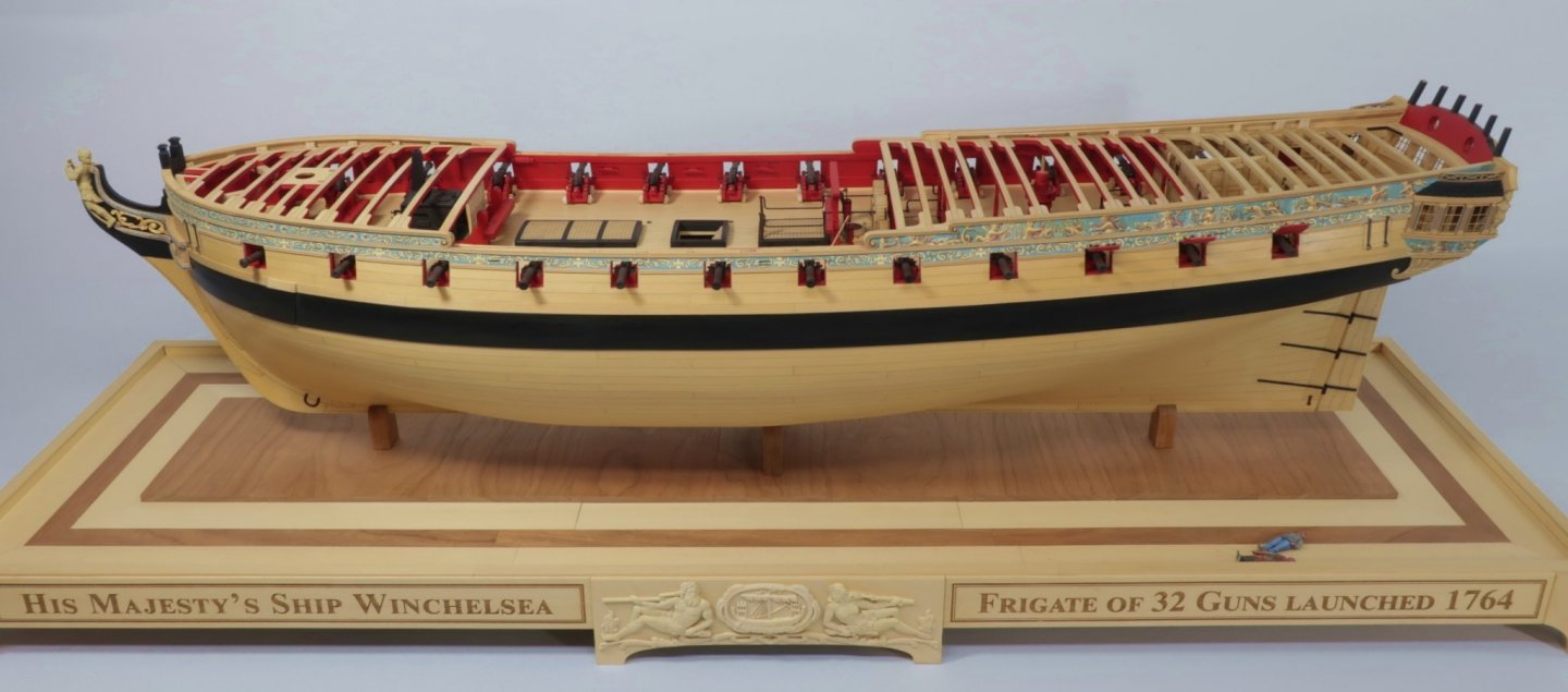
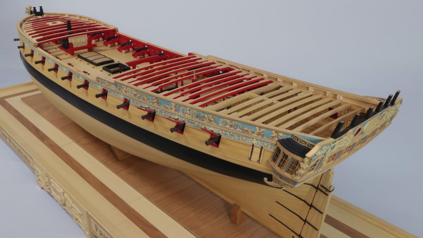
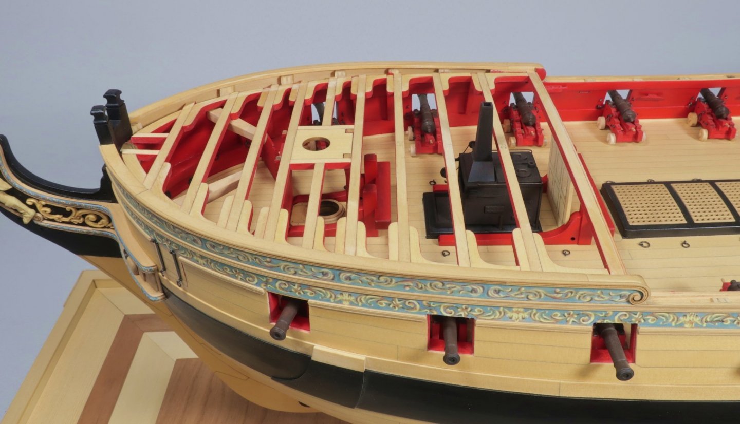
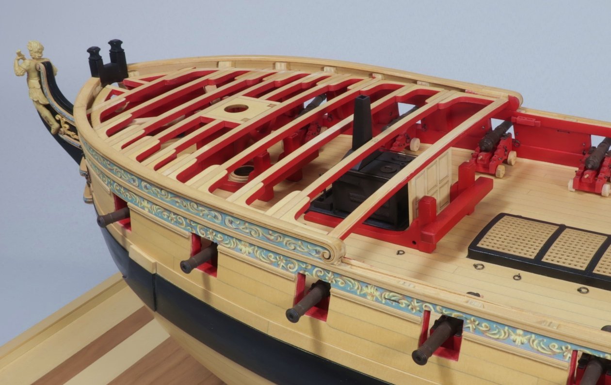
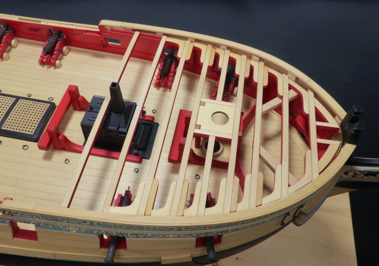
I realize I havent posted an update in a while but I am actually pretty far along. Just been swamped over the last few weeks. In fact, the store is now closed until this Sunday because this is the toughest week so far. Leaving for the Philly "ShipModelCon" on Thursday for some some rest and will resume normal daily function next week. Having said that...the Winnie is quite far along. Chapter 8 s almost finished. The only thing that remains to be done are the carlings and ledges for the deck framing. I may actually do that today and relax while working on the model. I have many many construction photos for the monograph chapter but here are some pics of how she looks today minus those carlings and ledges. Its really coming together now. Notice how the cat tails under the deck framing have inserted. The catheads will be added in two pieces to make it a bit easier. The riding bitts are painted red but you could leave them natural or paint them black as well. I will post more pics upon my return from Battle Ship New Jersey....where ModelCon will be held. I will be displaying the Winnie along with several other models I have completed. I hear there will be over 100 models displayed and the weather looks great for Saturday. Maybe I will see you there.


- 1,784 replies
-
- 32
-
-

-
- winchelsea
- Syren Ship Model Company
- (and 1 more)
-
NAIAD 1797 by Bitao - 1:60
Chuck replied to Bitao's topic in - Build logs for subjects built 1751 - 1800
Beautiful work....clean and crisp and your excellent craftsmanship is on full display. Chuck -
Glenn,, Nope, i may provide some sort of plan for a base but each person will have to make their own. This will be a great opportunity for folks to design and create something that sets the whole display apart from others.
- 1,784 replies
-
- 9
-
-
- winchelsea
- Syren Ship Model Company
- (and 1 more)
-
How to stain or dye boxwood?
Chuck replied to tkay11's topic in Painting, finishing and weathering products and techniques
I dont see the need but i imagine you could. When I use it on AYC i usually apply WOP first. Like a sanding sealer. Just a light coat. Then I use the Gel Stain. But on boxwood I didnt see the need to do so before or after. -
How to stain or dye boxwood?
Chuck replied to tkay11's topic in Painting, finishing and weathering products and techniques
Exactly like the Winnie castings. I have also used it on some areas of the AYC to more closely match Boxwood. Chuck -
That figure looks great. If ever you print any more let me know. I would love to have one. I am sure many others would as well. Chuck
-
How to stain or dye boxwood?
Chuck replied to tkay11's topic in Painting, finishing and weathering products and techniques
Old masters fruitwood gel stain works great for this. Place a small number of blocks on a paper towel or lint free cloth. Then dip another cloth in the gel stain. Simply rub the blocks with it. Get it well covered. Wait several minutes and move them to a clean cloth and use another clean cloth to buff them before the gel stain dries. Dont apply it too heavy or you will clog the holes, especially in the really tiny blocks. Although they are easy enough to ream later. Repeat again after it dries thoroughly to go darker. -
If you have to break that plank into more segments that will be fine. The overall impression of the longboat will be pretty much the same. Go ahead rather than get stuck. Looking forward to seeing some pics.
-
Nicely done. Cant wait to see the final pics.
-
In all seriousness however, it is my opinion that a far more reliable method for telling how many turns is adequate when working the headstock (turning the individual strands) is the distance the headstock travels plus the feel in the thread after twisting it. For example, with the thread I am using as I write this. I am laying up some tiny rope....012 rope. Three stands. I start with the head stock and tail stock 26 feet apart. When I twist the three strands initially the head stock walks or travels three feet. At that point I feel the tension in the thread. Because I have done this more than a couple of times, I can feel when the appropriate amount of tension is built up in the threads. Then I move to the tailstock and turn the strands together. Same thing really. I gun my driver at 3500 RPMs until the tailstock backs away as the rope lays up. Then it starts returning to the original position. When I reach that point I stop and feel the tension in the rope. If it feels right and the lay of the rope looks right. I know its time to stop and the rope is completed. If after I cut the rope free and it unwinds a bit and the lay looks too loose....easy fix. I just increase the initial revolutions of the headstock on my next 8 minute rope creation. For me the feel of the line is most important after experimenting to find what the correct "walking length" for the head stock is. And the results are so surprisingly consistent once you repeat them. This is completely different when I make a different size of rope with a different size thread. I dont think the math would ever be the same for every size and length. Maybe it is though. I just cant believe that it would be.
-
I dont think you can get that scientific about it. Especially because it wont matter much in the end. This is definitely a case of "over-thinking" it. I am sure the number of actual turns will vary and still produce excellent rope. Its akin to wanting to know how many grains of sand is in the sheet of sandpaper you are using to sand your hull and if it takes the same number of grains at 220 grit vs 120 grit to smooth out the rough spots, but only smaller in size. Its neat trivia, but its not something you need to know to produce a good quality rope. It more important that you can feel when its laid up right.....and see when its laid up right.... Just my two cents after making thousands of miles worth of rope over the years. If you get bogged down with the math its gonna get weird. Just give it a go and see what the end results are. I can say this only because I am literally making rope today and with your question fresh in my mind, I had to chuckle as I was doing so. I make 20-22 foot lengths and the drill and ropewalk turns thousands of time over that minute or two. The Drivers I use are rated at 3500 rpms. Was it 10,020 revolutions or possibly 10,090....It isnt really going to matter. Having Math and Science and engineering kids in the family they laugh at me when I tell them I cant even imagine thinking with that side of the brain. The side of the brain I use just starts to hurt. But maybe the more analytical minds can help you find out. I dont even want to imagine that mathematical equation. It would probably have more letters than numbers...LOL. I started running through the factors in my head. It depends on how tight you tie off your thread on each hook. If its not the same each time then that throws off the math. If you tie off the thread just a centimeter shorter for the next rope....it throws off the equation. Then there is the thickness of thread. How many strands? If you lay up cable with multiple strands and change the direction of the drill? My head hurts. I will go with feel and sight every time. It takes about 8 minutes to lay up a 20ft length. If it doesnt come out right I will toss it and just make another and adjust for humidity and wind direction. An interesting question and take on rope making none the less.
-
No i doubt that at all. And the counts on both ends will vary significantly depending on the type and thickness of the rope. It will also vary depending on how many strands per hook there are and based on the amount of time twisting on each side it always seems as if there are more when you twist the strands together.
-
Indeed that looks pretty good. This was a big hull to plank. Properly planking a hull is a tough skill to learn how to do flawlessly. Its not something that most folks will ever learn to do at an expert level. You have done a very good job with it. That is a planking job you should be very proud of. Chuck
-
She looks wonderful. Yes i deed this is what I would call an advanced kit. But when completed with care as you have done…would look right at home next to the most accomplished scratch built barges and contemporary examples as well. you did a wonderful job putting this kit together.
- 185 replies
-
- 5
-
-
- queen anne barge
- Syren Ship Model Company
- (and 1 more)
-
They will fit fine. You haven't faired the bulkheads yet. The forward edge of that first bulkhead will be greatly reduced with the proper bevel. The port framing will fit much deeper after fairing and you will soon find out it is slightly too long. This is why in the instructions i write that the bulkheads should be faired before installing the port framing. It will make positioning the ports framing more accurate.
-
Nicely executed!!!
-
Really nice progress. She looks fantastic.
- 274 replies
-
- 1
-
-
- Cheerful
- Syren Ship Model Company
- (and 1 more)
-
We cant do anything about that. We also want Google to index and find our site. Its how we grow. Its a normal thing to have all search engines find your site and return it in their search results after someone uses certain search words. It can not be stopped. if any member doesnt want their stuff turning up in a search then they shouldnt post it anywhere on the web. Because it will eventually be found through a search engine. I am not sure how they are monetizing anything though…I cant see any evidence of that. Its not what they do. I dont agree with your statement about that at all. Chuck
-
That looks beautiful Ben. That has a really nice run to the planking.
- 399 replies
-
- 4
-
-
- winchelsea
- Syren Ship Model Company
- (and 1 more)
-
Quarter deck beams and planking templates just in case you guys need them for chapter 7. But they will most likely be used later when we plank the qdeck. Also the templates for the carlings and ledges on the qdeck. qdeckplanks-beams.pdf qdeckplanksframing.pdf qdeckplankingtemp.pdf
-
Really nice. Gonna get it done before joint clubs? looking forward to seeing it in person…maybe Philly modelcom?
- 263 replies
-
- 2
-
-
- Medway Longboat
- Syren Ship Model Company
- (and 1 more)