HOLIDAY DONATION DRIVE - SUPPORT MSW - DO YOUR PART TO KEEP THIS GREAT FORUM GOING! (Only 75 donations so far out of 49,000 members - C'mon guys!)
×


Chuck
-
Posts
9,673 -
Joined
-
Last visited
Content Type
Profiles
Forums
Gallery
Events
Everything posted by Chuck
-
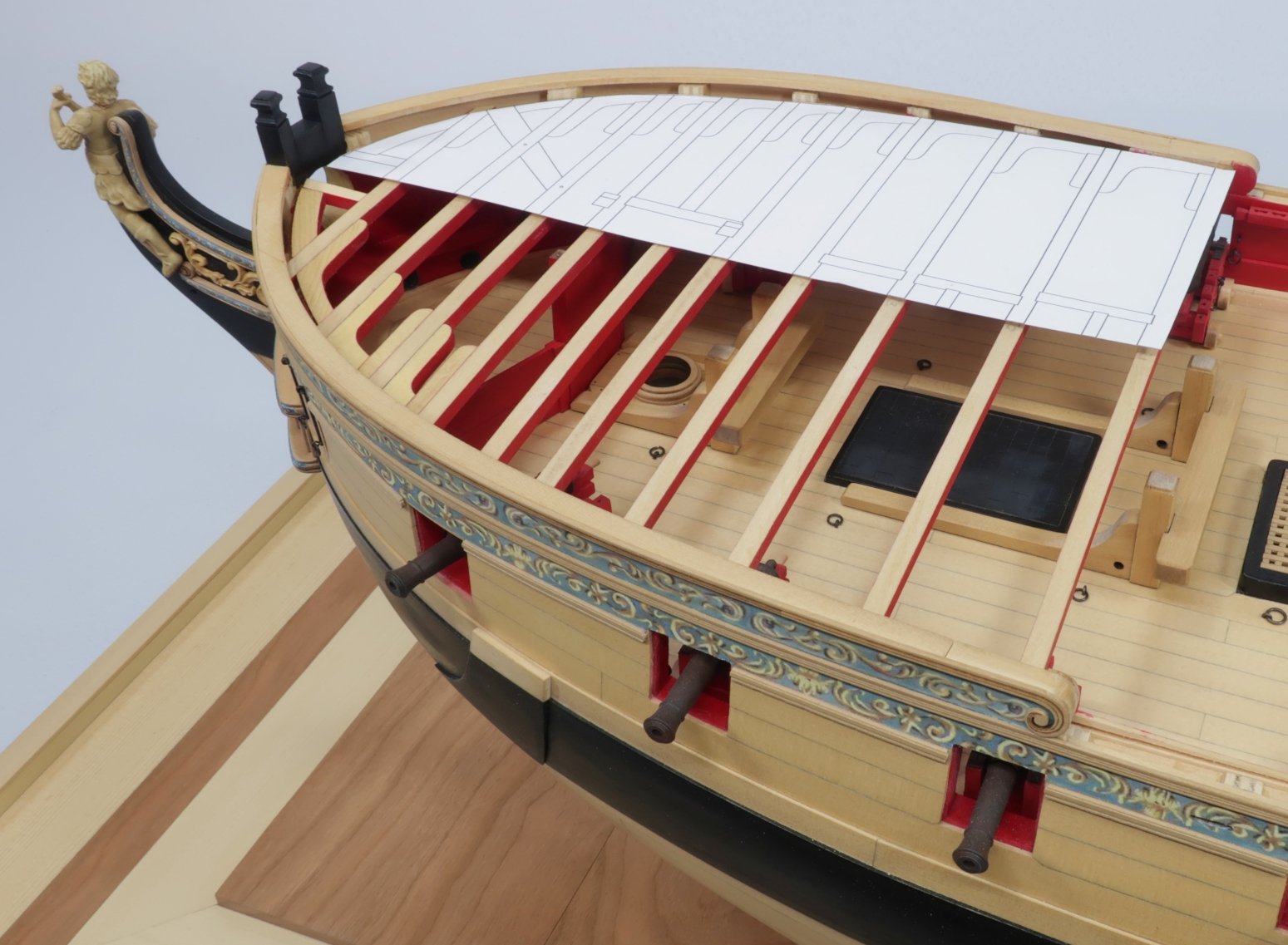
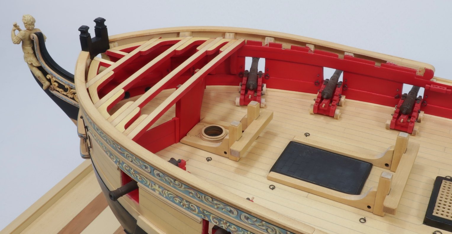
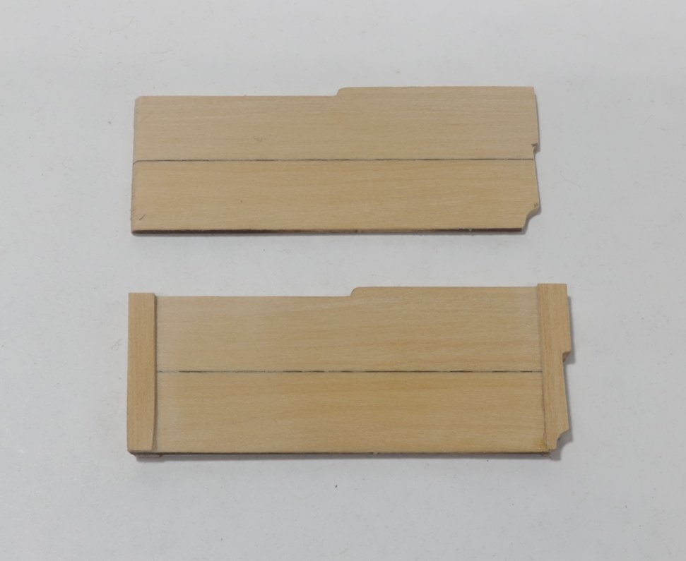
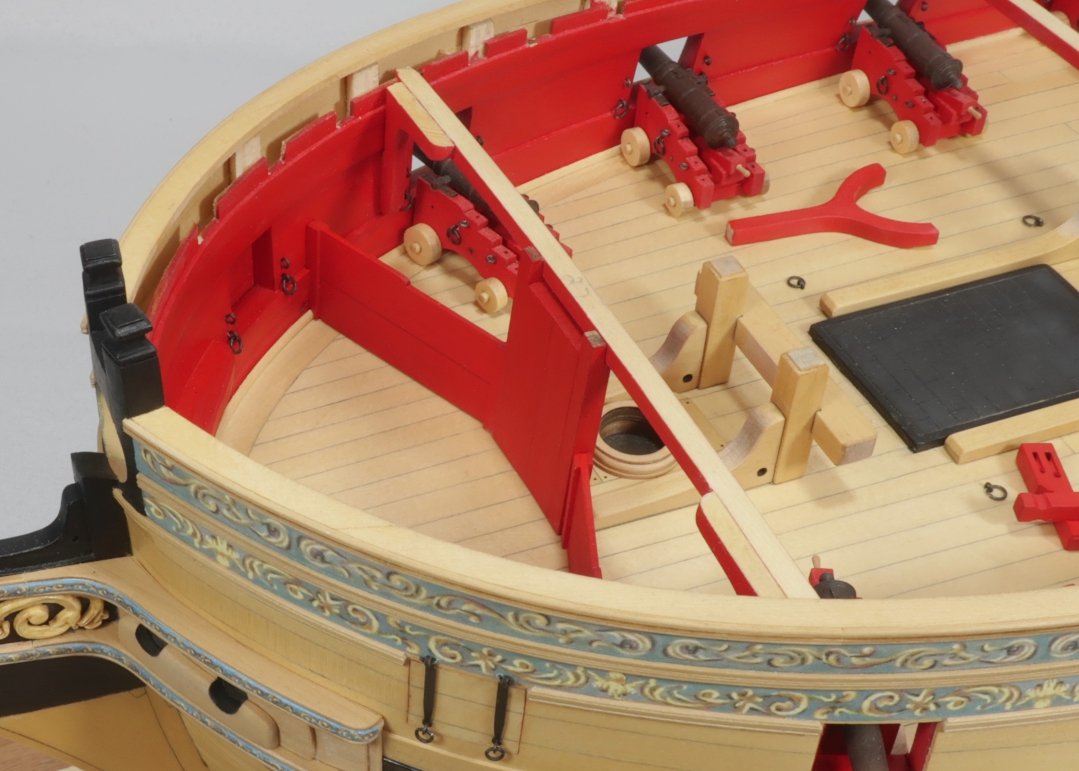
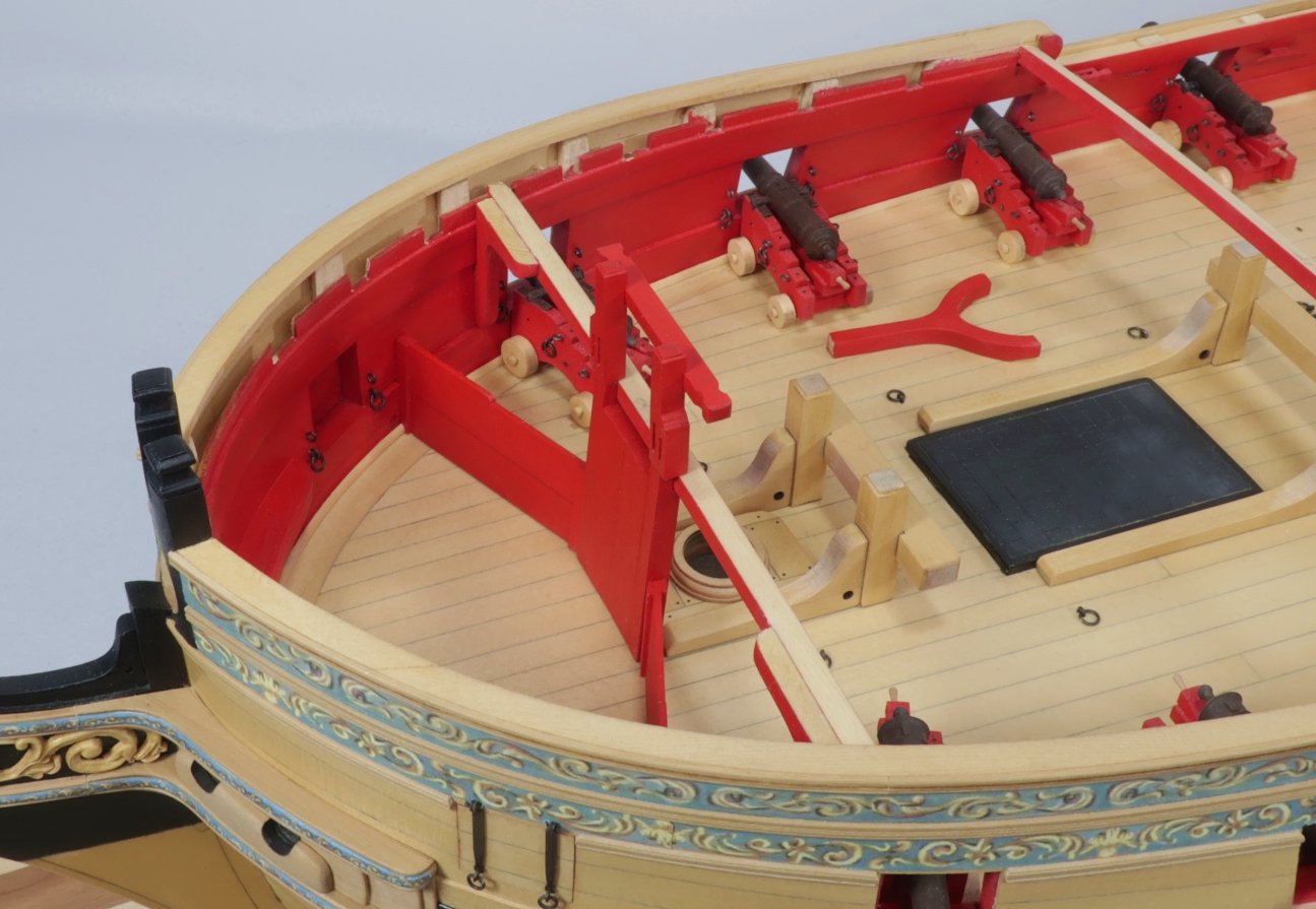
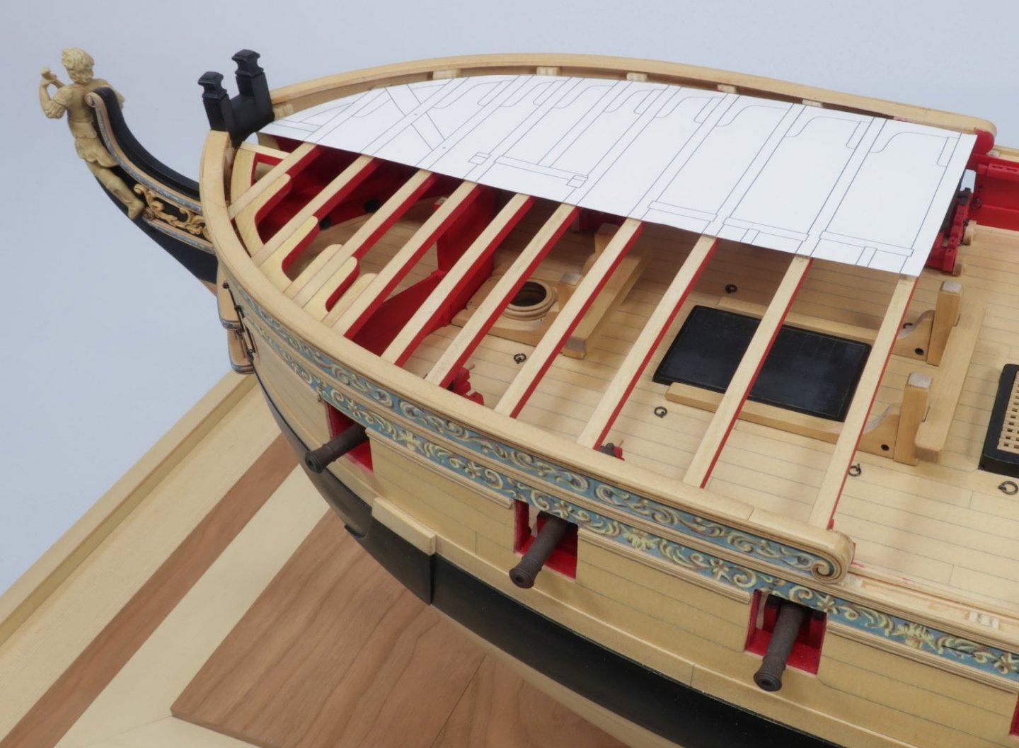
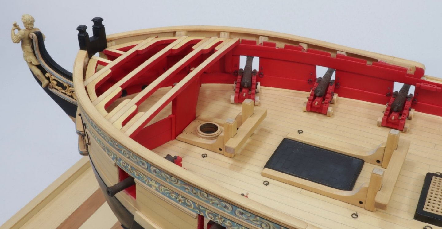
 There are two rails/fore bitts forward and aft of the foremast on the Fcastle. These are interesting fittings in that they extend from the gundeck through and up to the f'castle. So we will start chapter 8 with those. But first a little prep work. I knew when I drafted the plans for Winnie ....specifically the deck clamps...that at the extreme bow I would probably incorrectly space the notches for the deck beams. This turned out to be true. It was difficult for me to design the deck clamps as the rounded the bow so the beams of the f'castle would be properly spaced and positioned. I knew I would be adjusting them before I started making the fittings below the f'castle beams. Turns out that only forward six deck beam notches need to be altered. They need to be moved forward a bit in ever increasing distances as the get closer to the bow. This is very easy to do as you guys only have to widen your notches for those six forward deck beams. So place all the beams temporarily in their current notches and use the supplied template to see how far forward all of those six beams should be moved. The last or forward most beam has to be moved 5/32" forward and requires the most extreme shift to the notch in the deck clamp. Here is a photo of the template in position after all the forward deck beams were moved. You will be referring back to this template often as you work. With that completed lets build the bowsprit step and two rails. But remember that these are all one piece on the actual ship BUT split in half between decks on our model to simplify matters. Even though you will be building the actual rails now for the f'castle they wont be needed until a much later chapter. Its just easier to build them together so they are the same width when completed. This will help the illusion that they are all one piece later on. There is the bowsprit step made from 4 laser cut pieces.....which has a rail above it. There is a "Y" shaped element on the aft side of the foremast which also has a rail above it and was one continuous piece. Or at least they should look that way when done. So build these from the laser cut boxwood pieces. Note the square hole for the aft end of the bowsprit tenon. That was actually a mistake from my original design. The bowsprit angle was changed during construction as noted on the original draft/plans to a steeper angle. This hole was actually below deck and wouldnt be seen so I removed it and made another which you will see. Note how the rails are the same width as the parts below deck and thus its easier to build these together even though we wont be mounting the rails above the deck beams yet. But this is what it will look like and what we are shooting for if it was mounted. We are starting with the fourth deck beam from the stem. The rail is just temporarily in position to show you guys how it should look. But we are basically adding the fourth beam first..... Then positioning the bowsrit step. This has a slight angle as shown on the plans. Then I added the two manger barriers on either side of the bowsprit step. The manger barriers are basically a wooden partition on either side of the bowsprit step. They are laser cut for you. First glue the two flat boards together edgewise to form the barrier. shown on top below. Then take that barrier and position it on the model. Both ends need to be shaped to fit you bulwarks and beveled to fit against the bowsprit step. Each partition will be slightly longer so you can take your time and care to get the correct shapes. Once they fit....add the strops on each end.... 1/8" x 1/64" strips to simulate the slotted fixture these two boards would be slid into. These partitions were always being removed and repositioned to give access to the manger area. As you can see I painted mine red. This is what it looks like all done without the rails above the bowsprit. Note that I also added the hanging knees on each side of the fourth deck beam. It was just easier to add them know. When positioning the manger partitions....CAUTION.... Beware that the position along the bulwarks is important. You will need to keep it clear of where other hanging knees will fall and the scupper should you choose to show them. From this point I added the remaining deck beams....knees and lodging knees moving forward towards the stem. Just use the template and plan as a guide. Its no different then adding the knees for the qdeck. The only difference is that they are on the opposite side of the deck beams this time. Next up I will add the cat tail for the catheads. It will be much easier to add them at this point before I start adding any more fittings and deck beams!!! Any questions.??? Oh yes....I did make the riding bitts but they are just temp positioned. I still have to finish those and paint them. I should have removed them from the pictures before I took them.
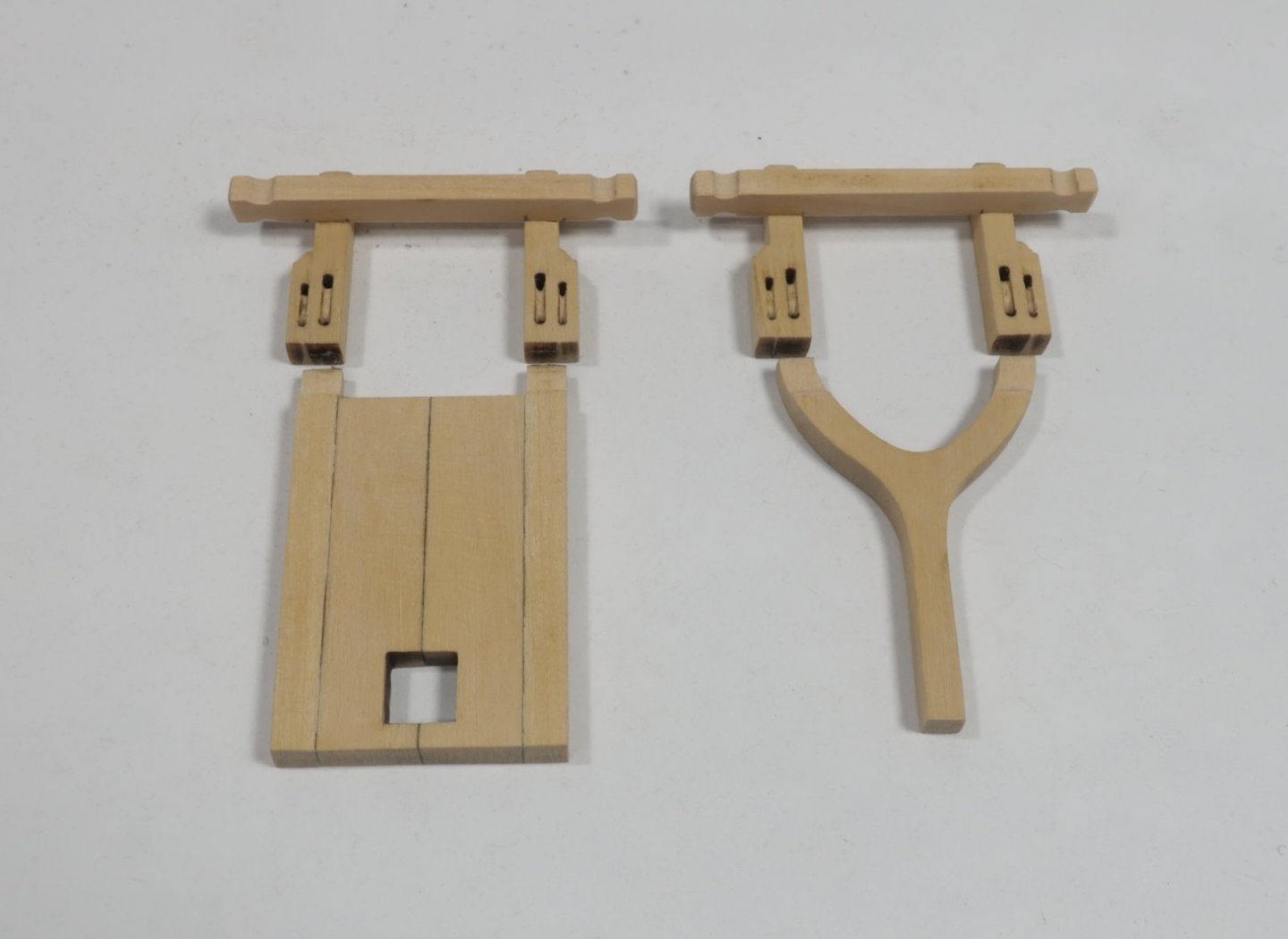
- 1,784 replies
-
- 29
-

-
- winchelsea
- Syren Ship Model Company
- (and 1 more)
-
That is looking pretty darn good. Yes the deck clamp will be all but impossible to see.
-
HMS Snake by BenD - Caldercraft - 1:64
Chuck replied to BenD's topic in - Kit build logs for subjects built from 1751 - 1800
Nice looking rope. Well done! I am sure you will Have many customers. -
5/32" singles..... Rope sizes are more difficult. But I figure .018 for the tackles and .050 to .054 for the breach line. Chuck
- 144 replies
-
- 1
-
-
- winchelsea
- Syren Ship Model Company
- (and 1 more)
-
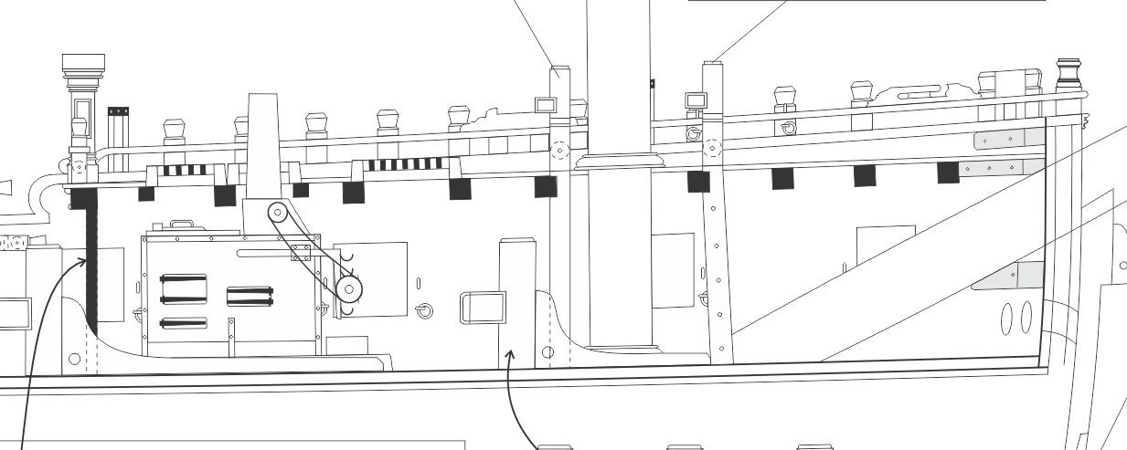
As I am finalizing and cutting Chapter seven parts...here is a sneak peak of what will be chapter 8. I have just started working on these fittings under the fcastle deck beams. There are far fewer items so this chapter should go quicker. The most detailed item to make will be the Stove. The other stuff is quite straight forward.
- 1,784 replies
-
- 29
-
-
- winchelsea
- Syren Ship Model Company
- (and 1 more)
-
I use 15" long at Syren because that is the length of my laser cutter bed. Actually its 16" but I like to use 15" long sheets on the laser. Other than masts it is unlikely you would ever need a piece longer than that. That is if you plank with scale lengths which follows actual practice. Best to keep widths to around 4" to 5" because any sheets you mill that are wider have the tendency to cup. Narrower sheets are more resistant to this. But in the end its up to you. Chuck
-
Nicely done!!
-
Download the entire sail tutorial here. Big thanks to "Tigersteve" for consolidating in a PDF for printing. This is a huge help. Sails for a Cutter Rigged Long Boat.pdf
-
Here's the link to the tutorial...
- 421 replies
-
- 5
-
-
- medway longboat
- Syren Ship Model Company
- (and 1 more)
-
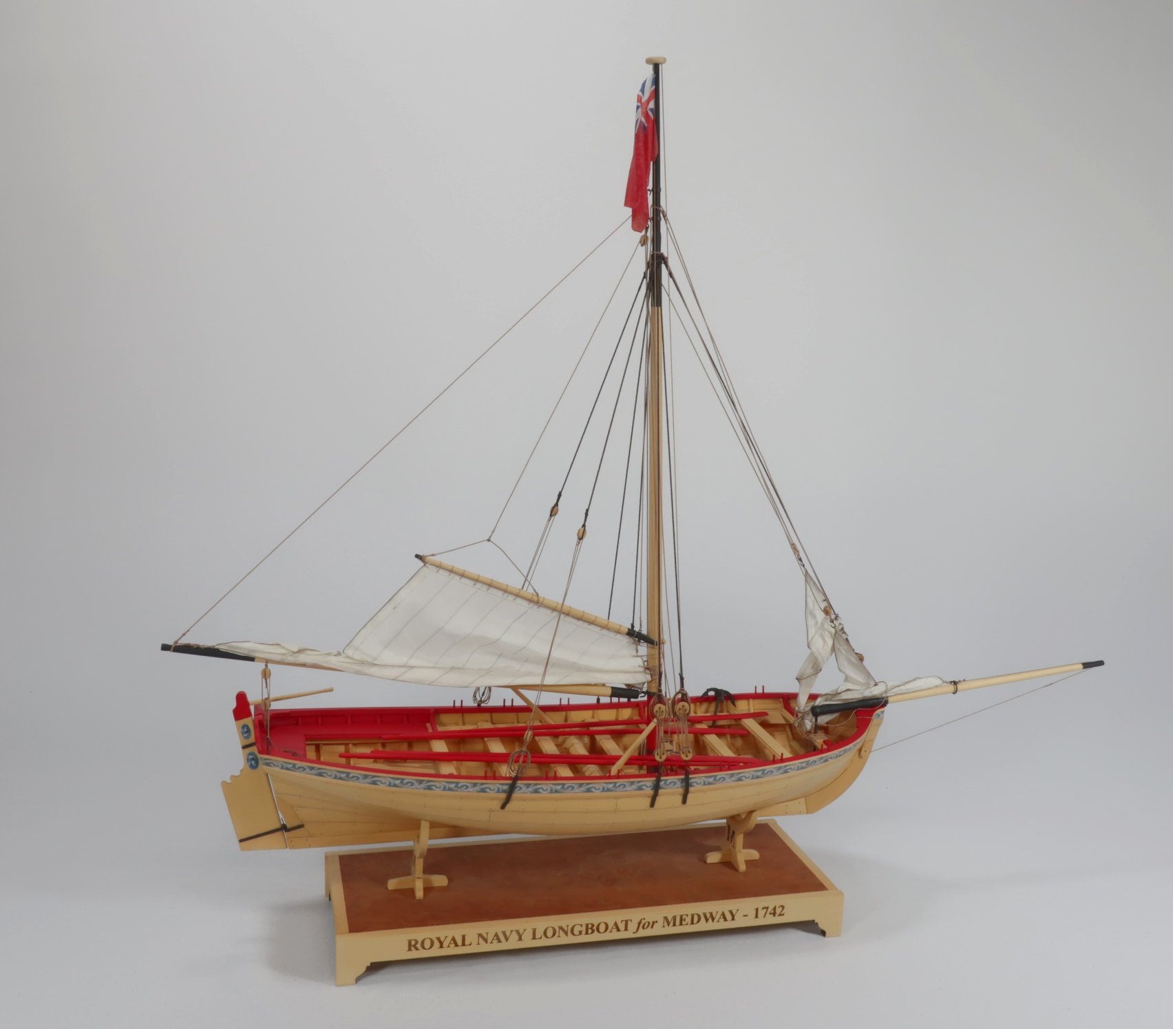
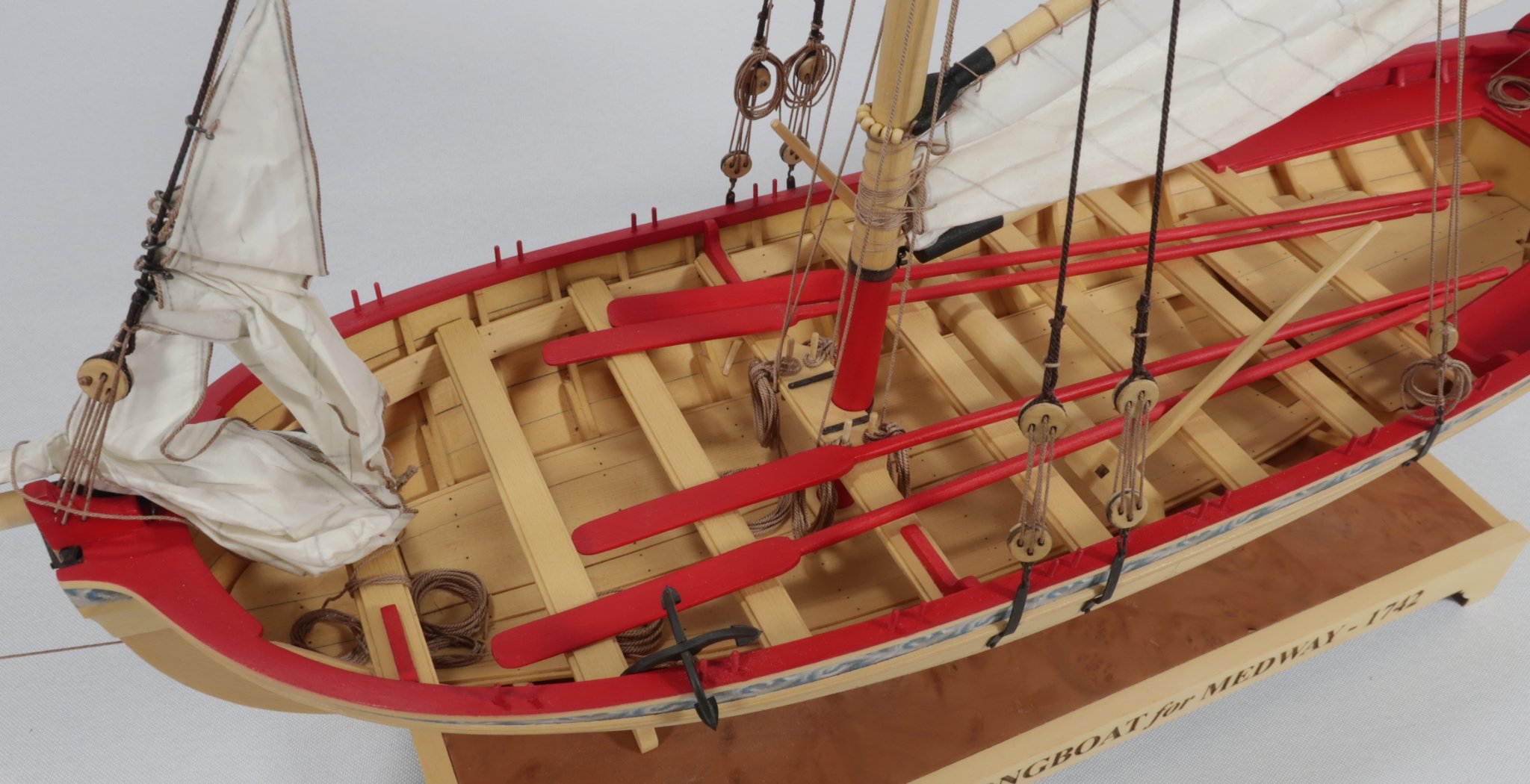
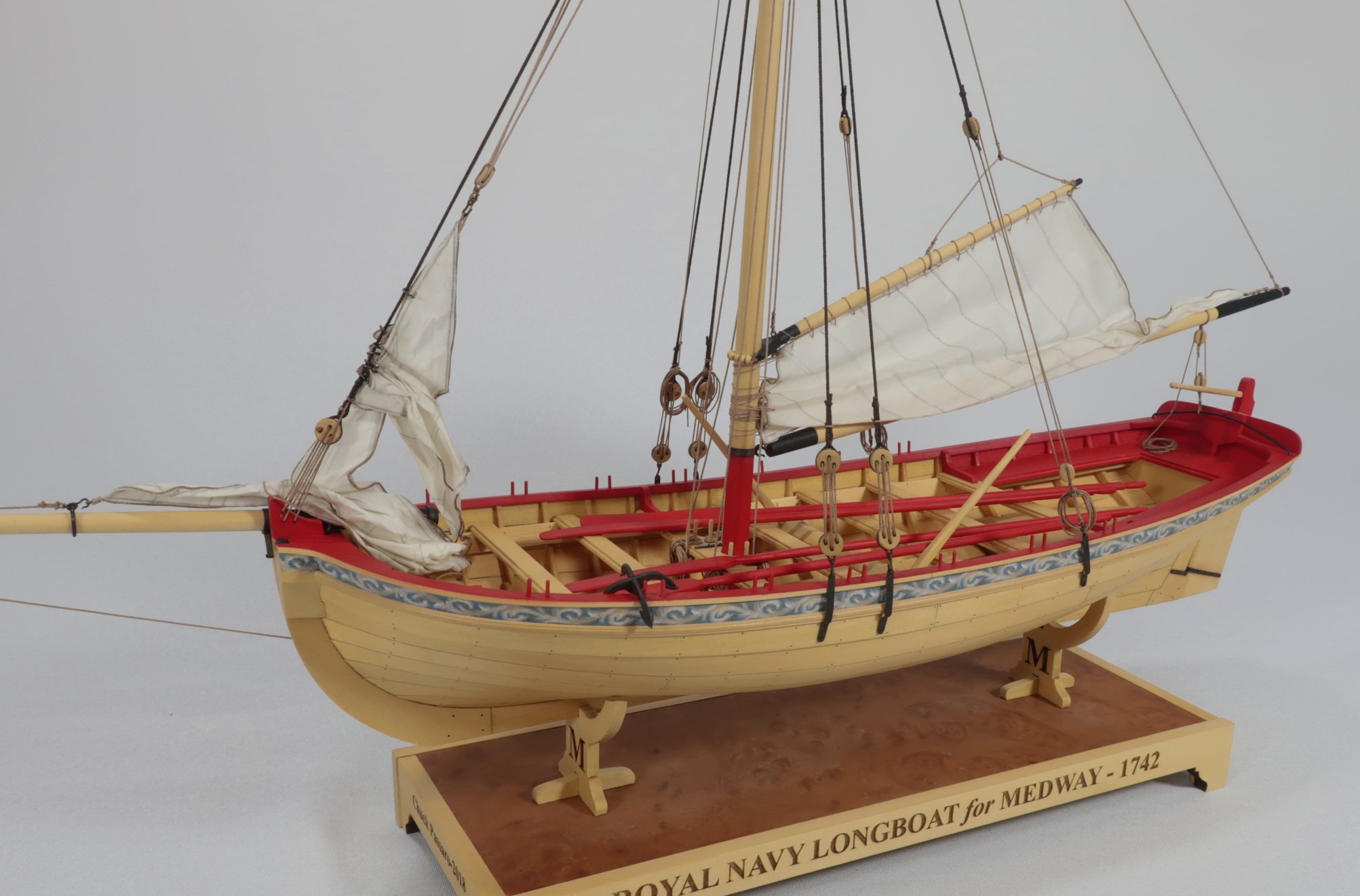
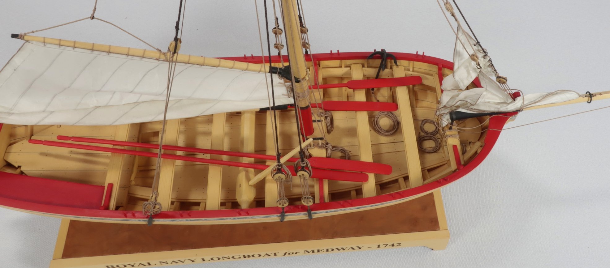
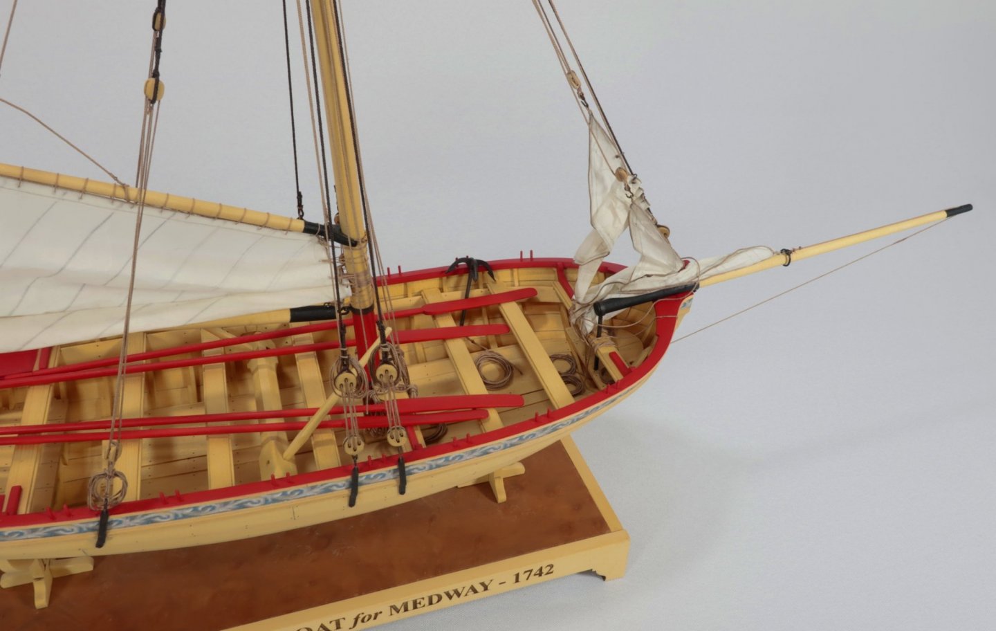
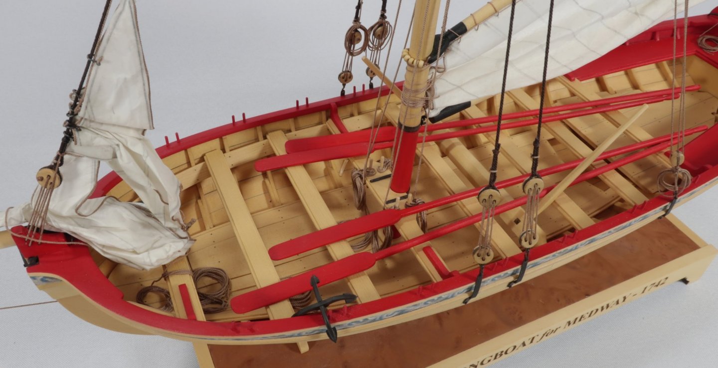
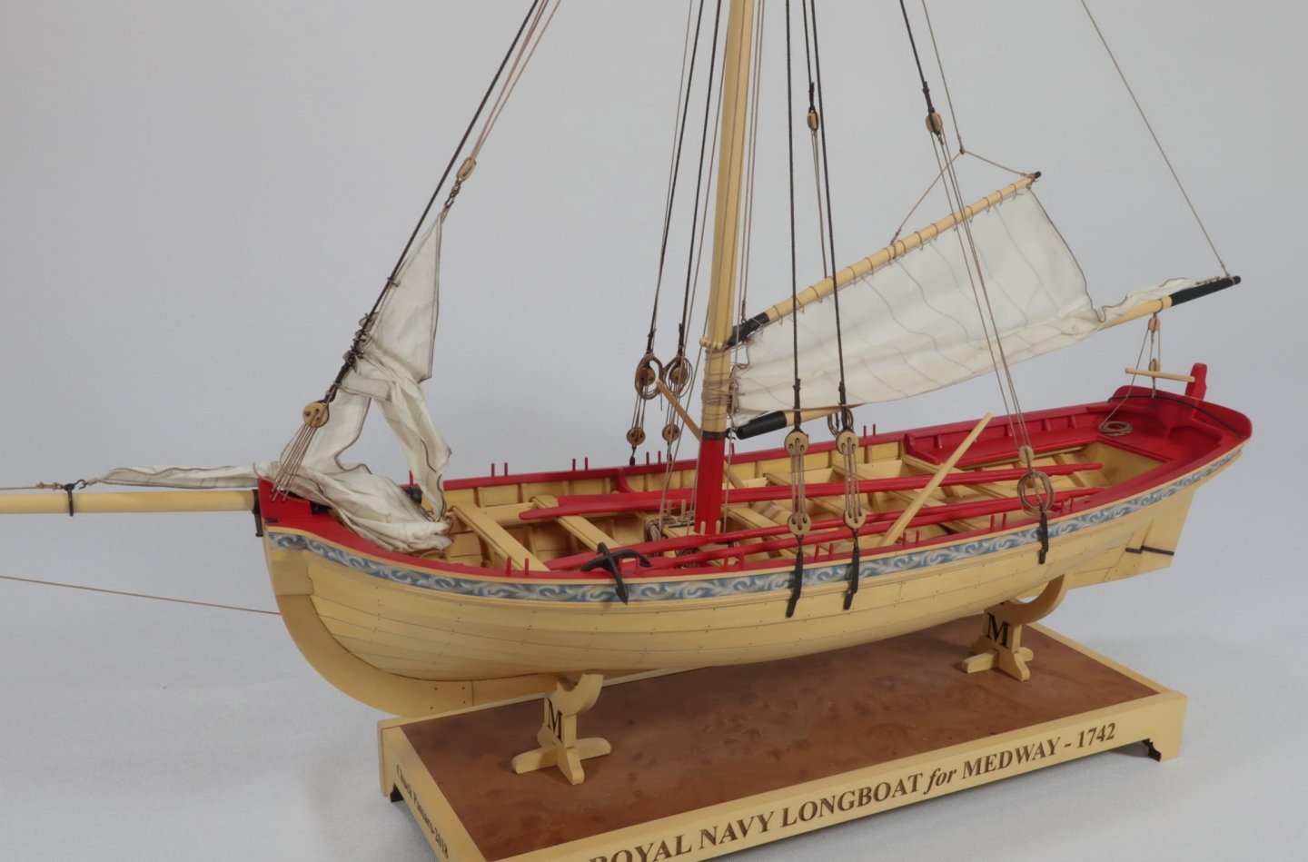
Tom and Bill came by my shop a few days ago. Tom dropped off the Longboat model with the sails all finished. What a masterful job he did on these sails. I think it adds so much to the overall presentation. Anyway....I took some photos from various angles so you guys might see them in more detail. Thanks again Tom. In addition....<Medway Longboat kits are now in stock. I believe there are only 4 left now. But I will make more soon. Chuck


- 421 replies
-
- 15
-
-

-
- medway longboat
- Syren Ship Model Company
- (and 1 more)
-
That is great news.
-
A couple of weeks probably. I am also headed down to Washington DC and the Smithsonian soon I will be be away for a few days. Im leaving on the 16th. I probably won't have it ready before I leave but I am gonna try. chapter 7 has a ton of parts and laser cut sheets as you can imagine. Its probably the biggest chapter so far. I started cutting parts yesterday for the first batch. Chuck
-
Really looking nice Druxey. What a beautiful model. Will you be painting any parts or will you leave it all natural wood?
- 433 replies
-
- 5
-
-
- open boat
- small boat
- (and 1 more)
-
HMCSS Victoria 1855 by BANYAN - 1:72
Chuck replied to BANYAN's topic in - Build logs for subjects built 1851 - 1900
Pat that looks fantastic. Well done with the bell. Metalwork like that is difficult for me and watching you put all the metal bits together on your model so well is inspiring me to give it a try at some point. Its a whole different animal for me but you make it look so easy. Chuck- 1,013 replies
-
- 2
-
-
- gun dispatch vessel
- victoria
- (and 2 more)
-
The larger are 1 29/64.... the shorter on the q deck are 1 11/64" Carriages too.
-
Chapter seven materials list.....Materials List for Winnie seventh.pdf Remember there is no Chapter six materials list for Syren Parts because its just the guns. Basically you need twenty four cannon (1 15/16" long) and the corresponding carriages.
-
The Board of Directors of the Nautical Research Guild is pleased to announce the 2021 Photographic Ship Model Review & Juried Competition. The last NRG model photo competition was in 2015 (click here to view the winners). The competition has been updated to make it easier to submit your photographs. All files will be submitted on-line…no more downloading the files to a DVD or driving to the post office. Entrants will also receive a written review of their model. Gold, Silver and Bronze medals will be awarded for the First, Second and Third place models in three categories: Apprentice, Journeyman and Master. A Best of Show medal will be awarded to the best Gold medal winner and ribbons will be awarded to models with qualifying points. The competition is open to Regular Members in good standing of the Nautical Research Guild. If you are not currently a member, join the Guild for as low as $40 and enter the Competition. The fee is only $30 per model entered. Winners will be announced at the Annual Member’s Meeting in the Fall. To view the complete rules and download the Entry Form, click here. The forms are in PDF format and can be read with Adobe Reader. Click here for help with viewing PDF files. It has been a long time between competitions. You have had plenty of time to build some great models. The Board looks forward to seeing your entries soon. Click here to learn more about the competition, read the official rules, and submit your entry.
-
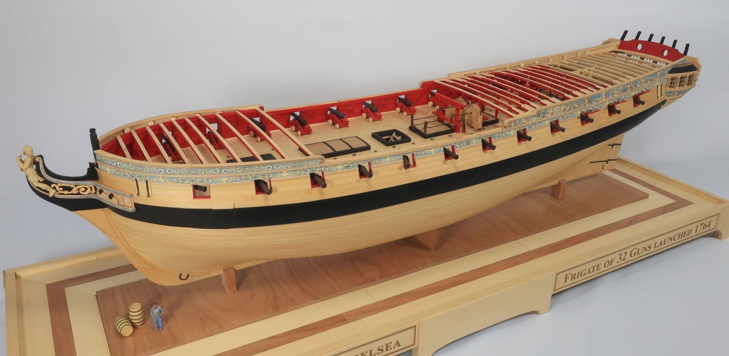
The base is just as important as the model itself. A poor base and case can really degrade the overall look of a project. Chuck
- 1,784 replies
-
- 7
-
-
- winchelsea
- Syren Ship Model Company
- (and 1 more)
-
You dont really have to. Its up to you. Some people like more filler at the bow and others dont. For fairing…just try many methods and approaches until you find one that works best for you. Its not a fun job so try and find the most comfortable approach for yourself. Chuck
- 274 replies
-
- 2
-
-
- Cheerful
- Syren Ship Model Company
- (and 1 more)
-
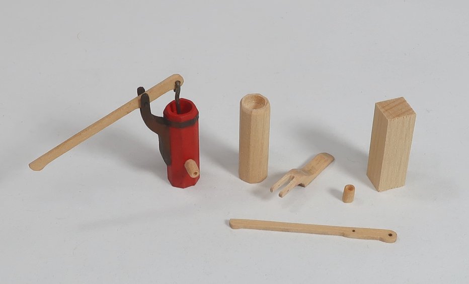
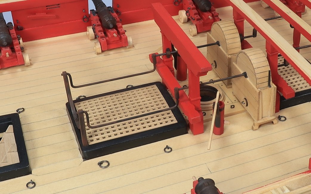
Finished the elm tree pumps which effectively finish chapter 7. I will get the printed chapters ready this week for both chapters 6 and 7. I will also be working on getting the parts for this chapter ready within a week or so. There are a whole bunch of laser cut parts for this chapter and more than usual so it will take a little while. There are probably more laser cut parts in this chapter than in many complete kits. Making the elm pumps is pretty straight forward. Same as those for Cheerful and other kits. 1.You can use a 7/10/7 ratio to transfer lines to each side of the 3/16" square pump tube. This will help you turn the 3/16 x 3/16 x 5/8" boxwood strip into a neat octagon. But its such a short piece that like me you may be able to eyeball it and sand it to the octagon shape with a nail file. Carefully file the tube to an Octagon using the lines or your eye as a guide. Drill and bore out the top of the tube to a depth of about 3/8". Carefully use a bit that will leave the pump tube walls not too heavy. 2. File and shape the bracket for the handle. The part that sits against the pump tube is tapered thinner so it fits on one facet of the octagon. Use a slotting needle file 1/32" thin or less to file the slot in the top to a forked shape. This will accept the handle. 3. Place a 1/16" x 1/16" strip in a dremel to round it off for the spout. Using an emery board this takes only a minute. This will become your pump spout. Drill a hole into the end before parting off a 5/64" long spout. Glue it to the pump tube. All pieces can be painted first. 4. Using some black tape or even painted painted black paper, cut it into thin strips about 3/64" wide. This will simulate the iron band at the top of the pump tube. 5. Glue the bracket into position. You could paint it black like I did or leave it natural. 6. Insert a length of 24 gauge black wire into the hole on the end of the handle. Like an eyebolt. Insert the end of this long wire into a pre-drilled hole in the bore of the pump tube. Adjust the length of the wire until the other pivot-hole in the handle sits in the bracket nicely. The handle should be in the downward position to be correct. 7. Finally insert a small length of 28 gauge black wire into the bracket hole and through the handle to lock it in position. Snip it off on both sides so it stand proud of the bracket's surface just a little bit. Finishing all of the deck fittings and beams does really change the overall look of the model. Its starting to fill in with all of those wonderful details. This makes you want to add more of them which I will do shortly. Chapter 8 will be doing this same work but under the forecastle beams. Finally get to make the stove and other bitts. Just look at how the model is filling out nicely with detail. Just try not to snag those elm tree pump handles as you work on other stuff on the model!!! Boy that forecastle area looks so empty!!
- 1,784 replies
-
- 33
-
-
- winchelsea
- Syren Ship Model Company
- (and 1 more)