MORE HANDBOOKS ARE ON THEIR WAY! We will let you know when they get here.
×


michael mott
-
Posts
5,195 -
Joined
-
Last visited
Content Type
Profiles
Forums
Gallery
Events
Everything posted by michael mott
-
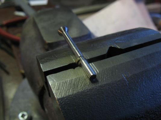
 Thanks for all the kind comments. It was neat to go back down memory lane on the Bleriot. My tool for the Dremel seemed to work OK The shaft is a really tight fit into the 23/32" hole, I will add a locking screw for security for future work. it did work well shaping the cutting faces on the valve seat cutter. I have done the first seat, and then I needed to make a new split holder for the valves so that I could machine them to length, I decided to make the holder the exact length of the valve stem so that it would be easy to slip the valve in then trim off the excess, it worked fine for the first one, the second valve would not slide through the same as the first. Now I understand the Go- No-go gauges and what such a small difference at a couple of tenths of a thou make. I ended up fiddling with it for a couple of hours, and working on the valve polishing off the offending .0002" which was not easy, I probably could have made a new valve in the same time, but did not want to reset the tooling. the valve seat cutter worked well but slower that I thought it would. cutting the bevel from .093" to .120" diameters The new springs are better. I will take some pics today of the cutter and of the slit holder to the valves Michael
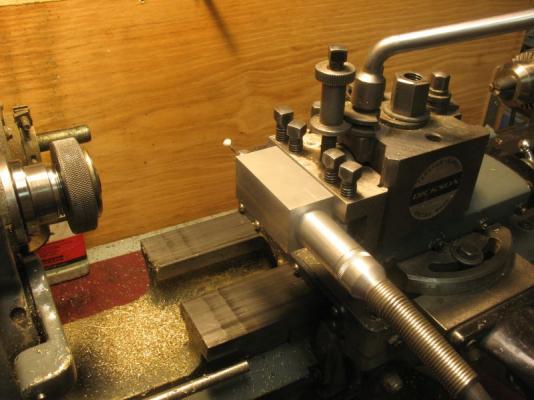
-
I get tired just watching you blaze on.... great details on the ladders. Michael
- 956 replies
-
- 4
-

-
- andrea gail
- trawler
- (and 1 more)
-
You're kidding me right?......anyone who can do the amazingly tiny work that you do cannot possibly claim to have such fingers. Michael
-
Nils just when I think how many more lines could there be, you go right ahead and show us some more. Making rope and growing the fibres for all that rope must have been a huge business in the 17th to early 20th centuries. Michael
-
Jack, no I have not been there it was all by correspondence. I have and old book on aeronautical engineering with an introduction in it by Orville Wright. It is "Practical Aeronautics" by Charles Hayward published by the American Technical Society in 1917 first published in 1912, it has the complete plans for building the Bleriot, along with lots of photographs as well. I used it as my main source. Row, I am already on it. I made all new springs and new keepers that were just .002" smaller in diameter on the small diameter which allowed the springs to slip over them more easily. I am just in the process of jigging up my Dremel shaft into a fitting that I can hold in the lathe tool post so that I can accurately cut the facets for the valve seat cutter. On the week end I saw a micro drill like one of these there was absolutely no vibration and it had a fabulous chuck. something like this is now on my wish list. Michael
-
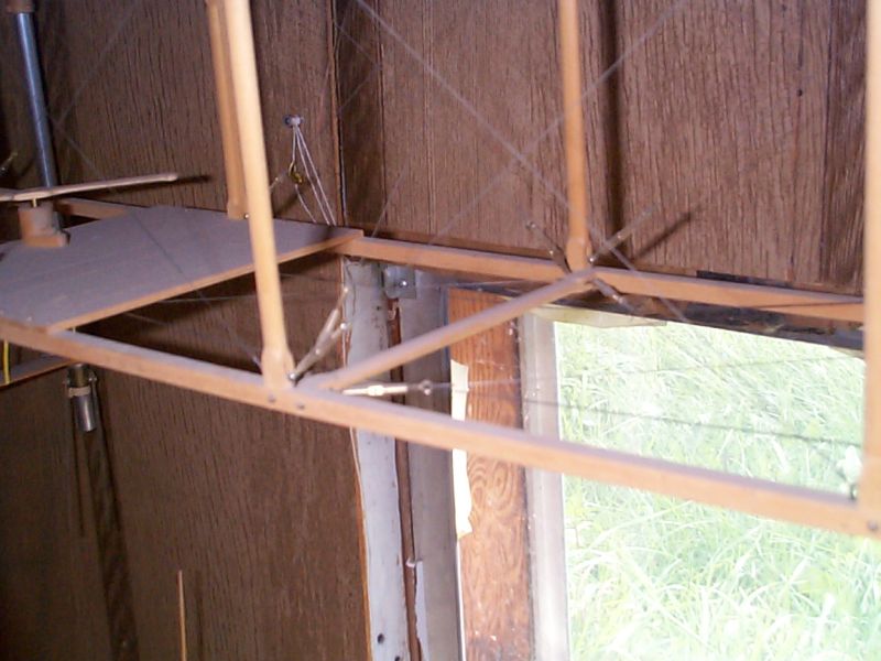
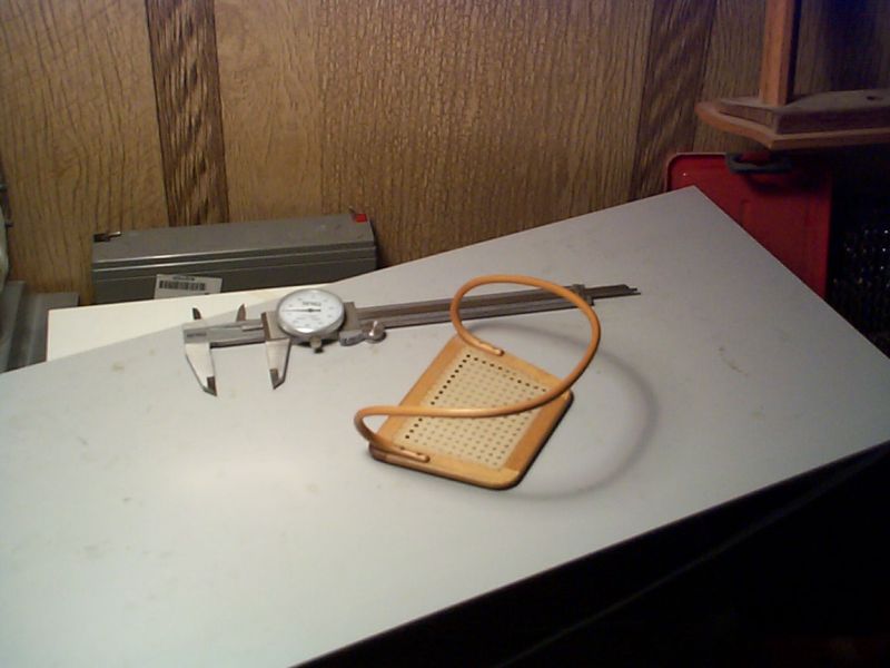
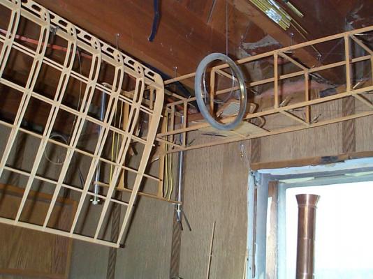
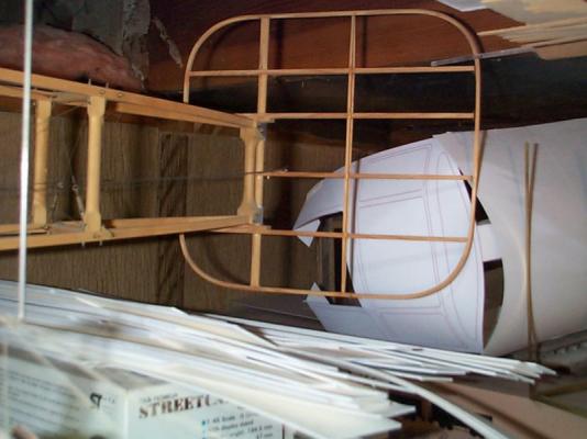
Hi Jack, I studied, that aircraft along with the one from Old Warden in England. my model had wing warping as well. I never finished it and gave it to the local air museum, along with all the drawings and research photographs, the drawings were from Old Rhinebeck. here are a few shot which is all i have. I was particularly pleased with the "canework" on the seat. the bentwood was formed from layers of birch veneer formed over a bent piece of stainless steel. After the layers had cured for about a week i filed and sanded the laminate to shape. The canework was woven from some plastic bag material from a local shoe shop, it had just the right tan colour. I cut strips of the plastic about 1/16th wide then stretched it out until it reached it limit of elasticity, it was then reduced in width to about 1/32 and had a slight convex cross section. it took two tries to get the weaving right, and the toughest part was keeping the strands all the same way up with the curve of the "Cane" on the top side. This would be a great way to make one of those cane seats in one of the Adirondack Guide boats Michael


-
Hi Andy Thanks for the tip. Michael
-
Thanks again for the likes. Carl the springs are made from some .011" diameter music wire which is number 2 music wire gauge, incidentally I have 3000 feet of the stuff, I bought a 1lb roll of it back in 1970 for the wire trusses on a 1/4 scale model of the Bleriot 11 the first plane to cross the English Channel. So if anybody needs some let me know.. Druxey glad I was able. These ones were more fiddly than miserable. Michael
-
Buck, I have no Idea. This is all trial and error. I am flying by the seat of my pants on this one. Michael
-
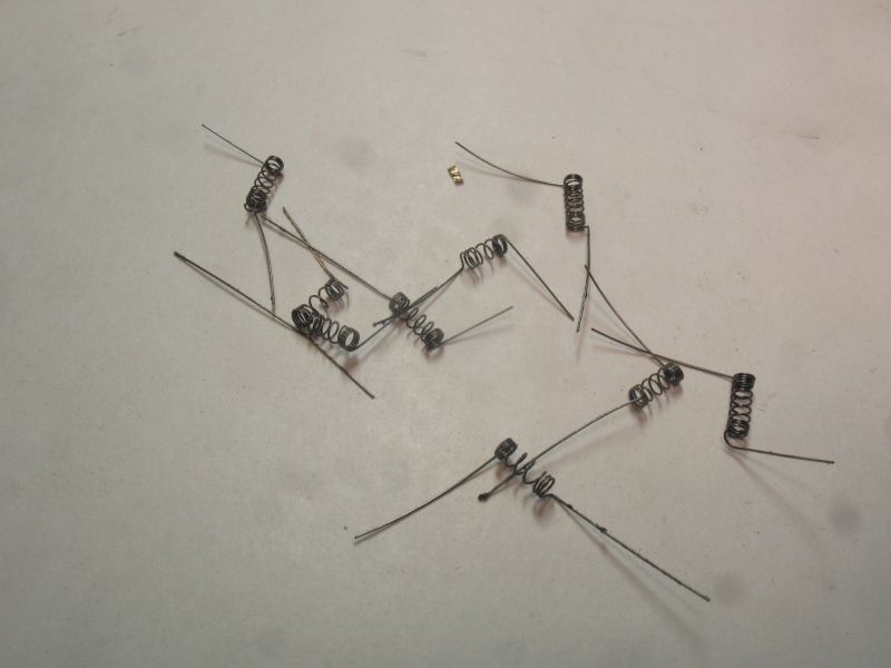
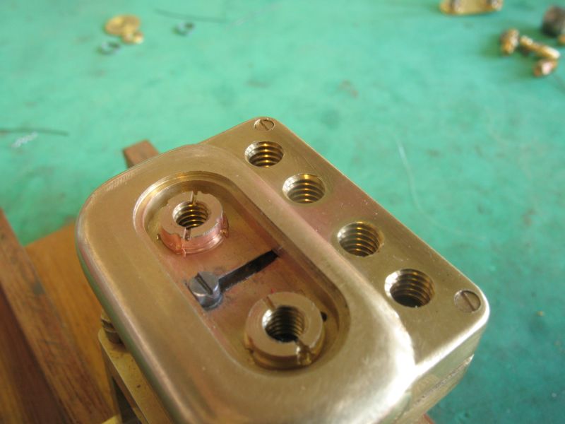
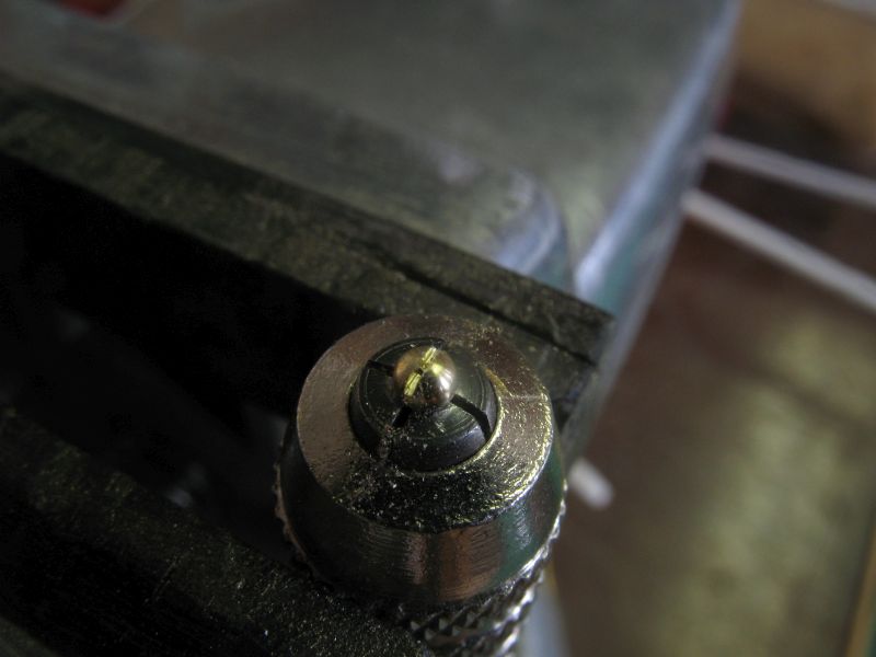
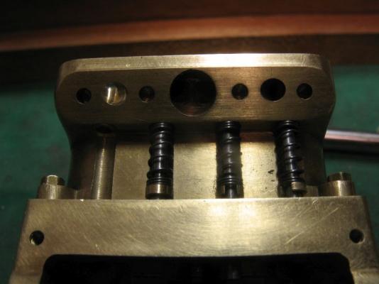
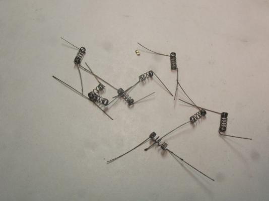
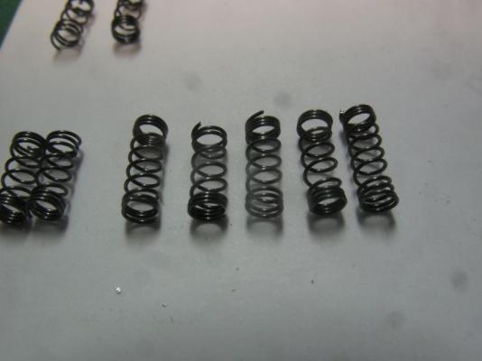
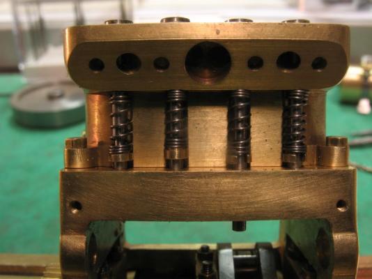
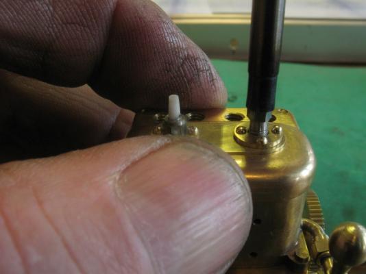
Bob, Carl, thanks for the kind words. And to all who visited and showed their appreciation. Just a small update. The trial shaping of some springs and the fitting of the valve spring keepers. The first picture shows test fitting the valve into the .052" slot of the keeper, they are .110" on the major diameter and .081 on the minor diameter and .070" high. The raw springs, these are just freehand off the mandrel which is an .067" drill which creates an internal diameter of .081" Trimmed up a bit. Trial fitting on the block. Now I need to get some consistently formed springs made. The second from the left is the best one so that is the goal. Michael
-
I too am looking forward to some updates. Michael
-
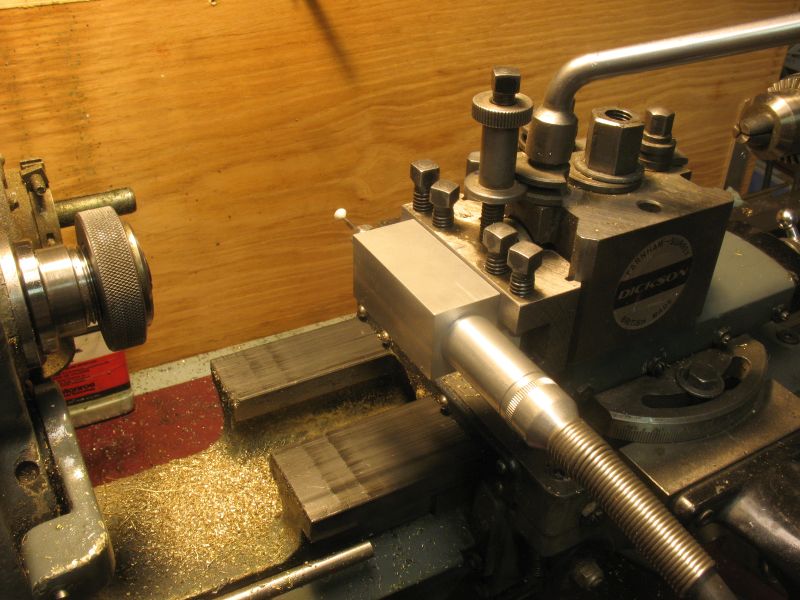
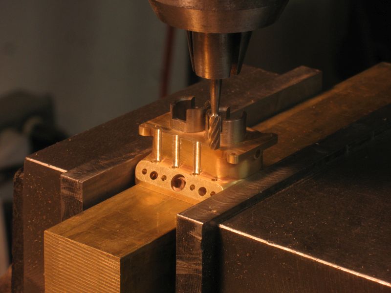
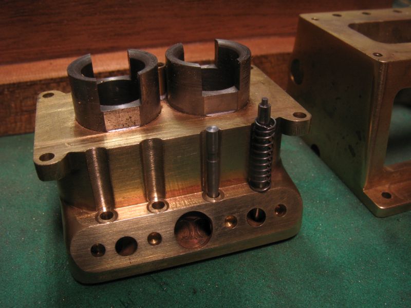
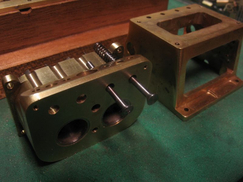
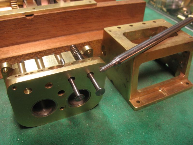
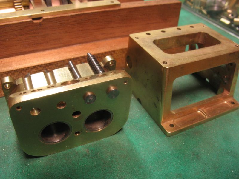
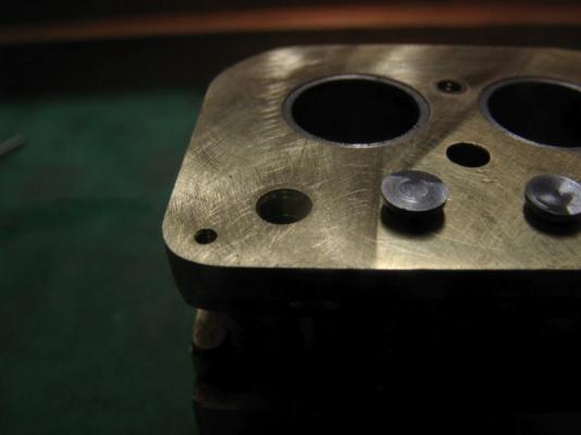
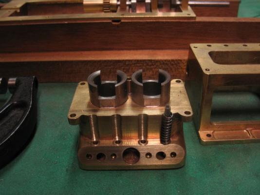
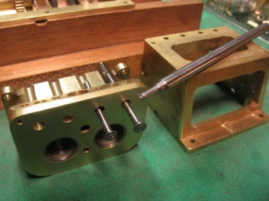
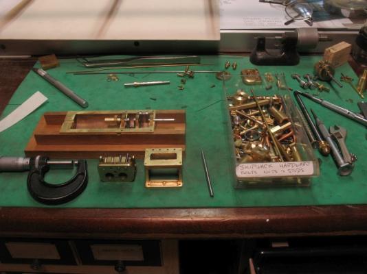
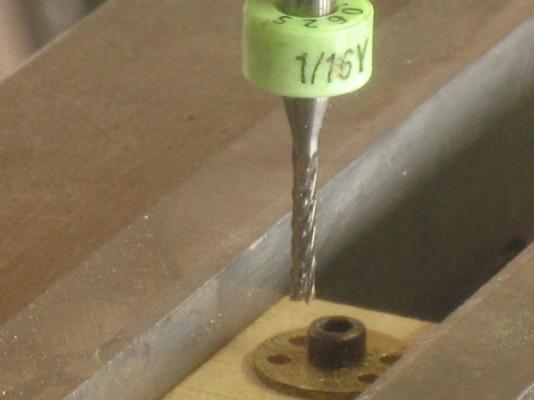
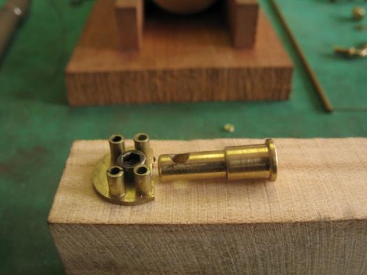
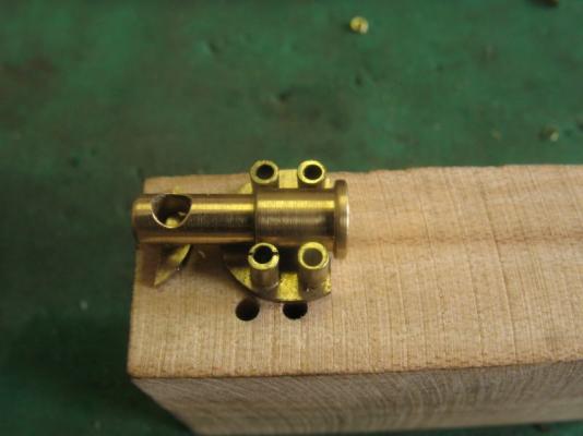
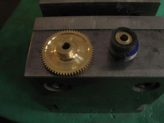
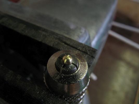
Thank you all for your continued encouragements, and likes Igor that video is just amazing and humbling all at the same time, I don't think I have the patience for something as complex as that. Well I am back at the library as the home system is still not working, I am told I need to upgrade the service equipment that communicates with the tower!?? I have started the work on the valves now. first the wall of the water jacket needed to be relieved a little to clear the .100" coil springs that return the valves after the cams have lifted them. I used a .125" Dremel mill after resetting the indexes so that I could follow the numbers for the drilling. The valves are turned from some 1/8th drill rod /silver steel and the cutter reduced the diameter with a single cut I simply fed the material out of the collet and kept the cutting close to the collet. these two are the first test parts to get the dimensions correct, slide fits etc. and the machining sequences, this is the reason for all the extra bits in the scrap boxes. The valves are .665 long and the stem is .062 the spring keeper section is .047" in diameter just visible on the shorter valve stem. While I had the tool set up for cutting the bevel and reducing the diameter at the same time I used the same tool to turn the blank to make the valve seat cutter this is just a bit more complex because it needs to have the cutting faces cut in yet then will be hardened and tempered. It will be used in the drill press to cut the seats. the next picture shows the valve pushed in and the flare is visible waiting for the body to be cut. The last picture shows just some of the left over bits from all the work so far, in the little drawer marked Skipjack hardware. I need to sort it all out into one of those plastic bead trays with the curved bottom compartments. Michael


-
Bob that is looking really sharp, i like the mahogany trim it sets the cabin off well. Michael
-
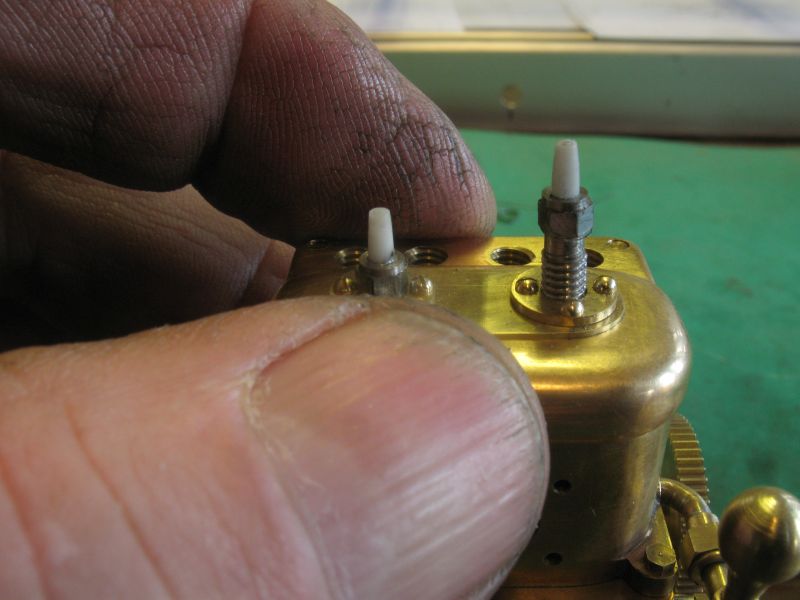
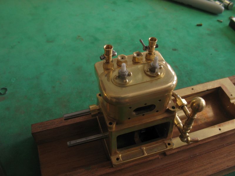
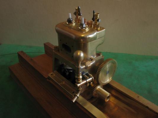
Thanks to all for the likes and comments Today I mounted the waterpump with 4 00x90 hex bolts The other milestone was to finally get the head mounted. and made a spark plug wrench. Michael


-
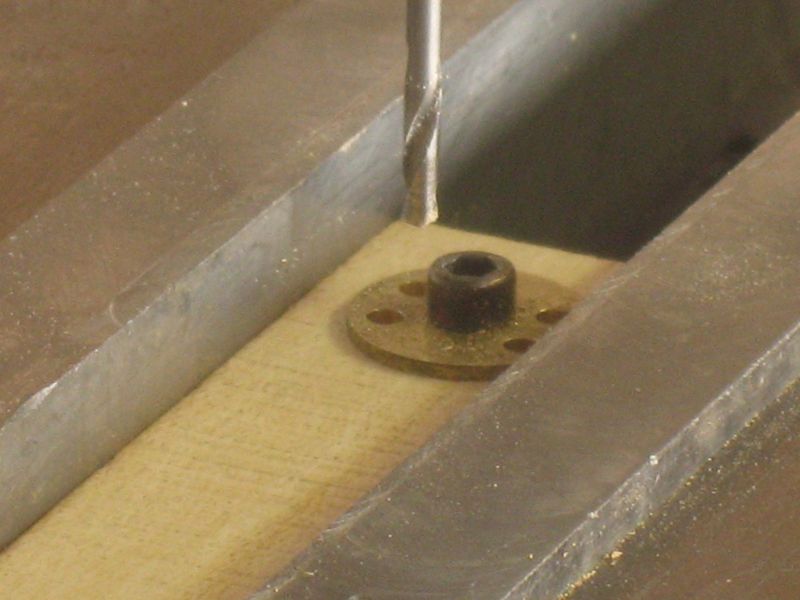
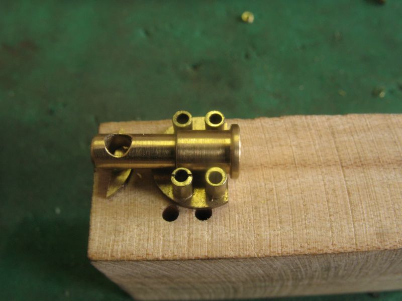
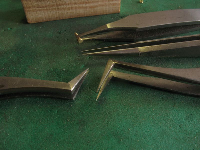
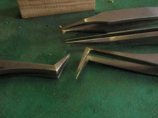
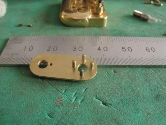
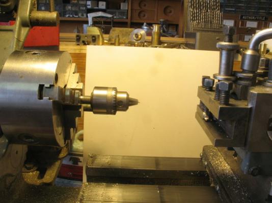
Thanks for all the many likes and fine comments . "How do you hold on to tiny round metal pieces when you are assembling? I've had a problem lately with the tips of tweezers pinching round or small metal pieces and launching them to some parallel dimension." I use a variety of fine tipped tweezers like these I started working on the pump body and decided a a different approach than the first one. First I parted off a disc of brass from some 3/8 bar stock to make the base sheetthis was drilled for a clearance for a 2x56 allen head cap screw, this was then bolted to a piece of maple and set up in the mill to drill and tap 1x72 which is .073" in diameter. My reason for parting off some rod is that the machining qualities of the bar stock are much better that the .025" sheet, the bar stock being free machining and the sheet rather gummy. The plate was then fitted with some .073" rod that had been threaded and drilled out to .047" which will let me use some 00x90 bolts to fix it to the crank case The next picture shows the body temporarily positioned, because the tubes are threaded into the back plate and I want the whole assembly to look like a casting I will solder the lot together. The back plate still need some final shaping, I will do that after it is one piece. That's about it for today. Michael

-
Hi Mark, usually the very tip is set the drill stated diameter and at the end of the flutes at the top of the shank the diameter is a bit smaller, at least that is what I have found. Had I wanted the hole to be exactly .25 I would have either drilled it 1/64th smaller them reamed it or bored it out and measured it with some telescoping gauges. Measuring a drill across the tip is a bit tricky a micrometer seems to work best for me. To get a good tight fit with the larger drills I usually drill them out with a smaller drill first say 1/16 or so smaller then drill with the size that I am wanting. with the smaller drills in wood I find that the wood sometimes has a tendency to form a hole that is a smidgen smaller than the drill almost as if the wood is springy and that the fibres are pushed aside a little as well as cut. This is more pronounced when using regular general purpose drill bits. the specially ground Forstner bits cut the fibres about the perimeter first befor the body of the drill removes the bulk of the material. Michael
-
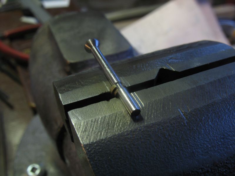
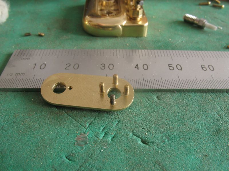
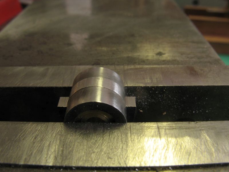
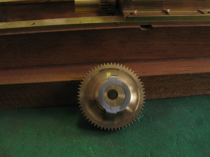
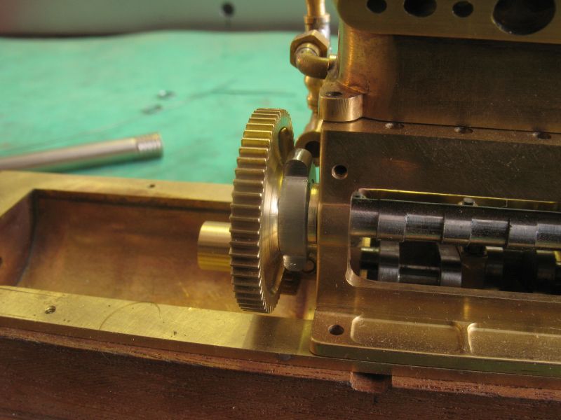
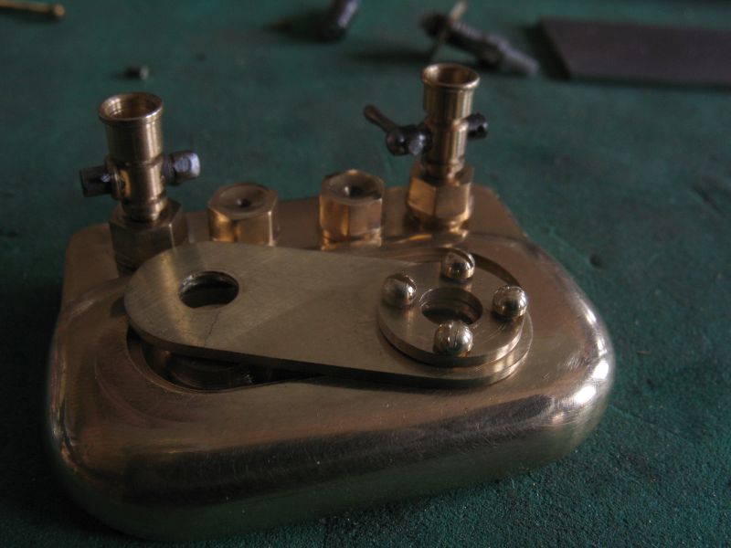
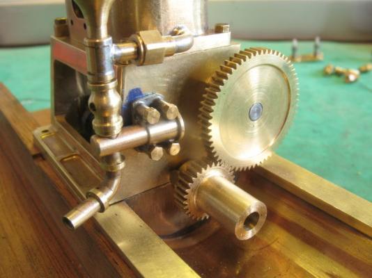
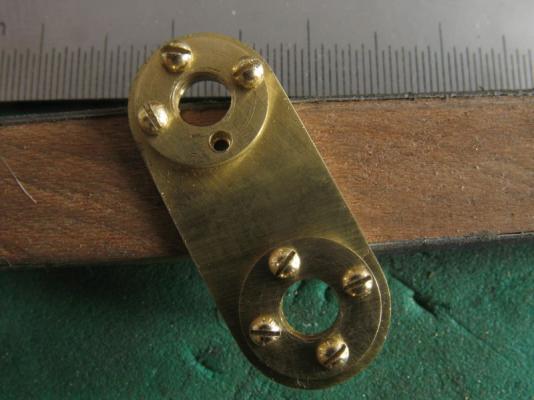
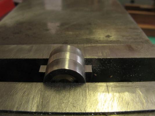
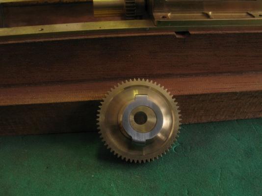
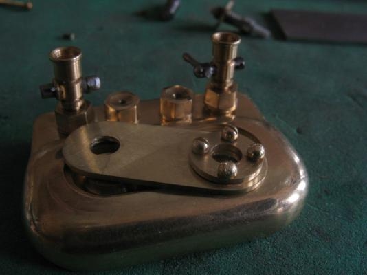
Thanks for all the fine comments, the smaller these parts get the more complex it seems to be to make them. I had to come down to the library, because our home internet has crashed due to a problem at the tower that feeds our broardband. It is fun to work on such a fast system. After drilling and tapping the second set of holes I removed the plate to open up the circular one to complete the installation of the new screws the smaller heads do look better even so they are still really a little on the large size scalewise. The top larger set will be replaced. the plate was clamped in the vice to cut off the extra length of the screws... more bits to add to the growing scrap box that has been generated by this build. Overall shot of the plates and plugs If I had some 000x120 screws and the taps and dies then I would be able to make them a little smaller. Oh well. For a change of pace I started to make the water pump cam parts, I machined some 1/2 inch diameter stainless steel into a .100" disc with a drilled 1/4 inch hole, the reason I just drilled it was to see if by drilling it straight with the 1/4 if it would drill just slightly larger by about a thou or two, and it did which caused it to be a nice slide fit over the .25" diameter cam on the gear. I turned up a couple of sleeves from some drill rod and hardened them as filing guides for the excentric. Step one is complete, next I need to silver solder the arm link to connect to th piston. Michael


-
Denis, I really enjoy all the small details that you keep adding, each one is a small model in itself. Michael
- 956 replies
-
- 3
-
-
- andrea gail
- trawler
- (and 1 more)
-
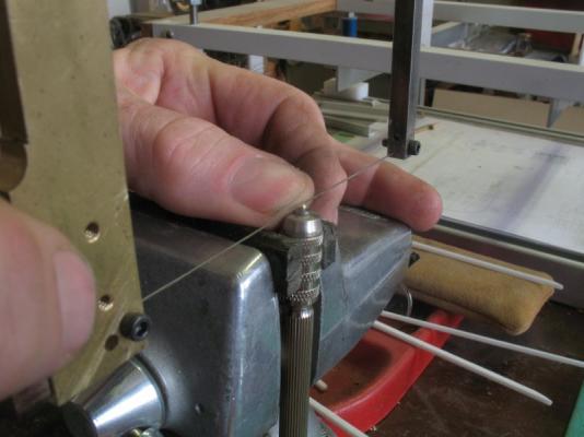
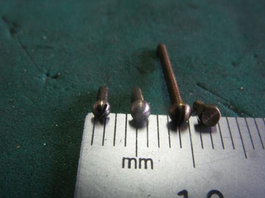
Thanks Kees, and for all those who added a like to my previous set of pictures. today I modified some 00 x90 hex head brass machine screws, cheating I know. I chucked up a small drill chuck in the Myford lathe to hold the small screws. The round head 00x90 from the suppliers are .087" max head diameter which was a bit large so I turned down some hex ones I had to .078" diameter then filed the round with some fine files and then gave them a burnish with a clockmaker's burnish, Next the screw slot was cut with the jewelers saw. After drilling and tapping the circular plate I discovered that the round head screw were still a bit too big, also the holes in the circular plate still needed to be opened up for a clearance for the 00 x90 screws. I reduced the diameter of the screws to .071", which is about as small as I want to go with the 00 x 90 which has a max thread diameter of .060" Left one is .071 next is .078, next is the commercial round head at .087" and the hex type that I used as the base for the modifications. Tomorrow I will finish the other plate and the rest of the screws down to the smaller diameter. Michael

-
Chuck your planking work is outstanding! I hope I am able to get closer to this standard on my next hull. Michael
- 1,051 replies
-
- 2
-
-
- cheerful
- Syren Ship Model Company
- (and 1 more)
-
ancre Le Fleuron 1729 by rekon54 - 1:24
michael mott replied to rekon54's topic in - Build logs for subjects built 1501 - 1750
Those eye-bolts are a lot of work even with the tools that you are using, the end results are great. Michael -
John what a beautiful looking hull, super job on the planking. Michael
- 745 replies
-
- 1
-
-
- francis pritt
- mission ship
- (and 1 more)
-
Thanks for all the likes and for the kind wishes for Judy. i read right your an Englishman abroad with skill,s like yours i,d say Sheffield lol Gary, well it was St Marys Hospital Paddington right next door to the Great Western Railway Station. (or as some say God's Wonderful Railway) Then I grew up in Acton W3 in West London..... trial and error is a wonderful teacher, I have lots of scrap boxes that have accumulated over the years, and also encouraged by the right folk when I was young. Michael