HOLIDAY DONATION DRIVE - SUPPORT MSW - DO YOUR PART TO KEEP THIS GREAT FORUM GOING! (89 donations so far out of 49,000 members - C'mon guys!)
×


michael mott
-
Posts
5,200 -
Joined
-
Last visited
Content Type
Profiles
Forums
Gallery
Events
Everything posted by michael mott
-
 Gaetan not only is the carving exceptional, the photography is superb. Michael
 -
Bob This site has a number of specialty taps and dies, pricey but good quality I suspect, I am always concerned about ensuring that my taps and dies are of the best quality, I have found sometimes that the cheaper ones are not ground threads and have a tendency to tear the material a bit even with good cutting fluids. since I am only cutting one or two and in brass i might just thread-cut some 1/8th inch drill rod and make a small tap and thread up some brass rod at the same time. then they will match. Michael
-
Bob I did not know that such a die existed, I shall have to look now for instrument taps and dies, but it makes sense it just had not occured to me. so thanks again for another great tip.. Michael
-
Ripping thin planks
michael mott replied to Peaksol's topic in Modeling tools and Workshop Equipment
What sort of blades are you using? Michael -
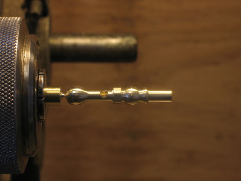
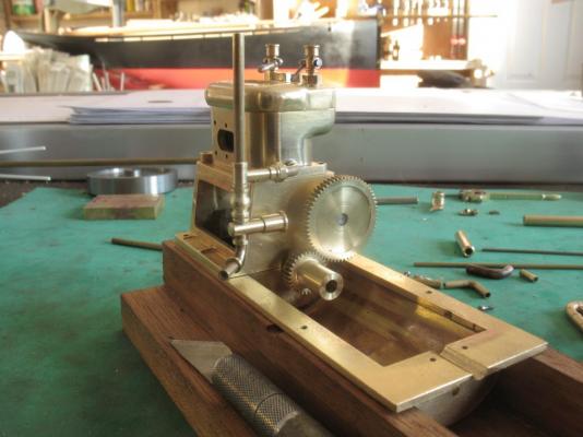
The testing of various ways of dealing with the small fittings is now completed for the most part, and the final model parts in scale are coming together well. That said I am contemplating the false union at the junction with the cylinder and wondering if I can actually make one that works as a real union. Cutting a thread on some 1/8th diameter is not a problem usually the standard thread in imperial being a 5x40 the only problem is that at this scale that is an extremely coarse thread. The elements are now in scale and the tubing is 3/32. I am thinking that if I can make a thread cutter that will cut say 5x80 then that would be a much better size for the union, the concern that I have is if the whole lot were soldered together then separating the cylinder from the crankcase would be problematic, because there would be too much piping hanging off the cylinder and therefore easy to damage. In making the union actually work like a union it eliminates that problem. The saga continues. Thanks to all who are following along and commenting, providing useful tips, and for the likes. I am happy that some of the methods I am using are useful to some of you. it is the least I can do for all the knowledge I have gained from you all who share your methods and tips. Michael

-
Ed lovely work on the gold painting, you do indeed have a steady hand. Michael
- 3,618 replies
-
- 1
-

-
- young america
- clipper
- (and 1 more)
-
Ah yes the frustration of compound curves. Makes one wonder how we ever got boats like skiffs and Dories doesn't it. Nice work of the roof and the details of the fridge, but is the beer cold inside? Michael
- 956 replies
-
- 2
-
-
- andrea gail
- trawler
- (and 1 more)
-
thanks for all the likes and encouragements. Denis it is one of the things I have thought about. the issue would be the size of the tank and the volumes. a good filtering system and small pump might still be the best option, there is lots of time for experimenting. Michael
-
Cutty Sark by NenadM
michael mott replied to NenadM's topic in - Build logs for subjects built 1851 - 1900
I like the approach that you have for your work Nenad, you keep at it until you find the right solution. Michael- 4,152 replies
-
- 1
-
-
- cutty sark
- tehnodidakta
- (and 1 more)
-
You are doing a great job on the construction Kevin, very clean work. This raises the point that the boats made with the less durable woods were probably built for a particular working life time-frame whereas the one built with the more durable material might have been built more as a recreational boat versus a working boat. Just my thoughts on the reasoning for the differences. Michael
-
Mike the strings are very innovative, what I like about this method is that our eye is very discerning at catching irregularities in the flow when there are a group for reference. Your strings look like 3D lofting in miniature. Michael
-
Danny sagging and other issues aside your rigging looks superb, very nice thimbles as well. I am curious as to your sequence for making them, bore first then shape with files and or form tool? then part off? Michael
-
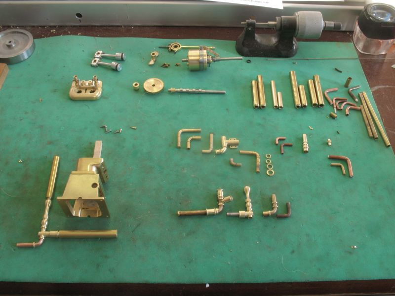
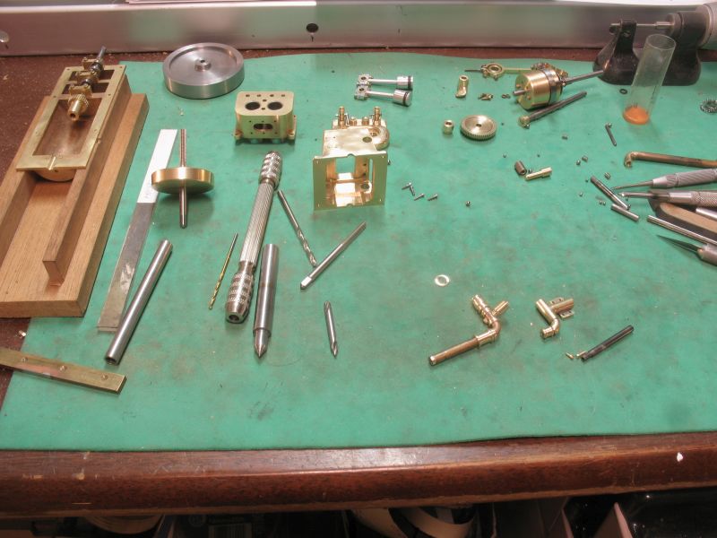
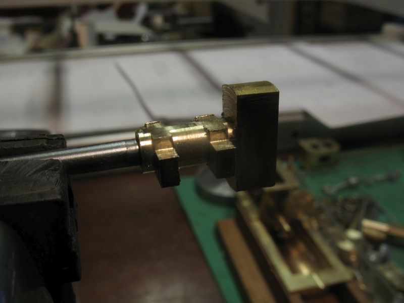
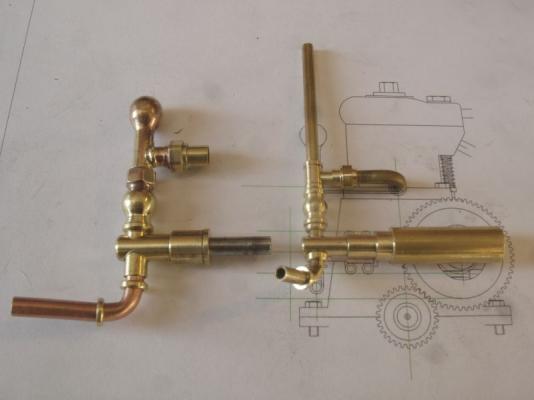
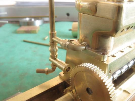
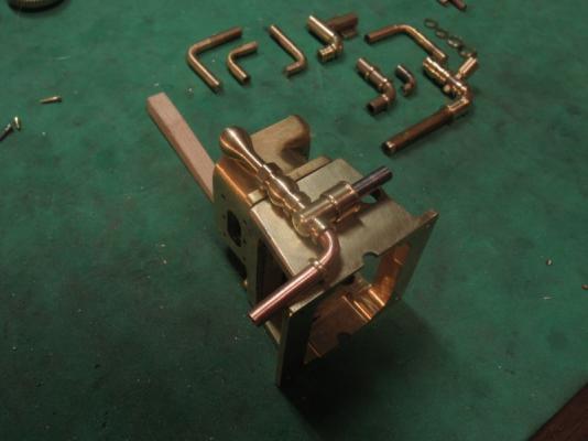
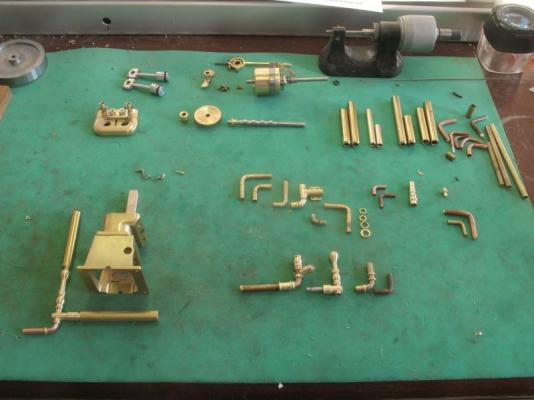
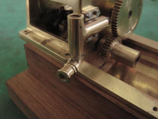
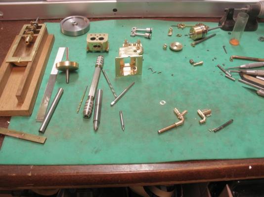
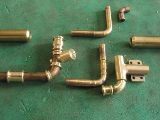
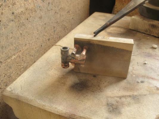
Hi Carl, I agree with your thoughts, I think that if I keep things consistent and have a good general flow then I should be OK. I can push a fair bit of water through the .093 holes with a good pump and since I am not going to be running this engine for long stretches I am confident that I will be able to get enough cooling. Thanks Druxey, I do have the small set of coils spring pipe bender that I purchased some time ago but they only work for gentle curves, I have done some more experiments with the styrene rod as a filler as suggested By Bob. The combination of the heavy walled brass tube benders that are bored to the pipe size plus filling the tubes with the styrene have greatly improved the quality of tight elbows. The styrene gets trapped and a quick play of the propane torch over the elbow pops most of the styrene out then after removing the blobs at each end of the bent tube a little more heat and the residue flames off, leaving a good bend and flow through. Thank you Mike, Mark, Steve , and Nils for your very complimentary comments. A sincere thanks to all who have shown their appreciation by pressing the like button. I am continuing with the experiments with the various shapes and components for the piping and valves. I am gathering a fair collection of bits for the spare bits box. The parts to the extreme bottom left hand corner are the present iteration, that i am working with. the hex sections have been filed instead of adding in some sections of hex stock this eliminated the need for threads etc and is quick enough to do with a few strokes of the fine file. I filled the four mounting holes with some 00x90 threaded rod and soft soldered them in place because they won't work with the new configuration that is not quite there yet but is getting close. I have been sorting out the stack of elements and seeing how to create the look of a number of parts screwed together but really being a solid fancy tube. here there ore the vertical part of the pump the valve to bleed off any air then the anti hammer bulb. it is bored out to accept some 1/8th inch copper pipe for the bottom elbow, and a .093 hole for the tee off to the upper union that connects the piping to the water jacket as in the one on the real engine. I am using the 1/4 inch brass rod that I purchased at home depot, this rod is nice to machine and not very expensive. By using the collet chuck instead of the three jaw I can shift the brass out as I complete each element. the collet has 6 slotted sections as part of its design which makes it easy to line up to file the hex sections. I silver soldered the tee to the bulb section, not as good as some soldering I have seen but acceptable, in this instance. Michael

-
Patrick it is so enjoyable watching your progress on these tiny masterpieces. Michael
-
Great to see you back on the ship Dave Michael
-
Denis you do seem to be going along at a pretty good pace on this build, it is looking great with all the details that you keep adding. The tube of glue fiasco made me laugh, sort of like looking for ones glasses while wearing them. Michael
- 956 replies
-
- 2
-
-
- andrea gail
- trawler
- (and 1 more)
-
Bob Thanks for that tidbit of information. I shall also do some experiment with that because I will need to move water through some small pipes And thanks to all for the likes . Michael
-
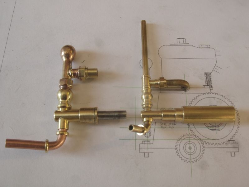
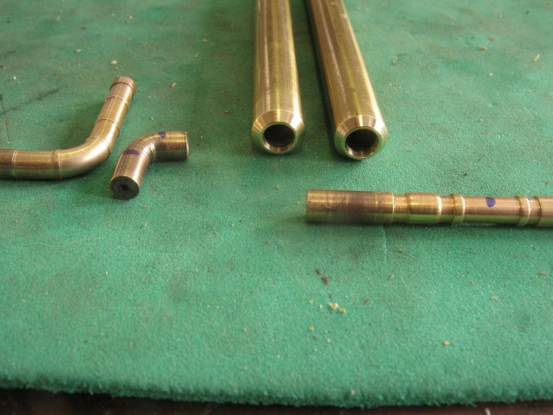
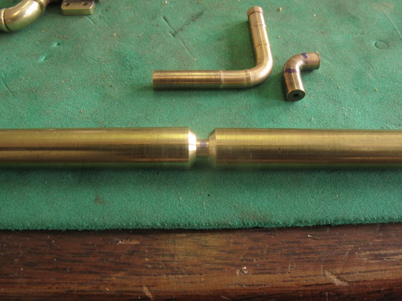
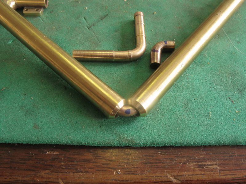
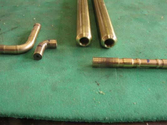
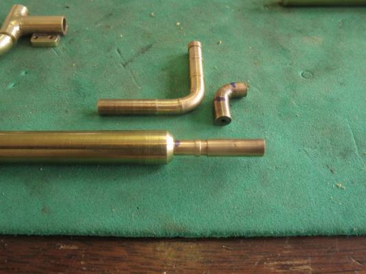
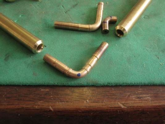
Wow! those files are pricey Druxey. the saga of the water-pump continues. I am not happy with the sizes of things and also the elbow is causing the crankcase to be raised off the sump. Mass confusion and general mayhem A number of different experiments with heavy walled tube convinced me that it is easier to bend the heavy tube than to work at drilling 90 degree holes through elbows any other way. That said I have come to the conclusion that all model locomotive engineers already know and i also knew it as well and that is one cannot scale nature, a molecule of water is a molecule of water and that is the fact of life. it also became a realization that I would not be able to get enough water through the water-jacket with a scale model pump for the same reason that nature is not scale-able. I was able to make the pump open and close with a .093 ball bearing similar to a clack valve but being realistic demonstrated to me that this approach would not work to deliver the volume of water needed to cool the head(heat cannot be scaled either. (Nigel you already knew this too) As there are two other places wher piping enters the water jacket I have decided to continue to make a scale operating water pump from the outside appearances but the actual path of the water will be through the other piping and will use a hidden pump that will be able to deliver the needed volumes. Disappointing in one sense, but that is the way the world works sometimes. experiments Now that I am on a new track I will be able to make the pump look correct, I have already done this with regard to the operation of the pistons and cylinders insider the engine and working to keep the exterior looking like hwe real engine. I have developed a couple of new tools for bending the parts of the piping. The elbow is first turned to include some flanged areas at each end, then annealed and slipped into the brass bending tools I marked the center of the elbow with a felt pen and closed the two parts. did the bend after a few tries I am pleased that this method will work michael


-
Thanks Medic, I appreciate the comment. which reminds me i really must do a little work on her instead of just gazing at her across the bench. Michael
-
Good morning Vaddoc, welcome to the club, fees are generally pretty low, looks like you passed the initiation test well enough. The lines of the planking look like you will have some sweet curves. Michael
- 253 replies
-
- 1
-
-
- ketkch
- gaff-rigged
- (and 1 more)
-
Ed that is a very interesting picture, and those strips are obviously bent to a very tight curve, I shall have to try this. I wonder if the length of time had anything to do with the very tight curve or was it just a coincidence, I shall have to do a couple of tests. The epoxy decorations looks exquisite. Looks like a fairly complex bit of gilding coming up. I suppose that using some liquid frisket or masking will be helpful when doing that. Michael
- 3,618 replies
-
- 2
-
-
- young america
- clipper
- (and 1 more)
-
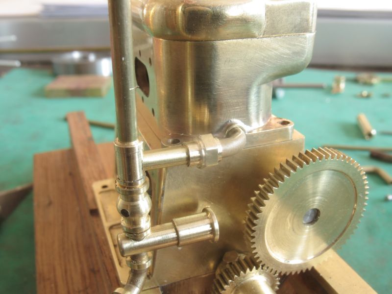
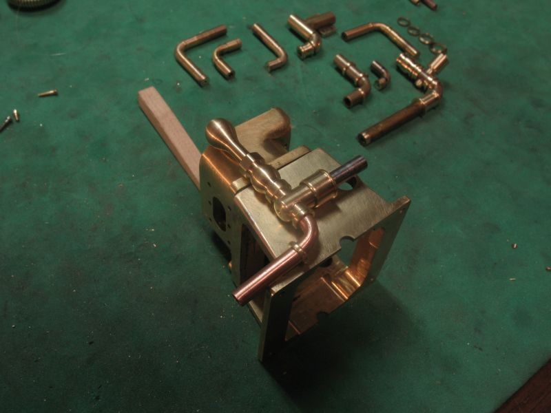
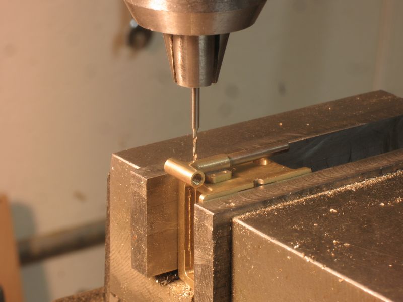
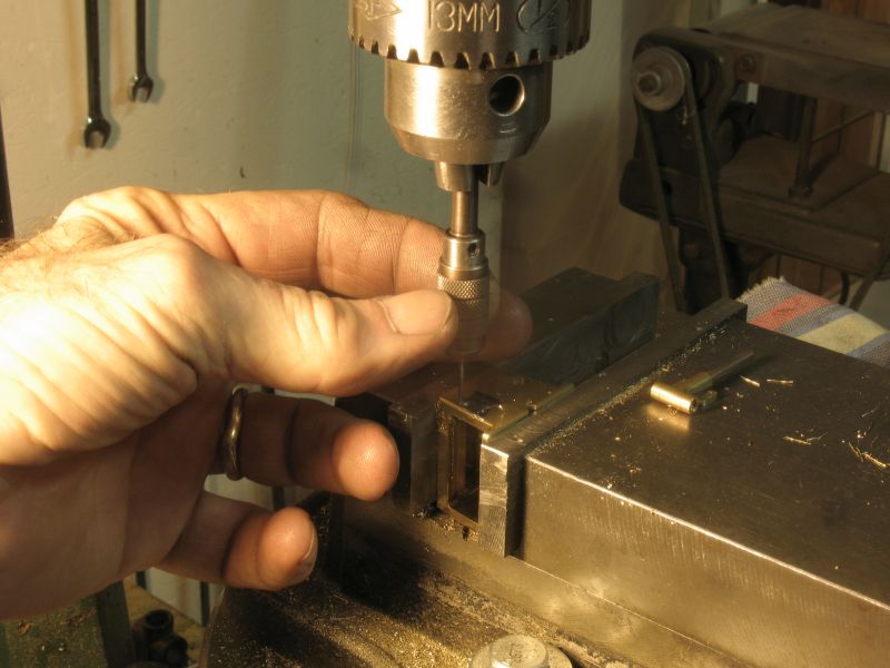
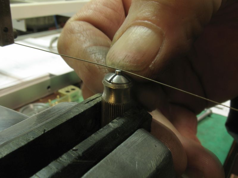
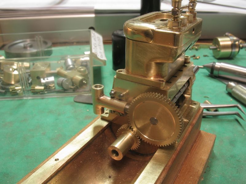
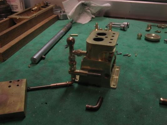
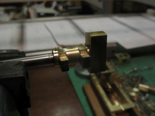
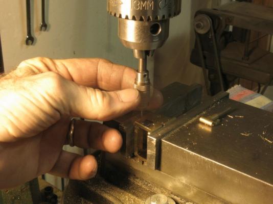
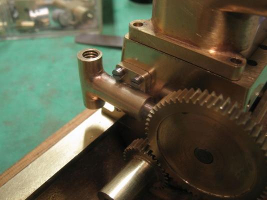
Elia, Mark, Bob, Nigel, Druxey, Carl, Denis, Remco and Mark P, Thank you all for your kind remarks. And to all who used the like button. the last couple of days have been busy with some household stuff and snow removal getting water etc. I have also been beavering away at the water pump. Attempt one ended like this attempt two ended like this attempt three "this was the turning point" (apologies to the Dinsdale brothers) I used the body of the pump to spot the position of the first hole, and because the holes in the pump body were indexed I was then able to use the same index to drill the four holes in the crank case for tapping the 00x90 threads for the mounting screws. I still might make them bolts instead of screws. As each hole was drilled I tapped it straight away. used lots of lubricant and backed the tap out several times for cleaning the swarf. using the jewelers saw to cut the slot in the screw. assembled on the crank case I now will be able to make the linkage to the eccentric in the backside of the 60T gear the piston in the pump is 1/8th diameter. Close up pictures can be brutally honest, I need to set up and make some adjustment on the thickness of the heads of the screws which are 1/16 in diameter, the size of the 00x90 threads are .047" max diameter, the tap drill is a number 62 Drill. The inlet and outlet threads on the water pump are 6x40. Michael


-
That worked out well Denis, you don't have to worry about it any more. michael
- 956 replies
-
- 2
-
-
- andrea gail
- trawler
- (and 1 more)
-
ancre La Salamandre by tadheus - 1:24
michael mott replied to tadheus's topic in - Build logs for subjects built 1751 - 1800
The hull is looking great, almost there I see, that is a lot of work at 1:24 scale. Michael