michael mott
-
Posts
5,200 -
Joined
-
Last visited
Content Type
Profiles
Forums
Gallery
Events
Everything posted by michael mott
-

Another version of the 'Third Hand'
michael mott replied to wefalck's topic in Modeling tools and Workshop Equipment
Wefalck, Wow! excellent work, it is great to see how ideas evolve and are transferred. I was just asking Johann about the screws with the hole for a bar or pin and see that you have one as well at the base. I really like the copy of the wood clamp to a steel version. Could you share the source of the small chucks, they look like they would be worth having a set? Michael -
There is an interesting parallel to this. It is falling into the rhythm of trying to do everything on the next piece with the same tools as we used for the last piece, ie the mill, or the sander ,or the scroll saw. so I smiled when reading about using both tools to accomplish the task, because sometimes we just miss the opportunity and don't switch out of the rhythm. Michael
-
One thing I noticed with the second one, is it has a small vibration in the shaft. so it will be used for polishing brass with the small wire wheels and mops. Michael
-
Thank you Johann, it is as I surmised, so thank you for the drawing and confirmation. I like this design for such small items and it was obviously practical at sea a tapered bar or pin would be a common tool. Michael
-
Mike an interesting point. I remember that Gerald Wingrove built himself a small micro drill years ago using a model train DC motor and if my memory serves me correctly it was pretty short as well. At the low cost of these on sale, as an experiment I might just chop it up and use a short flex power connection between the head and the battery part of the body. It might be more trouble than it's worth, but on the other hand it might just be the ticket. Michael
-
Ed your comments about the falls crossing is interesting, my first thoughts about this are regarding the topping lift, it is an important line on my sailboat because I can use it in a hurry to spill wind off the mainsail in a hurry (immediately) I am not sure about square riggers but there would not be any doubt that the first pins would be logical from a speed point of view there being no confusion in a panic. One obviously doesn't want panic on such complex sailing vessels, but nature can require very prompt action at times. Part of that old "form follows function" idea. Michael
- 3,618 replies
-
- 3
-

-
- young america
- clipper
- (and 1 more)
-
Stevenson's ER32 Collet Blocks
michael mott replied to KeithAug's topic in Modeling tools and Workshop Equipment
A collet block is on my Christmas list. Michael -
I saw an ad in the Canadian Tire Christmas flier today they have them on sale for $12:49 so tomorrow I am going to pick up a couple more. Michael
-
Congratulations Rusty your model looks very nice. Michael
- 310 replies
-
- 2
-
-
- cheerful
- Syren Ship Model Company
- (and 1 more)
-
Mark this is one of those Ideas that I ask myself "why didn't I think of this" Michael
-
Exquisite execution of the small details Johann, I am curious about the capture screws on the bands it appears as the method for tightening was a hole for a pin or bar rather than a slot. could you clarify for me please. Michael
-
As Mark stated, the clarity and explanation of the complexities is superb. Michael
- 3,618 replies
-
- 2
-
-
- young america
- clipper
- (and 1 more)
-
I can see that the detailing will only be finished when the obligatory splash stains of the champagne liquid are evident on the bow. What a superb piece of model shipbuilding you are producing Keith. Michael
-
Looking at your photographs is always engaging Geatan, please tell us about the 4 schooners. The last picture is most interesting, what a simple way to keep the mill table clean with slips of hardwood filling the T slots. it also creates a more useful work surface if the vice is basically in a permanent position. The scale of your work is really interesting to follow, and your comments about the thickness of the glue interface was revealing, something that I had not really considered but yes the accumulation adds a significant amount. i shall also have a go at some dark background photographs because the really are dramatic. Michael
-
Very nice work Mike, I will be following along. Michael
-
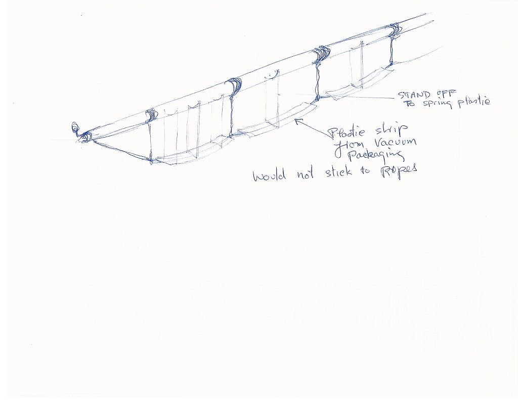
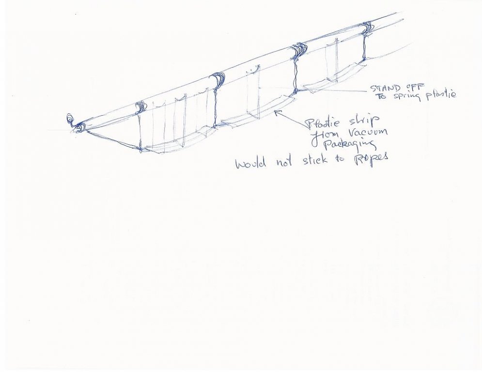
Hi Ed at risk of overworking the foot-rope issue of shape it occurred to me reading the comments about weights that a different approach might just prove to be useful. it involves shaping the rope by pushing gently on it with some clear vacuum packaging plastic. see the accompanying sketch I think it would be worth a trial on your jig. Michael
- 3,618 replies
-
- 12
-
-
- young america
- clipper
- (and 1 more)
-
Ah yes us folk who live on the outskirts of the civilized world eventually hear about these things, or stumble across them accidentally as I did. Michael
-
Lovely work, and wonderful to see your son working alongside. Michael
-
One of the issues with long lengths of naturally hanging rope, wire, or cable is that it tends to want to form naturally into a Catenary Arch which is the natural curve followed by anything hanging between two points. this curve is a result of gravity and the flexibility of the material hanging. To better understand this take a couple of blocks of wood with a pin in each place them about 6 inches apart and hang some model or jewellery chain between them, as the blocks are pushed closer together or pulled further apart the natural curve that occurs is a catenary arch. This is true for all curves hanging between two points. Therefore to get a clearer view of what the hanging foot rope would look like test the shape by using some small chain between the ends and hook the chain up at the various points, adjust the tension between the ends to get the required natural curves of the foot-ropes. Michael
- 3,618 replies
-
- 9
-
-
- young america
- clipper
- (and 1 more)
-
Fraid so John. Michael
-
One of the things that I do enjoy about following your work Ed, are the jigs and sequences that you use to accomplish this superb work. Michael
- 3,618 replies
-
- 7
-
-
- young america
- clipper
- (and 1 more)
-
I will be getting back to the ship by the end of this week. Michael
- 749 replies
-
- 10
-
-
- albertic
- ocean liner
- (and 2 more)
-
Very nice. Michael