HOLIDAY DONATION DRIVE - SUPPORT MSW - DO YOUR PART TO KEEP THIS GREAT FORUM GOING! (Only 13 donations so far - C'mon guys!)
×


Bob Fraser
-
Posts
291 -
Joined
-
Last visited
Content Type
Profiles
Forums
Gallery
Events
Everything posted by Bob Fraser
-
 Vitus, with the physical Longridge books you get some extra plans as inserts. These are 3 Underhill plans and a bulwarks plan by Longridge.
- 248 replies
-
- 1
-

-
- Cutty Sark
- Revell
- (and 2 more)
-
Hi Jerry On the older model the back wall of the engine room is fixed in place, on the new version the complete back wall and paddle assembly is removable. If you look at the new instructions, Section 4 pic 2 it shows extra slots in the deck, and Section 9 Pic 9 clearly shows the tabs on the bottom of the axle bearers. You'd need to unglue your back wall and axle bearers as one piece, and work out a way of making them fixed but removable. It looks like the switch and battery should be inside the second deck, with the upper deck removable to access? Welcome to the "King" club 😁 - please, consider a build log so we can follow along. Cheers, Bob
-
Looks nice and clean from here! A bit late, but painting the bolt heads can be done with a toothpick or a "dotting pen" (a steel ball headed implement) from a nail art tools set. Our middle lad uses one on his tank wheels to good effect.
- 132 replies
-
- 2
-
-
- King of the Mississippi
- Artesania Latina
- (and 1 more)
-
Looks good. Those stairs are the most difficult part of the build!
- 132 replies
-
- 1
-
-
- King of the Mississippi
- Artesania Latina
- (and 1 more)
-
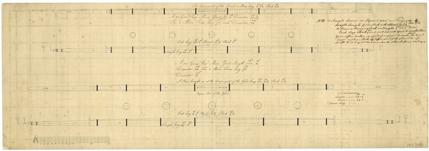
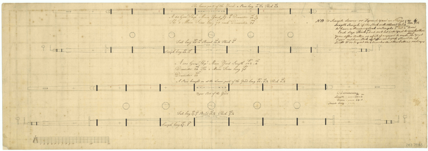
Is it something like this? Other examples are on the RMG collections with a search of Main Yard Hope this helps.
-
Had one of them on the wall in the bathroom as a kid early 60s! ⚡💀 😅
-
Hi Cleat. I didn't fit the spiral stairs at all but I would suggest sanding off the paint on the tops of the rails, and a light sand under the rail tops to help them stick. I'd check the other builds to see how they managed this issue, but personally I would fit the steps before cutting a filler piece so you can see the shape and size needed. Don't forget, unless you have spare wood there is very little scrap to spare with this kit. Looking ahead when you get to part 30 stop! Parts 88 I found are NOT all the same length as suggested due to the curve of the deck each can be 0.5 to 1.5mm different depending on the individual fit of the upper deck and whether or not you've planked the ceiling. They are also angled inwards which isn't very clear on the plans or instructions so you'd need to allow a 0.5mm for that too, but seperation distances using the big plan are good. I had to use calipers to get the right lengths.
- 132 replies
-
- 2
-
-
- King of the Mississippi
- Artesania Latina
- (and 1 more)
-
That's a good buy! The order is inside to outside and I believe standing to running rigging so that you're not trying to fit things like stays after shrouds or have other other ropes in the way. Stilltrying to learn this stuff myself. There are other rigging books but a free one on google books is Biddlecombe, The Art of Rigging 1848 gives an idea of the naval practices. Another book is Marquardt that deals only with 18th century rigging but is now, to me anyway, hugeley expensive, cheapest i found is Fleabay at £75 I have both Lees and Marquardt bought cheaply years ago before they became "much wanted" and shot up in price.
-
Hi Thomas. It looks like it doesn't it! Took me a while to find this as the newer instructions are diferent to mine. Are you using the motorising kit? Even if not don't glue the plate on just yet! The backplate is made up and held in place with elastic bands (page 77) to help with the positioning of the upper deck, uprights and fencing. It's not glued into place just yet because it needs to be removed complete a future stage more easily. Look ahead to page 228 section 34 in the instructions where it details the paddle making and attching process. There aren't any locating lugs for the backplate for a reason - the paddlearms go through the outside slots and a rubber band through the inside one on the left to attach to the motor. See pages 234 and 235. If you're not using the motor then the inner slot can be planked over.
-
Them's the pieces! Part No. 77. Assemble them into a square and then cut to size. Mine was 7 vertical and 6 across. Measure the inner linings of the hole to make sure of the size. You'll probably have to do a little sanding on the outer ones to get a good fit.
- 132 replies
-
- 2
-
-
- King of the Mississippi
- Artesania Latina
- (and 1 more)
-
The new style instructions and my old picture instructions are different to your piece! I'd hazard a guess that the pointy ends fit under the upper deck to either make your steps level or leave the deck as the last step. The picture instructions, pic 29 old instructions, don't show the pointy bit on the railings either, (although it is there on the part!) and the step fits below the deck level. Other modellers appear to have cut them off, but this image by @Warnerade appears to show, even though it's removed, that it should fit below the deck.
- 132 replies
-
- 2
-
-
- King of the Mississippi
- Artesania Latina
- (and 1 more)
-
Hi Cleat. The mis-aligned holes are for the anti-hogging posts (AL call them "Turnbuckles"). These should be visible on the side view plan of the model. They form an arc front to back that stops the ship from bending up or down in the middle and should be rigged with rods, not rope, to stop the bend in both directions. @Cathead thanks for explaining their use to me after my own head scratching moment, and his video at Catheads Presentation is a good watch. Couple of websites you might find interesting Steamboats.com and UWLAX Murphy Library photos
- 132 replies
-
- 2
-
-
- King of the Mississippi
- Artesania Latina
- (and 1 more)
-
Not sure of the actual size of these pieces (mine is still cellophane wrapped!) Would you be able to scrape out a recess, or will you be trying for a closer representation?
-
Looking good!. Just dug my old instructions out - it used to be a thin ply wall covered by 0.5mm thick walnut planking that splintered everywhere.
-
HI there. I'd like to follow along too. I've the older kit, partially completed on the shelf at the moment for about 18 months due to life! I do still have the printed papers if you need a help. Major differences are the photo-etch brass, the bow stairs to the upper level (changed from spiral to straight / spiral - much easier!) and the paddle axle has more spacing. There are several other builds completed on this site - just ask if you have questions everyone is very helpful! Edit. Just seen the pictorial instructions for this version, and they are much better than the original ones! Cheers, Bob
-
Bob - it's looking really nice so far - missing parts are sent (or not!) to try us. At least ME are sending them out.
- 146 replies
-
- 2
-
-
- Harriet Lane
- Model Shipways
- (and 1 more)
-
Hi Mike. These Sergal kits do have pretty limited instructions ( I have the President on hold), and they seem to have a penchant for misnaming / representing some models as real ships rather than a type. If you do a search above for "racehorse" in the titles only you'll find some completed models, and the Articles database here has good planking tutorials. This link shows plan details of the Racehorse 1757 and this the Granado 1742 that the model appears to be loosly based on. Whatever you do, have fun with the build and enjoy it. Cheers, Bob
-
Hi Tom. Have you seen Gil Middletons build of the Vic? And / or Longridges Nelsons Ships page 257/8 which goes into detail of how it is rigged and where the lines are run. I can post some info pics from the book if you wish. Cheers, Bob
-
These look really good - mine are a bit of a mess as I didn't think of drilling holes until too late 😪, 🤯. I just used a pin pusher, a tool I find is pretty useless when it come to pushing the supplied pins!
-
Wiki Commons HMS Diana 1794 takes you straight to them. 40 - 113 Mb in size
-
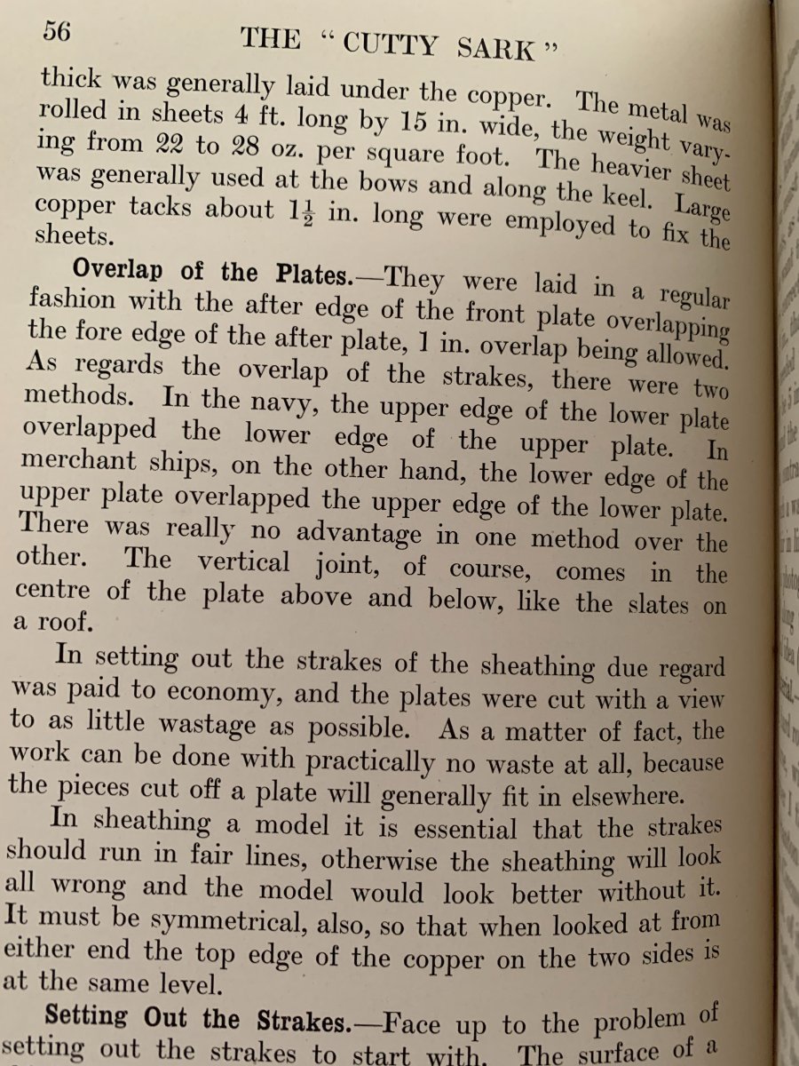
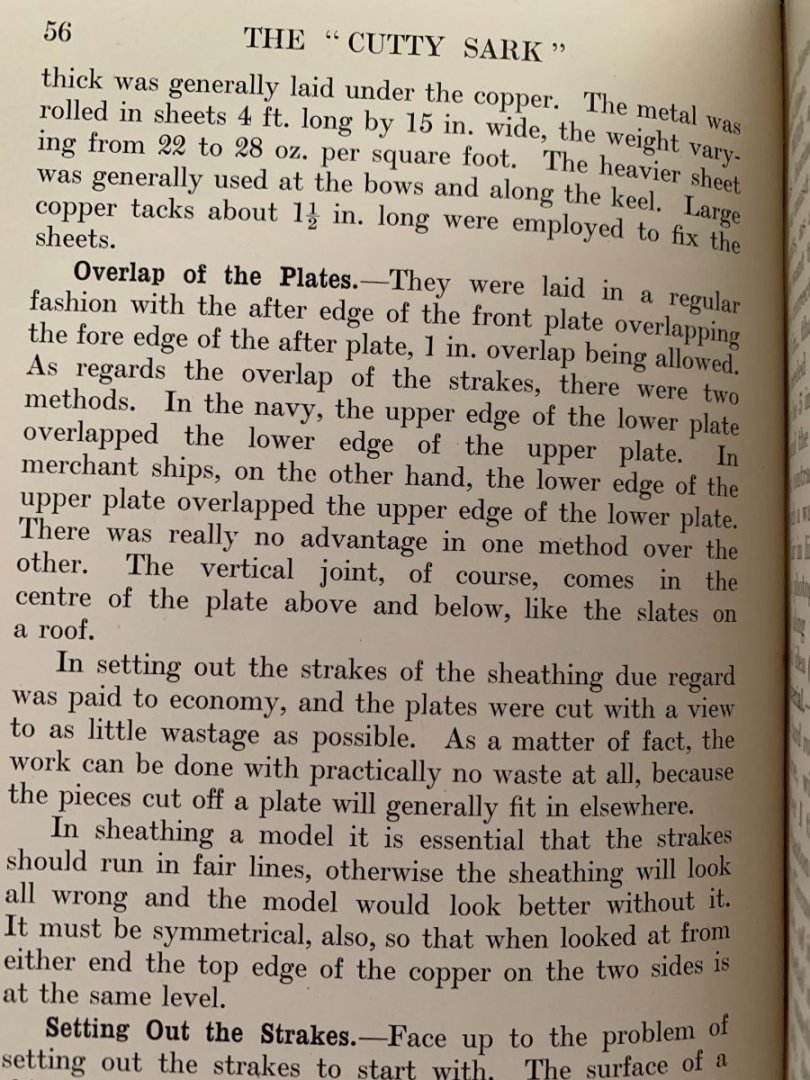
HI John Just managed to get to my copy of Longridges books, and "straight from the horses mouth" so to speak One source has said that these plates would be in reality about 1mm or just over thick at this size.
- 39 replies
-
- 2
-
-
- cutty sark
- sergal
- (and 1 more)
-
HI John Found this on fleabay CS Muntz Plate that is full width and 1/5th length. The blurb says width is 16" and full length would have been 48" max. This is Jock Willis very detailed specs for the CS Specs see item 58 for weights of yellow metal (Muntz) used. The home page of the above CuttySark has a photo of such a plate being applied to the hull close to the keel and rudder. Detail says the overlap should be 1" Hope this helps!
- 39 replies
-
- 2
-
-
- cutty sark
- sergal
- (and 1 more)
-
Hi Cleat Looking good! If you've done both sides of the doors you could skin them with some scrap planks. The doorways are quite deep compared to the doors themselves, so it would work. I've just used Danish Oil throughout on mine, it darkened the woods slightly. The pattern on the windows is made by scoring the plastic with a knife at 45 degrees left and right, and then wiping black paint into the lines. Not much is provided, but the thick plastic windows on some supermarket packaging are worth salvaging just in case. As these doors don't open the easiest way is to glue the plastic behind the opening, otherwise put some edging half way into the opening to create a frame to put the plastic into. There's nowhere to hang the doors either, so when it comes to fitting them they'll need a backing piece inside the building to fit them to.
- 132 replies
-
- 2
-
-
- King of the Mississippi
- Artesania Latina
- (and 1 more)
-
Hi Cleat. The dimensions given for the pieces are 1mm thick by 4mm wide x length. With the straight pieces glue them on with a 2mm overhang so it can be trimmed back to the door when solid, leaving you with the thin edging strip. For the curve, it turns out I cheated and have an inner straight edge and used the door curve to give the upper profile. To cover the open tab slot I chose to edge the buildings with a skirting. As a bonus this covers any gaps between the building and the deck. Your planking looks really good! To get the dark lines people use a soft pencil or felt pen along the edge. Beware of the felt pen as the wood could soak it into the grain. Cheers for now, Bob
- 132 replies
-
- 2
-
-
- King of the Mississippi
- Artesania Latina
- (and 1 more)
-
Don't know how I missed your build! Good idea! Keep as much of the offcuts as possible as they will come in useful later! 🙂 @Cathead is very much an authority on these ships, and has helped me enormously with mine (still ongoing, and will get a restart in a few weeks!) As @bobandlucy said, consult the large plans for placements, and measure your own build before cutting to ALs lengths, especially for the uprights, as I found they can be out by up to 1.5mm. (Fortunately before wasting too much wood, but the cuts fitted in elsewhere thankfully) Keep up the good work, Bob
- 132 replies
-
- 2
-
-
- King of the Mississippi
- Artesania Latina
- (and 1 more)