HOLIDAY DONATION DRIVE - SUPPORT MSW - DO YOUR PART TO KEEP THIS GREAT FORUM GOING! (Only 24 donations so far out of 49,000 members - C'mon guys!)
×


tkay11
-
Posts
1,827 -
Joined
-
Last visited
Content Type
Profiles
Forums
Gallery
Events
Everything posted by tkay11
-
 Thanks, Jörgen. Yes, it's the admiralty water based red ochre. Still a left over from my Sherbourne! Tony
 -
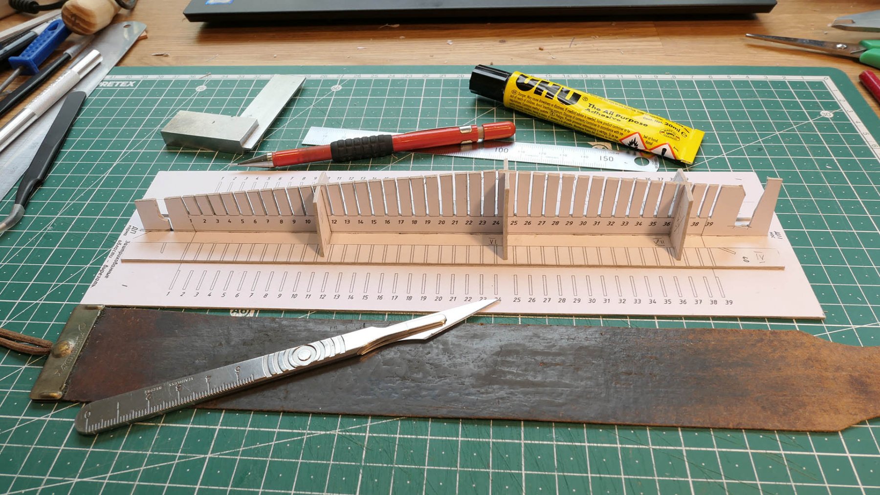
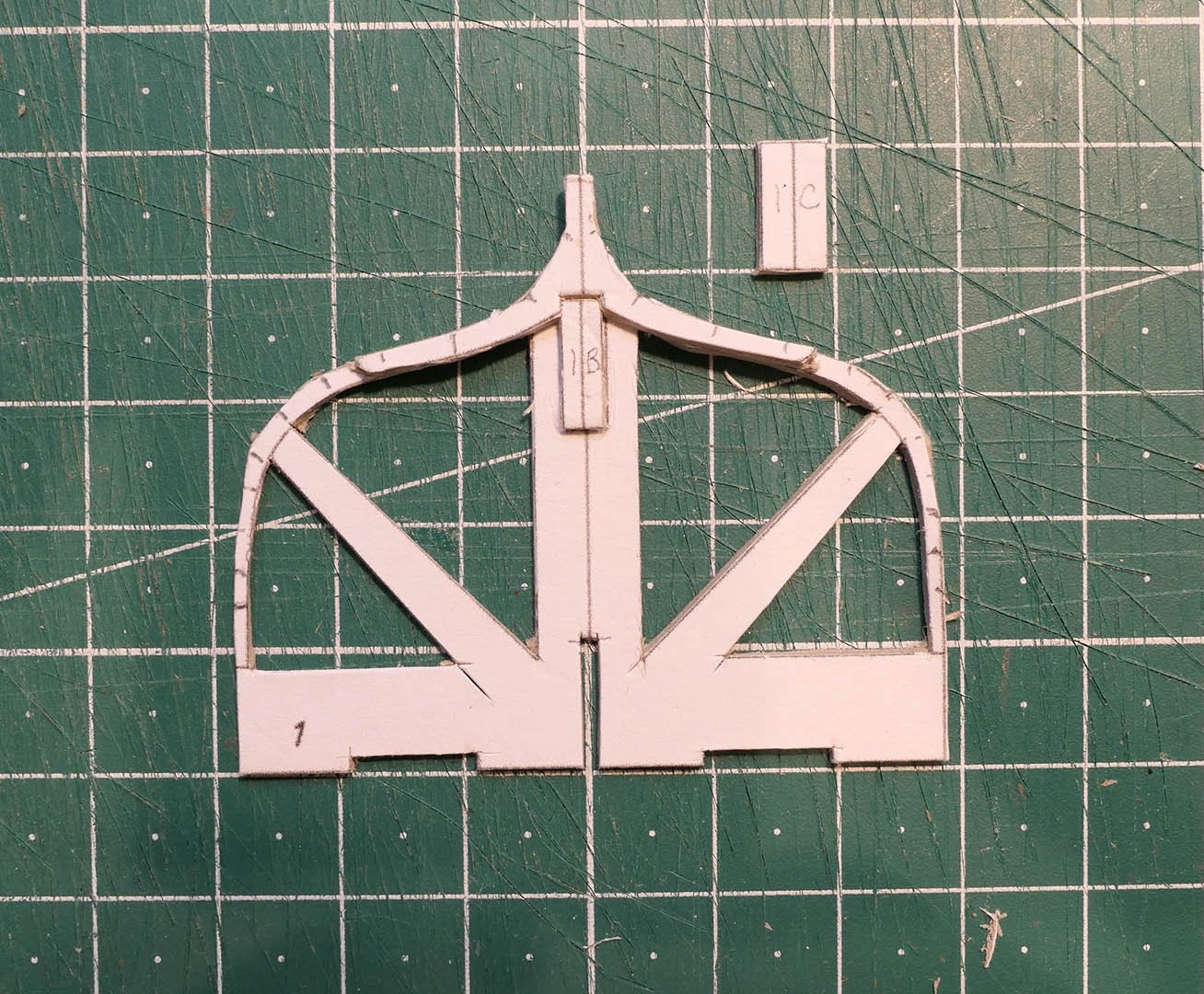
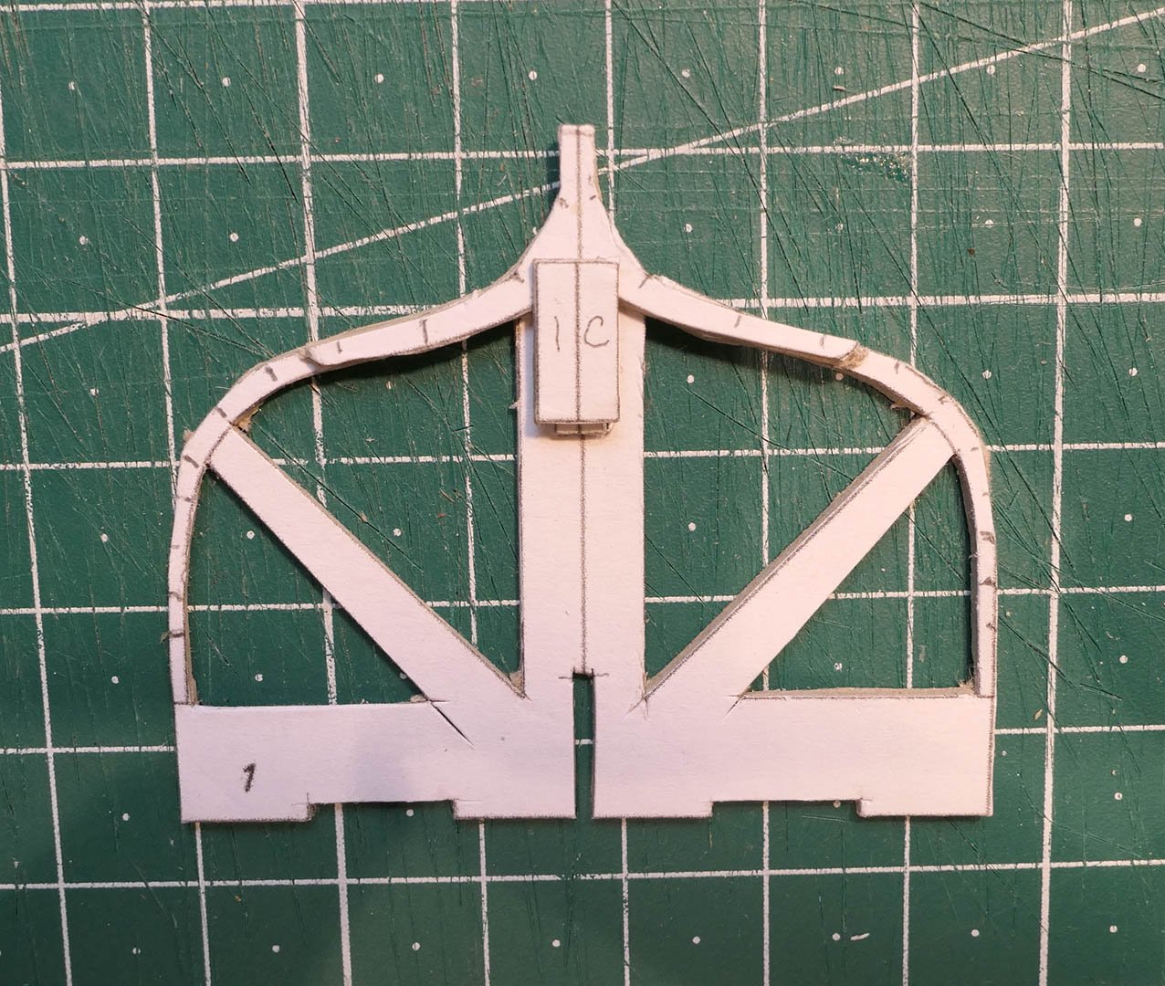
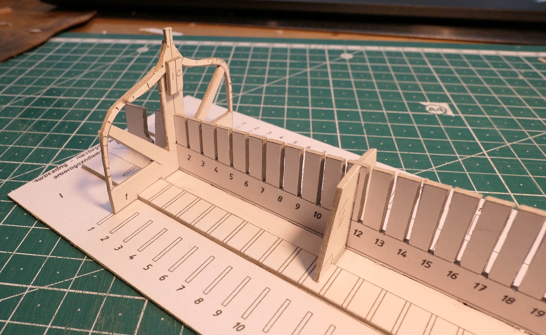
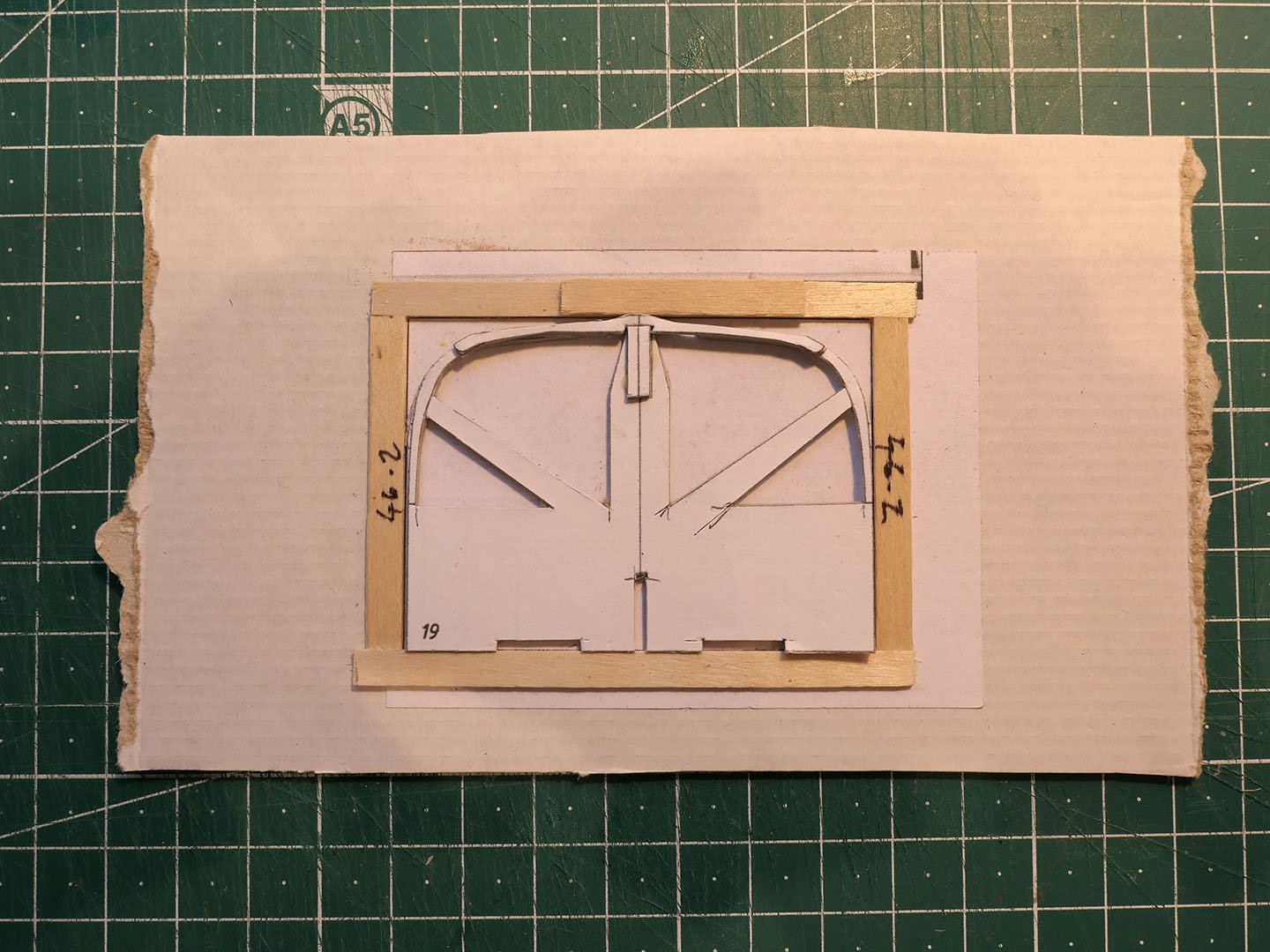
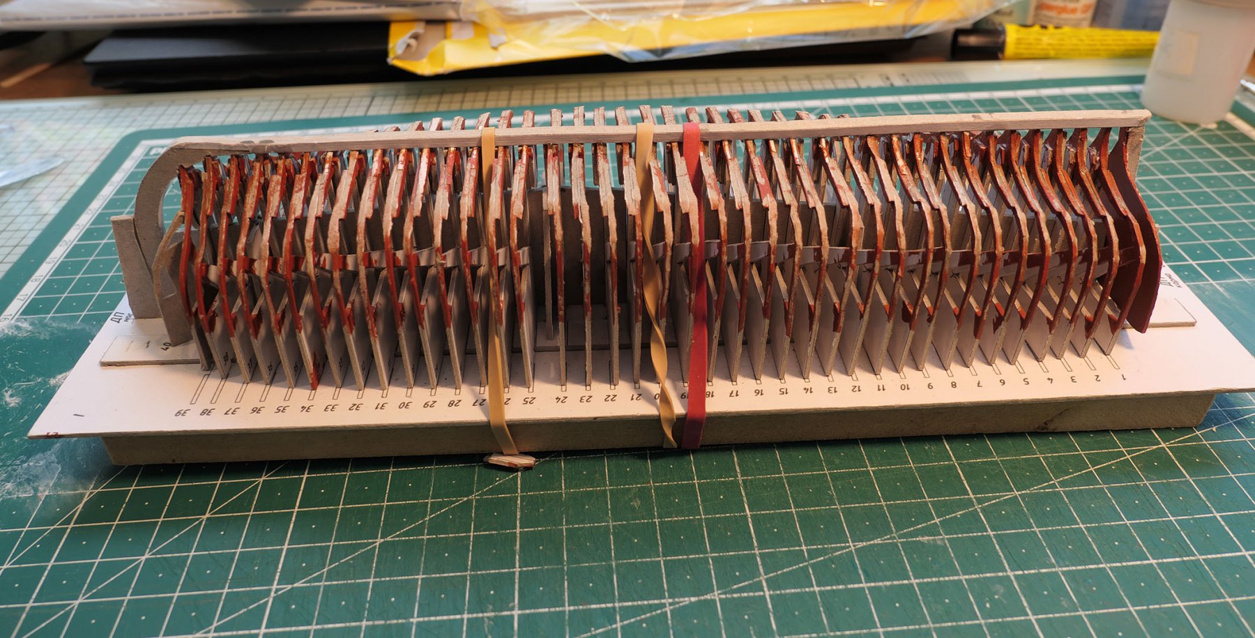
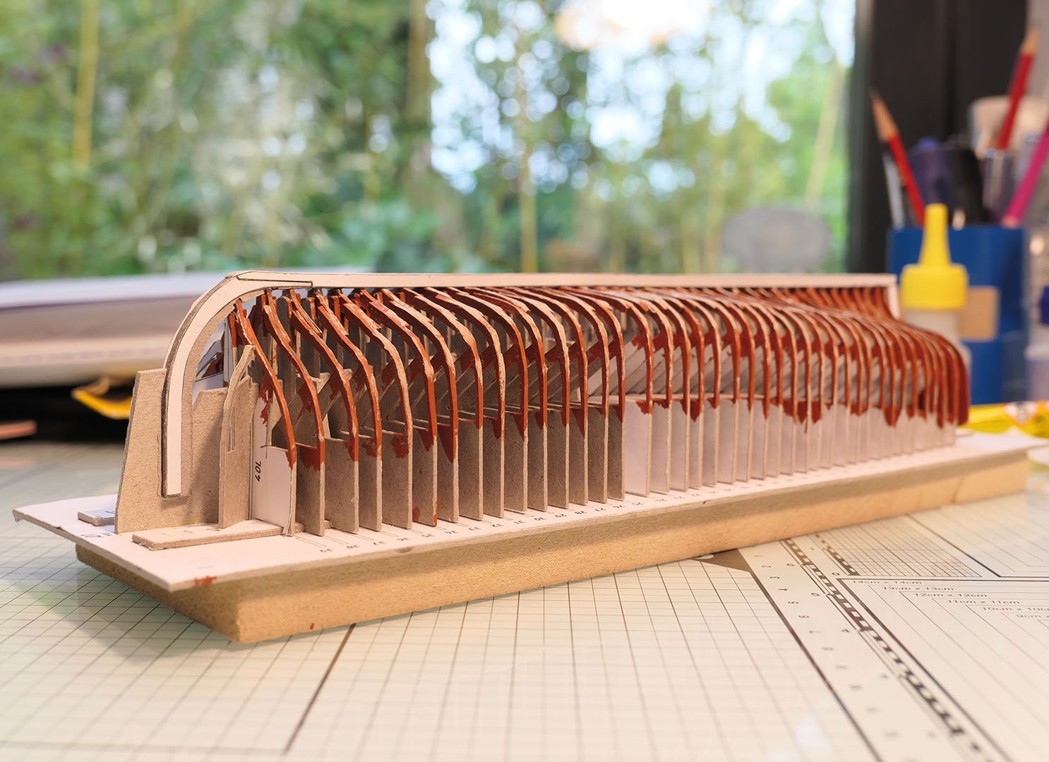
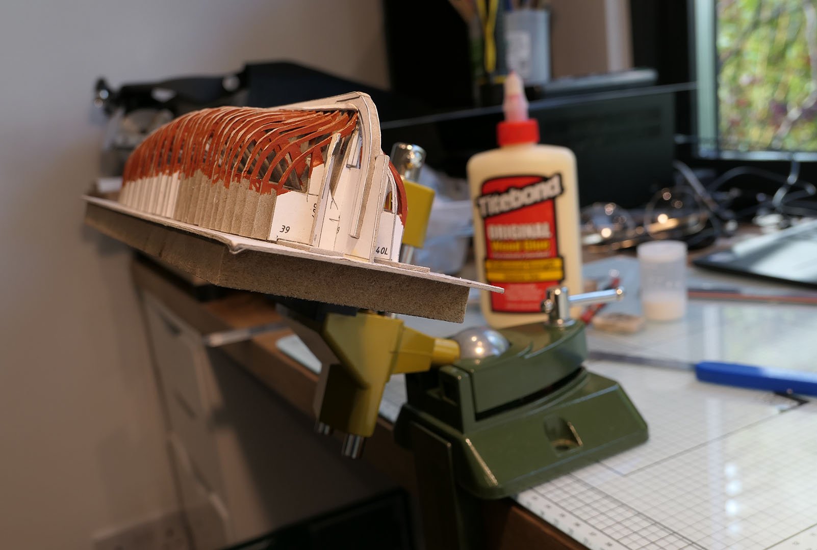
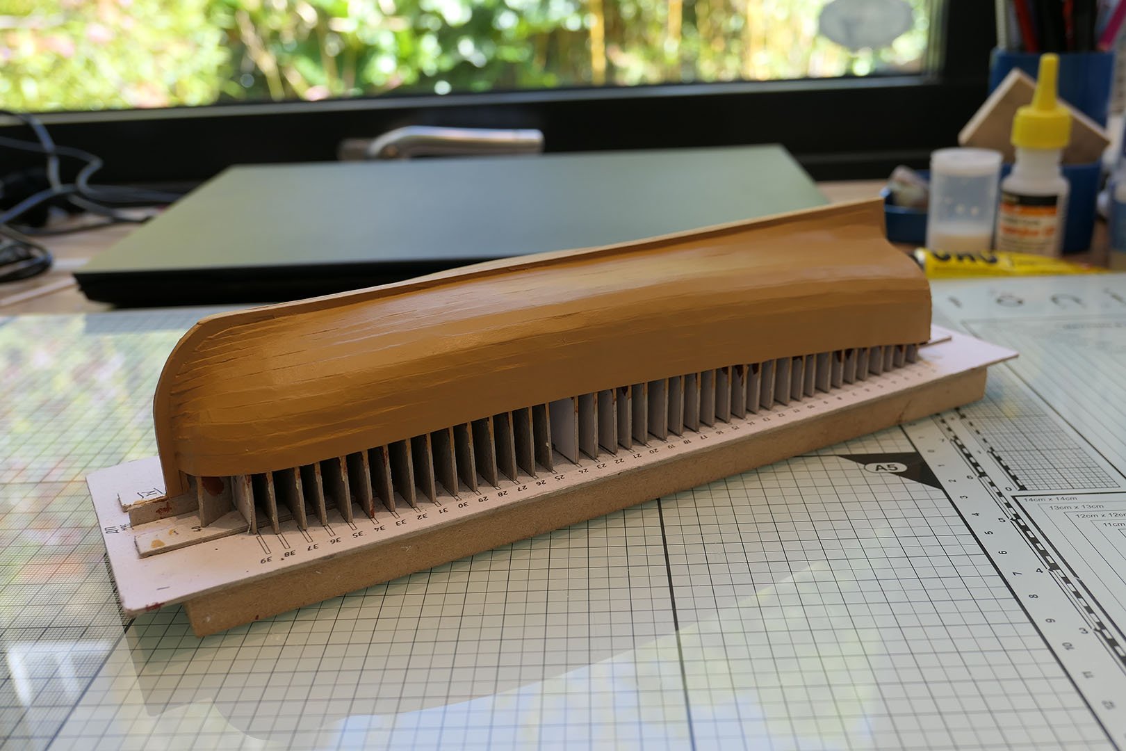
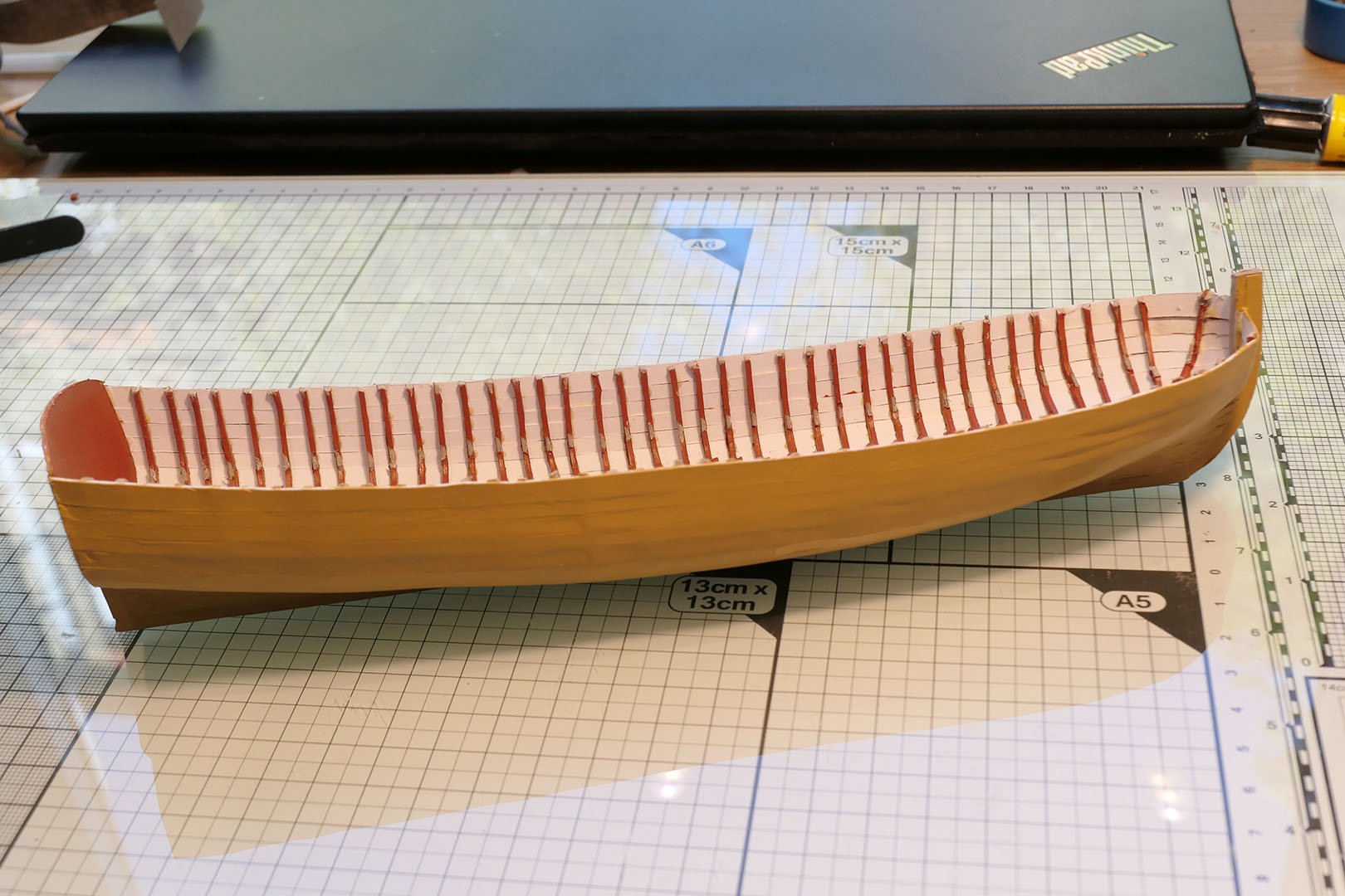
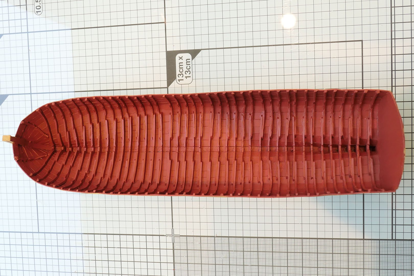
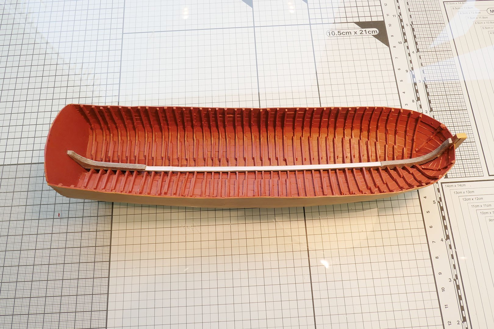
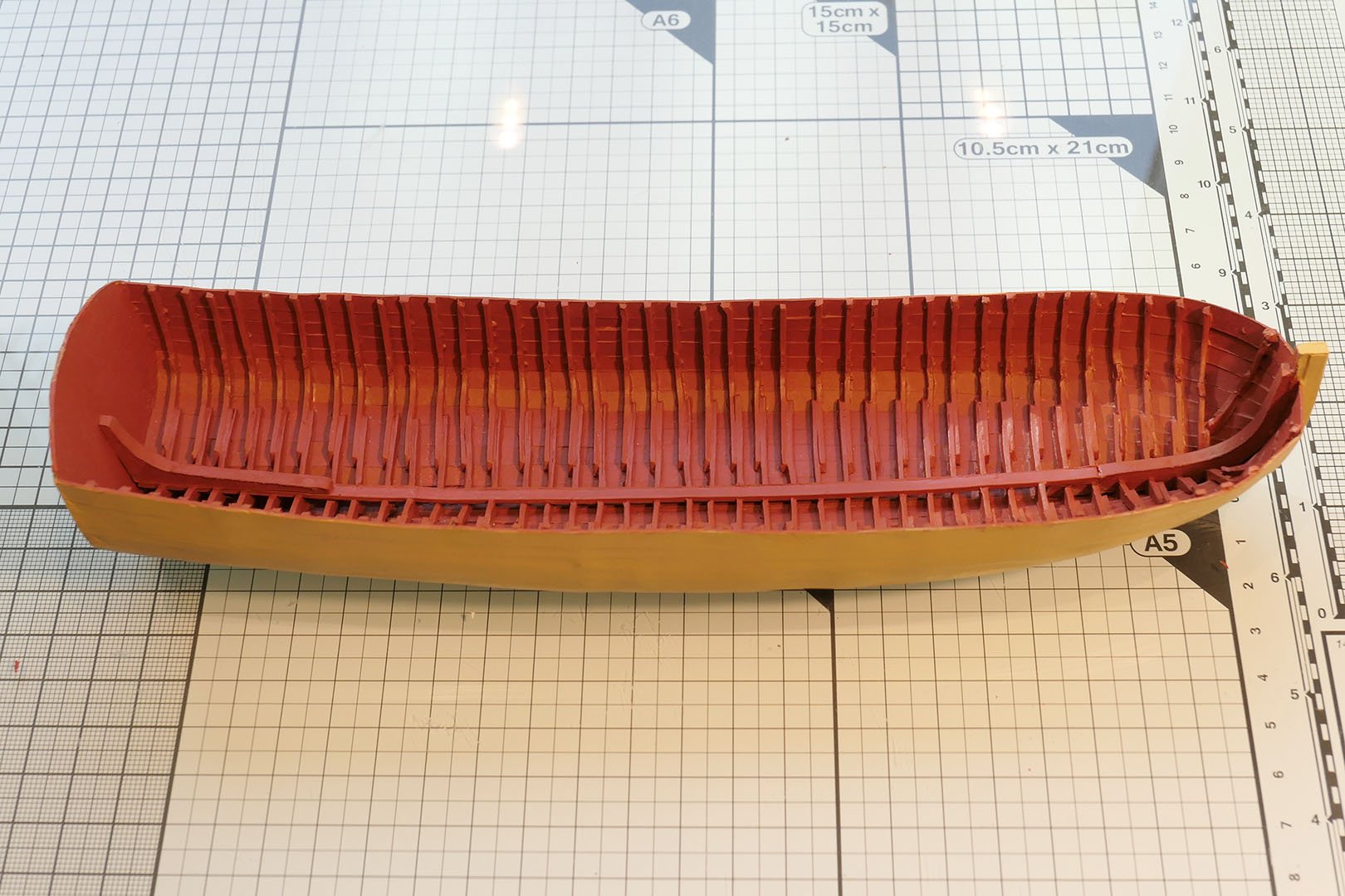
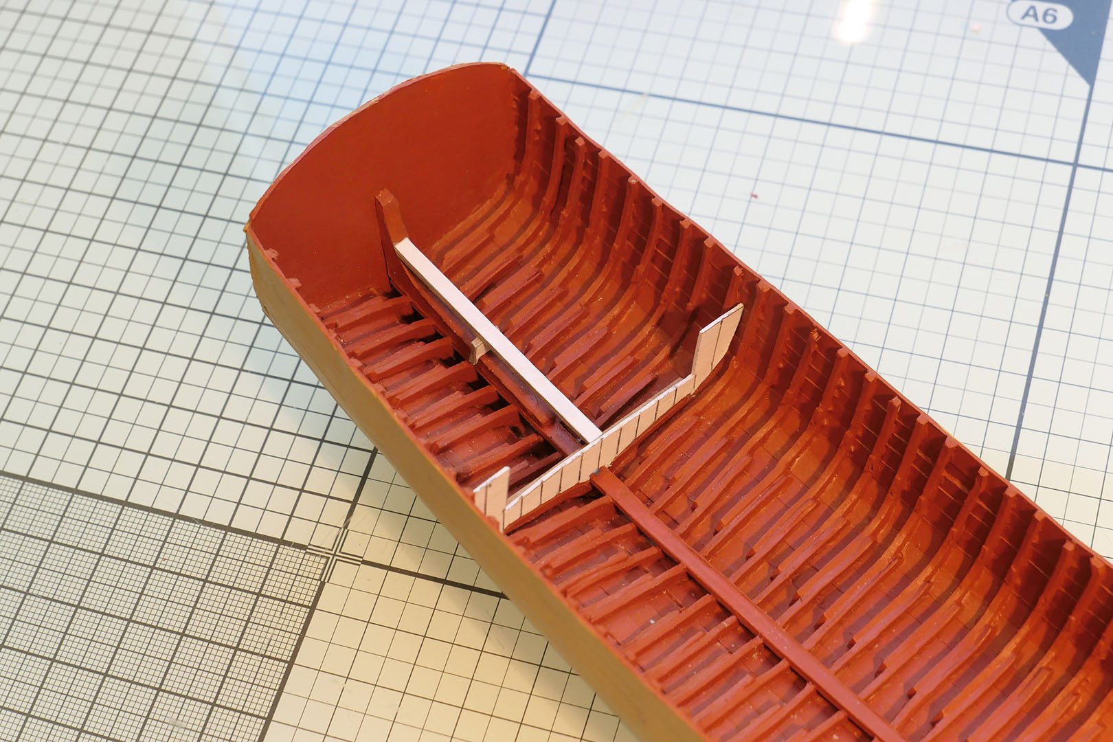
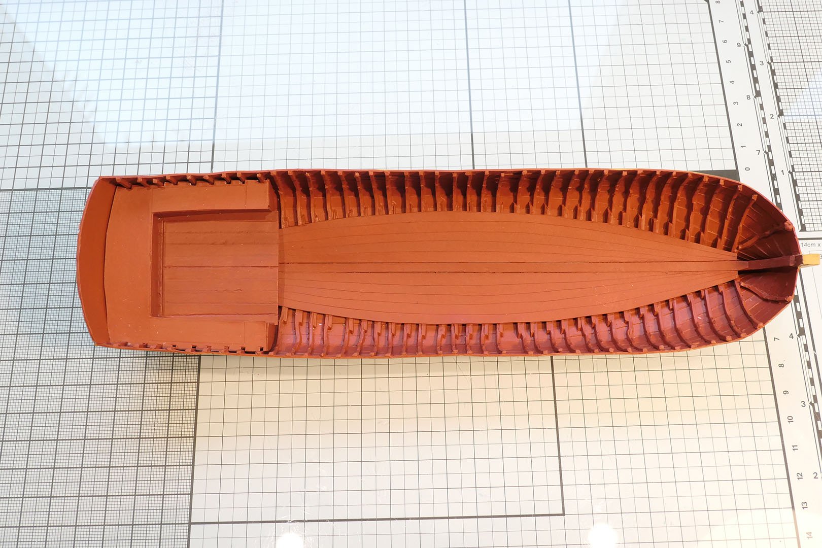
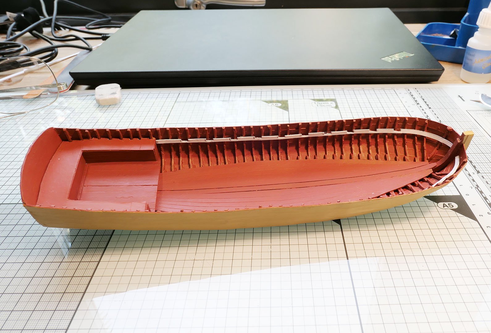
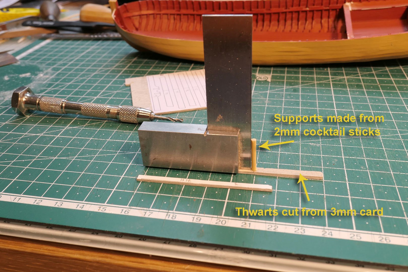
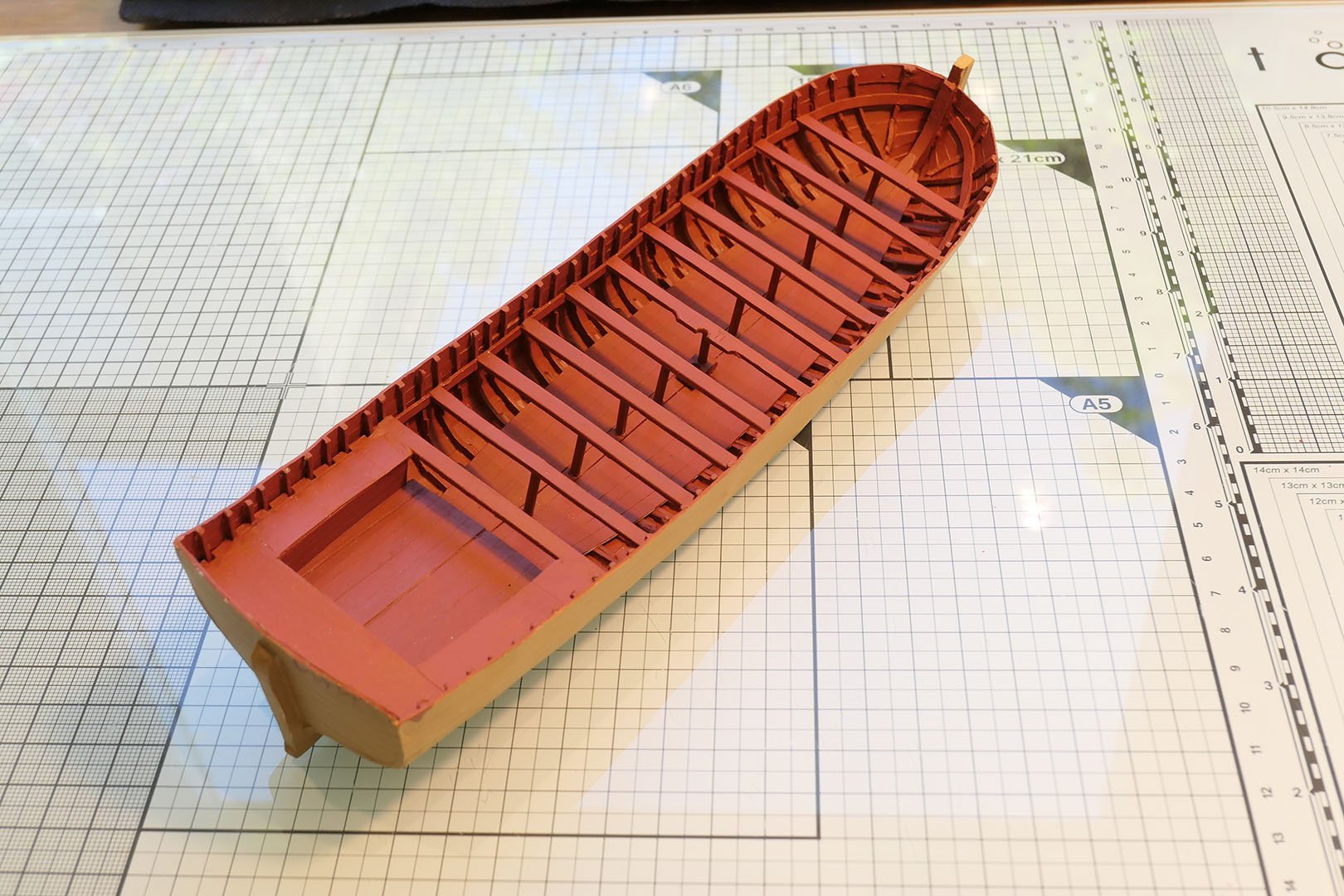
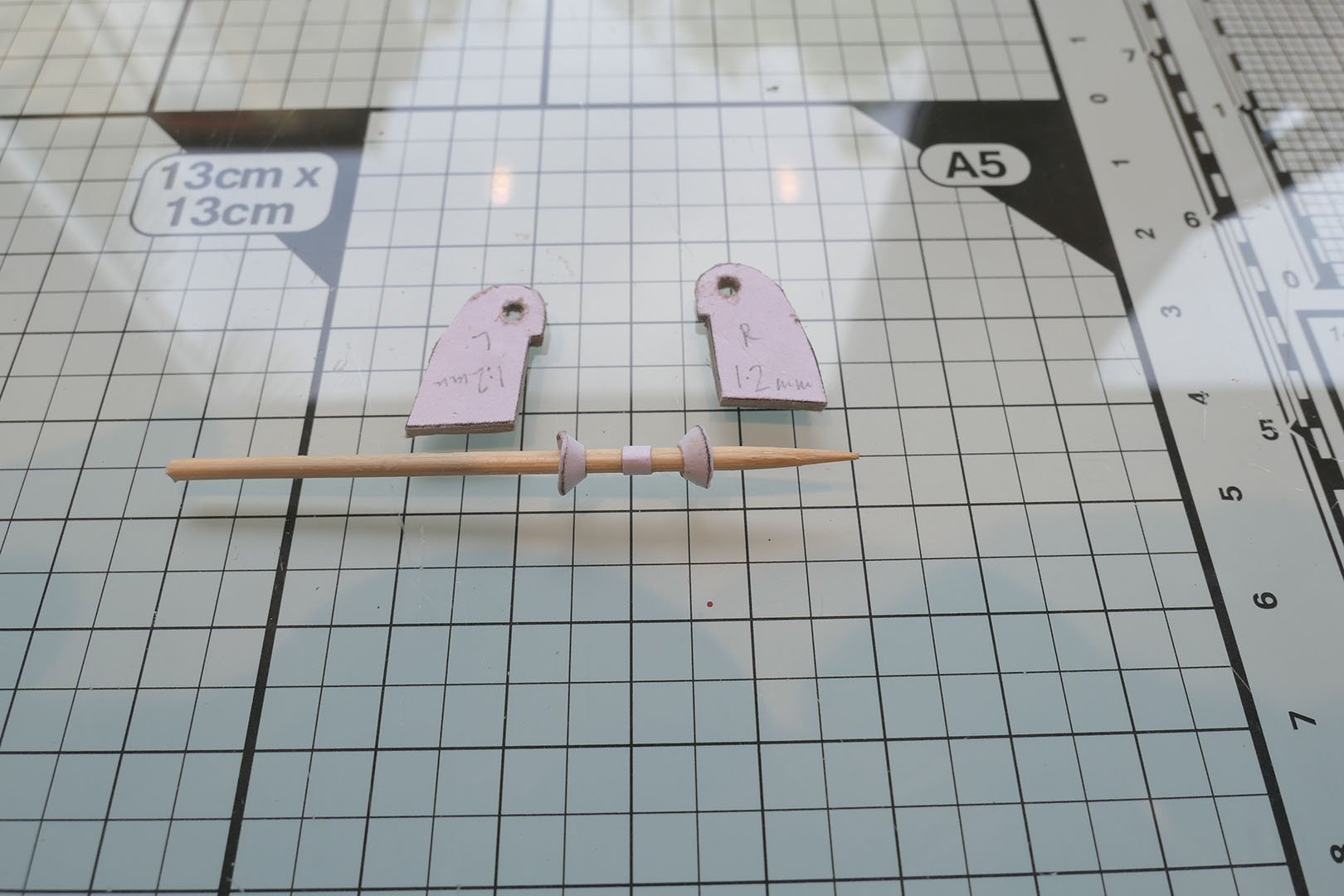
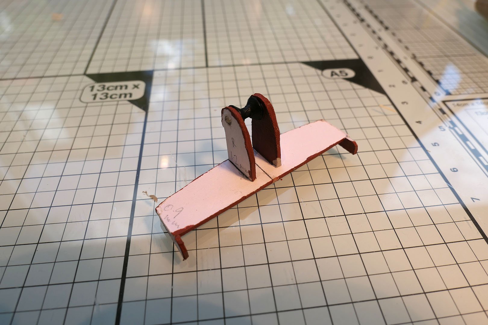
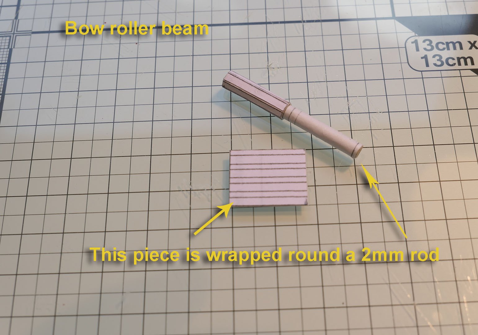
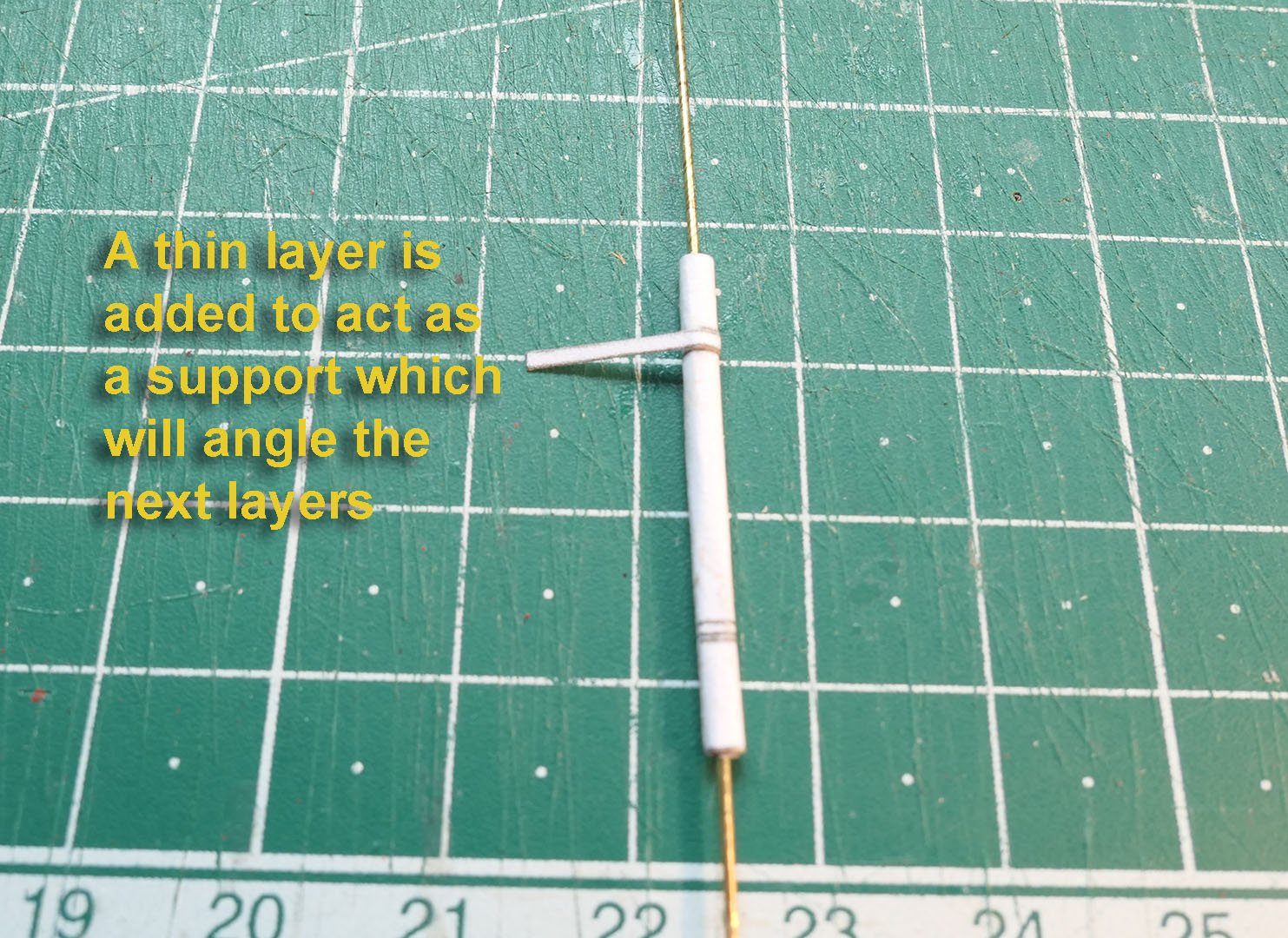
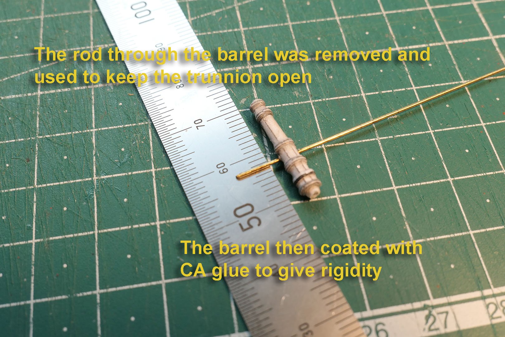
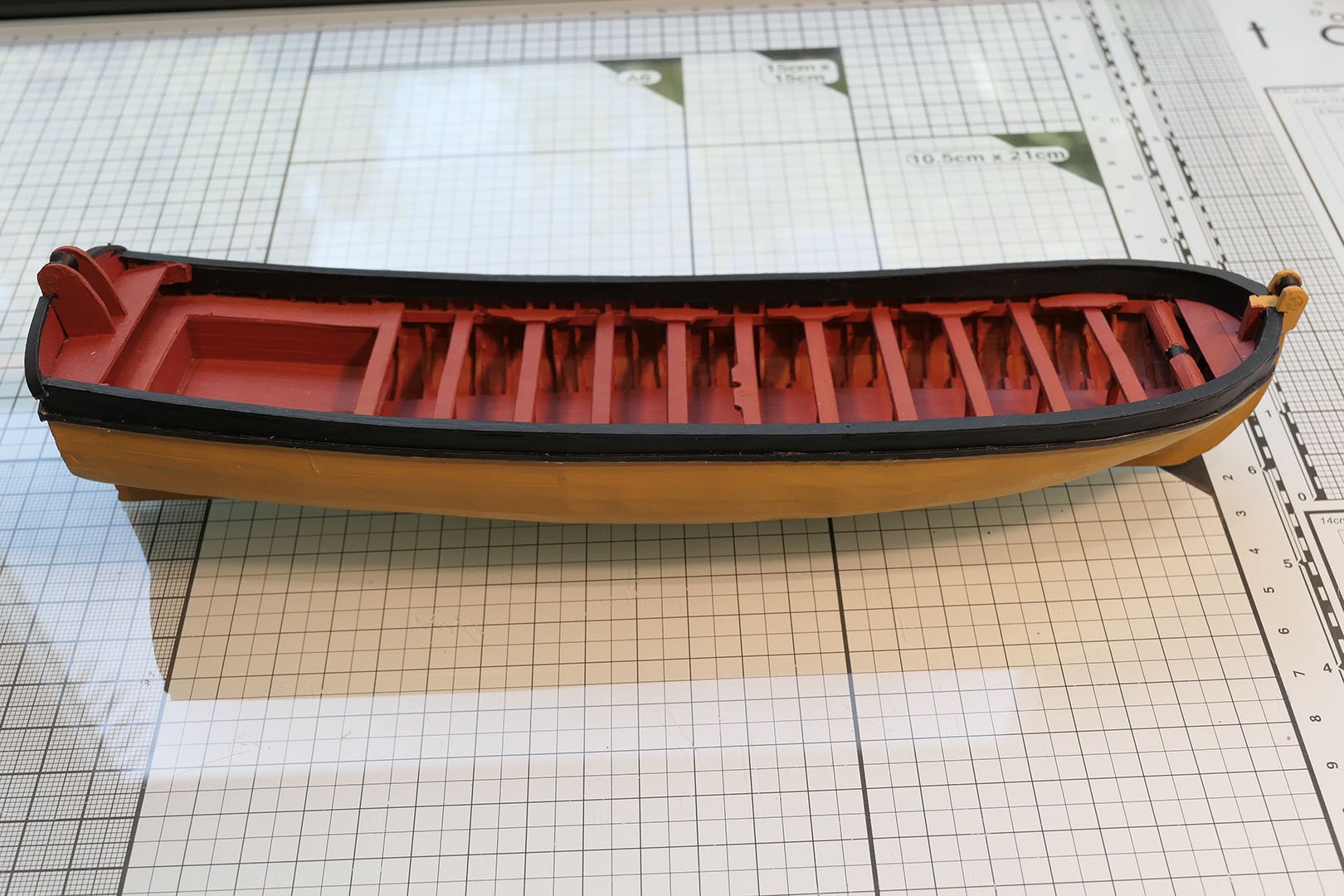
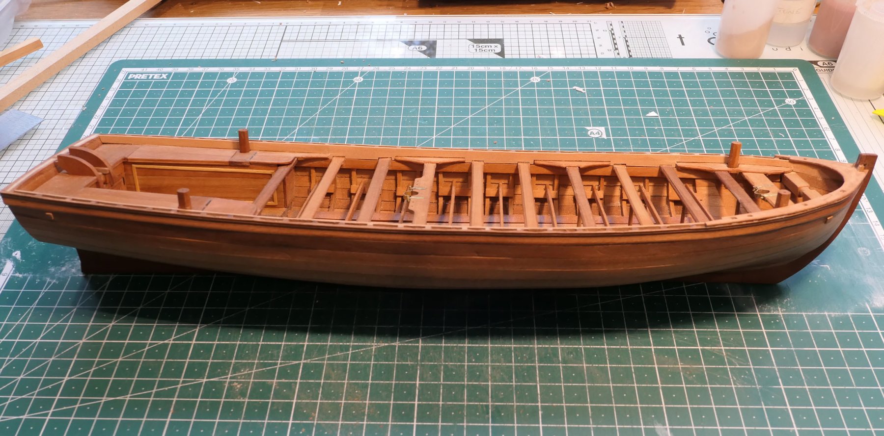
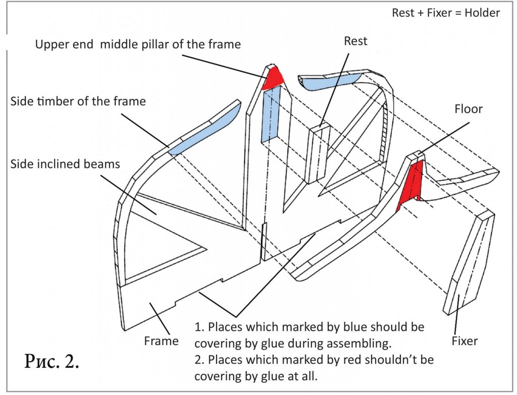
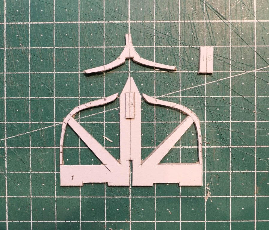
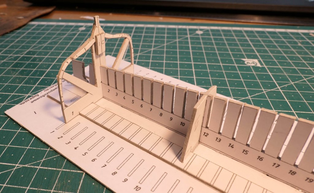
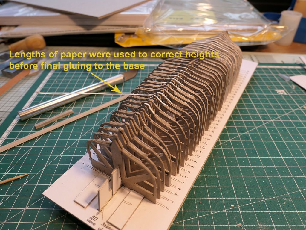
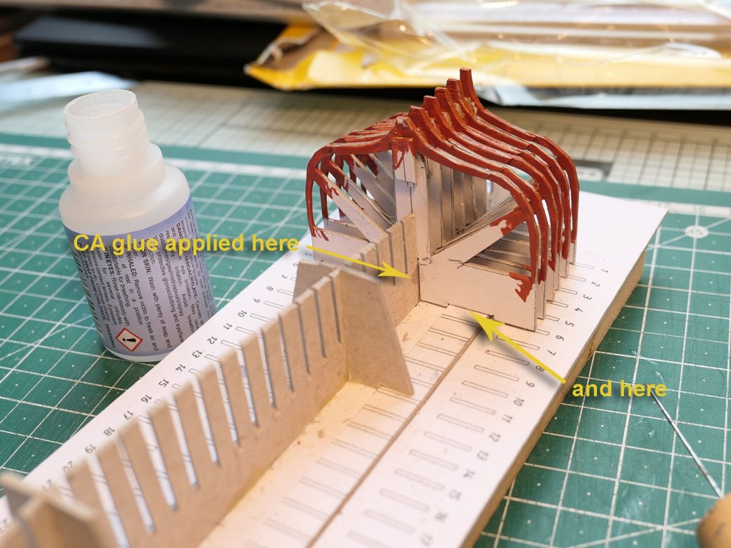
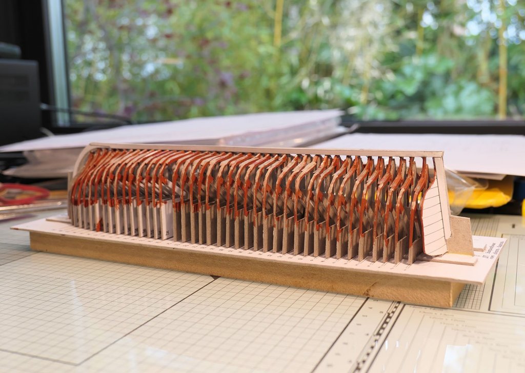
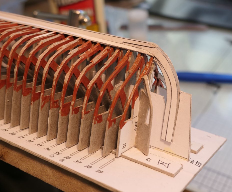
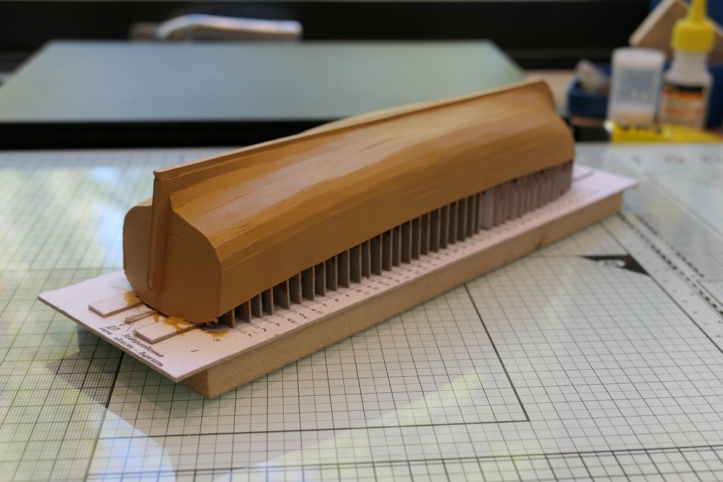
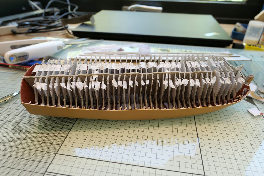
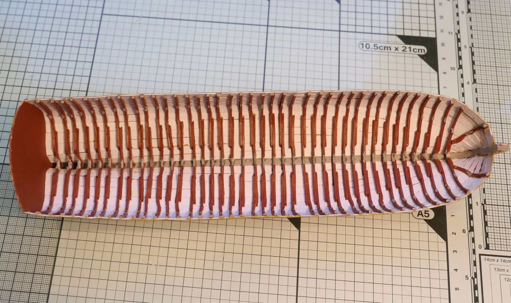
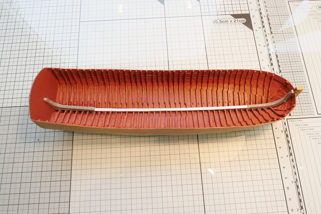
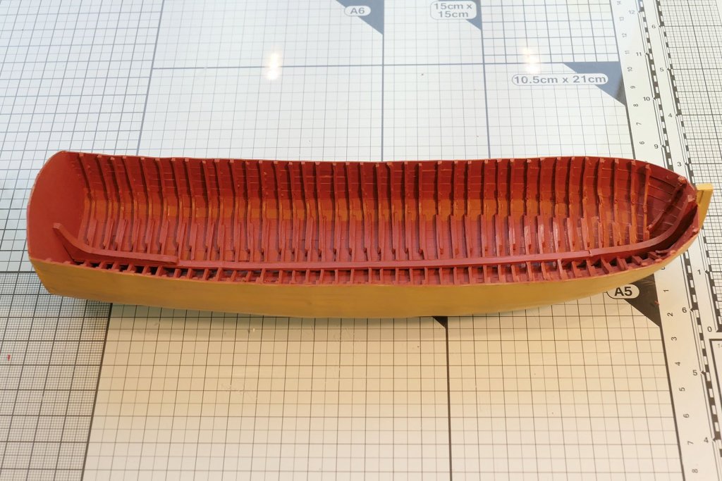
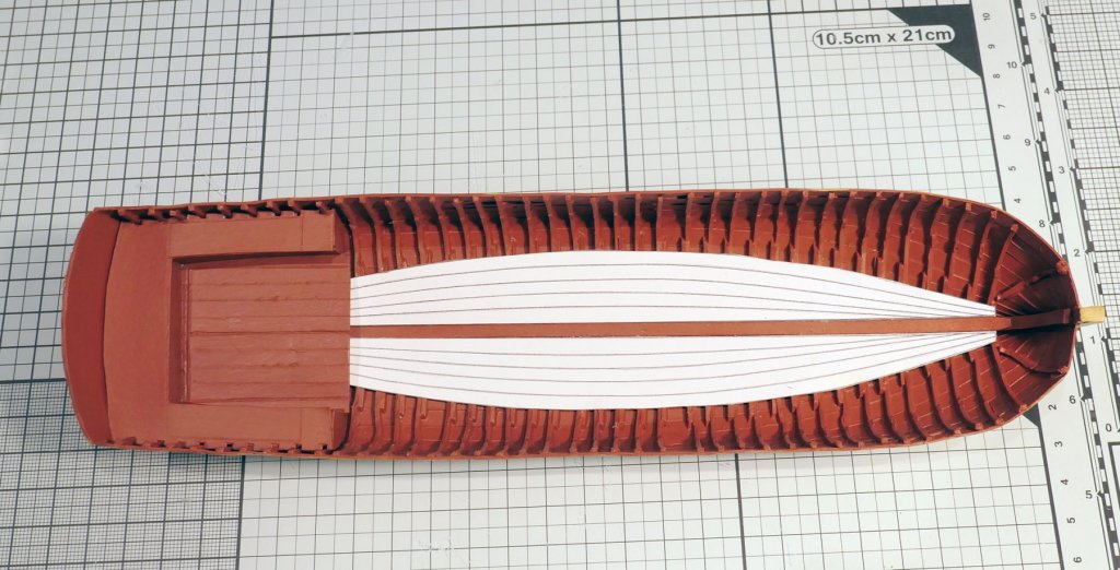
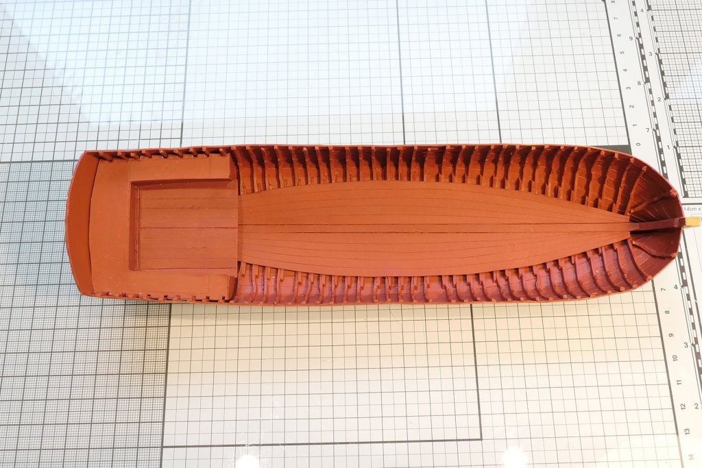
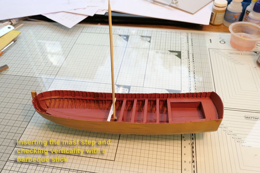
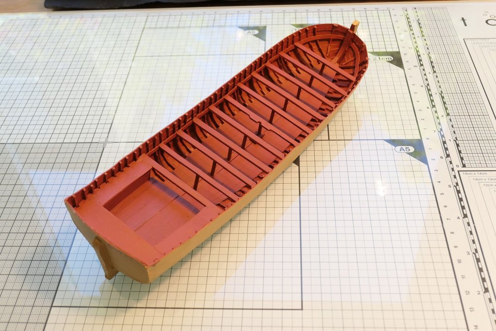
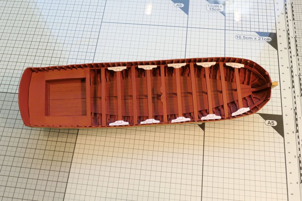
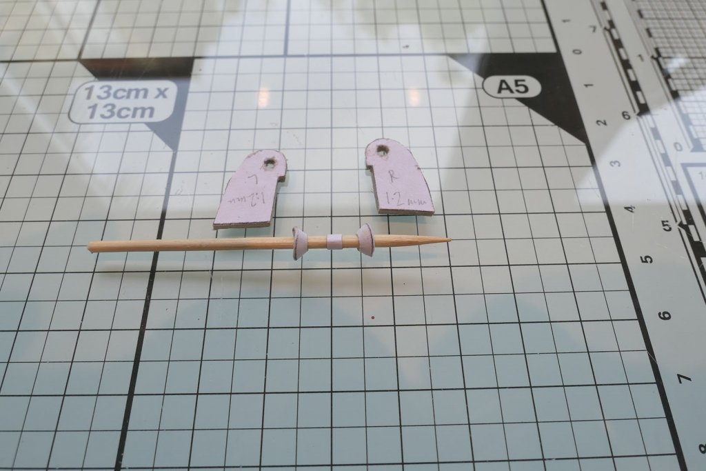
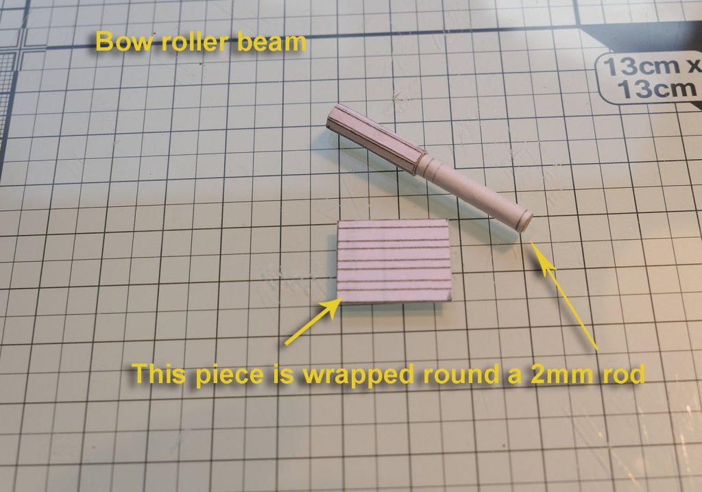
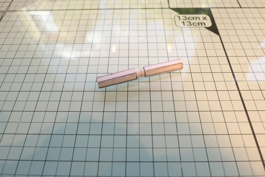
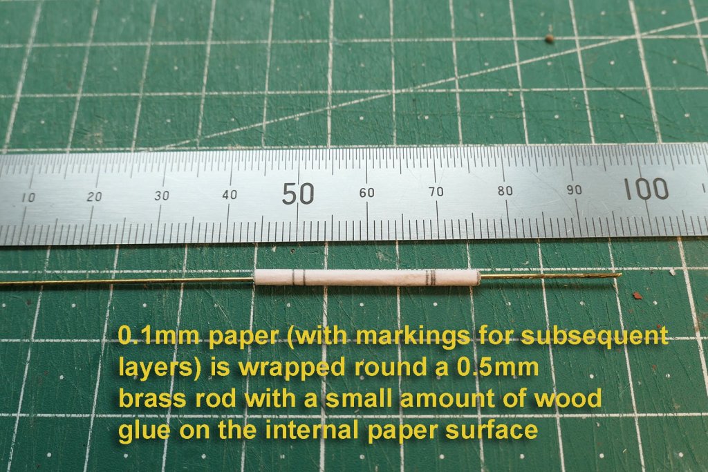
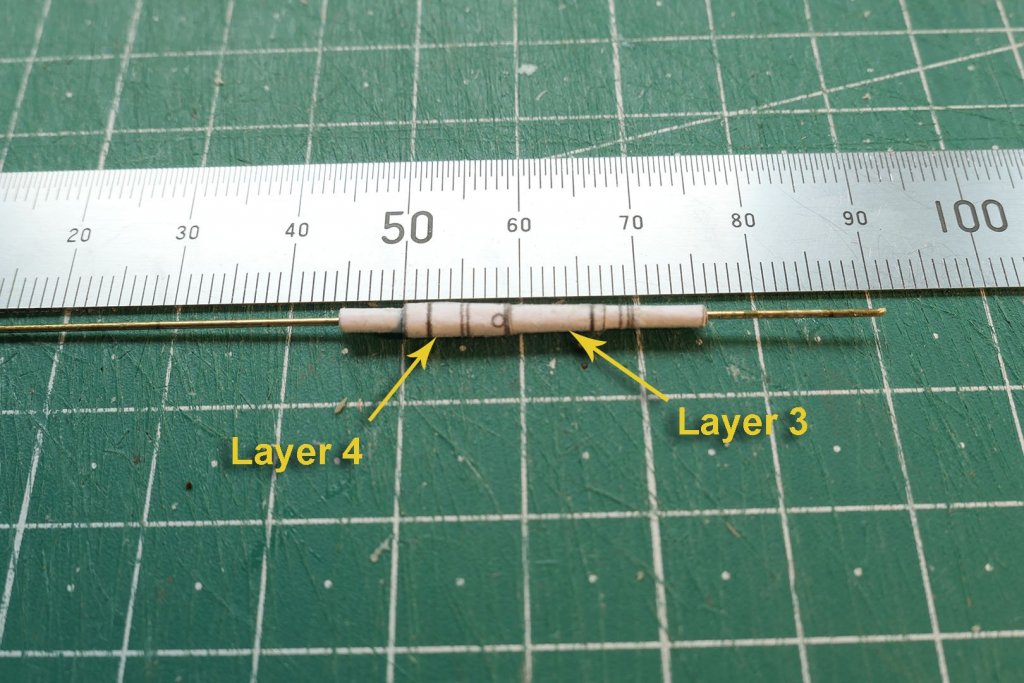
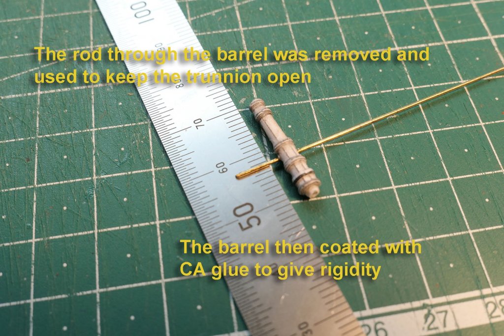
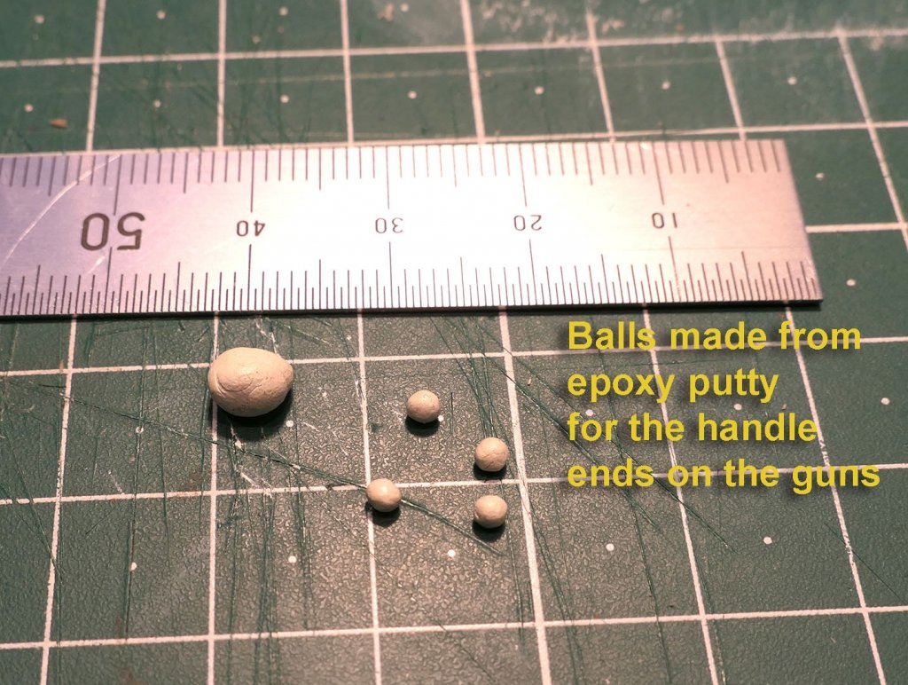
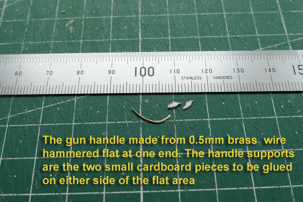
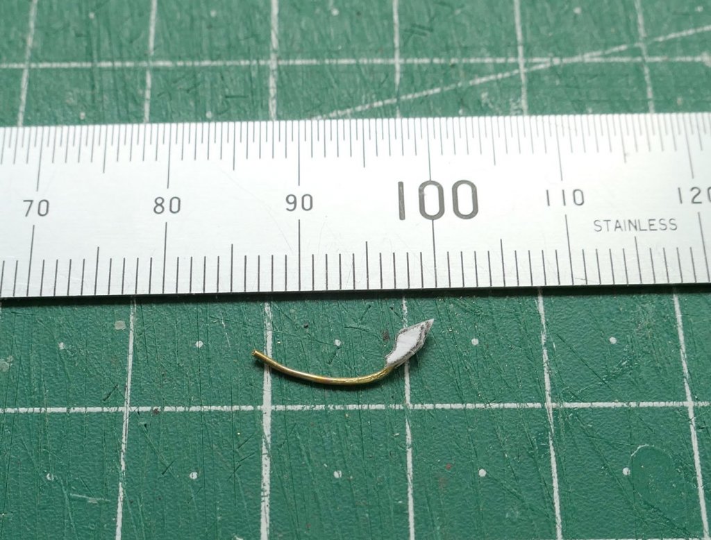
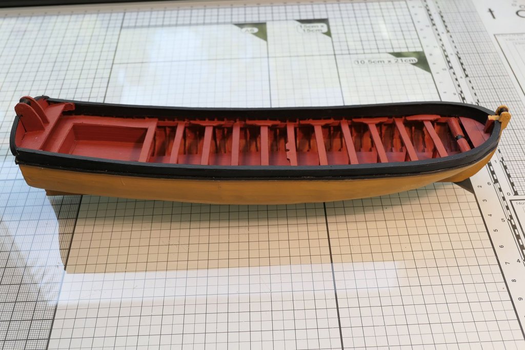
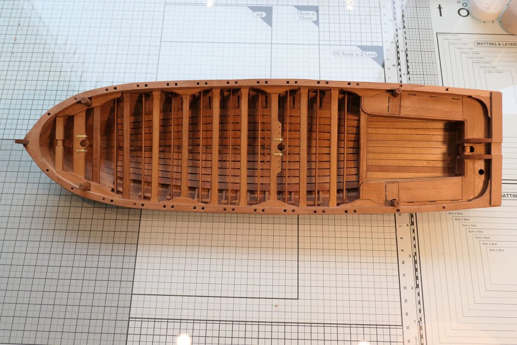
I bought this kit after seeing completed builds on this and other sites. It is a model designed by Daniel Dayn Vishnevsky-Karlskhagen and I was intrigued to see how a longboat with its small frames could be built from card. It uses the same principle as the wood kits for longboats: frames supported by an internal plate which is removed after the external planking has been applied to the frames. The kit is low cost (I spent about €25 which included postage from Russia to the UK) and has excellent instructions. The only problem is that the instructions and guide are all in Russian (albeit with very good and useful illustrations), so I had to work hard using a variety of sources to translate it all into English. See my post on Russian translation and the resources used at and previously in my Chaloupe Armée build. For those who buy the kit I will be very willing to send them the translations of the instructions with the parts list. I have done the translations as a table with the original Russian in the left column and English in the right-hand column. I also have made a table or dictionary of Russian nautical terms used in the guide which goes with the parts list. I think you can only buy the kit from the author, whose email address is bureau.k68@gmail.com. You can see his full build of the original on the Russian forum at http://only-paper.ru/forum/85-12867-1, and you can see his discussion about it (in English) on the papermodelers forum at http://www.papermodelers.com/forum/ships-watercraft/27125-french-longboat-xviii-cen-most-large-pinnace-tree-masts-sails.html?highlight=planking . Because my interest was mainly in the method of construction, but also because I was prevented from continuing with my build of the Chaloupe by recuperation from surgery, I only built this model as far as completion of the basic boat without any masts or additions such as anchors and cleats. My main purpose in providing this Review/Log is to bring the attention of a really interesting kit to others on this forum who are proficient in card modelling or who just wish to probe it (as I did). I would rate it as fairly tricky but very rewarding. What’s in the kit? In addition to the guide and parts list, the parts themselves are printed on standard A4 photocopy paper. There are several sheets of 0.3mm card which can be multiplied to provide various thicknesses. The list of parts also details how thick each part should be. An interesting aspect of this kit is that the card comes in three colours: white, yellow ochre and red ochre. This is to allow you to make the model with a minimum of painting. A really nice feature of the kit is that plans are also provided for you to make all the masts, yards and fittings as well as accoutrements such as barrels, buckets, cleats, hooks, belaying pins and oars. A full rigging and sail plan is included, with directions for the varying rope thicknesses. Finally, the author has a practicum with colour photos which he will send you (in Russian). The base The first thing to make was the base. This is really sturdy, and, as with all the pieces, requires accurate cutting out so that the frames, when inserted, fit exactly. You’ll note in the photo the Swann Morton scalpel with a no 26 blade I use which I keep sharp by stropping after every few cuts. You can get the idea of the frame assembly with the following diagram: It is clear that you have to be very careful with where you place the glue if you want to remove the shell from the assembly later. But you can see that it does replicate very neatly the framing structure of the boat with floors and futtocks. You can see the assembly sequence in the photos below. The guide points to the fact that all but three of the 40 frames have the same height, so it is important to have a method of making sure that the height is correct. I built a small jig to build most of the frames, but later on just used a slide rule to check the heights. Despite all this my measurements were frequently incorrect and I had to adjust several frames by filing or gluing on various thicknesses of 0.1mm paper. Because the frames were made from grey/brown card, the instruction was to paint them with red ochre. This I did, but regretted because (a) I painted it on too thickly and (b) later on it interfered with the gluing. You can also see how the paint covered the holding frame – which I then had to separate from the floor with a scalpel in order to ensure I could remove the frames from the mould. Actually, after finishing the entire 40 frames, I was so dissatisfied that I made the model again, base and all, to this stage again, but being more careful with glue and paint. I don’t have photos of the second frame and mould, so you’ll have to make do with the photos of the first attempt! Stem, keel and stern timbers were then cut from 3mm card, glued and the assembly held in place with rubber bands. Planking I then laid the planks. I could have used the coloured card supplied in the kit, but I elected to use my own card which I then painted with yellow ochre. The spiled planks were beautifully accurate as printed, so I did not have to make any further adjustments when cutting from the plans. As you see, the big problem for me was laying the planks so that they would be completely flat. Mine turned out in a rather wavy fashion! Once the planking is complete, the shell with its frames can be cut from the mould. First there’s the rough cut using curved scissors to cut around the edges at the level of the rubbing strake and then to cut the areas attached to the base floor. The frame supports can now be cut away. Because I had used my own card, I had to paint the interior with red ochre. Finishing the hull The keelson, stemson and sternson are then put in place. The counter and timbers for the cuddy can now be added. With the cuddy finished, the main floorboards can be inserted. The thwart stringers are placed. The thwarts were made from 3mm card, and the supports made from 2mm cocktail sticks. The mainmast step was made from wood, using the plan in the guide. Now the thwart knees. The davit timbers and their roller are now constructed and assembled. The front davit with its roller were made in an identical way. The main remaining piece of the hull was the roller beam at the front. Swivel Guns Having done the main hull (without the swivel gun mounts, cleats, mast straps, belaying pins etc.) I thought that even though I wouldn’t arm the boat I would still see how cannon were made with paper alone. The instructions in this regard are excellent. I started with a simple roll of paper, marked with the positions for the subsequent layers of paper. Final result So, at its current stage, the model looks like this: In comparison with my ongoing 1:36 build of the Chaloupe Armée: I won’t be going any further with this build as from now on I will concentrate on finishing my build of the Chaloupe Armée. It is just possible that at some future date I will continue, but don’t hold your breath! The purpose of this review/log was mainly to bring the potential of this very nice model to the forum, and especially those who wish to explore card modelling – which, as you can see, offers up its own delights, techniques, thought processes and problems. Tony


-
Thanks, Carl, G.L. and Dirk as well as for all the 'likes'. Yes, I am indeed walking, talking, joking as before. Surgery has advanced dramatically over the past decades, and procedures are more and more like a change of tyres in the pits with great team work between the specialities, then off and out again. The NHS (for urgent cases anyway) is a wonderful institution. Glad you like the model, too! Tony
- 124 replies
-
- 2
-

-
- longboat
- Chaloupe Armee En Guerre
- (and 1 more)
-
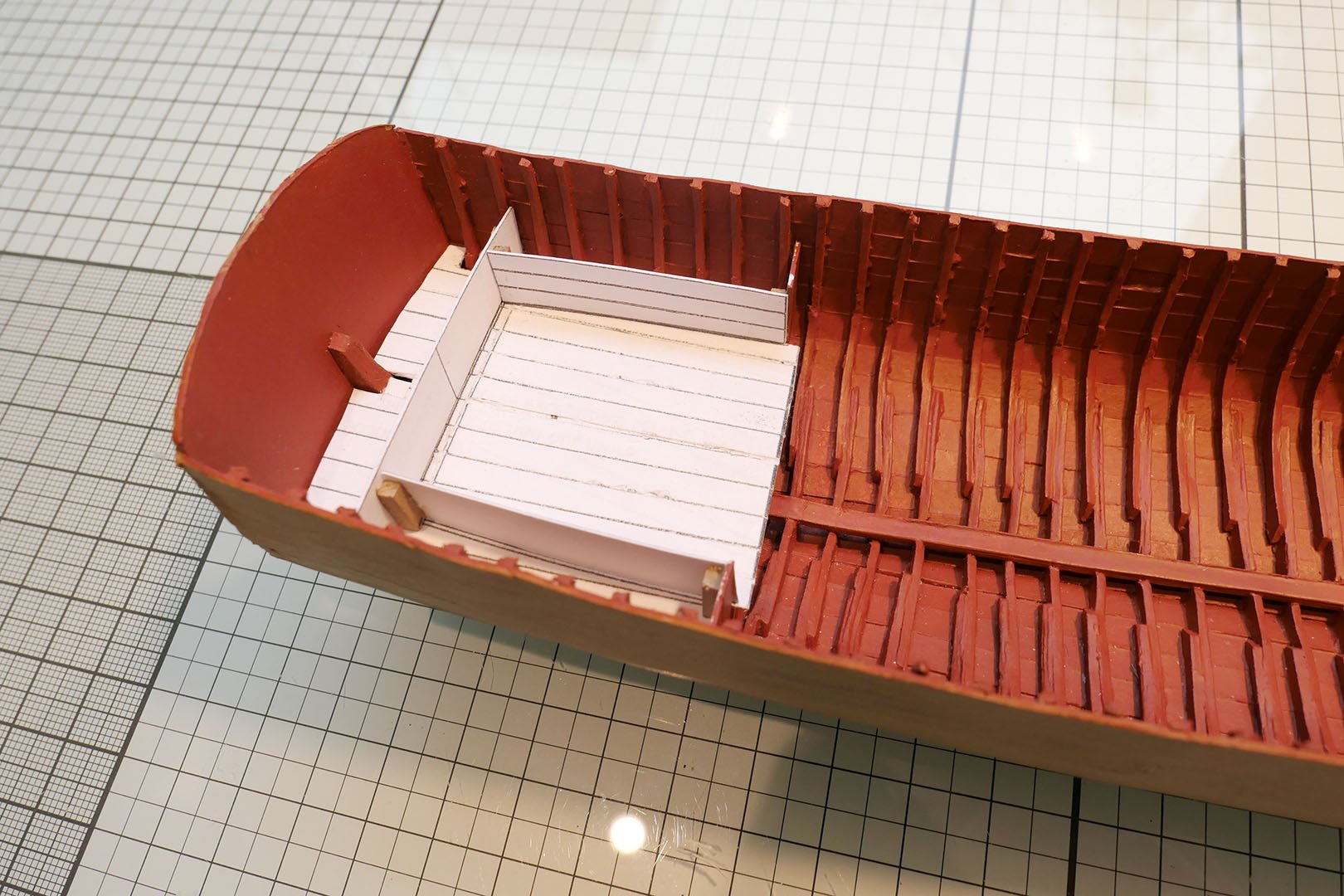
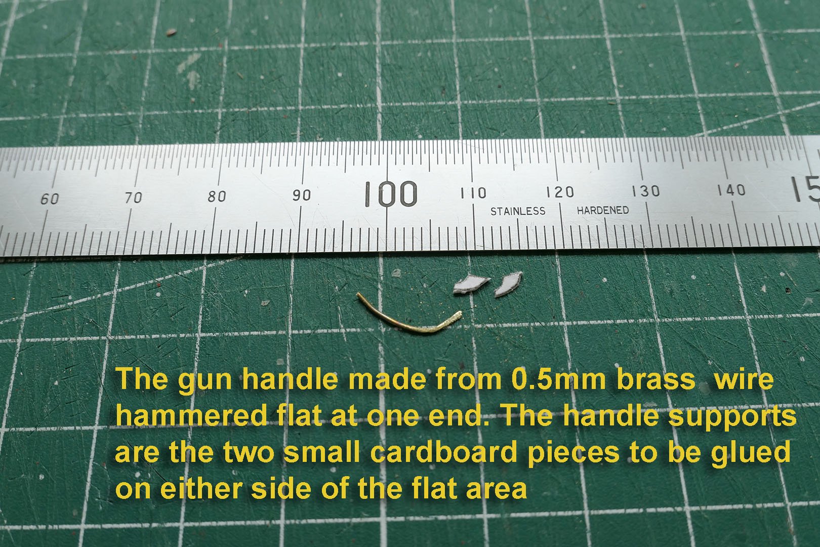
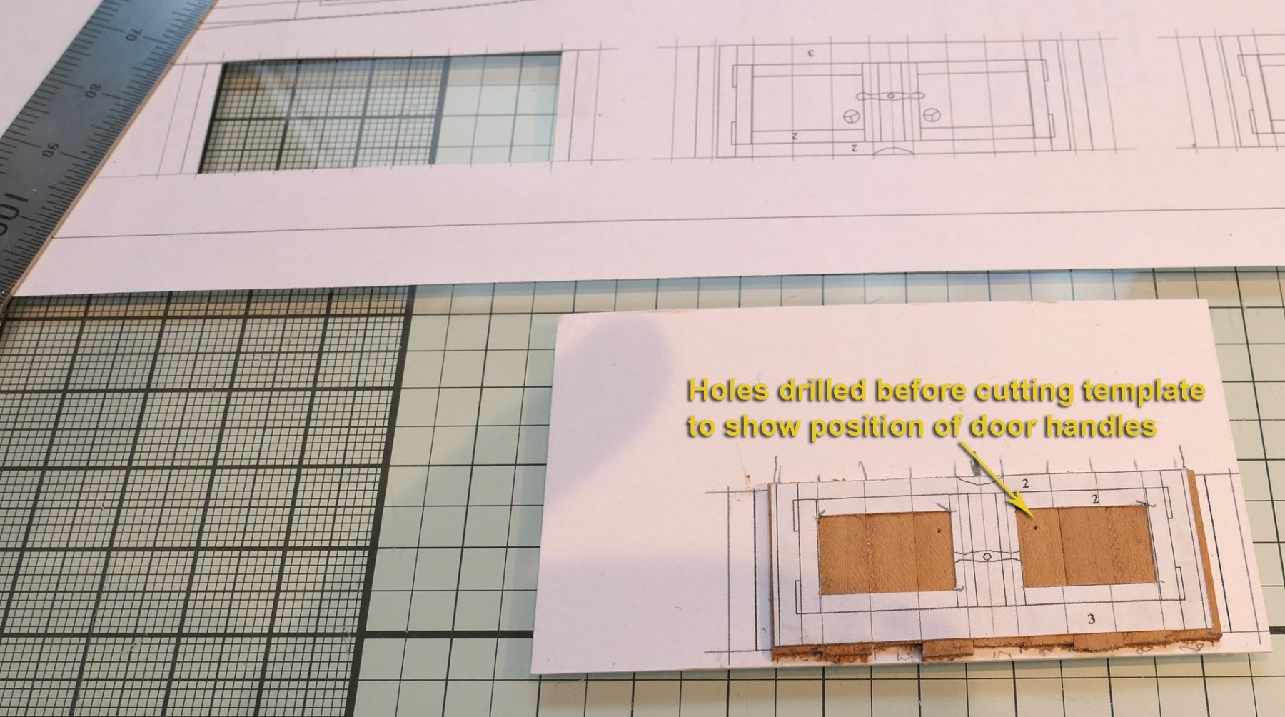
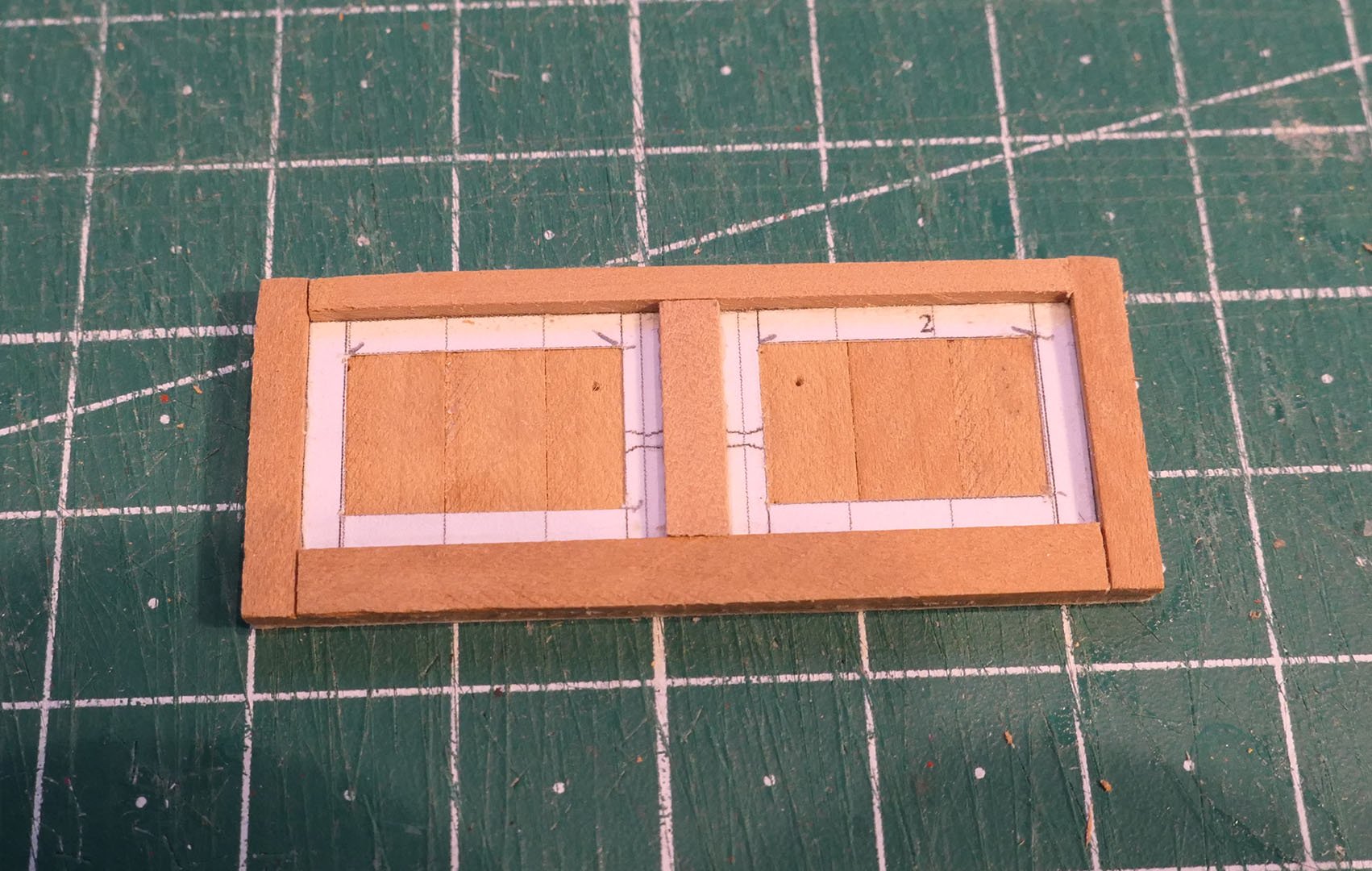
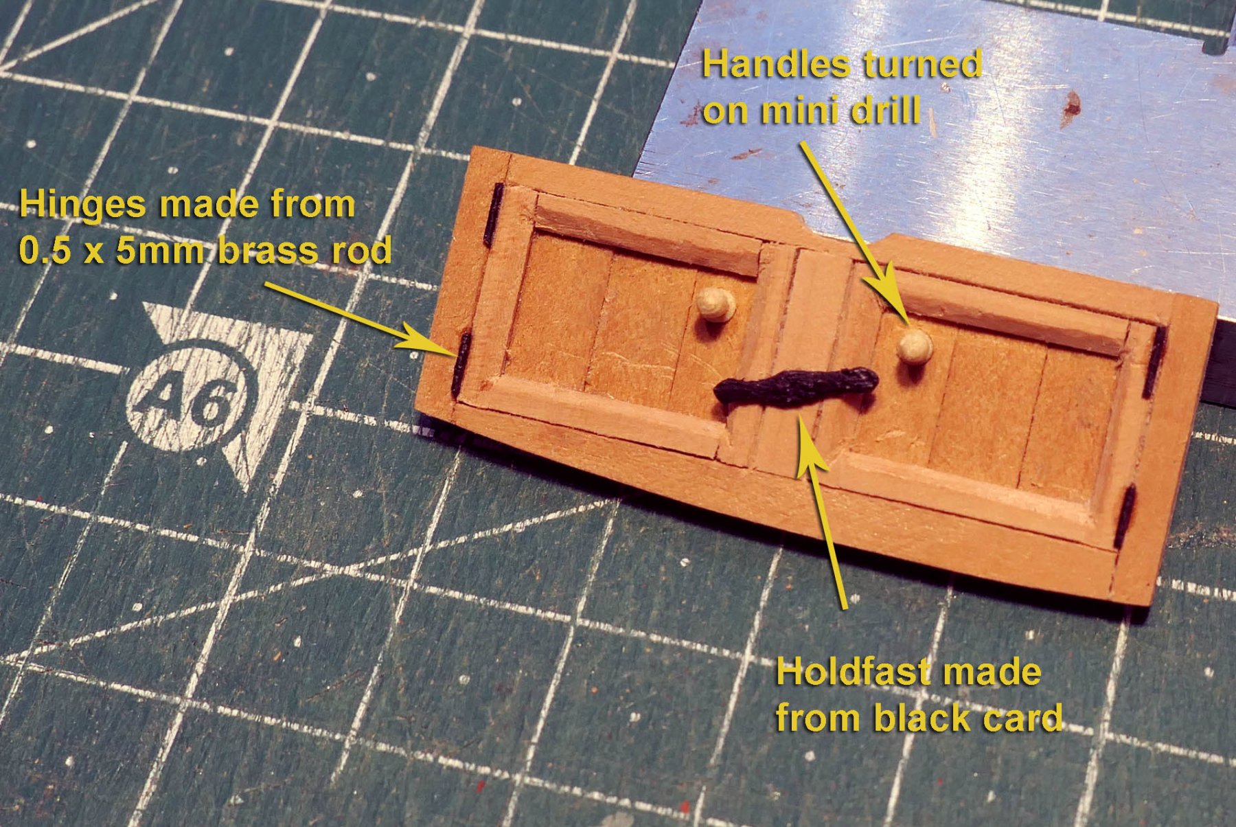
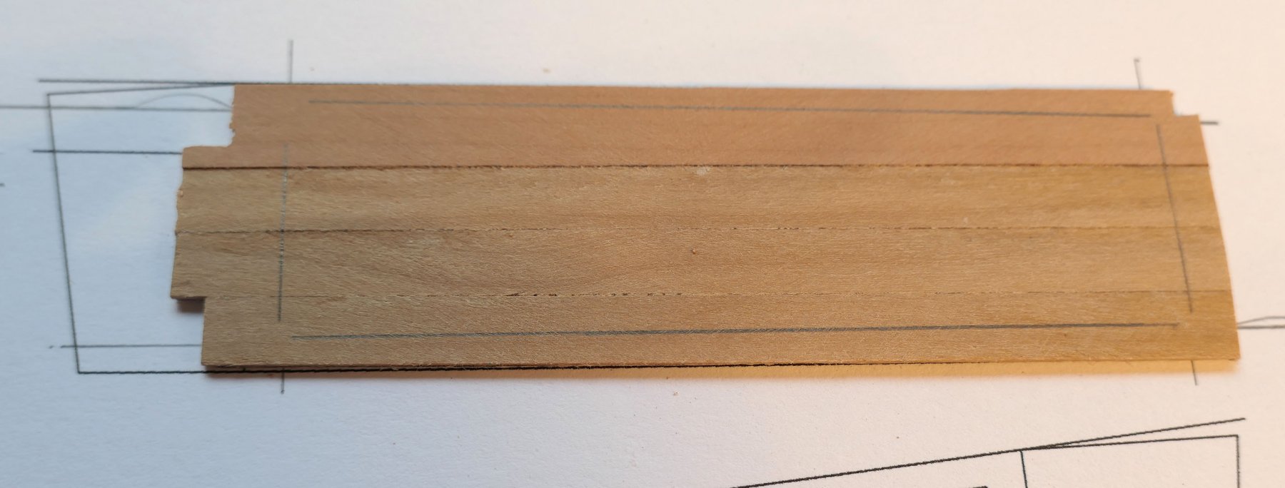
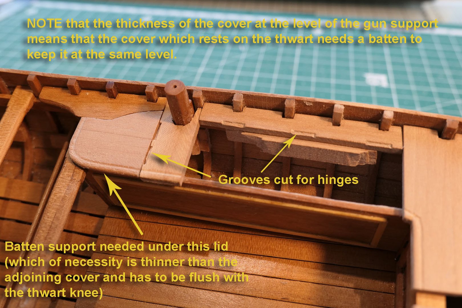
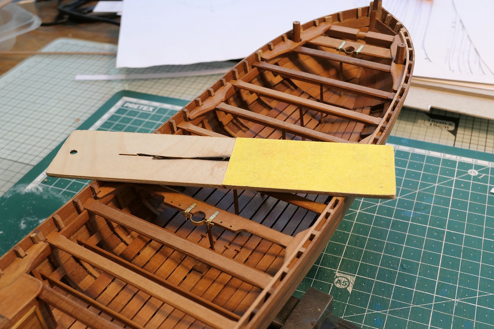
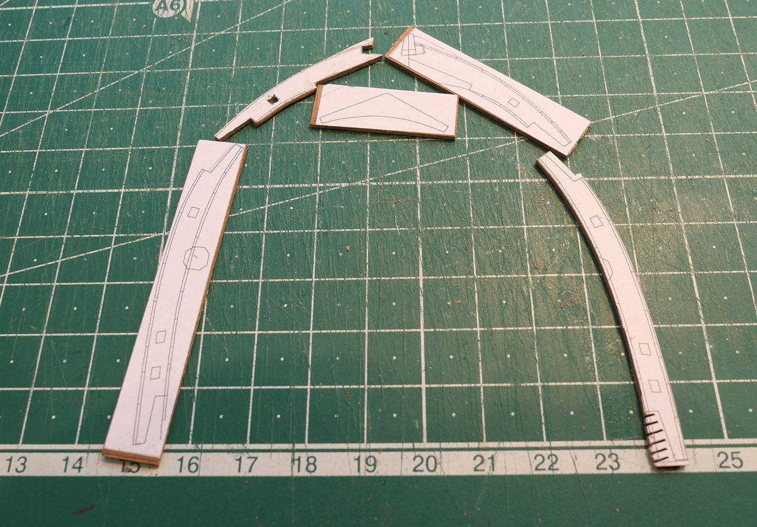
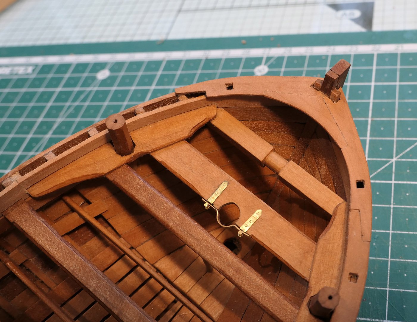
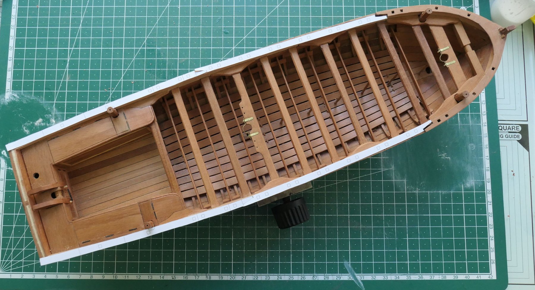
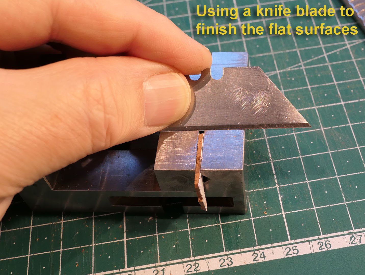
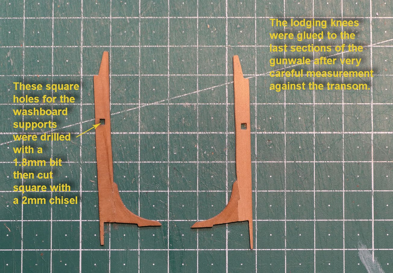
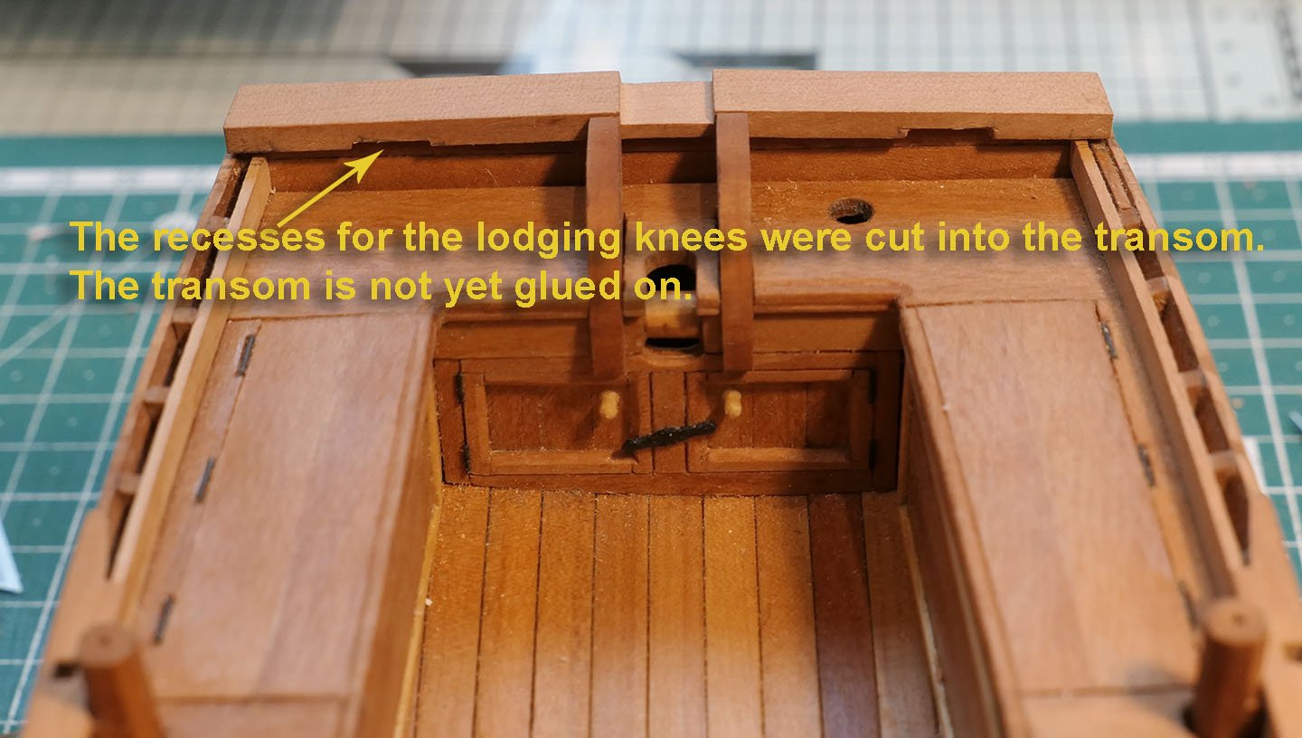
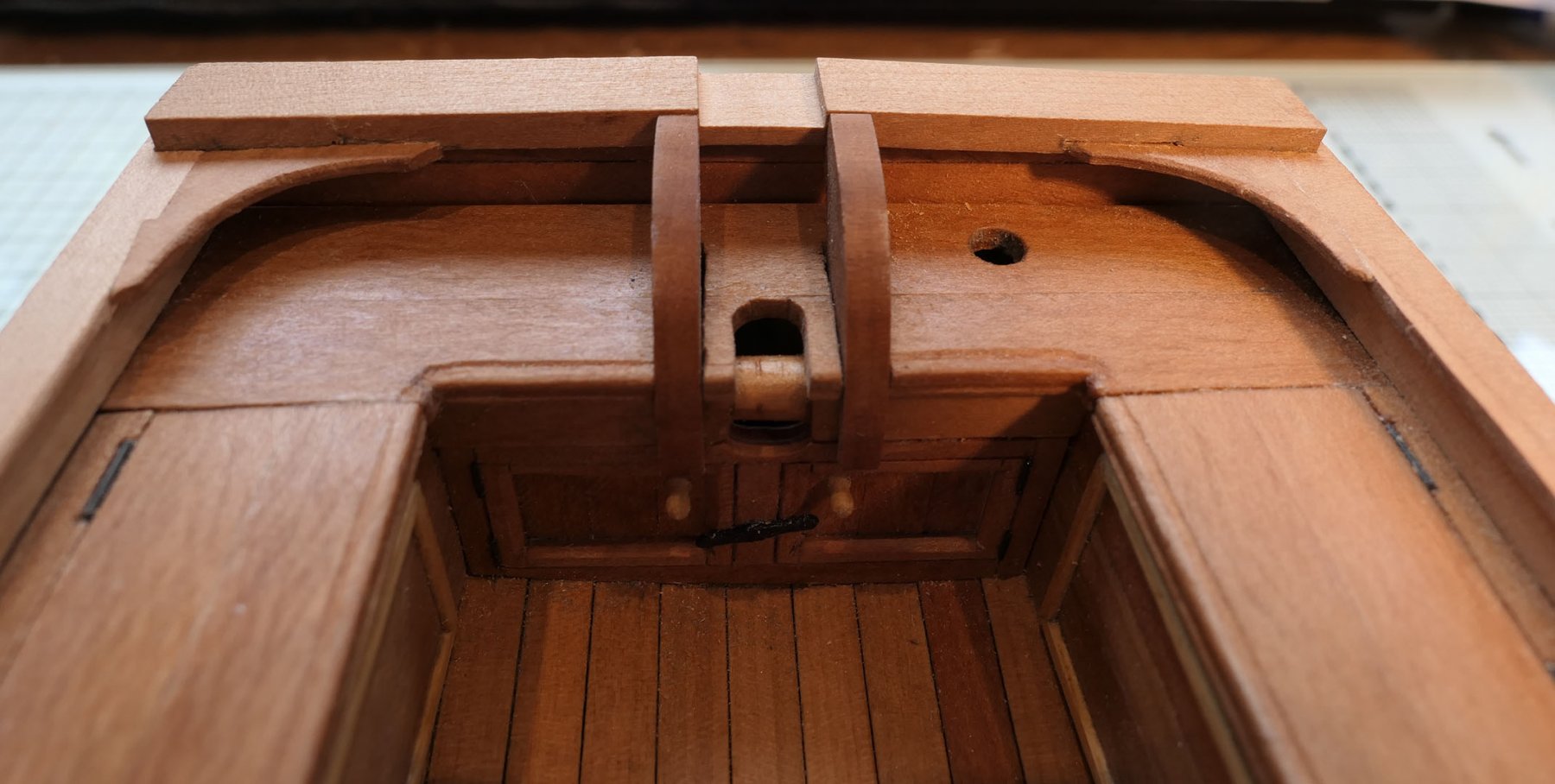
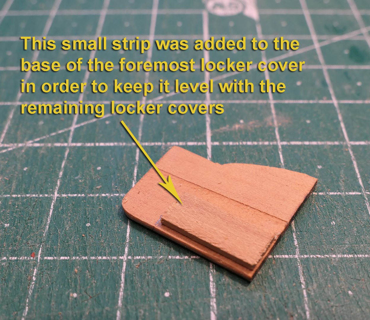
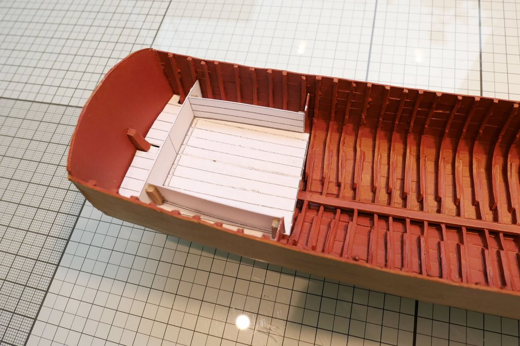
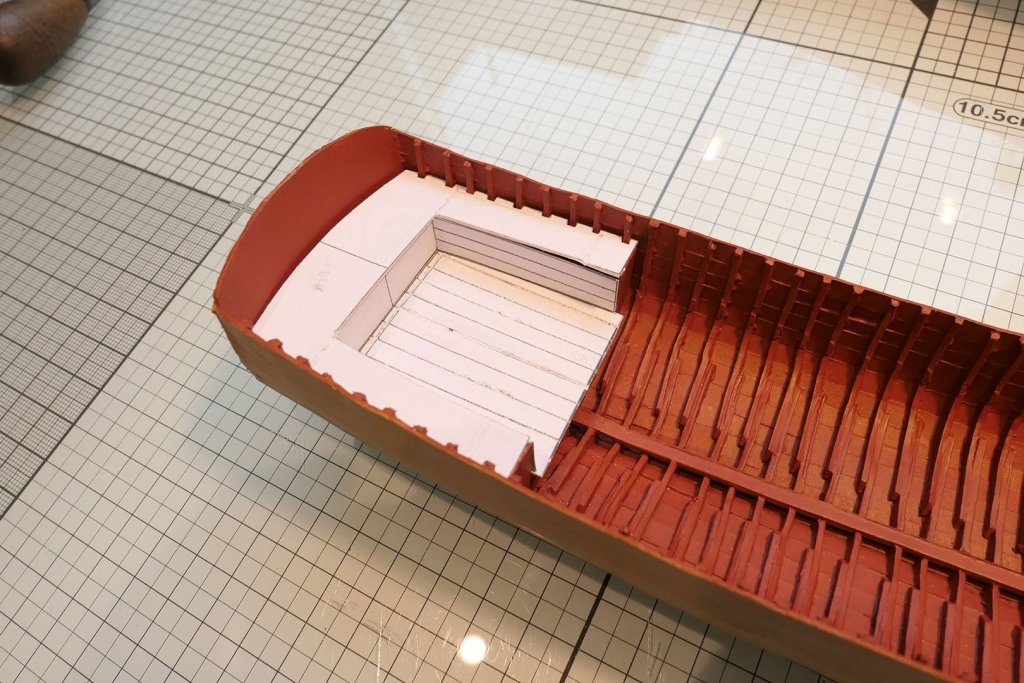
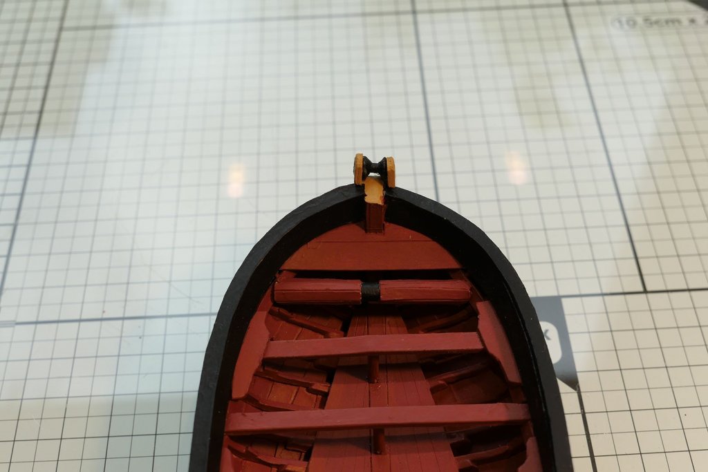
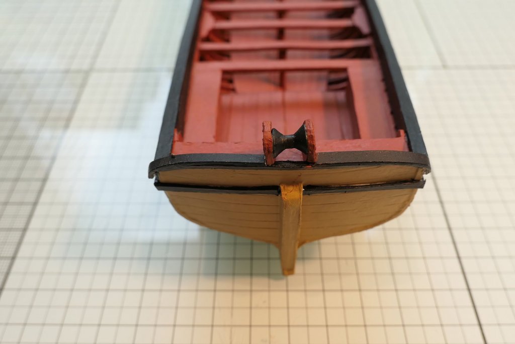
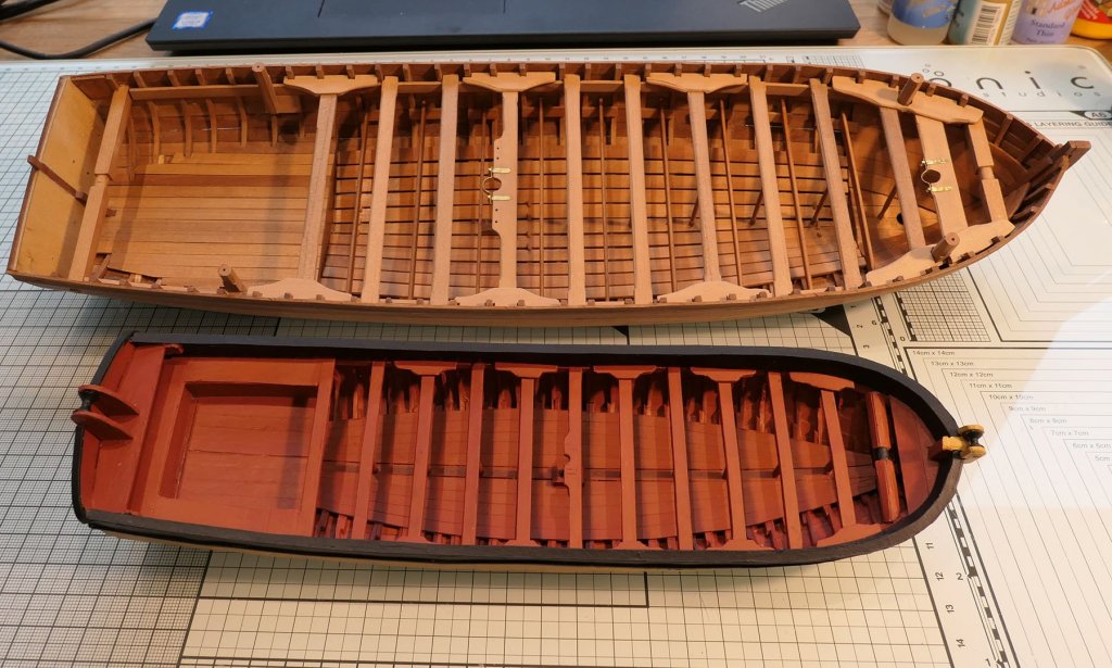
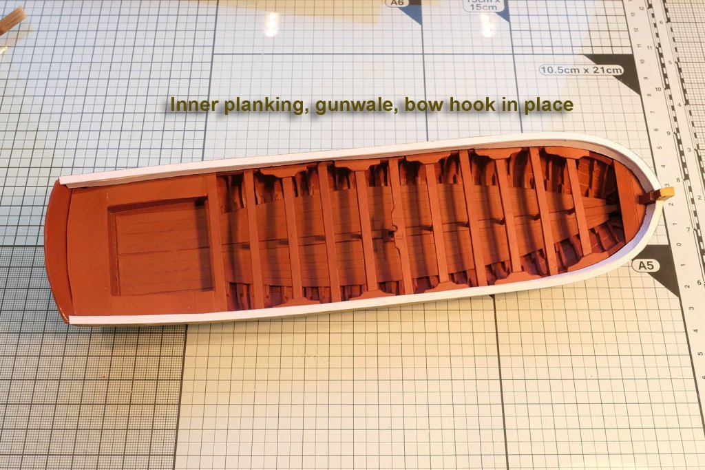
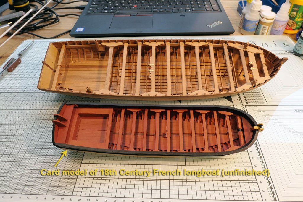
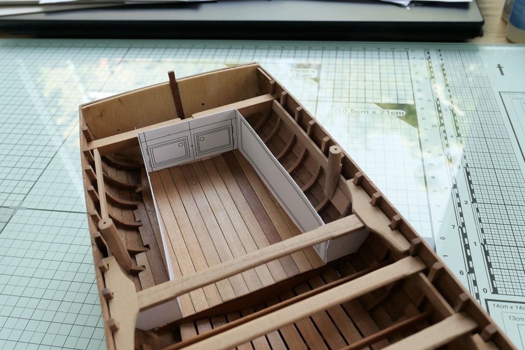
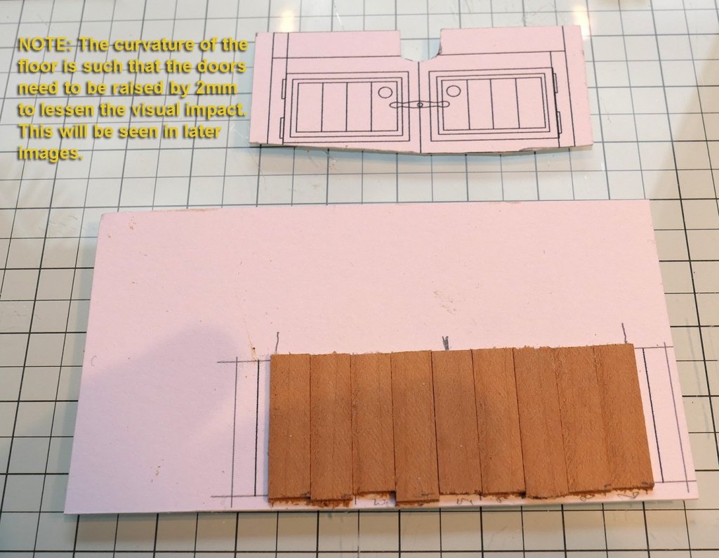
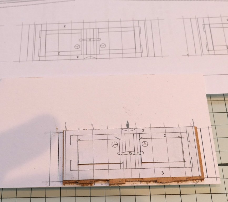
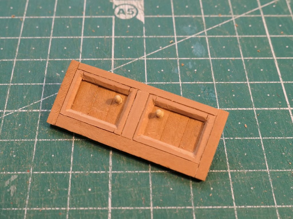
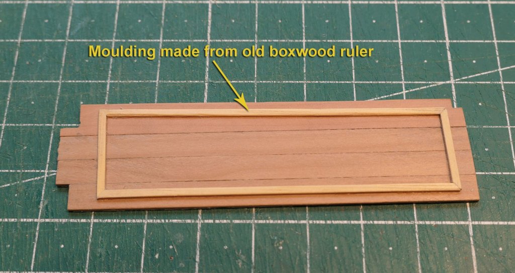
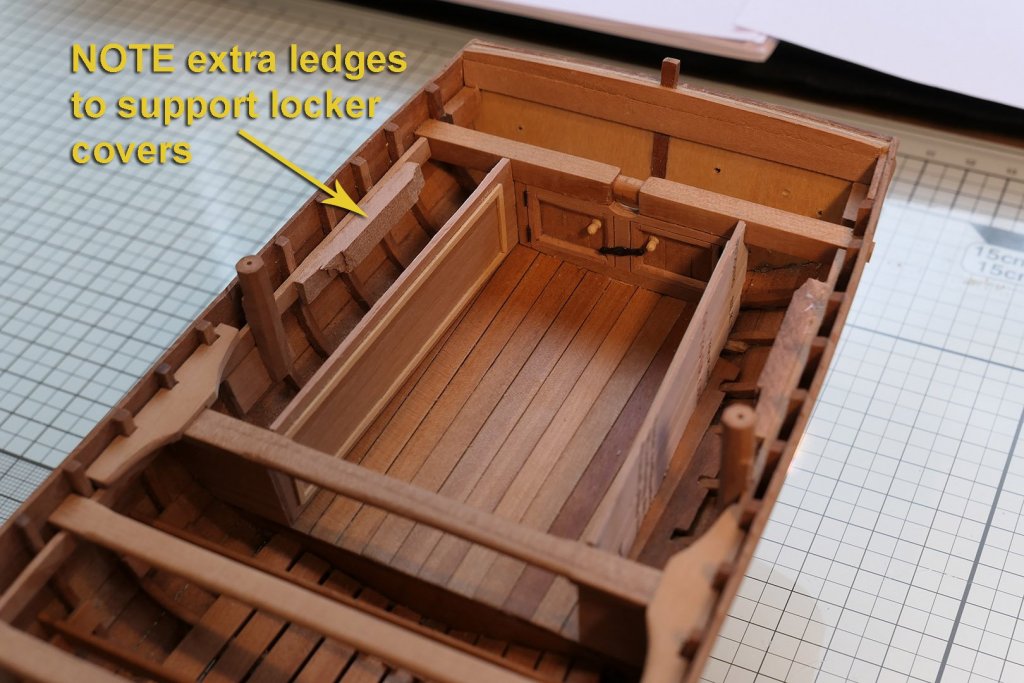
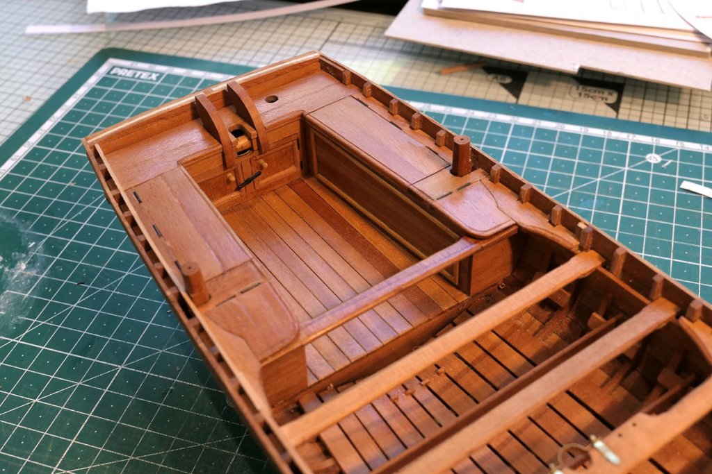
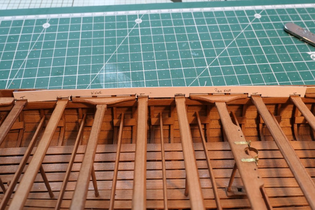
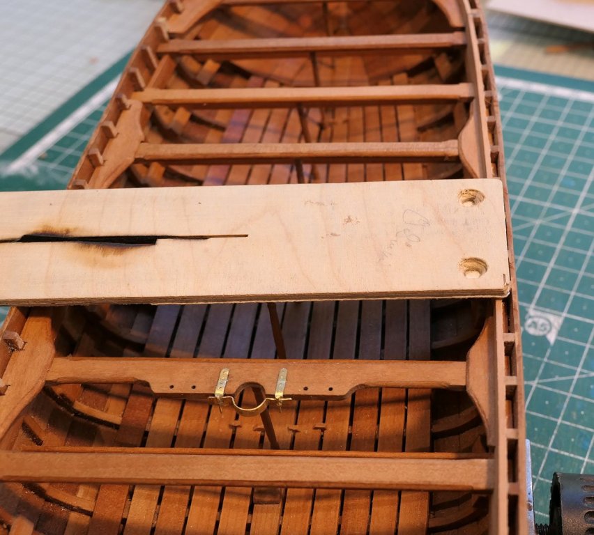
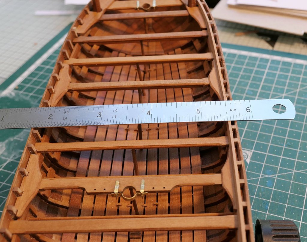
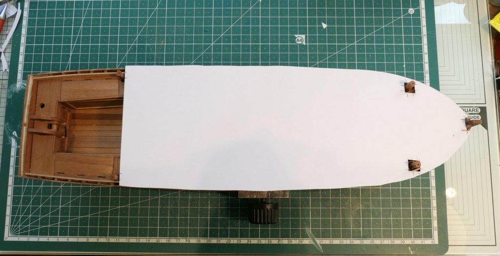
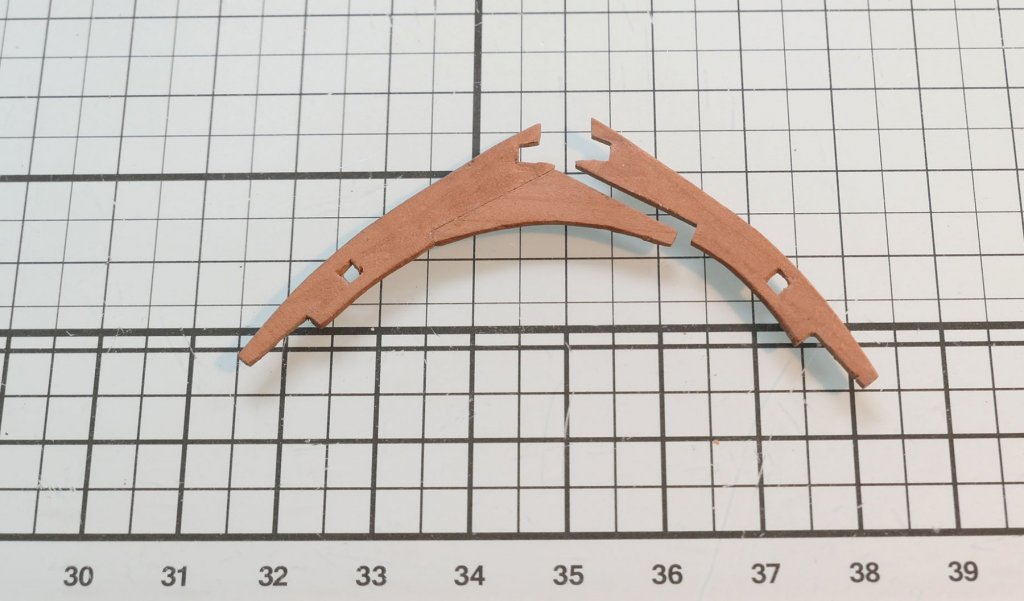
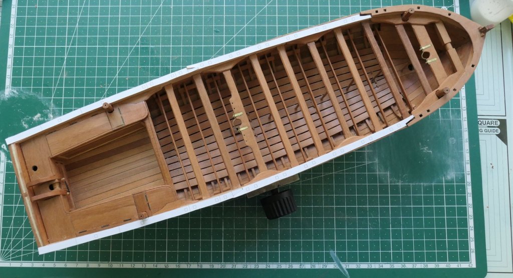
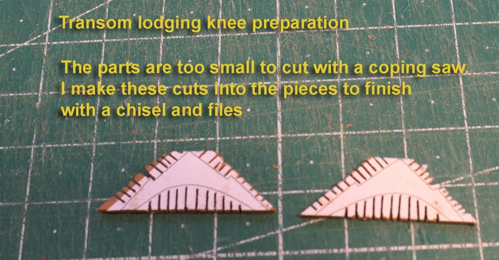
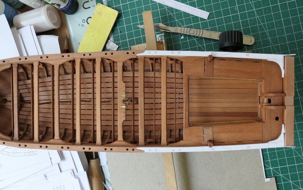
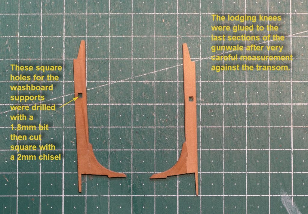
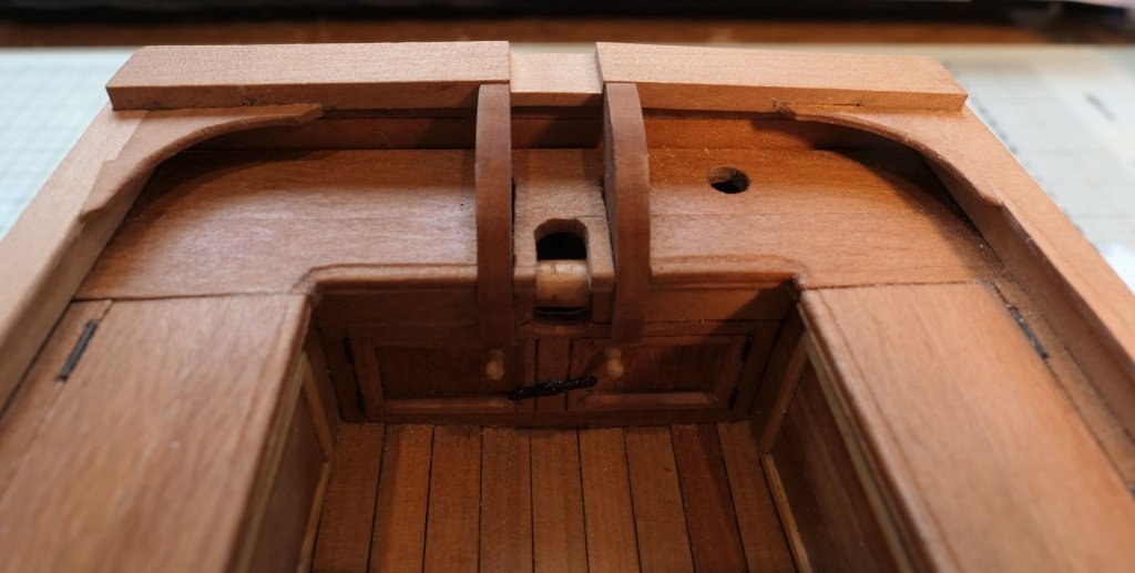
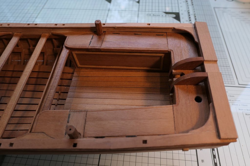
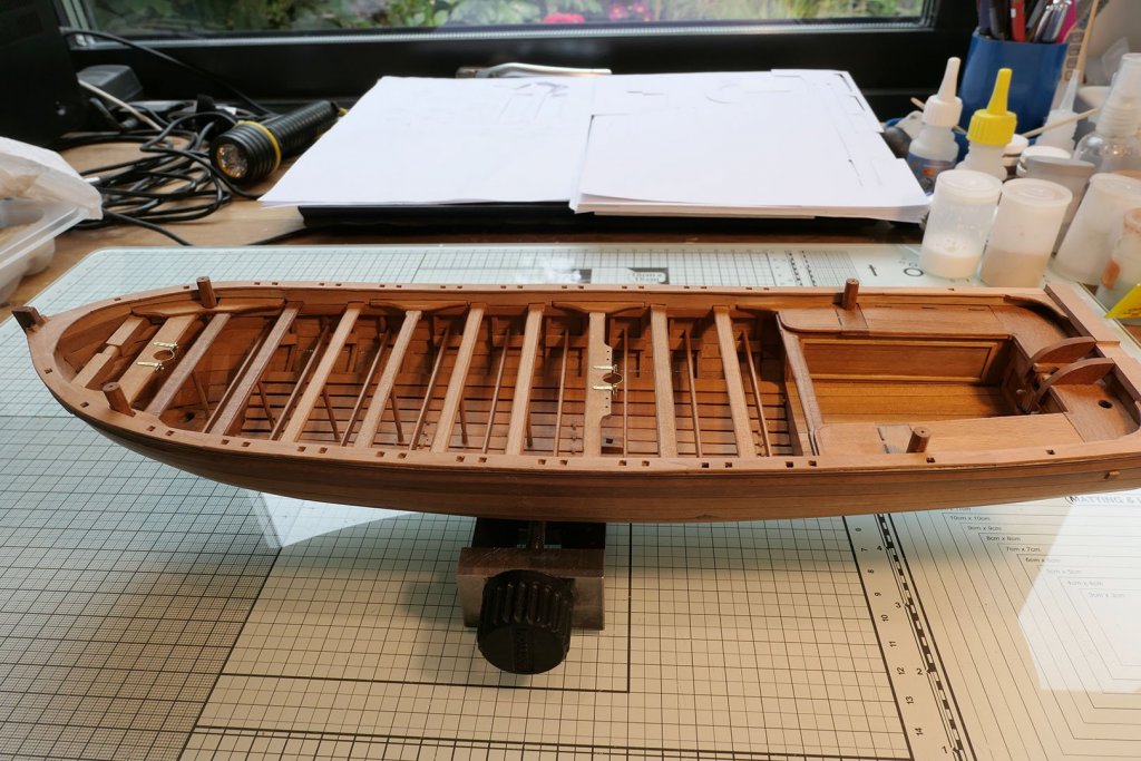
The last part of my build was posted in February. Since then, and while recovering from surgery, I used the time to experiment with the card model of the 18th Century French longboat that I mentioned. (I wasn’t allowed to cart around anything heavy like table saws for a couple of months). I’ll do a separate log for that, just to show how nice a model it might turn out to be for someone more experienced than I am with card. For the moment though, I can show the stage to which I had arrived in comparison with the Chaloupe: Rear Lockers A recurring theme in this (and my other builds) is damage limitation. Mistakes or inaccuracy early on lead to recurrent problems later in the build. The major problem in this build that I continue to face is the asymmetry resulting from slight inaccuracies in the original mould and not ensuring the true verticality of the frames. This has meant that I cannot simply make pieces according to the plans but have to make my own measurements and templates so that the pieces can fit together. Fortunately, this is something I really enjoy and see as an essential part of model building (or else it could mean that I’m too lazy to rebuild the model from scratch)! A good example of this lies in the making of the rear lockers and the gunwale. I finalised the measurements for the rear lockers using 0.3mm card templates. You’ll note that the floor of the cuddy is not straight and there’s a sub-millimetre difference in the length of the locker sides. In order to make the doors at the end of the cuddy, I used two layers of planking, with the rearmost layer glued to card. The side lockers were built in a similar way, using card as a base. The picture frame moulding was made from strips from an old boxwood ruler. I added extra support for the locker covers. I faced a small problem with the thickness of the covers. The foremost cover has to be flush with the thwart knee and lie on top of its thwart. However plan sheet 4 shows that the cover thickness at the level of the swivel gun support has to lie also level with the top of the thwart knee while resting on the thwart stringer below. To satisfy both requirements I added a small batten under the foremost cover to rest on the locker side. You can get an idea of the completed lockers in the following photo, which shows the davit timbers in place. The hinges are again non-functioning, made of 0.5 x 5mm brass rod. Finalising internal planking The next stage was to make the final strakes of the internal planking above the thwart stringer. These required multiple notches for the thwarts and thwart knees, so I used cardboard strips to define the cut outs first. Once the planking was in place, it was important to ensure it was level with the external rubbing strake. I used a flat board wider than the hull, partially covered with sandpaper. I then laid the end without sandpaper on one side and sanded the internal planking on the other side until it was level with the external planking. I then checked the level with a metal rule. Gunwale Clearly, the outline of the hull on the plans would not match the plans because of the small variations I have already mentioned. In order to find the shape, I used a card template as suggested in the monograph. The monograph also suggests to make the gunwale in one piece, although it also says it would have been made in several sections. I decided to make it in several sections – not only for the sake of accuracy, but mainly because I predicted to myself that I would make mistakes and thereby waste a lot of wood in the process. So in my tracing in the CAD programme I inserted a number of scarf joints. I started with the bow and the saddle joining the two sides. Before fitting these pieces, I glued the saddle to one side, glued that assembly to the bow, then added the final section around it. Transom lodging knees The transom lodging knees require careful cutting out. The picture above shows one piece for the last two sections of the gunwale. This was just for measurement purposes. The two sections were cut separately. Next up will be finalising the transom with its roller, putting bands on the davit timbers, making the washboards. Tony


- 124 replies
-
- 21
-
-
- longboat
- Chaloupe Armee En Guerre
- (and 1 more)
-
Neat work on the gunports. Don't forget to check the height (top and bottom) with the guns by putting in temporary decking before you finalise them. You can use cardboard cutouts of the profile of the guns in their carriages. I remember the ports giving some trouble in this adjustment. Tony
-
Of the choices you provide I'd go for the last one with the flat angled top. Tony
- 84 replies
-
- 2
-
-
- sherbourne
- caldercraft
- (and 2 more)
-
To align at 90 degrees, you can straighten the scans by using a vertical (or horizontal) line on the drawing (e.g. a station line), superimposing a straight line with a photo editor and then using that line to rotate the whole drawing. After doing that you make all the distortion adjustments and then the superimposition of each of the subsequent scans. Tony
-
Just to add to Mark's post, you need to remember that ordinary scanner distortions occur in all axes (not necessarily those of the architectural scanners). You can't be absolutely perfect, but you can at least adjust the horizontal and vertical axes independently. The problem is that the distortions also change depending on the position of each part of the drawing. So distortions at the centre are different from distortions at the edges. For that reason I take scans that overlap by at least half the width of the preceding scan, and then similarly of the length as I go down the plan. You can then use the transparency layers in your photo editing programme to overlap the scans accurately. It is after this overlapping that it is best to do the final horizontal and vertical adjustments. The way I do it is to look at the scanned image in Photoshop or TurboCAD and then take accurate measurements of the horizontal and vertical at their widest possible margins. Taking smaller lengths increases the possibility of inaccuracy. I then enter these dimensions in a spreadsheet (or a calculator) and divide them into the distances measured on the plans. You will very likely find different ratios for the horizontal and vertical axes. These ratios are then used to re-size the images in a photo-editing or CAD programme. So if the horizontal axis is found to be 1.04 times that of the paper plan, you simply divide the length on the scanned plan by a factor of 1.04. Sorry if this is all very obvious, but I'm adding this info just in case you might assume that the distortions are consistent. Tony
-
I just scanned mine on overlapping A4 sections then joined in Photoshop after a bit of readjustment for distortion. As you say, they were not very accurate, but proved to be accurate enough for the deck layout. You need to work with card cutouts to achieve final shaping here and there. The page in the manual with the pictures of the bulkheads came in very handy to determine the waterline for my own model (I created a blue perspex 'sea' for the model to lie in). The drawings of the bulkheads I found to be the exact size of the parts in the kit. Tony
-
I forgot to mention that the reason for buying white card is so you can print to it if you want after using a CAD or illustrator programme to create or copy parts. Ordinary card from cereal boxes etc is more than adequate just for experimenting. Tony
- 84 replies
-
- 1
-
-
- sherbourne
- caldercraft
- (and 2 more)
-
To do the edging it's useful to make cardboard templates until you have the hang of it. You can then use Pritt stick to glue them temporarily to the wood so you can cut it accurately. To remove the card just damp the top very slightly with water and then when dry sand the wood down to remove any traces of glue. Some people use rubber cement to do this but I find it more problematic to remove. I have reached the stage where I just tear off the card without water and scrape the residue off with my nails, then sand. That way you don't have to wait till the wood is dry before fitting. This is a cheap and effective method to find the right cuts in a wide variety of situations. The card I use is stock card about 0.3mm thick. You can get 50 sheets of A4 at this size at https://papercutz.co.uk/a4-card-white-printer-and-crafts-220gsm-280micron This costs only £5.32 and will last you a very long time. For larger projects you can also get larger sizes of card. Tony
- 84 replies
-
- 2
-
-
- sherbourne
- caldercraft
- (and 2 more)
-
I do agree about the treenailing. In fact plank nailing on the hull is also only visible faintly. Look at a deck from a distance of 64 feet and you'd be pushed to see it at all, just as you would a foot away from a model that is 1/64th the size of the real one. On deck planking I use a wax of the same shade as the deck to fill the holes if I do it at all, and I don't do nailing of hull planking. To my mind (and I stress that this is just a personal view about my own practice) doing this just draws excessive attention to the nailing and therefore to the skills of the modeller rather than the overall impression of a ship -- but then this is against the general convention and most would disagree with me. You could argue that I just don't have the skills to do it properly! Tony
- 84 replies
-
- 1
-
-
- sherbourne
- caldercraft
- (and 2 more)
-
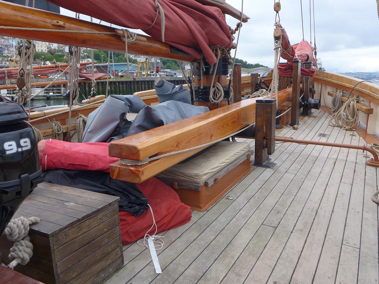
B looks better. I use a soft lead pencil on one side only. On real ships the caulking was not precisely defined, being a little fuzzy here and there. I attach a picture of the renovated Brixham trawler Pilgrim: Tony

- 84 replies
-
- 3
-
-
- sherbourne
- caldercraft
- (and 2 more)
-
I'm not a sailor, so I can't really comment on the height of the boom in terms of sailing. Its function is to be movable laterally and vertically, so in terms of structure there would be little problem as you can set it to whatever height you want with the rigging. However, the transom does look very high to me and I'm not clear of the need for it to be so high. The original plan which I posted earlier would seem to be a good indication of the height. Tony
- 84 replies
-
- 1
-
-
- sherbourne
- caldercraft
- (and 2 more)
-
Yes, the plans point to a housing, while there's a scuttle next forward. However, as you say, these cutters differed in their anatomy from shipyard to shipyard. I'll look up the Alexander Kent books, so thanks for the recommendation. Tony
- 84 replies
-
- 1
-
-
- sherbourne
- caldercraft
- (and 2 more)
-
Sorry, Edward, I forgot to add the second plan which shows the deck details I was alluding to in the post. I've now edited that post so you can see what I was talking about! Tony
- 84 replies
-
- 1
-
-
- sherbourne
- caldercraft
- (and 2 more)
-
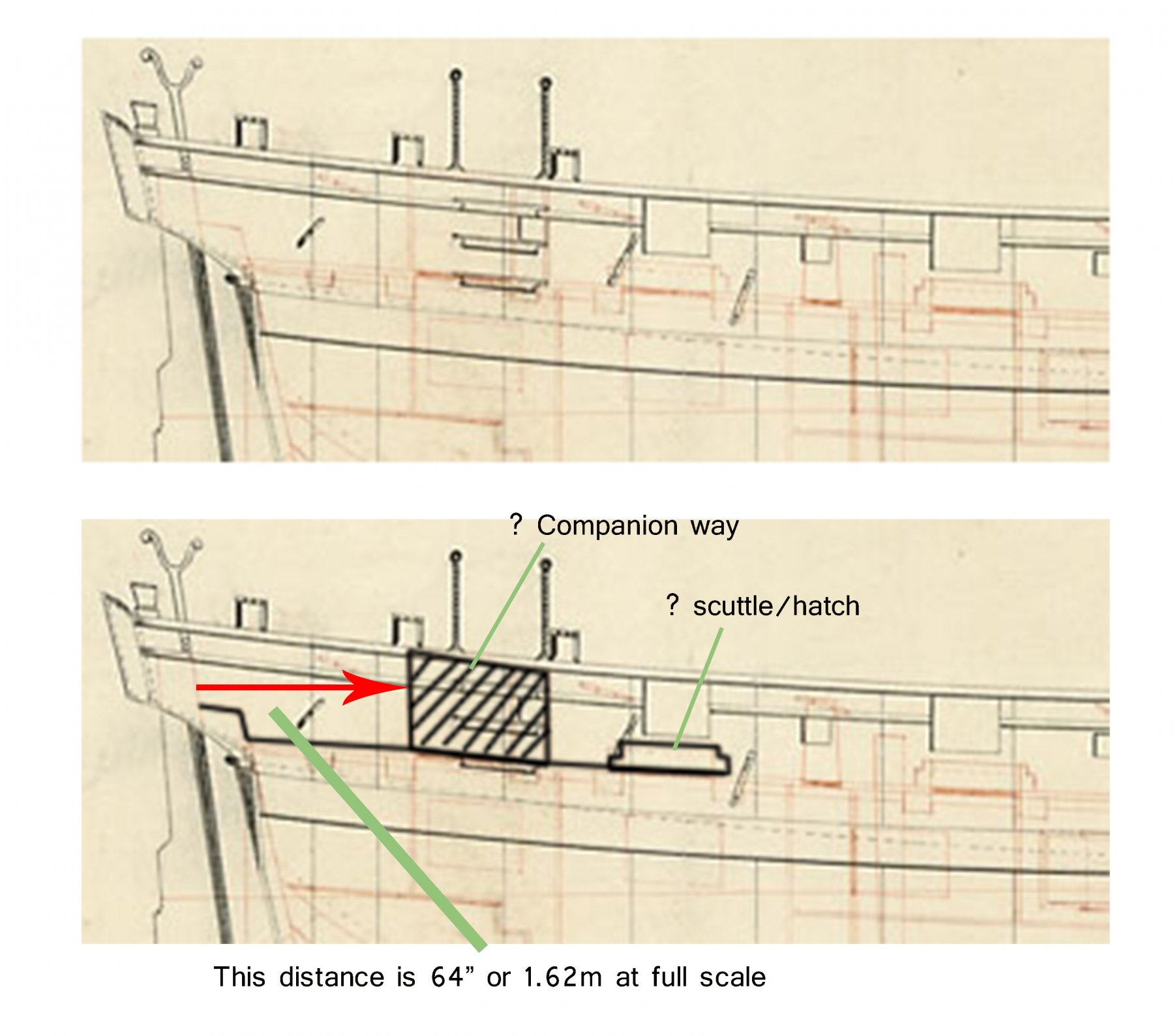
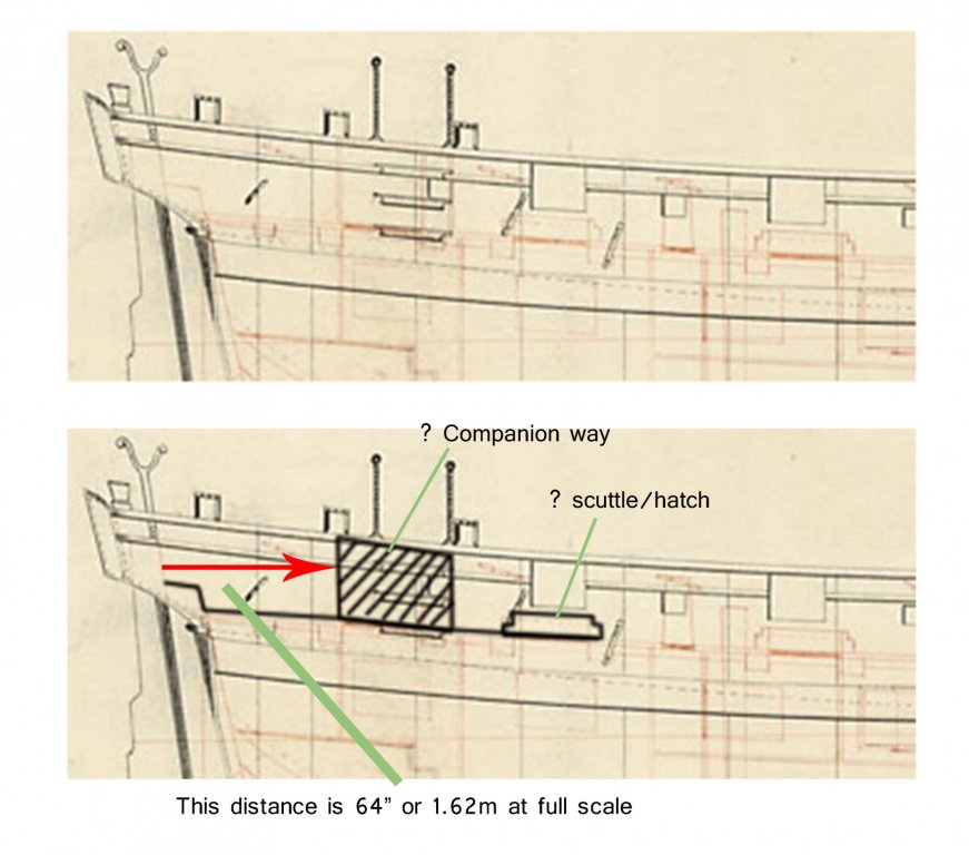
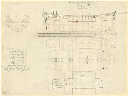
The planking is symmetrical, and all you need now is filler followed by sanding. The original plans for the Sherbourne show the rearmost entry as a companion way, then comes a scuttle. I interpreted that scuttle also as a skylight for the cabins below. As to the design of the companion way, you can see different interpretations of that on the various builds. I attach the relevant drawing (the plan is from the low res distorted jpeg from the NMM site: you can order the full originals from them if you intend to do this seriously but note that it is sometimes spelt as Sherborne or as Sherborn). In the above low res plan from the NMM website, note the top of the companion way and the placement of the vertical line on the lid. I interpreted that as signifying the companion opened towards the front. You'll notice the design of the windlass is quite different from that of the kit. There's also the one gunport with a lid, the boom crutch, the galley stove pipe and the hand rails at the top of the steps. All these aspects were, I think, discussed in the different logs (as well as on separate question discussions) so it would be worth while digging a bit more if you're going after historical accuracy (which you don't need to, of course!). Just search for Sherbourne on the site. I hope this helps. Tony
- 84 replies
-
- 2
-
-
- sherbourne
- caldercraft
- (and 2 more)
-
If you want to try out the full spiling route on the planking, then it might be good to go for wider strips overall so you can cut according to the width required at each part of the length. You could practice that on the first planking, although it would mean buying more wood. I've used Cornwall Model Boats mostly in the UK, although I've also used Jotika and Model Dockyard in Cornwall. Tony
- 84 replies
-
- 1
-
-
- sherbourne
- caldercraft
- (and 2 more)
-
First planking just gives the base and you can sand and use filler, so there's not much problem there. One of the reasons to leave the stem, keel and stern timbers off until you've done the planking is to allow you to sand the planks down more easily, but I (like you) had not known that because the instructions tell you to put them on first. In order to make it easier, I ordered 0.5mm thick planks for the second layer in order to fit to the timbers more easily. I used 5mm widths for most of the planking but 10mm strips for the garboard as that can't be done with the narrower strips. All the same, if you protect those timbers it just takes a little more care to achieve a good result, especially if you follow the planking tutorials available in the articles database of this site. I found it easier to start with the garboard planks. For a really good result you might want to separate the planking into bands as suggested by the tutorials, but I didn't. It also helps if you fill between the bulwarks before planking, certainly at the bow where the curvature is more pronounced, and at the stern. That gives the planks something firm on which to rest and to make a good curve. Don't forget that the details of the planking won't be noticed too much if you're going to paint below the waterline. On the question of gluing, I find it easier to use a pointed stick such as a cocktail stick. You don't need much to glue a joint. It's more important to ensure a really tight fit. As for lighting, I agree it's very important to have the area well lit. I use a magnifying lamp as well as an anglepoise. Tony
- 84 replies
-
- 1
-
-
- sherbourne
- caldercraft
- (and 2 more)
-
Good start. Seeing as you've already fitted the stem, keel and stern, it would be a good idea to cover them with tape to avoid the inevitable scratches etc as you get on with the planking. Tony
- 84 replies
-
- 1
-
-
- sherbourne
- caldercraft
- (and 2 more)
-
It would be good if you could specify a particular ship as there are quite a few variations in that period. There are hundreds of plans at the National Maritime Museum at Greenwich in the UK. For the particular date you choose (1790) there's the Cutter Trial which had sliding keels. You can see the range of its plans and pictures at https://collections.rmg.co.uk/collections.html#!csearch;searchTerm=cutter_1790 I have also taken quite a few pictures of the model in that collection which you can see on this site at There are also lots of pictures of other cutters between 1763 and 1820 in the discussion at I hope that helps Tony
-
Fear? I live in dread of every new step. I look at the plans. I look at previous builds. I read the books. But believing I can do it is a whole other matter. OK. I make a stab at it. I make a mistake. I start again. I make another mistake. I go on until I reckon I can live with the mistake. Then the next step. Several steps down the line I find I've done something which makes the next step very difficult. Think .... and this is the exciting bit ... how to get around the mistake and carry on. Ha! I've found a way out. I can then continue. And so on. I really like modelling not only for the satisfaction of completing a build and the beauty of wood, but even more for the satisfaction of thinking. Thinking how to interpret plans. Thinking how to approach a problem. Thinking of how to overcome mistakes. Thinking about the skills of those who made the ships and sailed in them. I am sure that in your life of working with wood you've experienced something similar. So to my mind fear, anxiety and apprehension are an intrinsic part of the process. Getting over it is part of the satisfaction. Tony
-
Bear with you? I'll do more than bear with you. I'll follow your build avidly. It's a great model to start with, especially as there are so many pieces you may well find yourself improving or modifying as you get into the swing of things. There's no single 'correct' way of finishing it, as you will have found out from the various builds, so no need to worry: you'll be doing it right! Tony
- 84 replies
-
- 1
-
-
- sherbourne
- caldercraft
- (and 2 more)
-
That's how the modellers on the French forums/fora interpret it. It's worth having a look. In addition to the ones I have mentioned, there's Marine & Modélisme d'Arsenal at http://5500.forumactif.org/. The pictures tell you most of what you want to know. Tony
-
If you look on the French modelling forums there's plenty of discussions about the rigging and history of La Toulonnaise as a topsail schooner. For example, from the Forum Marine at http://forummarine.forumactif.com/t3369-la-toulonnaise-construite-en-1823: "Lancée à Toulon le 13 août 1823, la TOULONNAISE prit part à la guerre d'Espagne sous les ordre du commandant JOURSIN, stationna à Barcelone puis atteignit Cadix ou elle contribua au canonnage des équipements portuairesEn 1832 à Brest le navire fut soumis à une révision complète. Pour les puristes ce vaisseau aurait été armé de Caronades" Which translates as "Launched on the 13th August 1823, the Toulonnaise took part in the Spanish war under the command of commandant Joursin, stationed in Barcelona, then at Cadiz where she contributed to the bombardment of the port. In 1832 at Brest the ship had a complete re-fit. Purists tell you she would have been armed with carronades." The discussion on La Royale Modélisme says in addition (http://www.laroyale-modelisme.net/t15358-la-toulonnaise-goelette-de-1823-au-1-75-maquette-musee-marine-auto-bce-n-36-2015?highlight=la+toulonnaise): "Elle contribua à la répression de la traite des noirs sur les côtes d’Afrique. Elle participa aux opérations d’Alger en 1825. Ses périples la conduisirent alors à Cayenne, en Martinique, à Terre- Neuve. En 1832, de retour à Brest, le vaisseau fut soumis à une révision complète. Elle resta ensuite dans les Antilles. En 1836 elle fit l'objet d'une nouvelle campagne de réparations à Fort de France. Elle croise ensuite durablement dans les eaux des Caraïbes. Enfin elle revint à Brest en 1843 où elle fut radiée des listes de la flotte le 18 décembre." Which translates as "She contributed to the repression of the trafficking of black people on the shores of Africa. She took part in the operations at Algiers in 1825. Her voyages then took her to Cayenne, in Martinique, at Terre-Neuve. In 1832, on return to Brest, the ship was completely re-vamped. She then stayed for a while in the Antilles. In 1836 she had further repairs at the Fort de France. She then cruised in the Caribbean. Finally she returned to Brest in 1843 where she was de-registered from the lists of the fleet on the 18th December." In all the builds on the French fora the plans from the Musée de la Marine are followed with the deadeyes as shown. They are also shown in other schooners of the time and their recreations. I can't vouch for the validity of these statements, but I hope this helps, Tony