gjdale
-
Posts
4,894 -
Joined
-
Last visited
Content Type
Profiles
Forums
Gallery
Events
Everything posted by gjdale
-
 Thanks guys - a small tweak with the pliers just prior to fitting the mast cleats it shall be then. I really appreciate the input folks - constructive criticism really helps to achieve the best possible outcome. Thanks for keeping me "honest". B.E. - silver soldering is not at all difficult. I'm still quite a novice, but seem able to get by to meet my needs. There is a good tutorial in the downloads section of the site. With your evident abundant skill set, I expect you will master it in no time at all.
 -
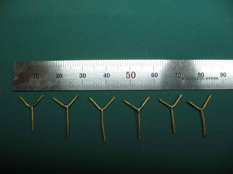
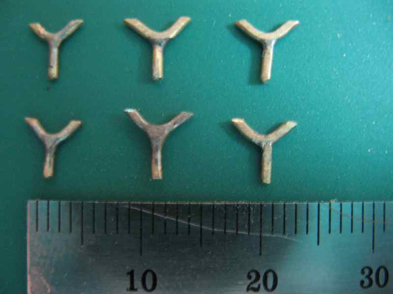
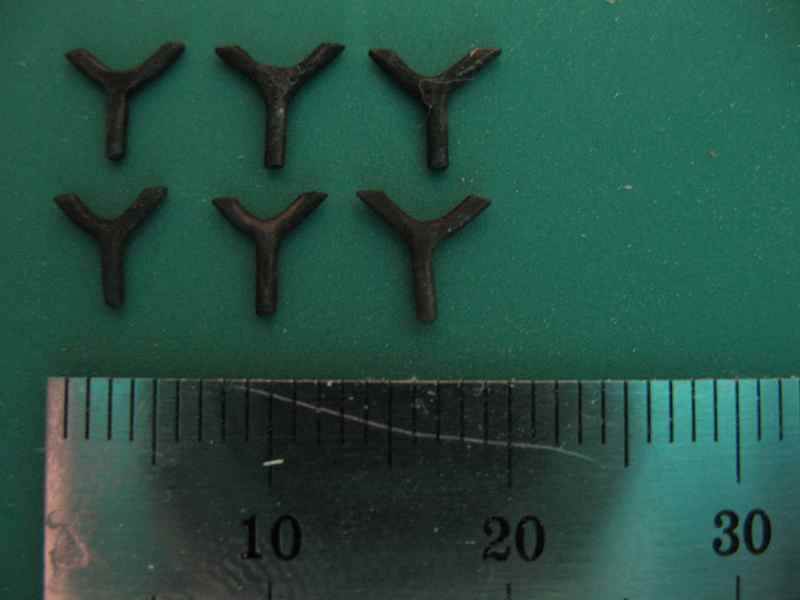
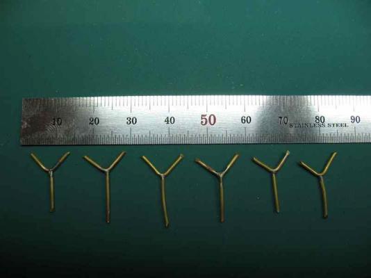
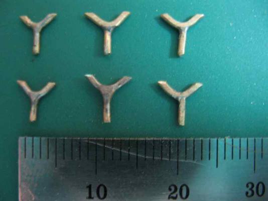
Thanks Lawrence and Augie, and the "likes". I think even Mobbsie will be satisfied with this version! I've been pondering the Mast Cleats as well over the last few days and came to the conclusion that making wooden ones just wasn't going to do it - they would either be too large/chunky or too fragile. So I got an idea from B.E.'s Pegasus log, where he had made some brass cleats from eyebolts. That got me to thinking in terms of brass, and eventually I hit on the idea of making them in two parts (one for the "stem" to mount into the mast, and one for the "horns") and silver soldering them together. So that's what I did...... Starting with some 1mm diameter brass wire, and cutting two pieces, with one bent at a right angle. I deliberately made each part extra long to make it easier to handle. Then a quick visit to the garage and a few minutes with the silver solder paste and mini torch: Then cleaned them up with a file and cut each leg of the "Y" to size: And finally, chemically blackened using Casey Birchwood Brass Black (thanks Danny for putting me on to that stuff! ): Now, unless Mobbsie sends me around the buoy on this one, I think these are ready for installation.

-
Thanks Robert and B.E. - your votes of confidence are much appreciated.looks like we have a winner.
-
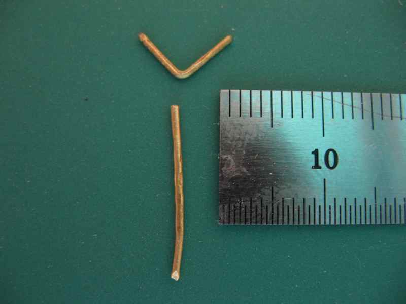
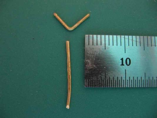
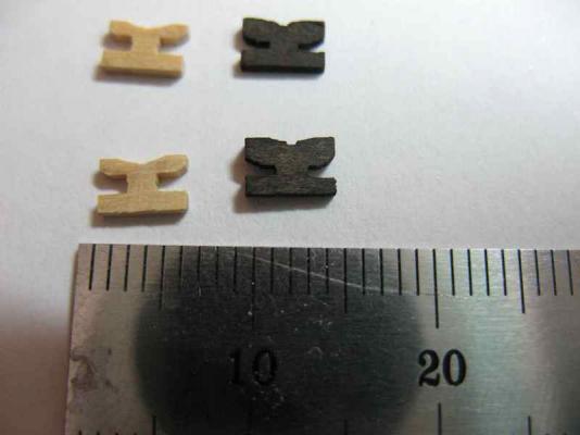
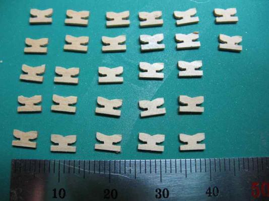
Okay, so I wasn't really happy with the last version of the shroud cleats. I was being lazy and thankfully Mobbsie called me on it - thanks mate! So this morning I had another crack. As I'd already prepared another piece of stock with the basic saw cuts, it didn't take much additional work. I widened the dados in the side, and filed the curves in again. Here's the results of the latest effort (not yet stained black): And here's a comparison of the new (on the left) with the previous version (on the right). I've included a metric ruler as a reminder of just how small these things really are. I think these are much better, but I'd value any and all opinions. Do I go with these, or is it back to the drawing board? I would be reluctant to try and make any parts thinner as I'm already down to 1mm square on the "feet' that will attach to the shrouds. Waddayareckon?

-
:blush: That's very kind of you to say so Sam, but I would be among the first to say that on all the criteria that has been mentioned, the Mamoli kit leaves a lot to be desired. However, at the time I bought the kit (1995), it was probably the best available on the market (not sure when the CC version became available). From what I have seen on this forum, I would have to agree that the Caldercraft/Jotika kit is the best version of Victory currently available. If I we're in the market for one though I'd be hanging out to get a hold of the new a Amati version by Chris Watton. At a scale of 1:64, it might be just a little bit "huge", but just imagine the amount of extra detail and the additional ease of working at that larger scale! Of course, this also assumes that money is no object...........
-
Glad to hear that you not only found something for your Dad, but also that you are now "hooked" yourself! I do hope we'll see build logs for both you and your Dad.
-
Thanks Robert, I think the top surface is okay in terms of when to do it. I'm thinking about being a little more aggressive on the side cuts though. I'll do a test today and let you know how it goes. Glad to hear that I'm not the only one whose head gets messed with thinking about grain direction
-
Beware Patrick - a mutiny may be brewing!
-
Thanks for the comments and "likes" folks. Bug - assembly line is the only way to go for these parts! Working with a larger piece of stock is also much easier than trying to shape these little critters individually. Kevin - welcome back. I've been keeping an eye on your Bismarck, but I'll be looking forward to seeing more progress on your Victory. Mobbsie - you just knew I wasn't quite satisfied with them didn't you? I agree, the anvil is still a little heavy. I've got an idea half formed that I might try tomorrow - now that I've got the basic shape and method worked out, it shouldn't take too long. My biggest concern though is making the horns too fragile. To answer your other question, fixing to the shrouds will be via lashings around the "legs" and also around the centre portion - as per the actual ship fit. That's the intention, anyway.
-
I most certainly do Remco, and this is even better, if that's possible!
-
Fascinating to watch this come together Ed. As usual, a highly instructive log.
-
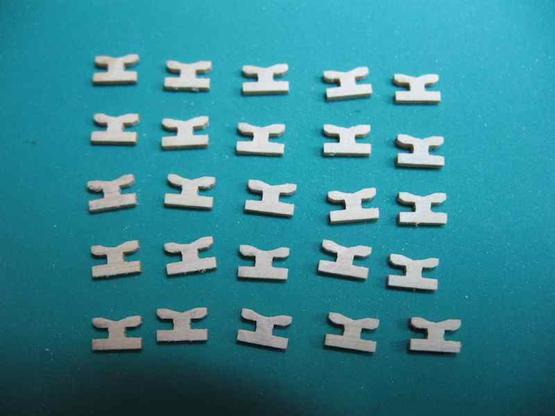
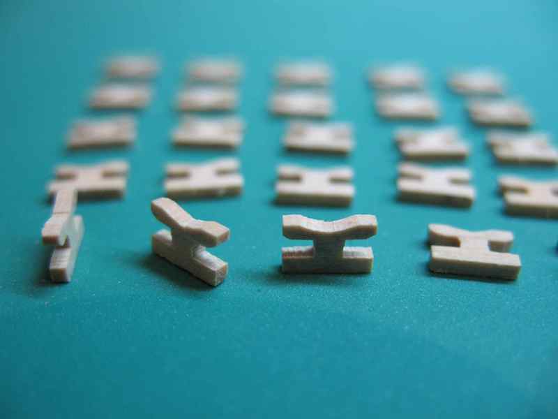
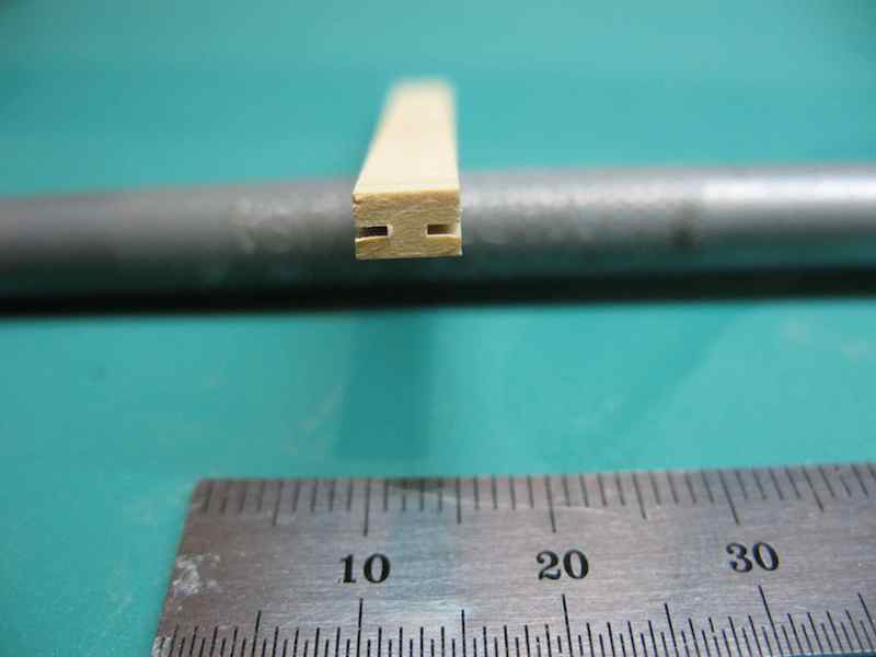
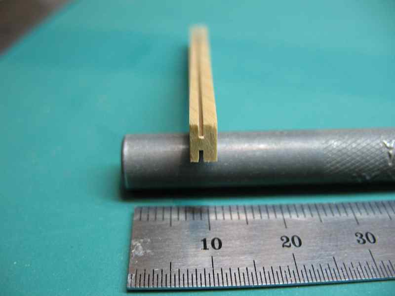
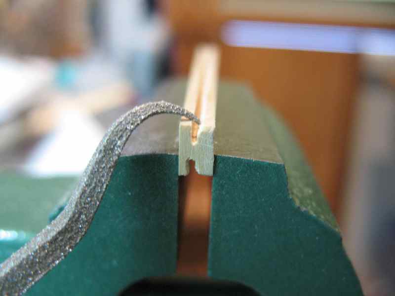
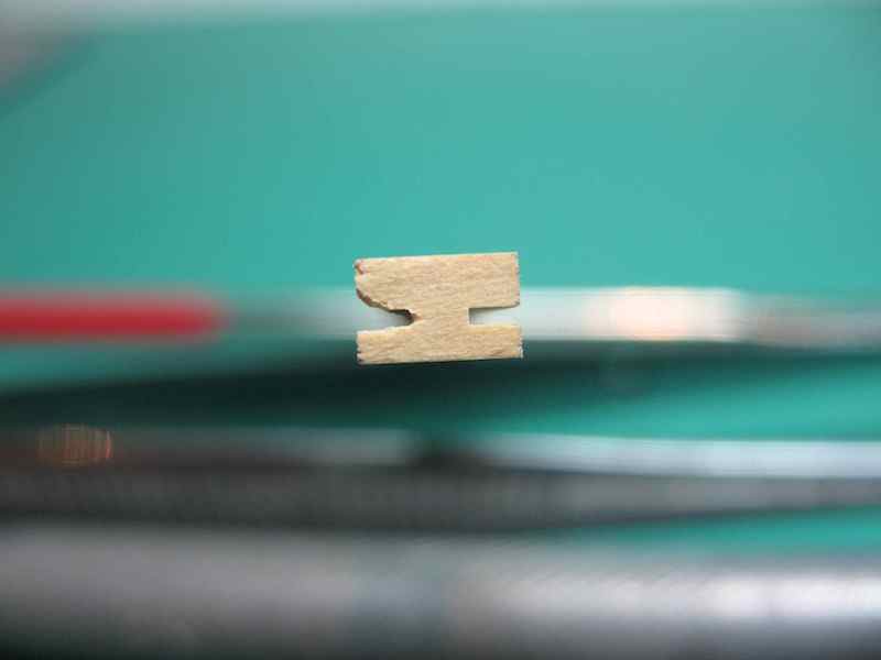
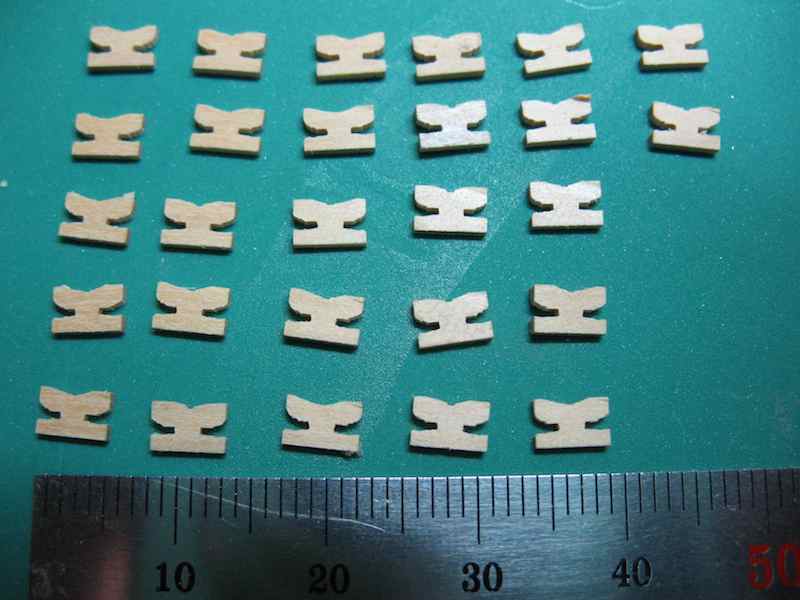
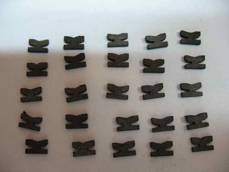
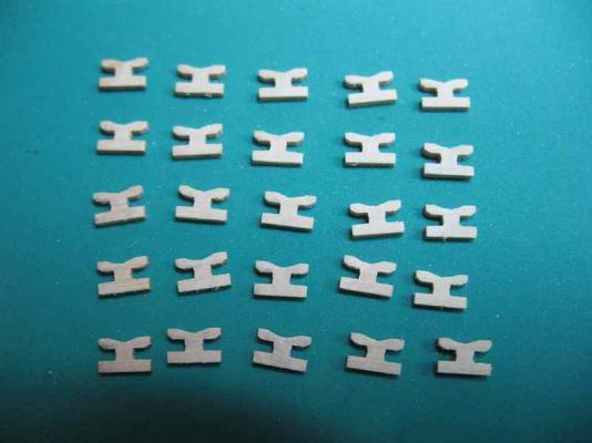
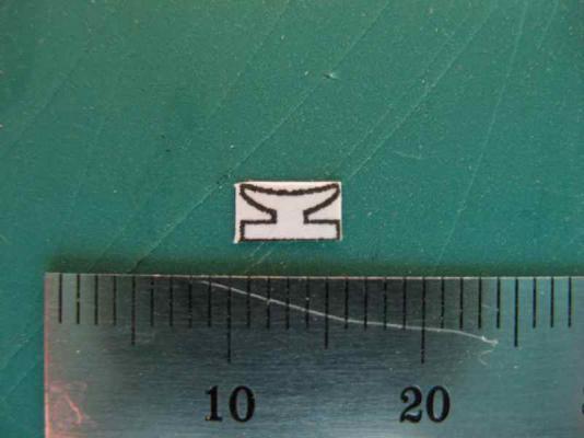
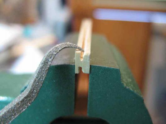
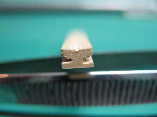
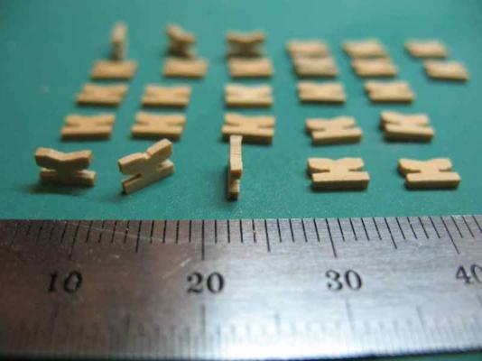
Okay, been thinking about Shroud Cleats for a couple of days and decided that the method described above by Colin was probably the most likely to achieve success (thanks Colin ) First up, I needed to draw something up with dimensions so that I had a clear picture of what I was trying to achieve, so I knocked up a quick diagram in TurboCAD and was fairly satisfied with the overall size, proportions and shape of this: This cleat pattern is 5mm "wide" by 3mm "tall". I had intended to use this as a pattern, glued to the wood to aid cutting, but in the end didn't use it as such. The important thing was the dimensions, which determined the cutting process. The next important consideration was getting the grain direction correct on the finished piece to maximise strength and minimise potential for breakage. For some reason this messed with my head for a while, but I eventually worked it out. Taking a piece of Boxwood sheet 3mm thick and about two inches wide, I cut 5mm wide strips across the grain. This means that in the finished product, the grain will run along the length of the cleat. Then having worked out that I wanted the "feet" of the cleats to have a 1mm thickness for securing to the shrouds, I cut a dado using a 0.020" kerf blade in the Brynes saw, 1.67mm deep on both sides of the strip. These dimensions were important to achieving the final shape. You can see in the above pics that the stock on one side of the cut is thicker than the other side. The next step was to creat the "anvil" shaped horns for the top of the cleat. This was done using some curved riffler files, with the stock held in a small vice. In the next photo, one side of the anvil has been shaped: The stock was then returned to the Brynes saw and a very shallow "kissing" cut was made along the centre of the top side. This was used as a guide for a round file to then shape the curve across the top of the anvil, and leaving a very shallow recess to assist in securing the cleat to the shrouds. In the next pic you can see the final shape, with the curve and recess visible. The last step was to return once more to the Byrnes saw and slice off individual cleats 1mm thick. The hardest part of this process was catching the little buggers as they flew off the saw! Here's the yield from one piece of stock originally measuring 5mm x 3mm x about 2 inches (about 30 cleats all up, a few of which will be further modified to make mast cleats): And here they are, stained black and ready for installation. They still look a little "chunky", but I think I'm happy with them - they seem to be no worse than the metal versions available, at any rate. Now I just have to attach them to the shrouds.


-
How to turn plans into a cad plan?
gjdale replied to SpencerC's topic in CAD and 3D Modelling/Drafting Plans with Software
Hi Spencer, There is an excellent article in the MSW database written by Wayne Kempson on drafting ships plans in CAD (which is what you are asking about, I think). Of course, it requires a CAD program of some sort. There are many available at a range of prices. I use TurboCAD and it seems to work well for a reasonable price. Here is a link to Wayne's article: http://modelshipworldforum.com/resources/plans_and_research/DraftingShipPlansInCADwayne.pdf Hope this is what you were after. -
Good to hear Sean - you'll find Longridge indispensable!
-
Lawrence, Do yourself a favour and use Chuck's line for ALL of your rigging. Sorry Wayne - back to your ship.
-
Looks like you're off to a great start Gary. I look forward to following your progress.
-
She just gets more lovely with each additional touch Danny.
-
That's a great looking sheave block Bug!
-
Mine is probably not the best example to use for a reference Sean - you really don't want to look too closely at some aspects of it! I think if I were in your position now, I probably would put in the bearding line/rabbet - I suspect it will make the hull planking easier/better. With all the advice and support from the knowledgeable folks here, you can't really go wrong. But then again, you're the Captain, so it's your choice ultimately.
-
Looks like a really nice build. Think I'll pull up a chair too - did anyone bring the popcorn?
-
Fantastic Danny. Not only your usual excellent workmanship, but also your customary speed - what else should we expect. Someone is going to be a very happy camper when you finish this.
-
Hi Sean, No, I didn't do a beading/rabbet line - mainly because way back then I didn't even know what one was!!! Your solution to windows sounds similar to mine - I found a product sold by Micromark that paints on like diluted white PVA and dries to a clear solid finish, with that antique glass look. You should be very happy with the results you get from that approach.
-
Another nice touch with the details John. Very impressive build.
- 2,250 replies
-
- 1
-

-
- model shipways
- Charles W Morgan
- (and 1 more)
-
Thanks Colin, I like that approach too. Need to see if I've got some stock of the right size to try that. Definitely worth a go.