gjdale
-
Posts
4,894 -
Joined
-
Last visited
Content Type
Profiles
Forums
Gallery
Events
Everything posted by gjdale
-
 Now THAT is an impressive piece of scratch building ingenuity Remco. But then again, no one here ever doubted that you would come up something brilliant!
- 1,215 replies
-
- 1
-

-
- sloop
- kingfisher
- (and 1 more)
-
Nice idea for the curtains Sean. What did the kit provide for window glazing? Is it still that awful blue celluloid that originally came with my kit, or have they replaced it with something better these days? Or are you going to do your own thing with this?
-
Victory by mikec - FINISHED - Mamoli
gjdale replied to mikec's topic in - Kit build logs for subjects built from 1751 - 1800
I'll look forward to seeing your launch evolve Mike. Scratch building these little guys at 1:90 scale is lots of fun! -
Hi Lawrence, Thanks for your kind comments. Sjors was referring to "another" 10 years from now. This build has now been underway for coming up 18 years (on and off), so yes, I'm keen to get finished and start something fresh. But there is no point in rushing - it will be finished when it's finished to my satisfaction. Only problem is, the longer I hang around MSW, the higher the standard for satisfaction becomes!!! In the meantime, I've found that Cornwall Model Boats, in the UK, stock some Amati 5mm Anvil Cleats (in metal) that look like they will do the job nicely if I can't manage to make something sufficiently usable from timber. So we have a back-up plan!
-
Wow Ed! That's a REALLY brave way to tackle that job! I'm impressed!!!
-
Nice to see you back Rob. Hope you manage to find a little more time for modelling soon. The ship is looking great.
-
Rigging is looking very nice Wayne. Have to agree with you on Chuck's rigging thread - it's a real treat to work with.
-
I hope not Sjors!!! I would like to be completely finished by Easter this year. That will depend on how crazy work gets in the next few months, and how many other little "surprises" I find as I complete the rigging.
-
Victory by mikec - FINISHED - Mamoli
gjdale replied to mikec's topic in - Kit build logs for subjects built from 1751 - 1800
Hi Mike, Looks like B.E. has answered your query on flag arrangements. Re the gun port lids, I added eye bolts to both inner and outer faces of the lid (in addition to the kit supplied hinges). I then used Gil Middleton's splice technique to add the lanyards. These lanyards were fitted in situ on the ship. I did not add the "squiggles" - mine will remain sans squiggles -
Thanks very much for posting those Shroud Cleat photos Gil - they certainly help me to nut this out in terms of dimensions and ratios. So far all the evidence seems to support my hypothesis on dimensions/ratios. I'll have another crack at making some timber ones over the next week or so (back to work tomorrow ) If I have no joy with that, I've noted a couple of manufacturers online offering 5mm cleats - but that will be a last resort! Thanks again for all your time and trouble to help out a fellow modeller - the very essence of MSW!
- 755 replies
-
- 1
-
-
- finished
- caldercraft
- (and 1 more)
-
Thanks Bug - no need to rush! You're doing a fantastic job on your Santa Maria - just enjoy that for now. The 18th Century vessels will still be waiting for you when you're ready. Mark - I did consider that, and even tested a couple, but wasn't satisfied with result. I'll have another crack in a couple of days. Seconded to domestic duties today and back to work tomorrow
-
Hi John, I'd agree with the others re blackening brass in situ. Apart from pre-cleaning/degreasing, you will also need to be able to thoroughly rinse the parts afterwards to halt the chemical process. If you were to use copper wire instead, you could blacken in place using Liver of Sulfur, which is much easier to clean up afterwards and won't affect any surrounding wood. Not sure if copper wire would be strong enough for your purpose though. Paint might be your best option here.
- 2,250 replies
-
- 1
-
-
- model shipways
- Charles W Morgan
- (and 1 more)
-
Sounds like this really was a blessing in disguise Robert! That beautiful piece of a Cherry was "meant to be" for this project - you just needed to do some practice before cutting into the really good stuff.
-
Thanks for the pictures of the cleats Mobbsie - looks like those measurements also support my hypothesis. Thanks John for your observation too.
-
Thanks Lawrence - most kind of you to say so. Thanks B.E. for the extra photos. As far as I can tell they would seem to support my hypothesis on size and ratios.
-
Thanks Mobbsie - that's great. Sounds like Jotika/Caldercraft have used the same approach for Aggy as for their Victory. The pictures are a big help in terms of placement. Did they provide you with Shroud Cleats for Aggy?
-
Thanks B.E. - much appreciated.
-
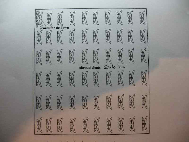
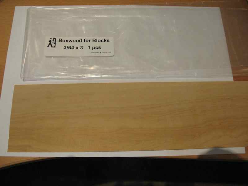
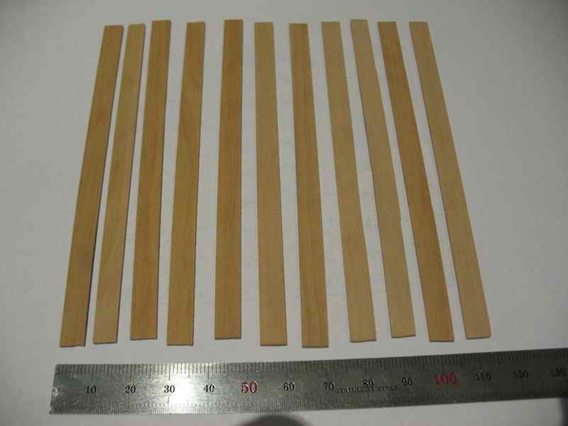
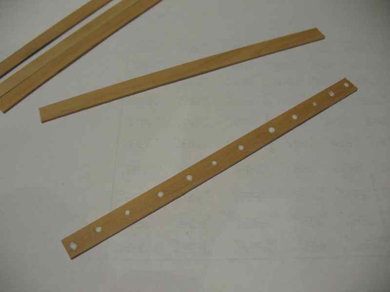
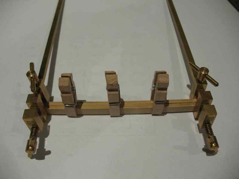
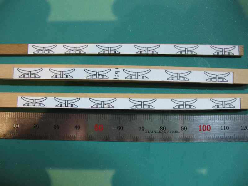
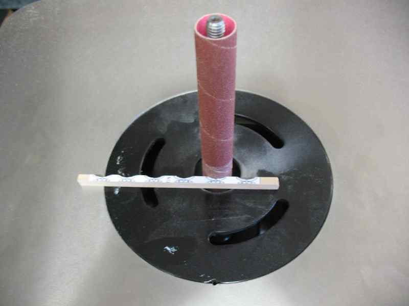
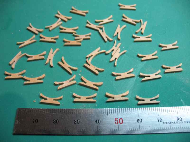
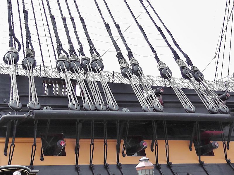
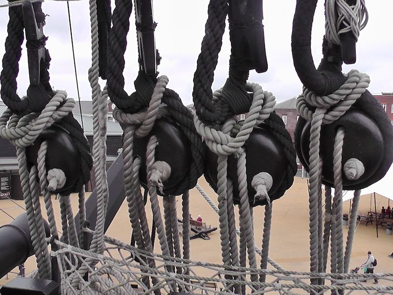
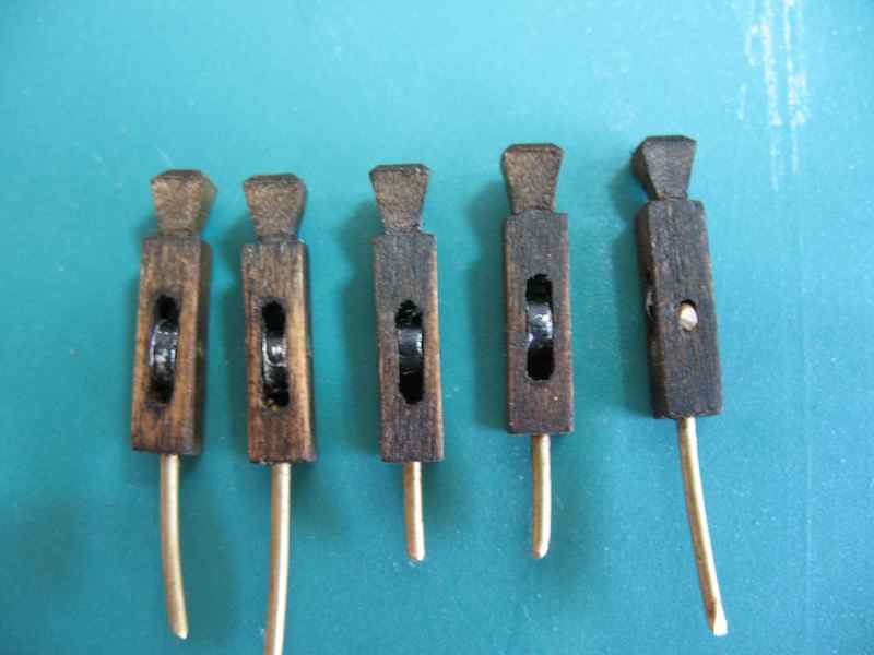
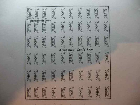
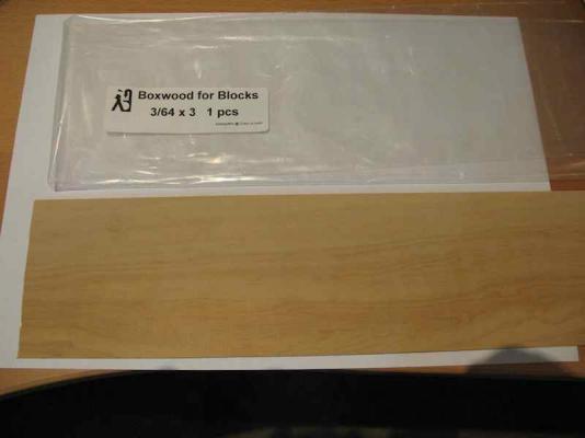
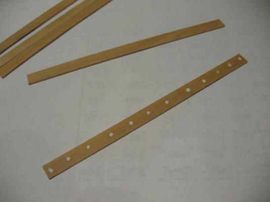
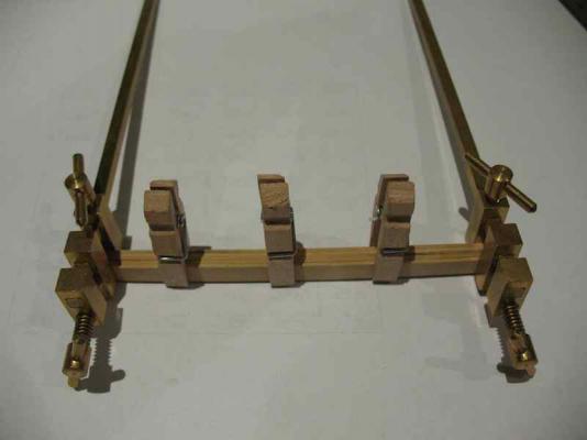
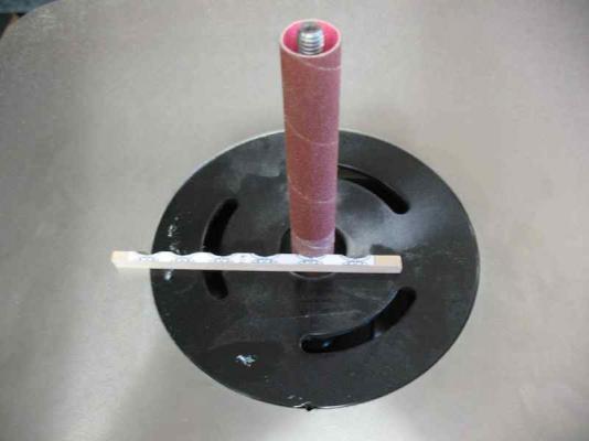
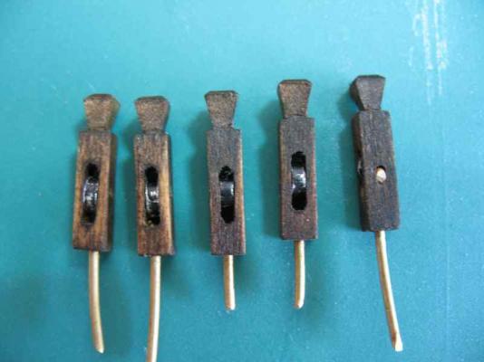
Okay, now the not so good news - Shroud Cleats. Again, something I picked up reading through Gil's log, and again conveniently neglected in my kit. Longridge is again scanty on information, once again giving a sketch diagram with no dimensions and stating simply (pg 215) that: "Shroud Cleats have two arms, or horns, like an ordinary belaying cleat and the base is grooved to fit onto the shroud; scores are cut on the base for the seizings which lash it to the shroud. They are made in several different sizes from 18 inches to 8 inches and are attached to the inner side of the fore and mizzen shrouds." Another PM conversation with Gil, in which Gil advised me that, not being satisfied with the Jotika supplied cleats he used ones from the ME Constitution kit and modified them slightly to suit his eye. Unfortunately, that meant I couldn't simply copy his method. Having thought about if for a day or so, I came up with a cunning plan......or so I thought..... I found in my Warrior Practicum (Romero) the pattern for shroud cleats for the Warrior, in 1:64 scale. "Beaut!" says I - all I need to do is to scale those down to 1:90 scale and I've got a useable pattern. So off I go. Now, I recall reading in Robert's HMS Mars log recently, how he'd made these beautiful gun carriages but hadn't made a prototype before going into mass production, with the result that the end product didn't fit the guns at the right height, thereby entailing a significant amount of rework. I should have listened.......but we'll get to that! So here's my starting pattern, neatly scaled down to 1:90. Thinking "mass production", the plan was to cut strips of stock and glue them up in gangs prior to cutting/shaping. So, into the stash of lovely Hobbymill Boxwood - using 3/64"thick sheet stock to roughly match the diameter of the shrouds. And cut into 1/4" wide strips, approximately 4 1/2" long on the Brynes Saw: Then spot glue gangs of five strips using the smallest amount of glue possible to facilitate easier separation later: And clamped and left to dry overnight: The pattern was then cut into strips, with each pattern strip carrying six cleat patterns, and attached to the glued up gangs: After trimming up to the "flat" edge of the pattern on the Brynes Disc Sander, the "curved" edge was achieved using the newest acquisition - the Oscillating Spindle Sander. This step could have been done with a Dremel and sanding drum, or even by hand with a half round file. But I do like my toys, and this one is ripper! The final cutting shaping was done with the scroll saw, and the pieces then given a bath in isopropyl alcohol to debond the glue and separate them. Here is the final (unsatisfactory) result : Apart from some dodgy cutting by the scroll saw operator (stop his rum ration for a week), the overall method worked very well. What I'm really not happy with is the overall size/proportions - they look far too long and flimsy; grossly out of proportion for the ship. I went back and checked the Warrior Practicum, and relatively speaking, they are the same proportion (a photo in that book shows the cleats spanning three ratlines - it just doesn't look right). So, back to the drawing board. I went back over some photos that dear Sjors and Anja had sent me some time ago and I found these two photos that show a little of the real thing: From what I can make out from these, the overall length of the cleats seems to be just a little longer than the diameter of the deadeye on that shroud. Given that my deadeyes on the Foremast shrouds are 5mm, an overall length of about 6mm would seem about right - that's about half the length of my failed attempt. The length also appears to divided into roughly three equal segments - one third each for the arms (or horns), and one third for the middle section. The overall front to rear "depth" dimension is difficult to tell from the photos, but I'd guess that it is about one half the length, which would make it 3mm for me (again, half the size of my fist batch). The thickness would stay the same, as that matches the shroud diameter. With those reduced dimensions, my sense is that the cleat would not look (or be) nearly as flimsy, and would look about right in terms of overall size compared to other aspects of the model (e.g. the deadeyes). Again I have no other reference than some guesswork based on Sjors's photos. Even Lees does not give any further direction on dimensions. So, once again, any and all opinions on the overall dimensions and ratios as I've described them here would be most welcome. Oh, and I'll make a cardboard prototype this time around!


-
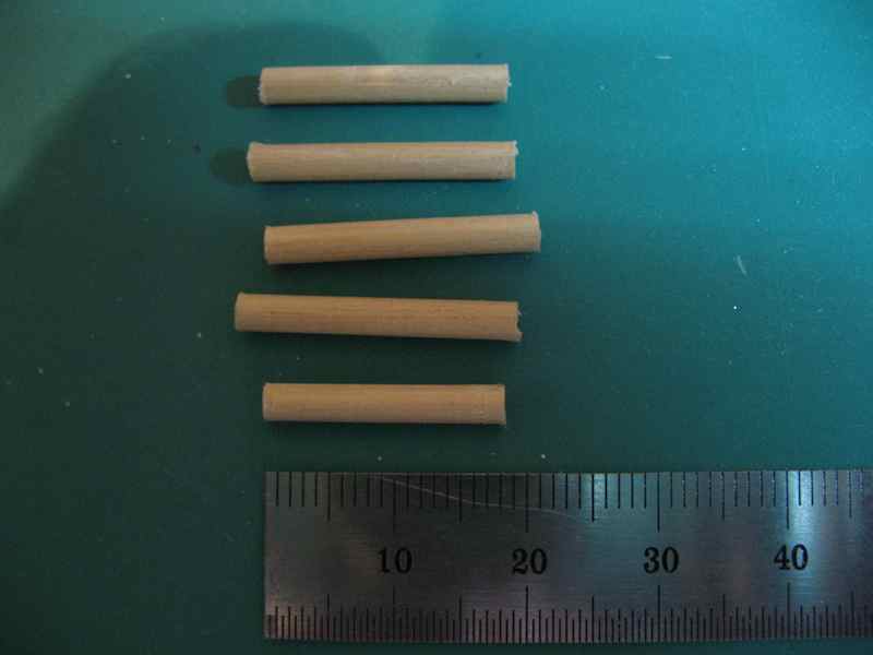
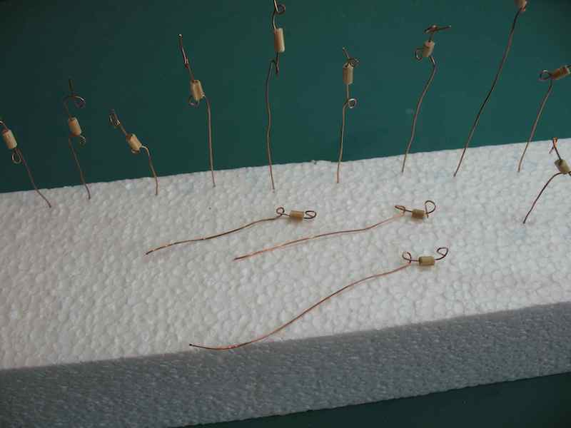
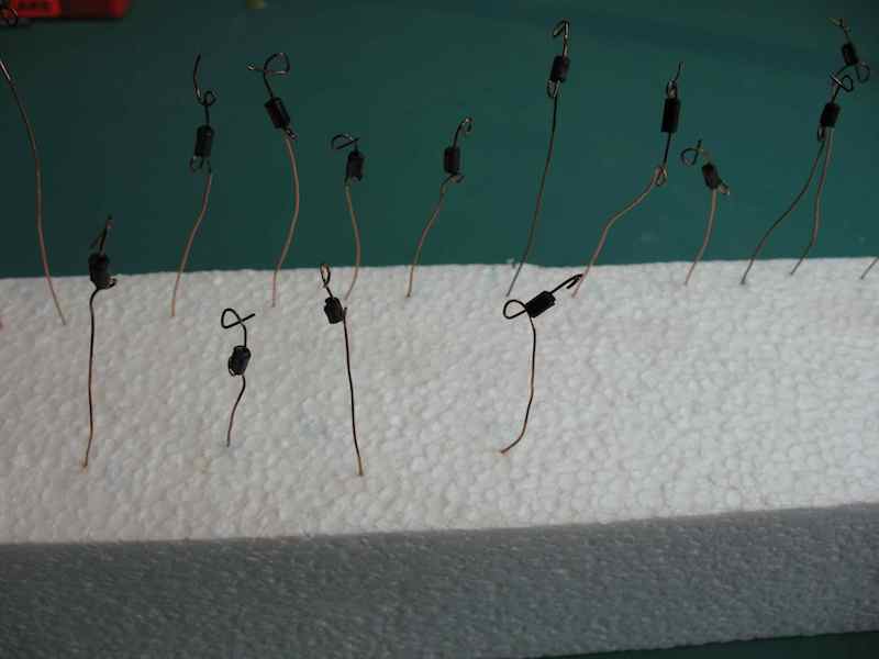
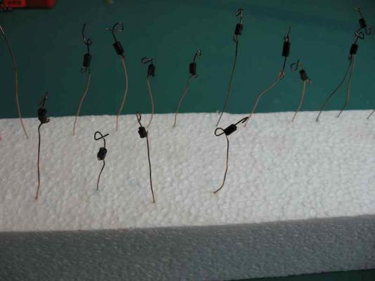
Thank you one and all for the various kind comments and the "likes". I appreciate each and every one of them. So, you know how I said "now I'm ready to continue re-installing the yards"? Hmmmmm.......... might have been a bit pre-emptive with that. Four words: Shroud Trucks, Shroud Cleats. More on that in a moment. First of all, the Kevel Blocks are now completed and ready for installation: Note the brass pin to be used for insertion into the deck. These will be glued in with epoxy. I'm quite please with the way these turned out. So, I was just going back over Gil Middleton's log to see if there was anything else I'd missed and to steal shamelessly any good ideas he had while I was at it. There I came across the Shroud Trucks - conveniently omitted by my kit. Longridge is very scant on discussion of these, giving a sketch diagram with no dimensions, and saying only (pg 215) that "... Trucks are small short cylinders of wood with a hole bored through the long axis, and a score on the outside also on the long axis. They are lashed to the shrouds and various lines are led through them." He doesn't even say which lines. So I've had a bit of a conversation with Gil via PM and he advised that the Jotika instructions say to pass the Topmast Tyes through the shroud trucks on all three masts, though he opted to do so only on the main and fore masts. Gil's method of making trucks is posted on his log (pg 7, post #100 if you'd like to check it out). He used styrene tubing and presents a nice diagram of how he approached it. Having thought about it, I decided to have a crack at making them from wood. Using Gil's styrene O.D. as a guide, I started with some 3mm diameter dowel and cut them into roughly 20 mm lengths. The final length of each truck was to be 4 - 5mm, but working with a slightly longer piece to start with makes life much easier. Then, using a micro chisel with a round end, I cut the score on the outside of the long axis (this is where it will sit against the shroud, so the shroud will seat into the truck). Here's another view after the chisel work: I then bored a 0.8mm hole using the Proxxon Drill Press (did I mention I really like this little tool ) Then I cut the 20mm length into four roughly equal segments, and chamfered the ends with a light touch of a file: These are to be stained dark brown, so to make that process easier, I gave each one a "handle" of copper wire with a couple of twists to stop it from falling off. The idea is to "dunk" the truck into the stain like a tea bag. After dunking, the trucks on their handles are returned to the polystyrene block to dry. Again, I'm quite happy with the way these turned out. I'm still not sure how many I need. Although Jotika say to only pass the topmast tyes through these, it would make sense to me that any line that is tied off to a shroud cleat would first pass through a truck. Going from Longridge's belaying plan, that means I would need a total of 24 tucks. I've no reference for that, so any and all opinions on the subject are most welcome. Next up - Shroud Cleats.


-
Sorry to hear about the setback Robert. I'll bet that's a lesson you won't forget in a hurry though! Good on you for your perseverance to get it right. I'm sure you will be very happy with the final result.
-
Paul, Just be aware that this kit is smaller of the two versions that Mamoli offer. This one is 1:150 scale. Their other one (which I'm building) is 1:90 scale. If you want to go with a larger version, I would suggest saving your pennies and going for the Jotika / Caldercraft version (1:72 scale). It's arguably the best Victory kit on the market at the moment. There are plenty of build logs here to see this kit, but if you check just one, have a look at Gil Middleton's log - it's probably the "Gold Standard". Or, if you wait a little longer yet (and save even more pennies), Amati are about to release a new version designed by our very own (MSW's that is) Chris Watton. It looks to be a real beauty!
-
Hi Derek, I've been quietly following your progress for some time but haven't left a comment before. Please allow me to rectify that right now! You're doing a terric job on this build. You have my absolute heartfelt sympathy on your bowsprit mishap. I recently had a similar mishap with my Fore a topgallant mast. And I've knocked the bowsprit so many times I'm surprised it hasn't snapped on at least a haf dozen occasions! Still, as you've just discovered, these mishaps do set us back a little, and most certainly expand the vocabulary of those within earshot at the time, but they are repairable. Keep up the great work.
-
This a lovely little project J. I've become quite enamoured of this little boat, and so have just acquired the plan set to add to my ever growing "one day" scratch build list. They arrived in the mail today I'll certainly be following along with your build from here. Keep up the great work.
-
Hi Ben, I somehow missed the start of this build log, but I'll pull up a chair in the front row and follow along from here. Looks like you're off to a great start.