Ian_Grant
-
Posts
2,156 -
Joined
-
Last visited
Content Type
Profiles
Forums
Gallery
Events
Everything posted by Ian_Grant
-
 Actually I read that the newer Revell Wasa kit is fully up to date. It looks beautiful; I nearly bought one but my stash was already a size for the years I have left!
 -
Yeah, the area behind the foremast is a particular problem because it is boxed in by shrouds on each side, and many lines running up from the forecastle after railing to those blocks you mention under the fore top. To make it worse, there are also some lines running for the bitts aft of the foremast, up to blocks under the main top. For the fore top, look at Longridge Plan #8. Reading the lines passing through the blocks from left to right, we have the course leech, spritsail brace, two course buntlines, and the sprit topsail brace. On pg 266 we see these all originate from beside the belfry (in the same order to avoid criss-crossing on the way to the blocks). To estimate the lengths needed, the leech line goes out to the foreyard end, the buntlines go to intermediate locations on the yard, spritsail braces go to the ends of the spritsail yard hanging below the bowsprit, sprit topsail braces to the ends of the sprit topsail yard hanging beneath the jib boom. I rigged without sails and so just passed the leech and buntlines through their blocks and hitched to the yard. If you plan sails, they'll need to reach the leech and the foot of the fore course. Plan 7 shows all of these lines and buntline block locations on the yards, albeit in a busy way. As for the main top blocks, the main course bunt lines, two each side, originate at the bitts aft of the foremast (see pg 266 and Table pg 269), pass from forward to aft through the double blocks under the main top, then go to buntline blocks scattered along the main yard. You can estimate the lengths. The main course leech lines have tackles with the fall belayed to the bitts aft of the main mast (pg 267, Table pg 269); Longridge mentions deck ringbolts aft of the main mast (pg 251) and checking on my model I see I added two more eyebolts for these, one each side of the pair you already added for the mizzen stay and preventer. Sorry I forgot these! I used a ruler to add up all the distances traversed by each line, added a little extra, belayed on deck, passed through the bocks then coiled until needed (see my pic in post #742).
-
Marc, it's because the kit includes the patented Heller shroud/ratline jig. The masthead mounts at the top corner, and depending on which mast it's for you wind threads around labelled notches and put dabs of glue at the intersections. Then you mount the masthead and shrouds. I didn't use it.
-
Actually Revell has a kit for Thermopylae. I think it's mostly a rebranded Cutty Sark but maybe there are differences? You can find it on ePay.
-
Bill - are you sitting down? I believe I rigged about 310 blocks on Victory and that's without sails....🤪 and don't forget deadeyes I just made a quick rough count at 224. OC - my wife used to shake her head when I showed her the details I was working on, and that's exactly what she said it must be 😃
-
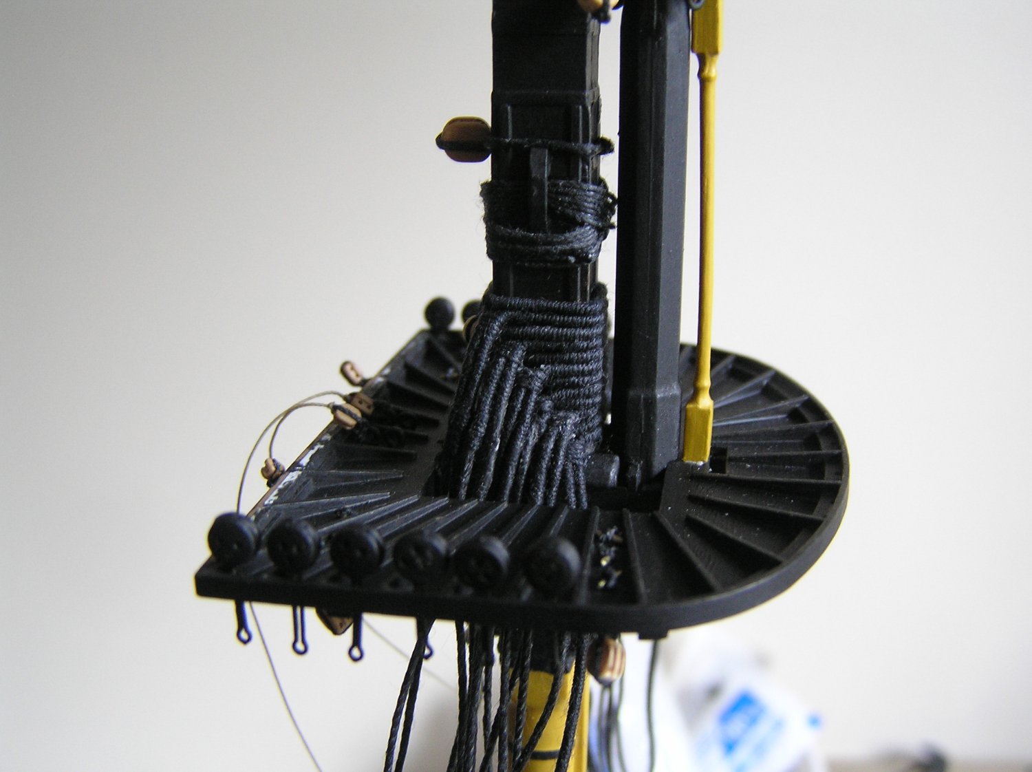
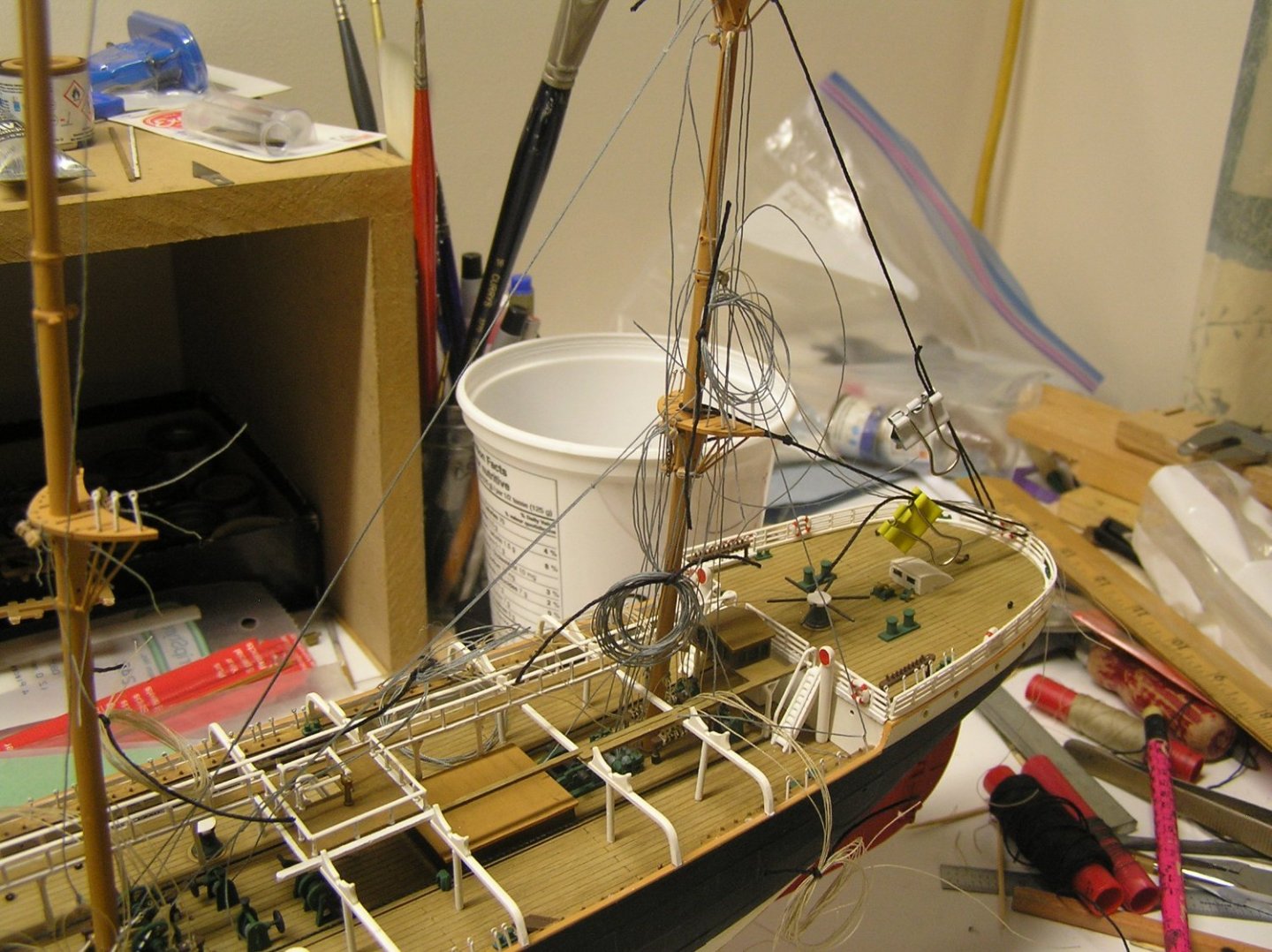
At long last I have added the lower and topmast stays to the jigger mast. I braced the jigger from aft to allow these to be tautened in the correct position. I've also coiled up some groups of lines to reduce the mess somewhat. I like the look of the "rigging screws" on these stays at the foot of the mizzen. Here we see the pump added afterward. The large holes remaining are for two brace winches, not yet rigged. Once all the blocks are on the mizzen it can be glued in. Here we see the machinery at the foot of the jigger. The port lower capstay is threaded through its rigging screw at the lower right. I got that far and realized I have not figured out what to do with all the shrouds and backstays. You know how all the ships seem to have several seizings all painted white? They need to be between the ratlines which are spaced at about 1/10 inch in this case. I need to find some un-fuzzy white thread because I don't want to fiddle with paint here. Need to make a clip-on paper template to plan ratline locations and hence locate seizings. Here is where the chickens come home to roost, because I did not get all the rigging screw heads accurately aligned.


-
A quick note Bill; the topmasts can only be pushed through the cap from below, as I recall. You must have them in place when you glue the caps.
-
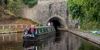
Just reading on-line about the canal. Sounds fun! I smiled seeing the Chirk tunnel; recalled to mind Hornblower helping to "leg" a canal boat through a tunnel on his way to assume command of "Hotspur".
-
Last time we were in London we boarded a narrowboat and voyaged through "Little Venice" and past the zoo to Camden Market for lunch. Great fun!
-
High of -9C (16F) today, down to -20C (-4F) tonight. Warmer on Sunday then back to cold. It's been a very poor winter so far; not much cold weather and very little snow. The Rideau Canal has not frozen enough for outdoor skating yet and the x-country ski trails are short on snow 😭. I was out yesterday and the tracks are very glazed due to recent thaws; makes for great downhills but hard on the grip wax. Sigh. They forecast a "large snowstorm" last weekend which missed us. We are apparently set to just miss another. Sigh again. But yes, I can get some work done on Preussen.

-
Just from modelling and reading I'm afraid. I've never sailed anything bigger than my dinghy (Bombardier Invitation) other than steering "Royal Clipper" one evening.😀😀😀 (Definitely a bucket list item!!). If I appear to be an expert on "Victory" it's because I have Longridge semi-memorized 😉. Sharing is what this site is for. I love seeing other models coming together, especially Victory, and hope to help others spend less time than the hours and hours I spent just thinking as opposed to rigging!
-
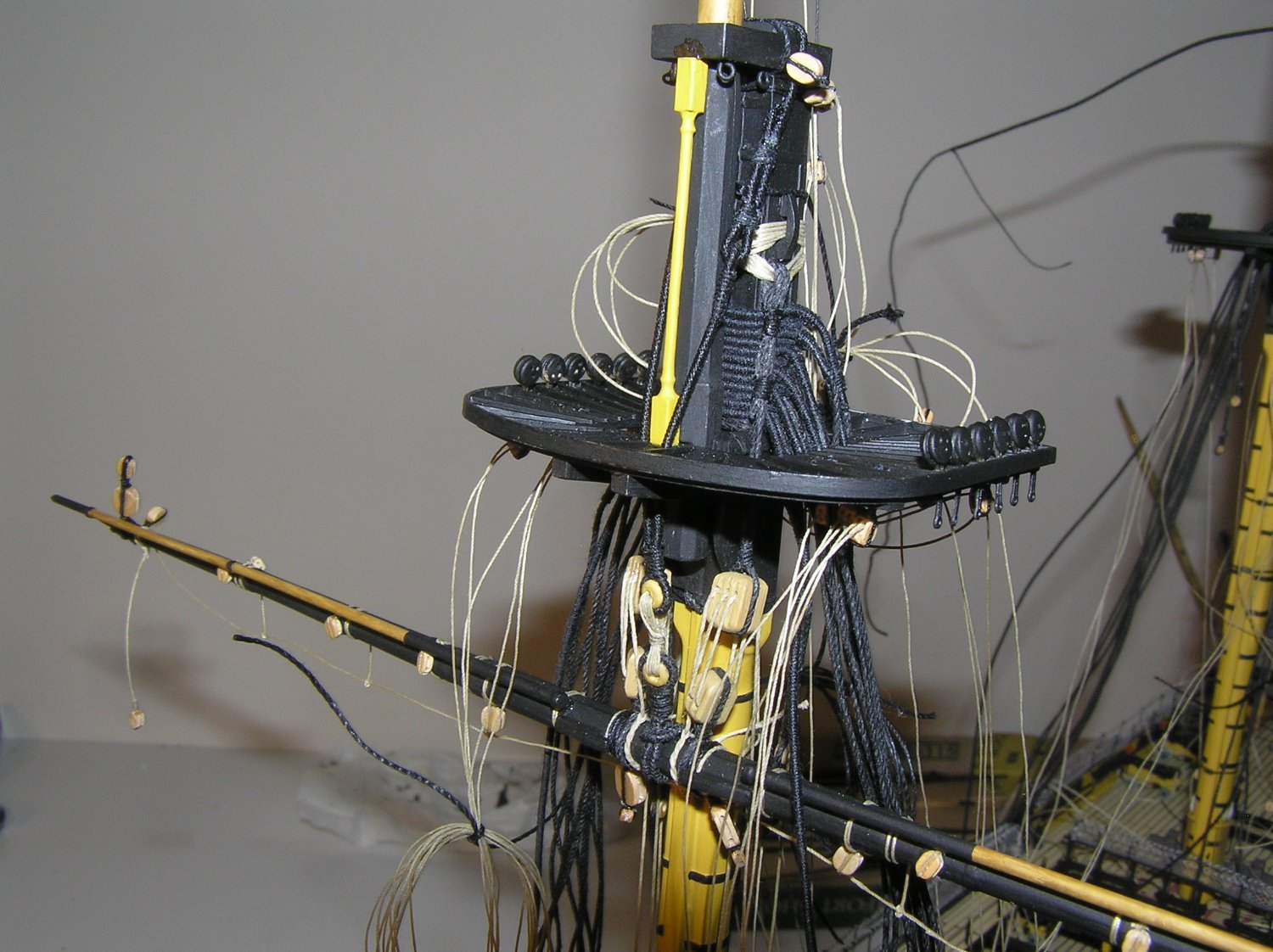
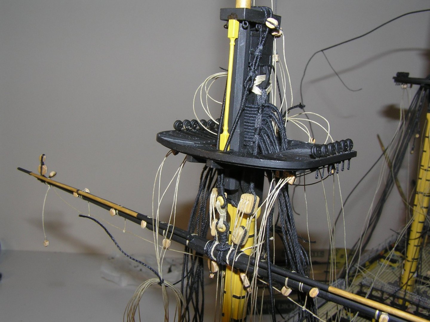
I looked through my old pics to see again what I did. Here is a photo from early 2017. The jeers, sling, and truss pendants/nave line are rigged before the shrouds had deadeyes, for access. My thinking was that any mast movement when aligning it with stays and shrouds would not affect, ie slacken, anything just running up and down the mast anyway. Also seen are all the buntlines, clewlines. sprit braces etc that pass under the top, already tied down at deck level to rig in reverse. Of course, the yard was equipped with all blocks and footropes before mounting it. I forgot to lash the boom ends, so I just never did. As an aside, I started running into the "server error 200" while attempting to upload pics yesterday. This pic wouldn't upload either so as suggested in the "server error 200" log I submitted this reply with text only, then clicked "edit" and tried an upload again, which worked obviously.
-
At all 3 masts, there are two deck eyebolts and two cleats on the front of the mast labelled for the truss pendants. Referring to Longridge pg 240, you see the diagram of the pendants themselves ending in double blocks.Two more double blocks are hooked to the deck eyebolts. The pendant tackle starts at the eye at bottom of the upper double block, reeves through the upper and lower blocks, and the free end (the "fall") is tied off to the cleat. So you are using all four of the marked positions, in the case of the mizzen #78. It's a similar story for the driver boom topping lifts #93. Referring to Longridge diagram pg 255 and text pg 256 "Topping Lifts", the topping lifts themselves end in double blocks. This is rigged in a tackle with a block at the deck eyebolt, and the fall is tied to a pin on the mast ring. You can see this in the Figure, the 15" double and 15" single aligned at the lower right. Thus again, all four positions marked 93 are used. Now that you are at the rigging stage I recommend you read and re-read Longridge and make notes. That's what I did to keep track of all the blocks and tackles.
-
Deck seam looks great! Well done Kevin. Between you and Bill, you're going to make me want to restore my old CS in ordinary.
- 444 replies
-
- 2
-

-
- Cutty Sark
- Revell
- (and 2 more)
-
Me, I would attach blocks to your eyebolts below the tops then glue the tops on. You can't really rig the lower stays before the shrouds as the stays are laid over all the seized shroud loops round the mast. You'll have to seize your shrouds round the mast in situ since the lift blocks and jeer cleats negate forming them off-model then slipping them over the mastheads. Damn I should have mentioned that before 😬..... I actually broke off the jeer cleats to let me do exactly that. Sorry! Remember too that the pendants go on before the shrouds..... But before you do anything I recommend you attach the relevant stays (with thimbles and lashings) to your new eyebolts behind the fore and main masts. Get in there while you still can, coil the stays and rig in reverse later. ps Shouldn't there be two eyebolts in front of the mizzen, and indeed the others, for the pairs of truss pendants? Looks like only one ahead of your mizzen. If you want to be really accurate you can bust out your new serve-o-matic machine and serve the centre portion of each shroud pair (consult Longridge) before seizing the loop. Here's a pic of my first served shrouds, at the foremast.

-
Bill, not to distract from your Victory but I'm curious about Kevin's comment...😉 Kevin, have you 3D printed a deck for CS? I ask because as far as I know the Revell CS still has that annoying deck with the caulking lines molded proud of the planks, rather than recessed. Or were you trying to paint only them? With a properly molded deck it's easy to paint a wash over all, then wipe off leaving it in the cracks. Wish I had known that for my Victory instead of using ultra-fine-tip markers. Now back to our regular scheduled program........
-
Very interesting model,Claire! My two cents: additional horizontal strips on the exterior grid would add shadow lines and depth and look striking. They don't need to be very thick if you're worried about the bulk. Just my opinion....
-
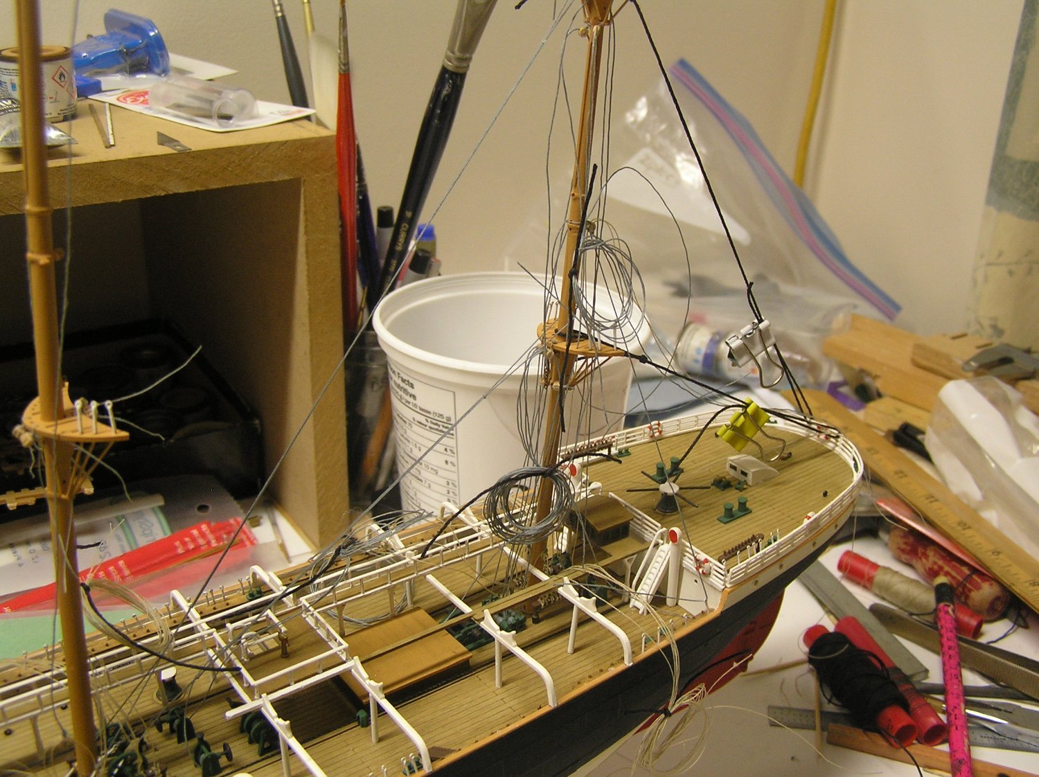
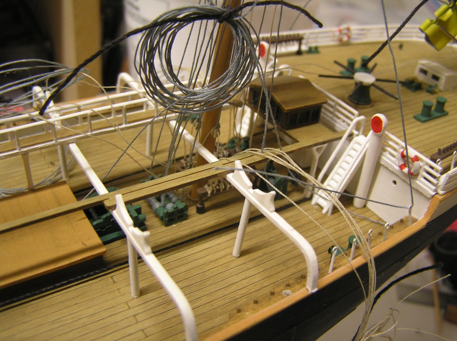
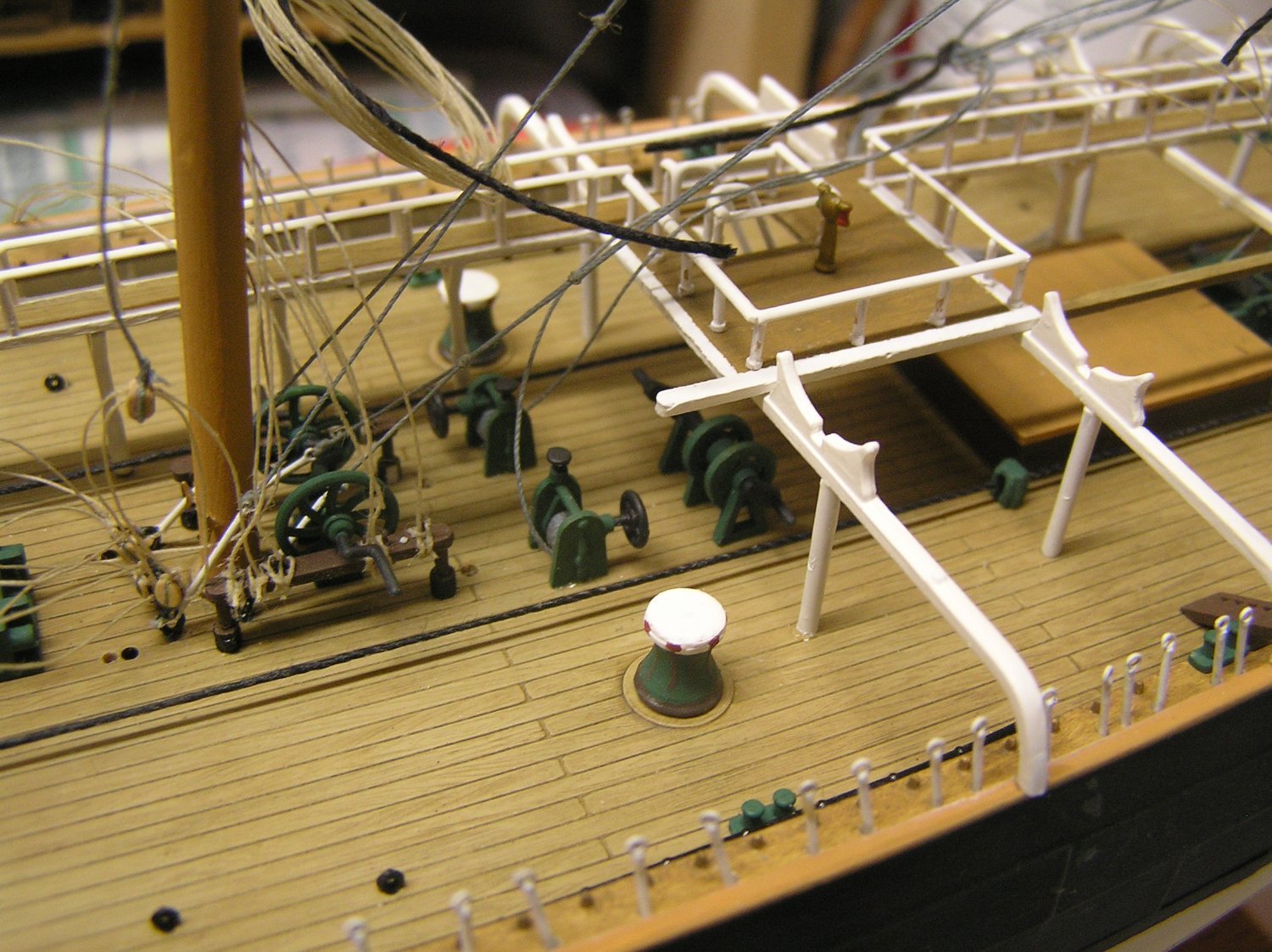
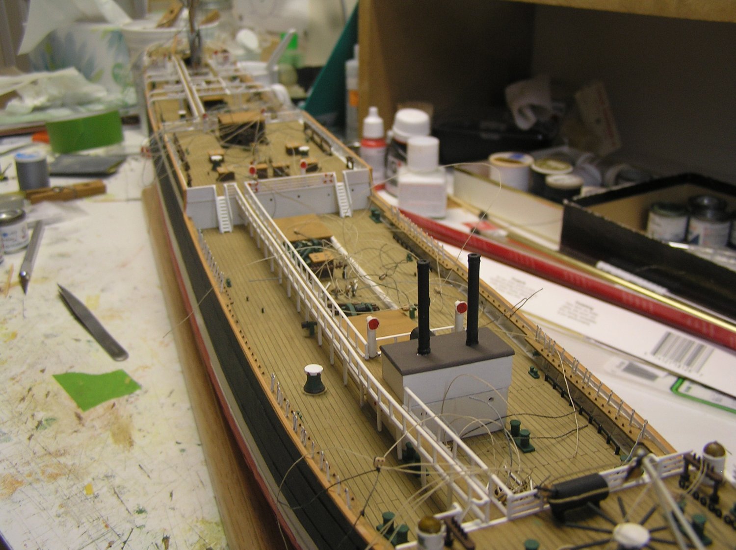
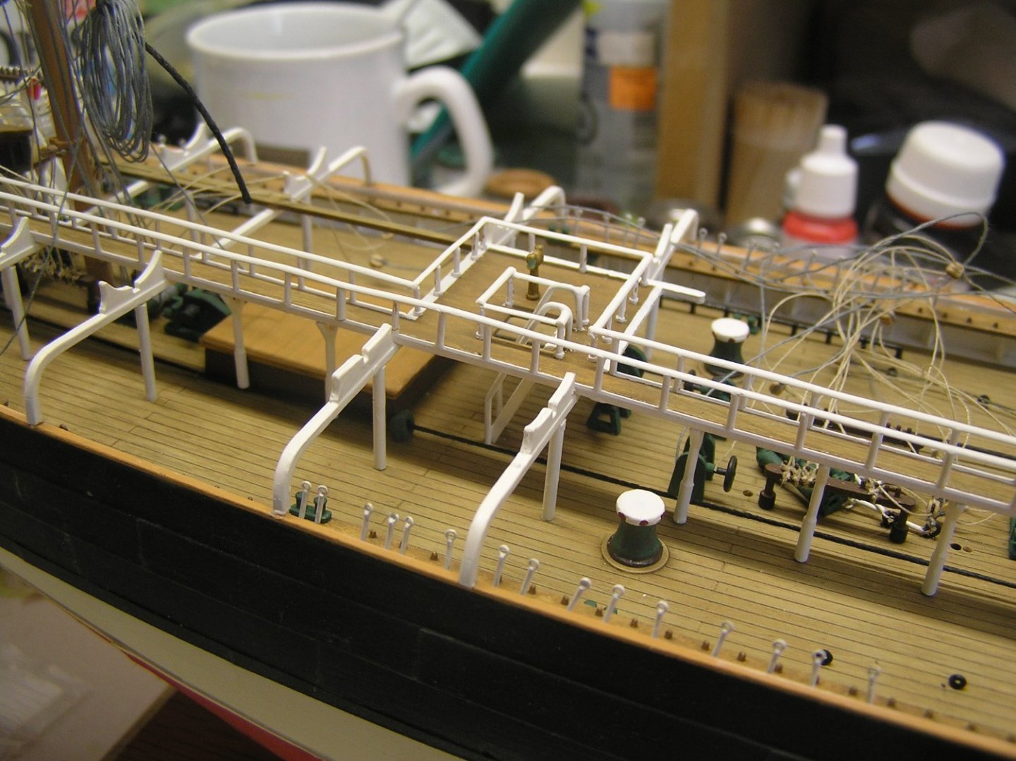
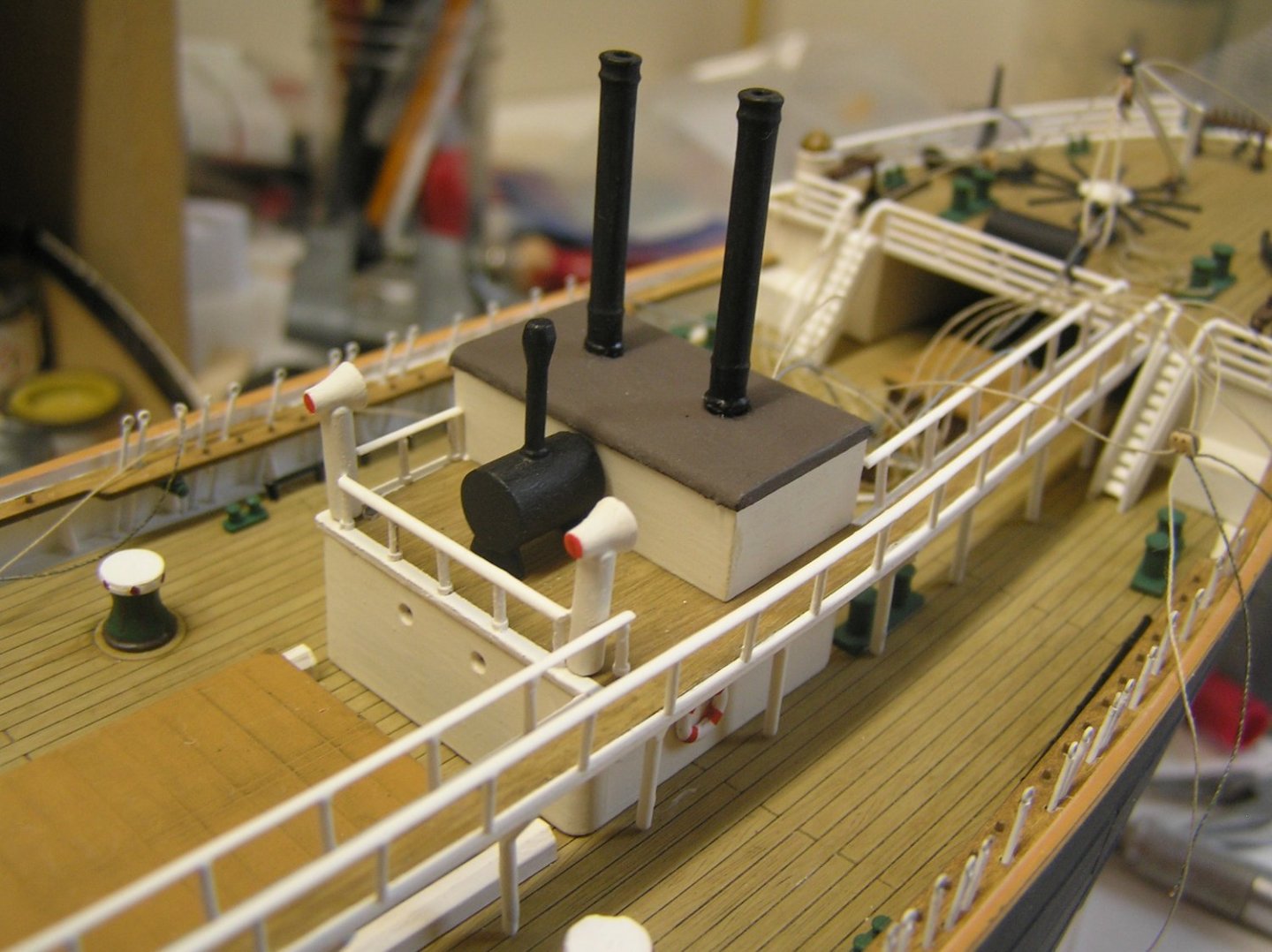
Got the handrails (evergreen .040" half round) on without too much bother. Once you get one end started it is easy to CA the tops of the stanchions 4 or 5 at a time. Also added the ladder and its brass handrails to the flying bridge, and the 2nd compass. All five masts now have the four whips for the lower topsail sheets and lower yard lifts in place. I noticed the boat chocks are not really the proper curvature to match the boats but at this point I am not going to risk damage by trying to file them. Oh, and I have now knocked off and re-glued the starboard chimney of the boiler hut. Twice. I think I am at last ready to go full into rigging mode. 😃🤓 ps Had a 3rd pic but it won't upload despite several attempts (server error 200???). LATER EDIT: It seems a fix for this is to submit your post, then immediately "edit" and upload the picture again. Worked for me this time, so it's added below.

-
Veszett, it's all good! Anything windjammer 😄.......That's a great documentary - they actually screened it one night for us when we were aboard "Royal Clipper".
-
Bill, it's not you it's the kit. There is indeed an alignment problem with the mainmast hole in one of the decks; I forget which. I recall testing it after adding each deck and going at it with a file too. Too bad about the pikes - at least you had the fix method previously worked out! 😀
-
EJ - do you mean you have built SR twice now, or that you've done gilt or coloured sculptures on various models? I'd love to see some pics of ships with painted ones.....
-
I hadn't noticed that about the railing yet. You're right, if it extended straight from foc'sle to 1/4deck it would make sense. Maybe I will add another handrail there when /if I get to that stage. The other thing mystifying me is access to the poop and "flying poop" (or whatever they call it). I can see maybe an internal companionway to the poop deck under the poop deck cabin, but how does one access the flying poop? I could have worded that better, perhaps. 😀
-
Another Heller Victory kit build! All right! Welcome George! There are a few of us here; I hope you start a build log. The Imai instructions are nice. If you need a rigging reference, Longridge's "Anatomy of Nelson's Ships" is one of the best specific to Victory. Regards, Ian