
Baker
-
Posts
4,130 -
Joined
-
Last visited
Content Type
Profiles
Forums
Gallery
Events
Posts posted by Baker
-
-
-
-
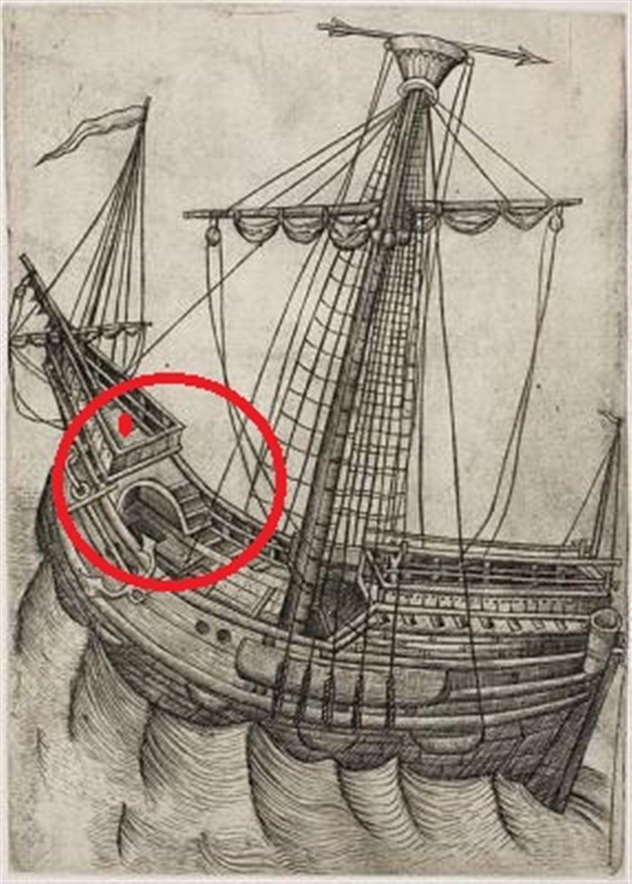
13 hours ago, Alvb said:
I'm a bit skeptical. Why such an impractical route? First, somehow get to the bow, and then take this dangerous route to the next deck.
7 hours ago, Kenchington said:I think I'm with @Alvb on this.
Sure, if a fit, young seaman can get from the topgallant yard to the deck by sliding down a backstay (and that was done, at least in the last decades of the big windjammers), then he can take a run at the forecastle and try to get up a sloping surface of planking (even though lapstrake could hardly be better designed to deny finger and toe holds!). But that just doesn't seem to be a practical route for everyday use.
Also:
You don't need any space for vertical access between decks. All you need is some steps, either cut into the corners of a vertical structural timber or else nailed onto its sides. Anything will do: The foremast itself, the knighthead for the foreyard tye or anything else, so long as it spans from one deck to the next above. And you need a scuttle in the deck above, of course, for a man to emerge through.
That sort of crude ladder was normal for getting into and out of the holds of later sailing warships, even when (quicker and more convenient) stair-like companionways were fitted in high-traffic areas.
Trevor
As with many things for ships from this period.
There's no evidence that there was a ladder in the forecastle.
And there's no evidence that there wasn't a ladder in the forecastle.
And anyone who fell off board or from the mast, or had another accident, was simply unlucky.
- davyboy and GrandpaPhil
-
 2
2
-
-
3 minutes ago, Alvb said:
What is the basis for the theory that the arches served as access?
On the interpretation of these drawings?
Drawings.
Info from the Mary Rose books.
There is absolutely no space free in the interior on this deck
And.
@woodrat thanks, great build and info
-
-
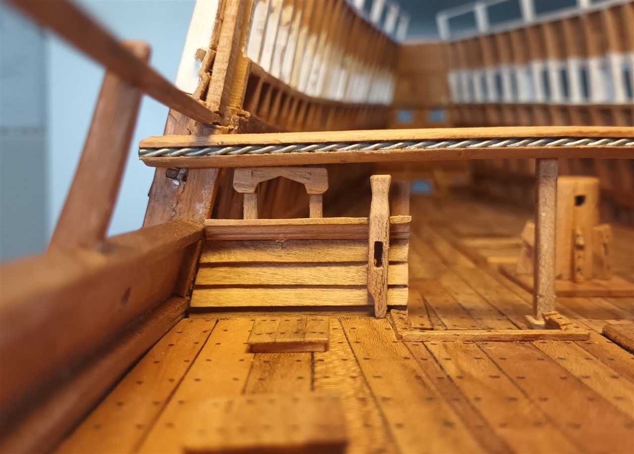
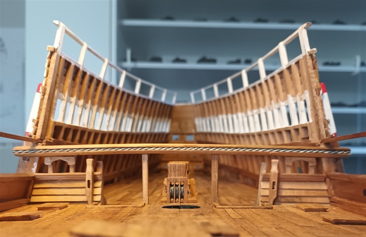
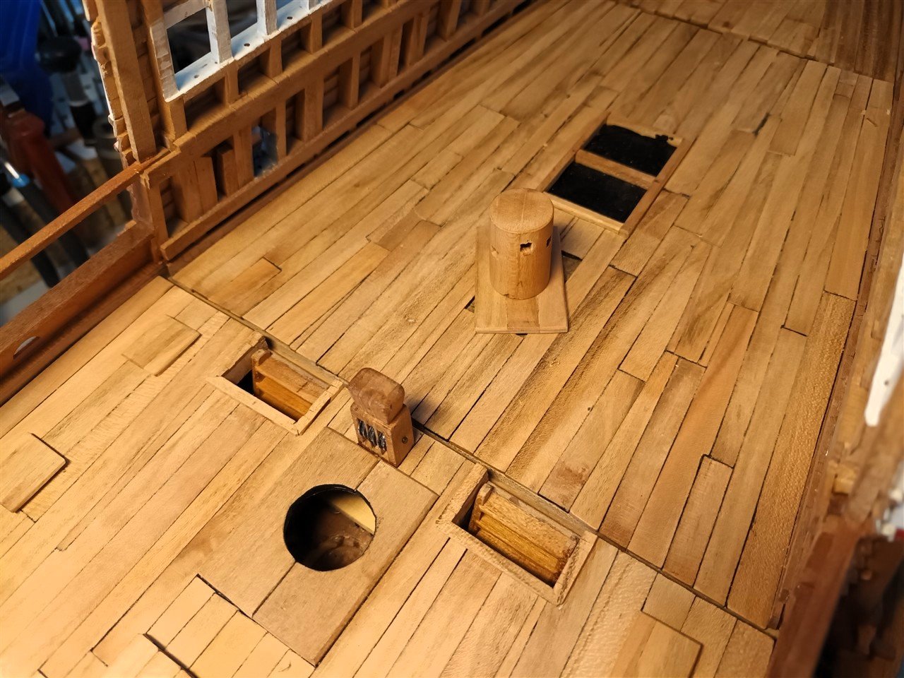
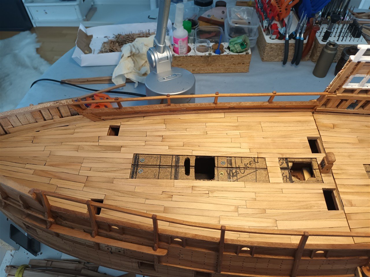
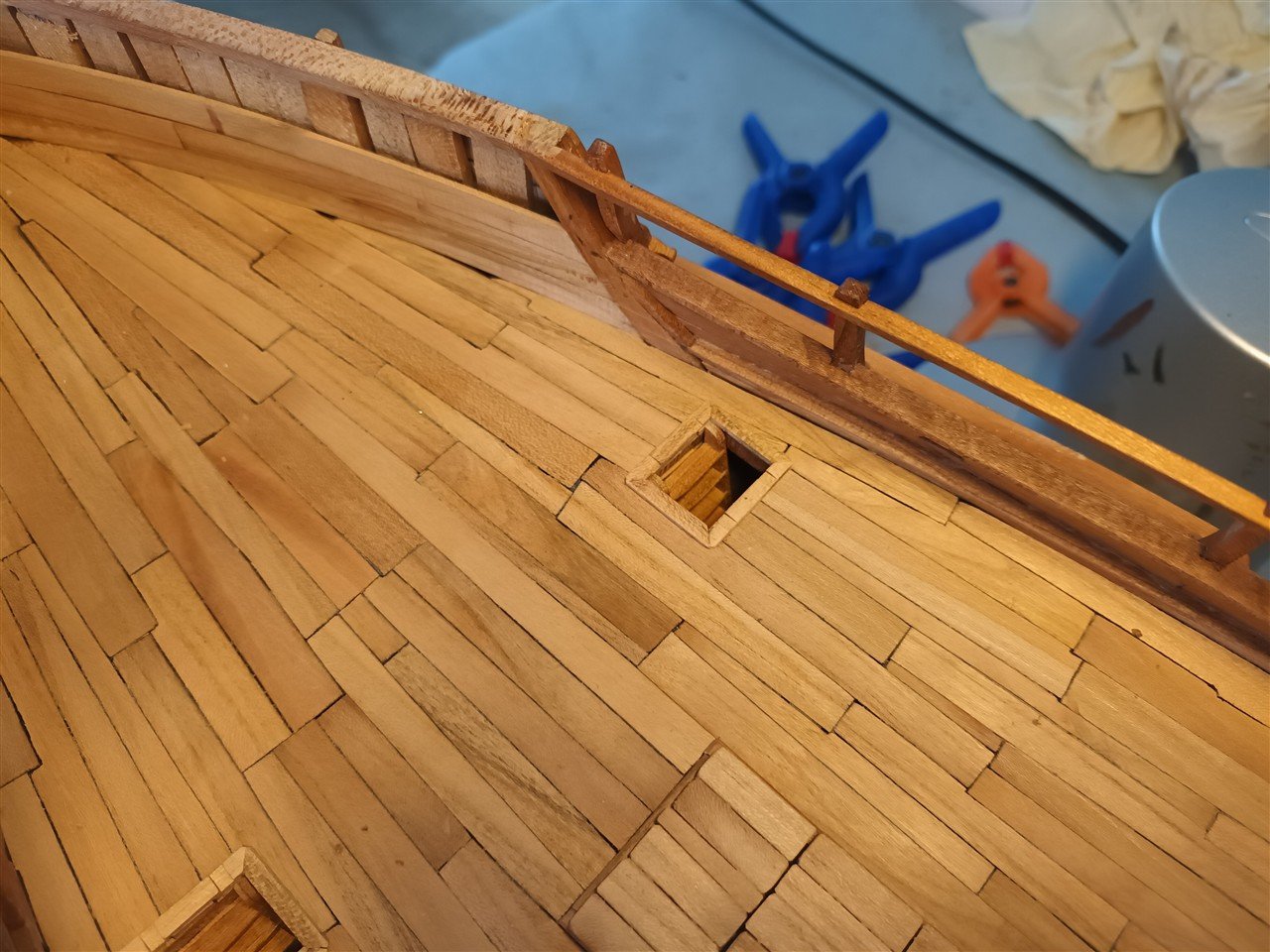
The arch under the fore castle
Contrary to previous assumptions, this did serve as access from the upper deck to the fore castle.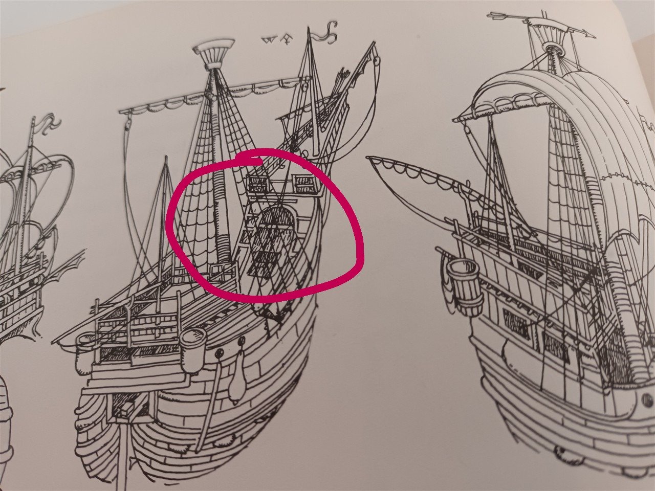
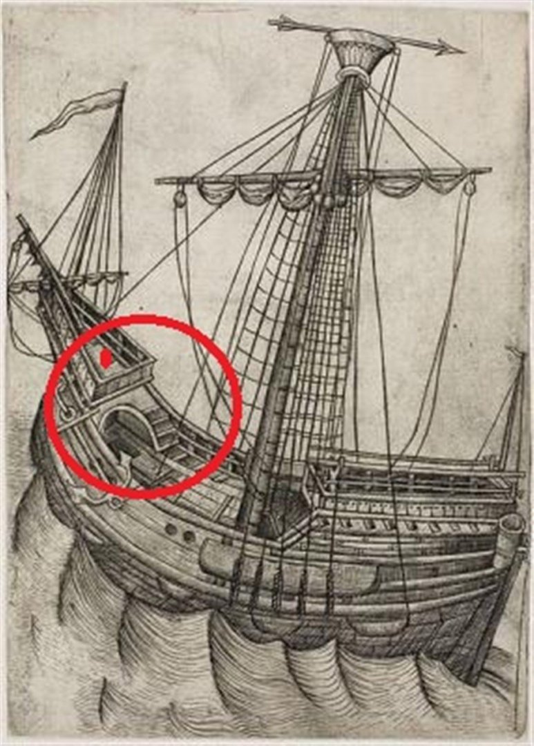
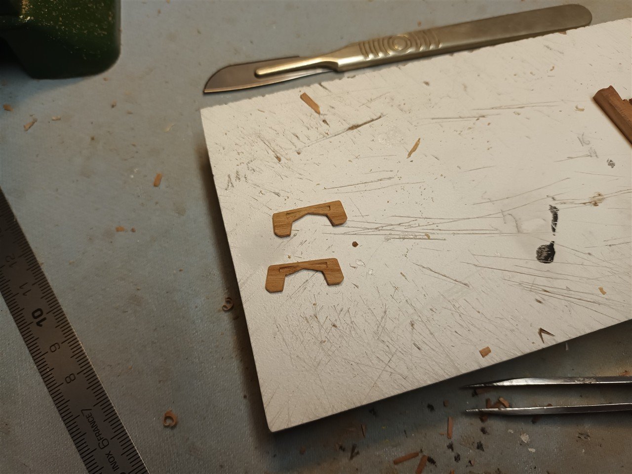
The construction was done step by step.
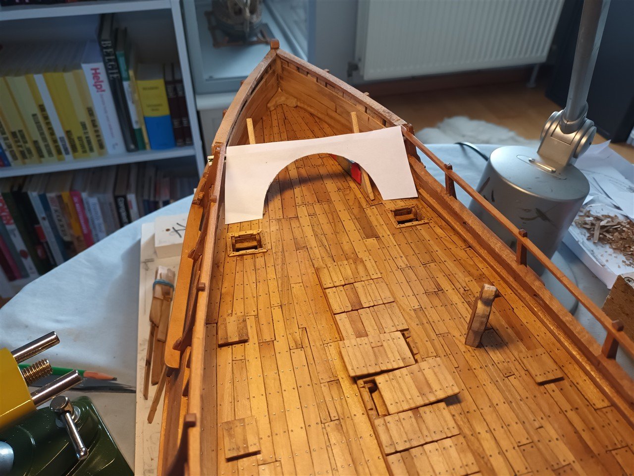
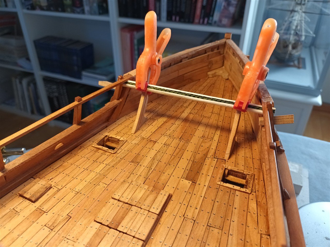
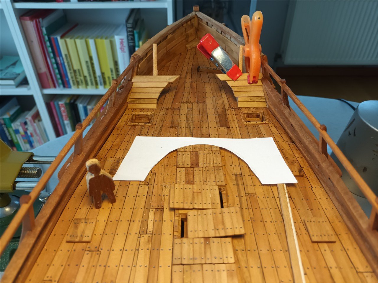
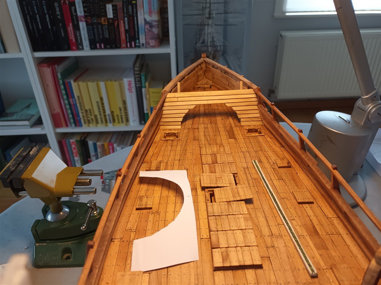
The carved arch."stair, ladder" not yet in place
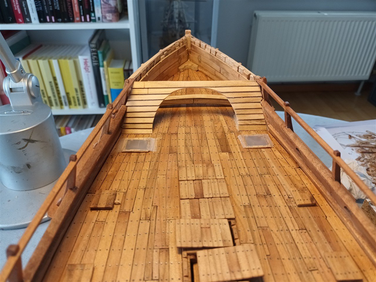
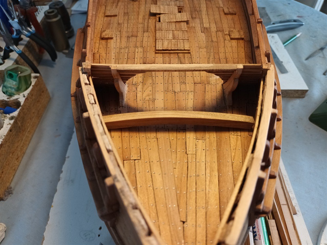
Some "oops" work was required. The fore castle deck was too high relative to the rear castle deck.
Otherwise, the walkway above the anti-boarding net wouldn't have been at the correct height.
dry fit (and a bit uneven at the moment, as I can see in the photo)
-
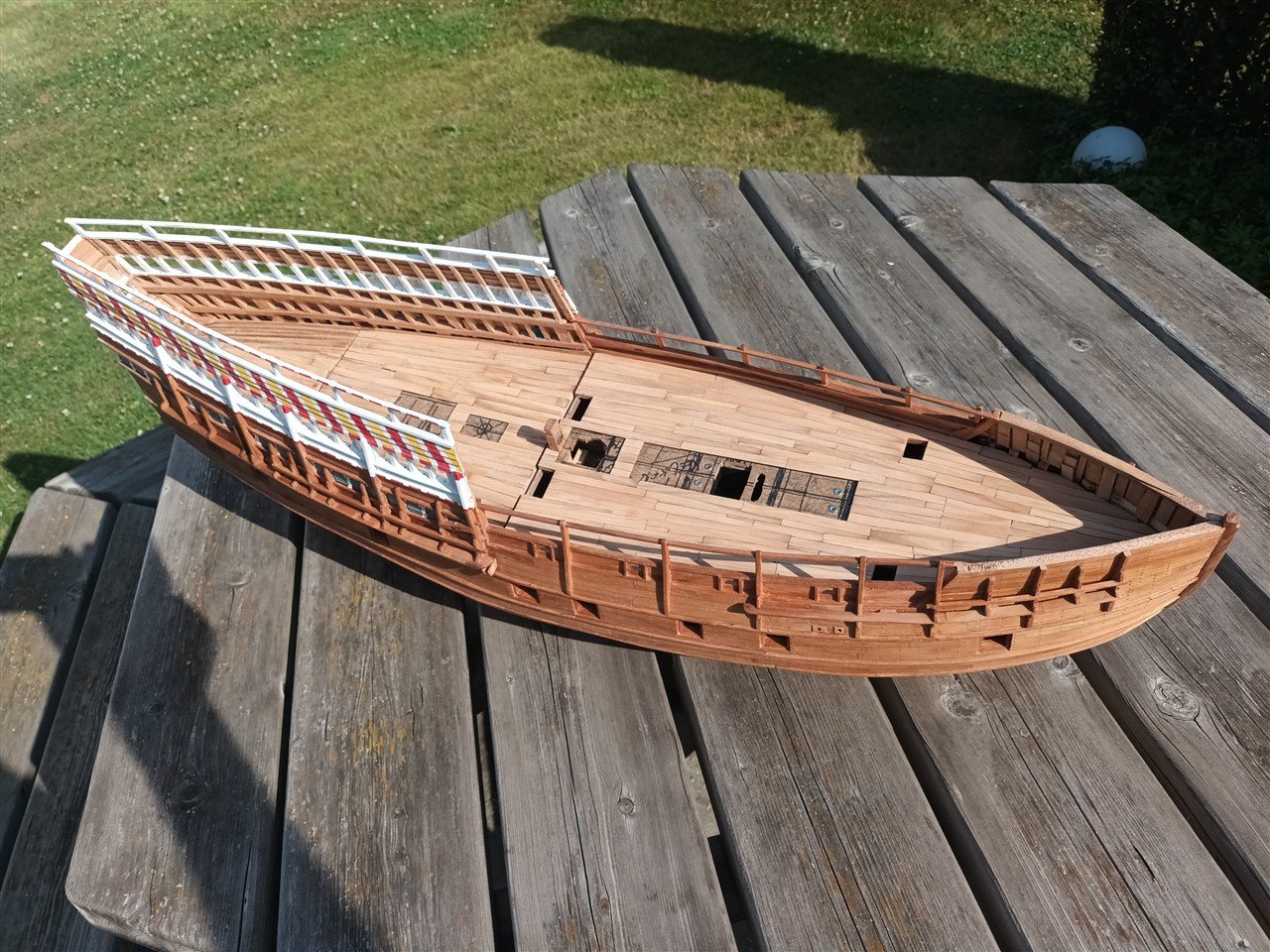
Nice model
And

-
-
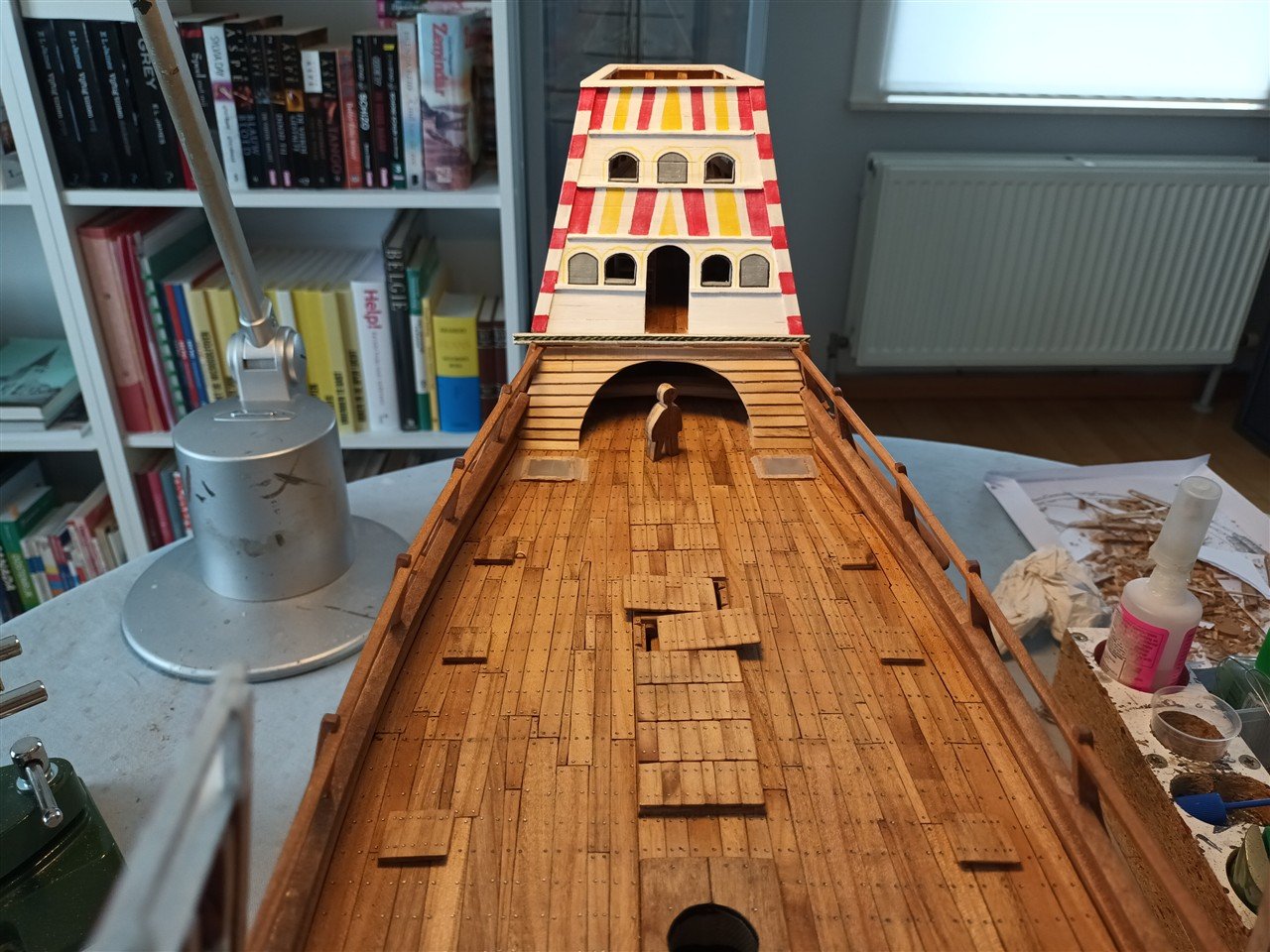
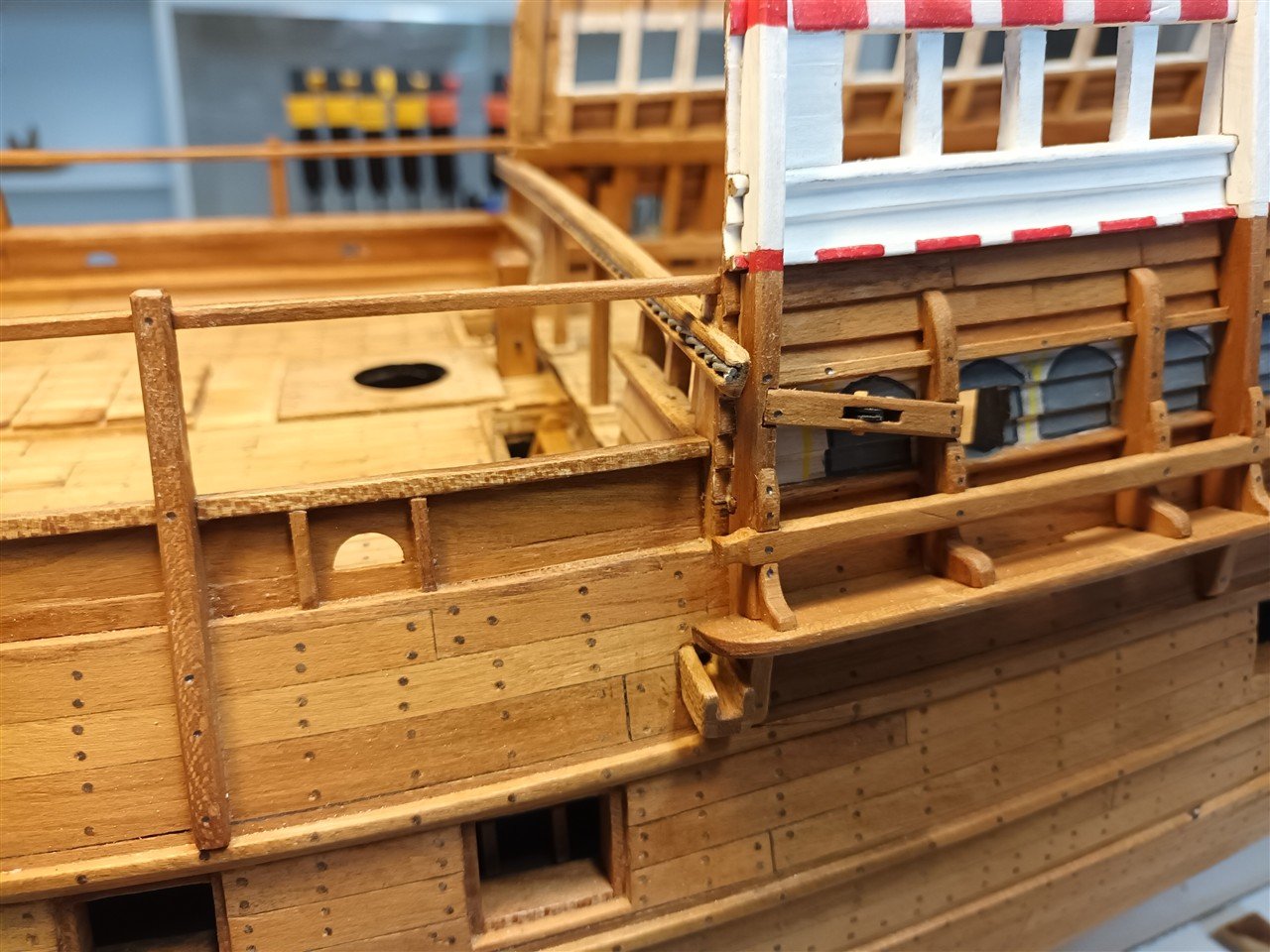
Reconstruction of the aft wall of the upper deck.
Drawing of what remains.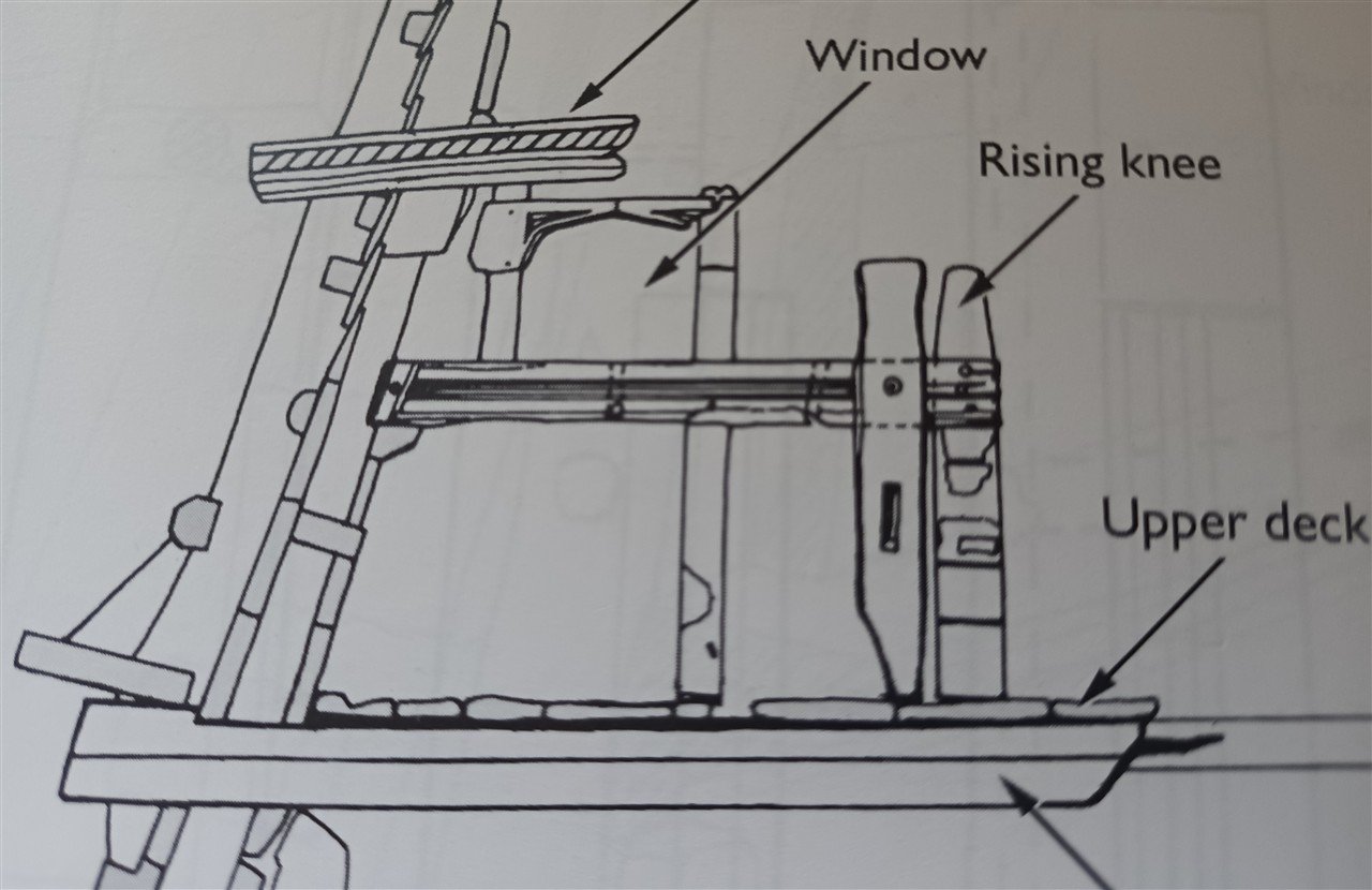
Result.
Swivel guns may have originally been placed here. That's why two holes were provided in the beam on each side. Whether these were still present after the renovation...?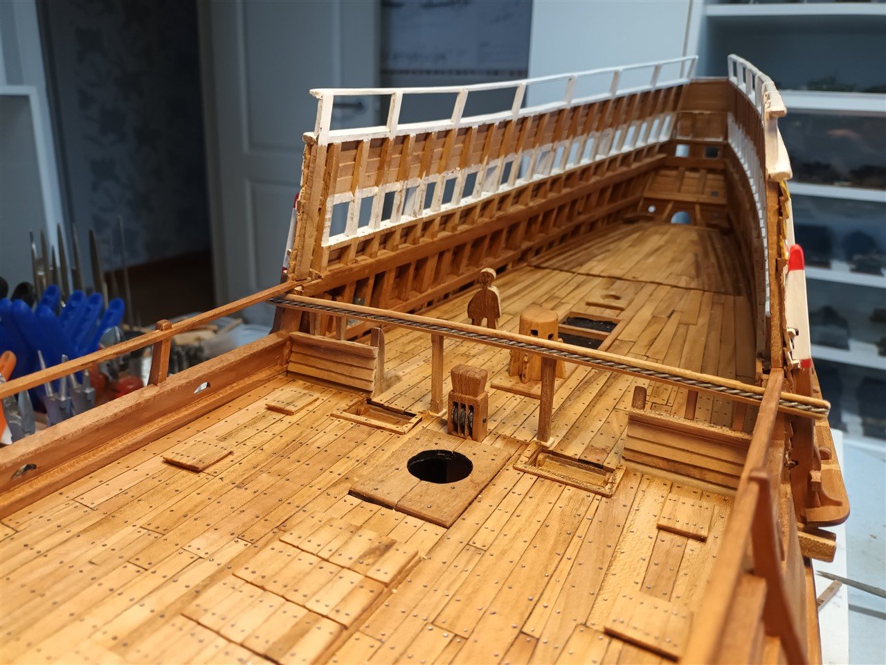
The supports in the middle are a guess.
The drainage channel of the deck above; once painted, you won't notice the wire anymore.
- Ronald-V, BLACK VIKING, Rock_From_Korea and 19 others
-
13
-
 1
1
-
 8
8
-
-
-
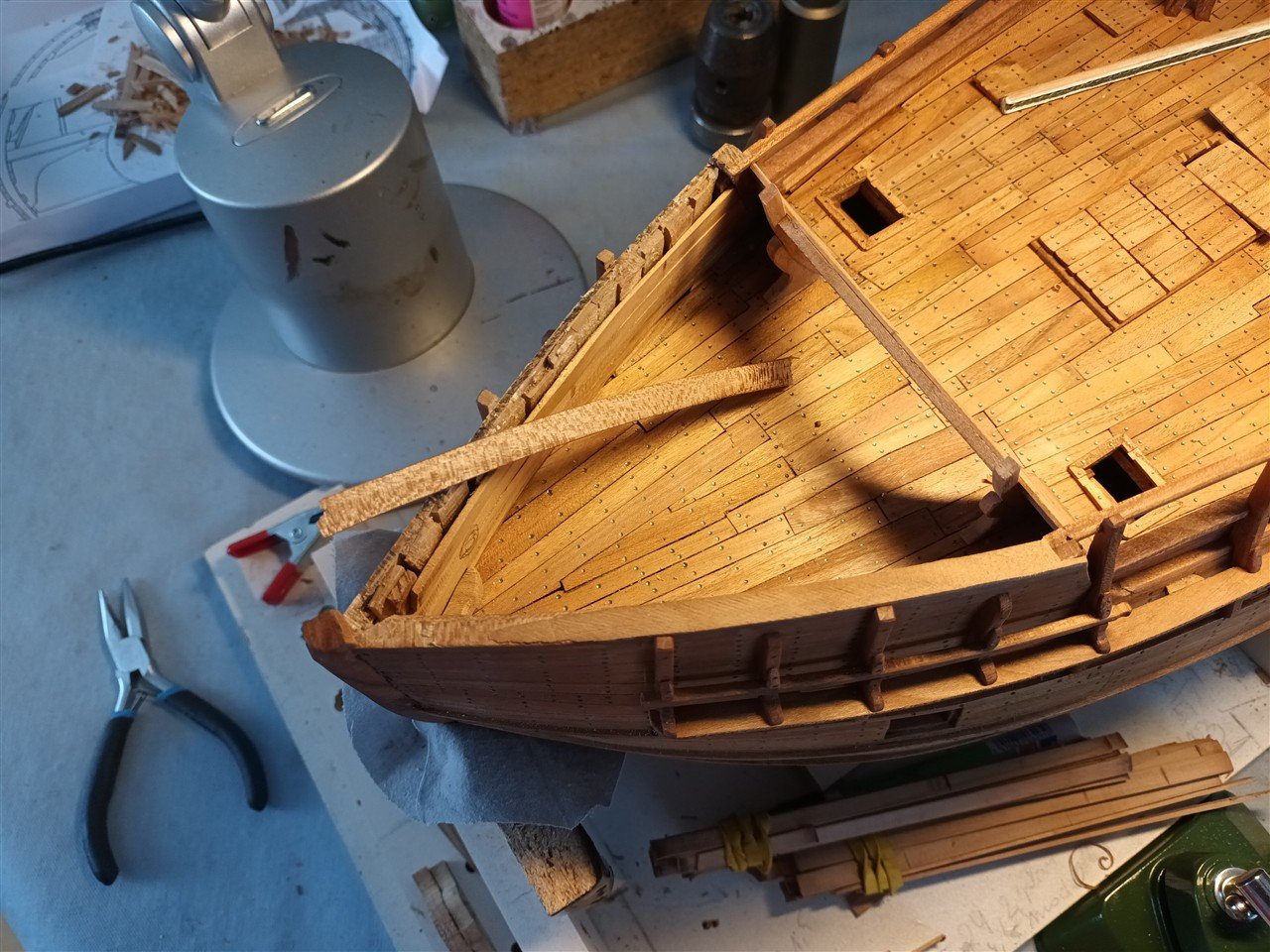
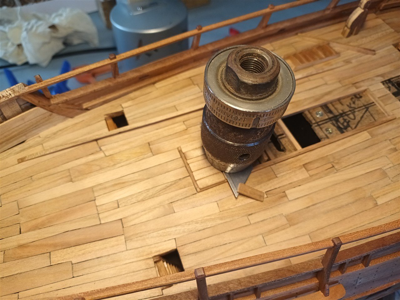
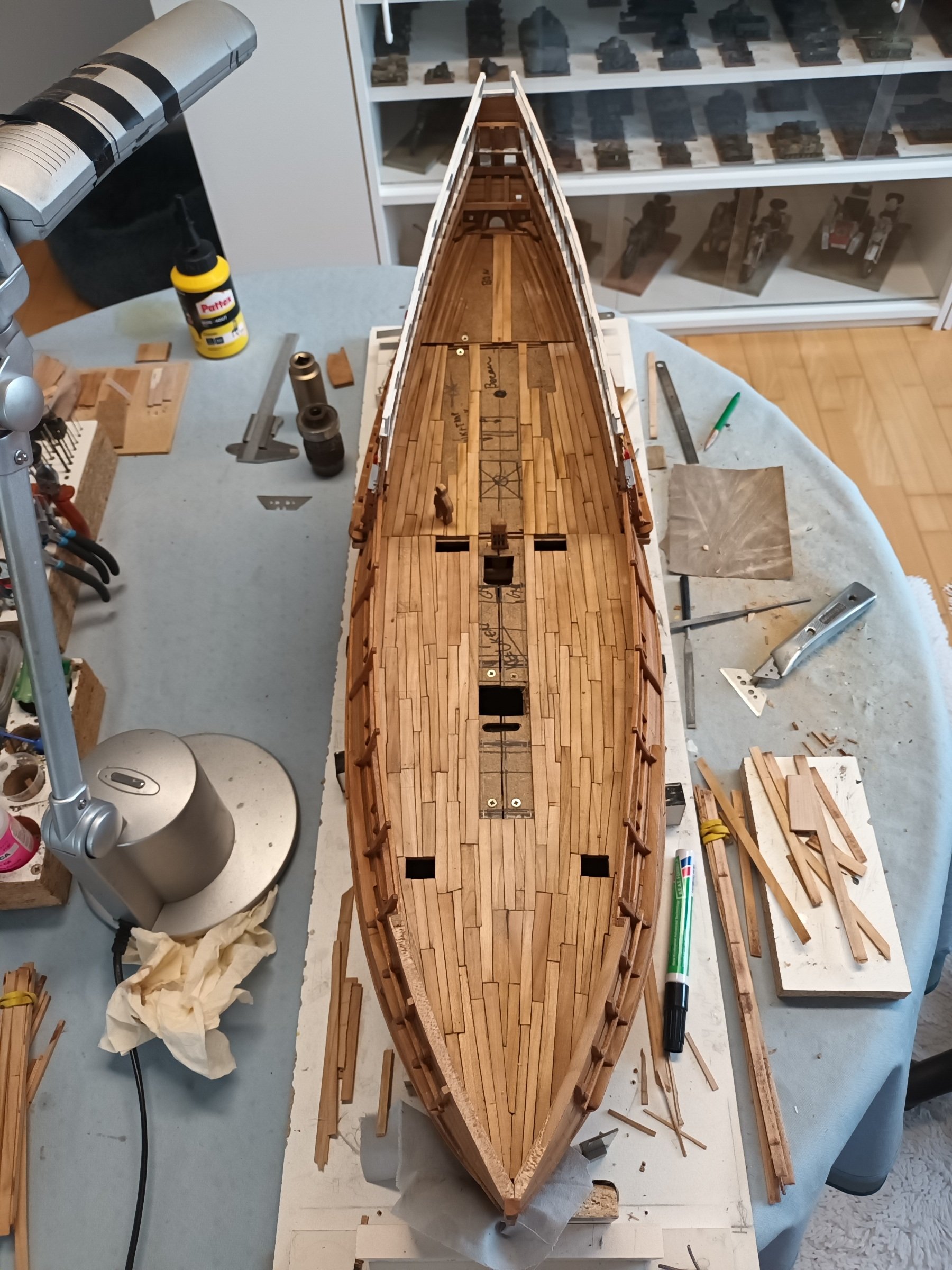
Construction of the various hatches on this deck.

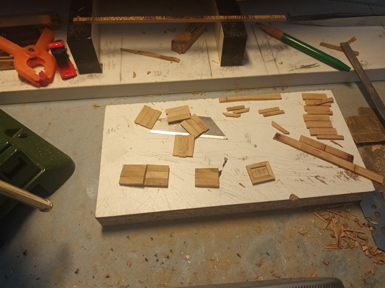
Eight small hatches, above each gun on the deck below. None are identical. It looks sloppy, but so be it...
Larger hatches are provided in the middle.
An anchor cable will later "disappear" under one.
A ladder will remain partially visible under another.
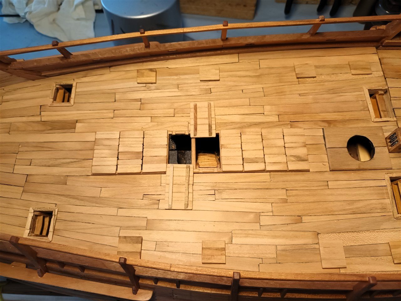
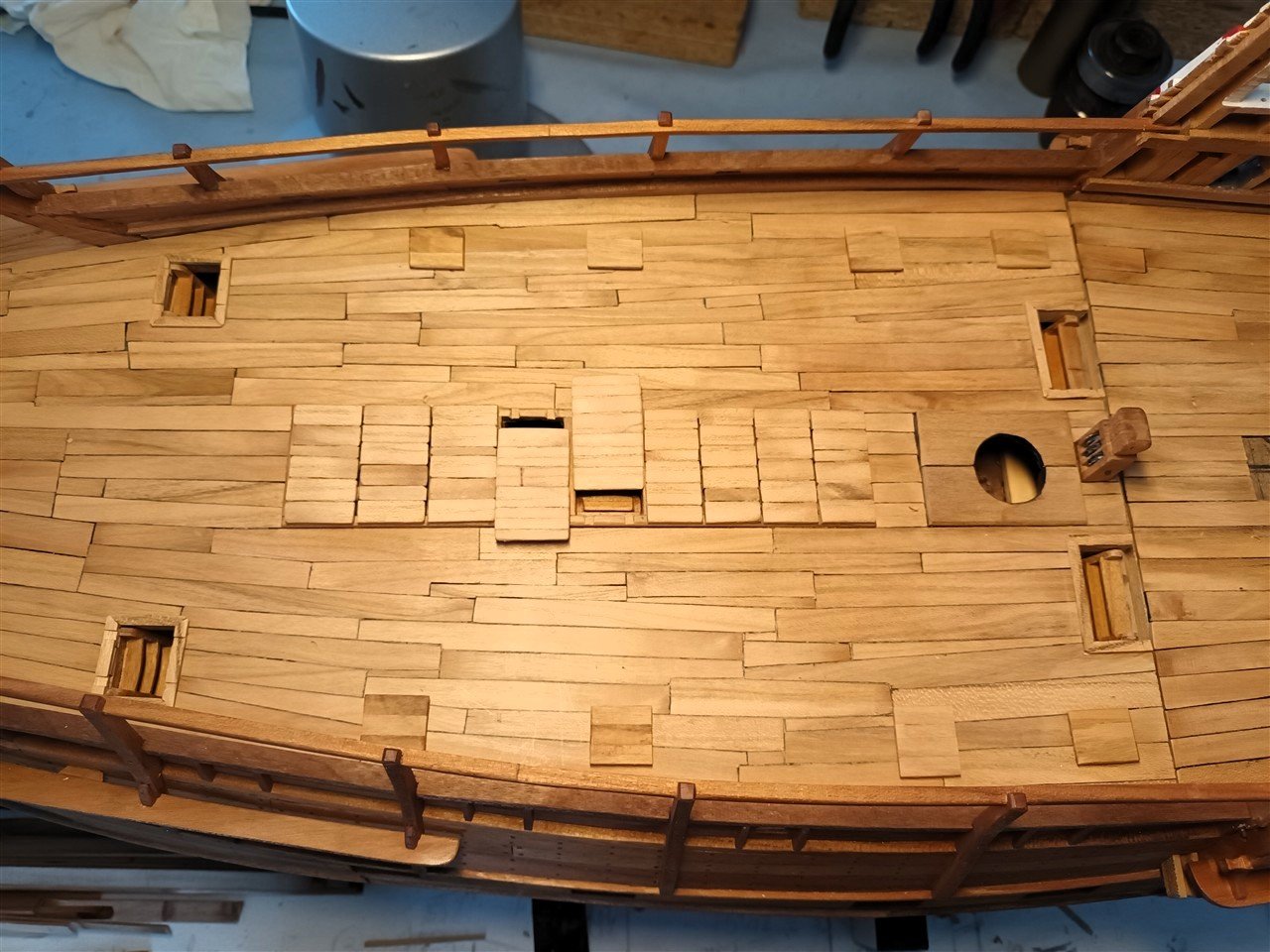
The mast is aligned, straight across the width and leaning slightly backwards along the length.

Capstan under construction
Thanks for following and likes
- fake johnbull, Siggi52, Thukydides and 18 others
-
20
-
1
-
-
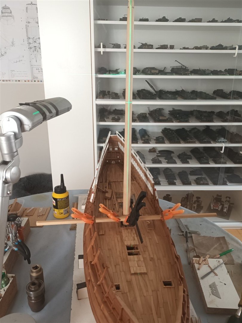
With the deck planking finished, the deck (outside in the garden) is sanded and dusted.
The planking at the back is virtually invisible later, so most attention has been paid to the parts that remain visible.
Ladders glued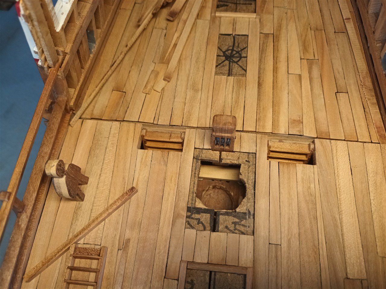
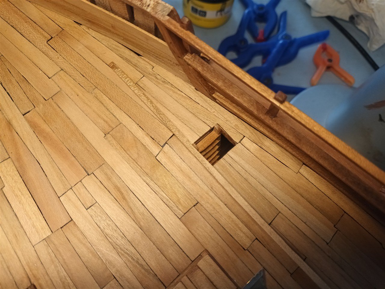
The openings around ladders and other openings are finished with planks with grooves milled into them. The cross beams of the hatches fit here.
(Most of the hatches in the middle will be closed)
Thanks for following
-
-
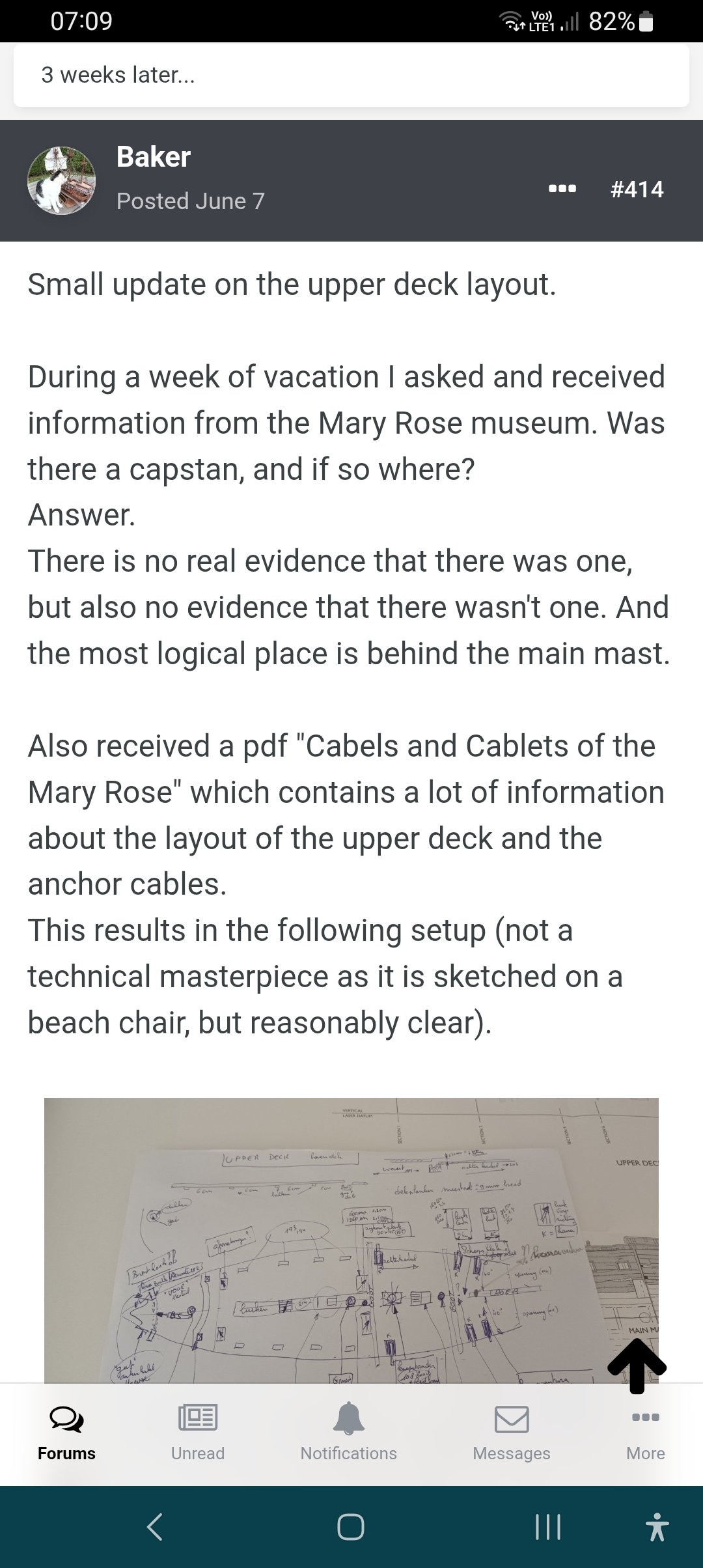
10 hours ago, tartane said:
Usually the capstan (spil) was set up in front of the mainmast and then in that case it could be set up on the axis of the ship. In this way he could hoist the lower beam of the mainmast (the line then went along the foot of the mainmast via a bitt placed diagonally behind the mast). The lower beam of the jib mast could also be lifted from the capstan (also via a bitt, but behind the foot of the jib mast). And the anchors could also be retrieved by the capstan. A capstan was the only very strong power source on a ship and was used for everything (hoisting cannons, sloops, cargo) and was on large ships indispensable. Small ships used a windlass.
Constant

As this pdf is copyrighted but available for around £47... through the Mary Rose trust, it is not shown or attached here
- Thukydides, 72Nova and GrandpaPhil
-
3
-
16 hours ago, tartane said:
The head seams of the planks should probably end on the underlying beams. Otherwise you can't nail it
Indeed, the underlying axis distance between large and small beams is approximately 1cm on this scale
Therefore, the distances between the seams, measured from the dale, are always with one centimetre in between.
This is almost the only constant in this planking
And the Anchor cable wil not toutch the main mast
btw,
There are anchors on starboard and port side.
if I place the capstan off center then i can only operate the anchors on one side
-
-
-
-
Kevels made from "wasknijpers" (Dutch)
well found and very realistic

- robert952, Paul Le Wol and AON
-
3
-
-
Beautiful model, and i learned a lot 👍


Amazing Resource! Hello.
in New member Introductions
Posted