FriedClams
-
Posts
1,368 -
Joined
-
Last visited
Content Type
Profiles
Forums
Gallery
Events
Everything posted by FriedClams
-
 I bet that was fun and a tad nerve-racking. Beautiful work, Keith and a major milestone indeed, especially on such a long hull. Congratulations! Gary
 -
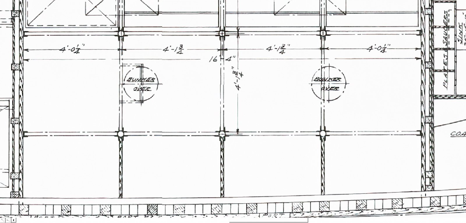
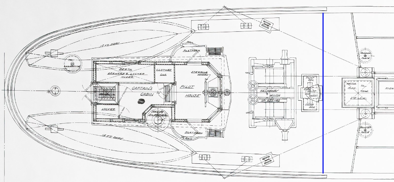
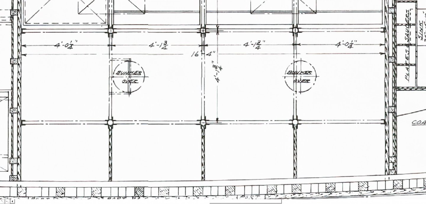
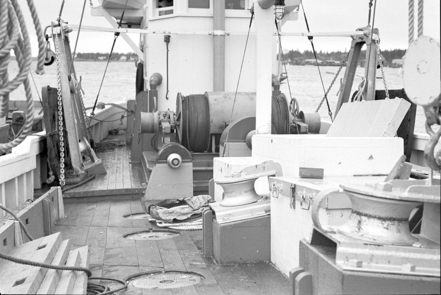
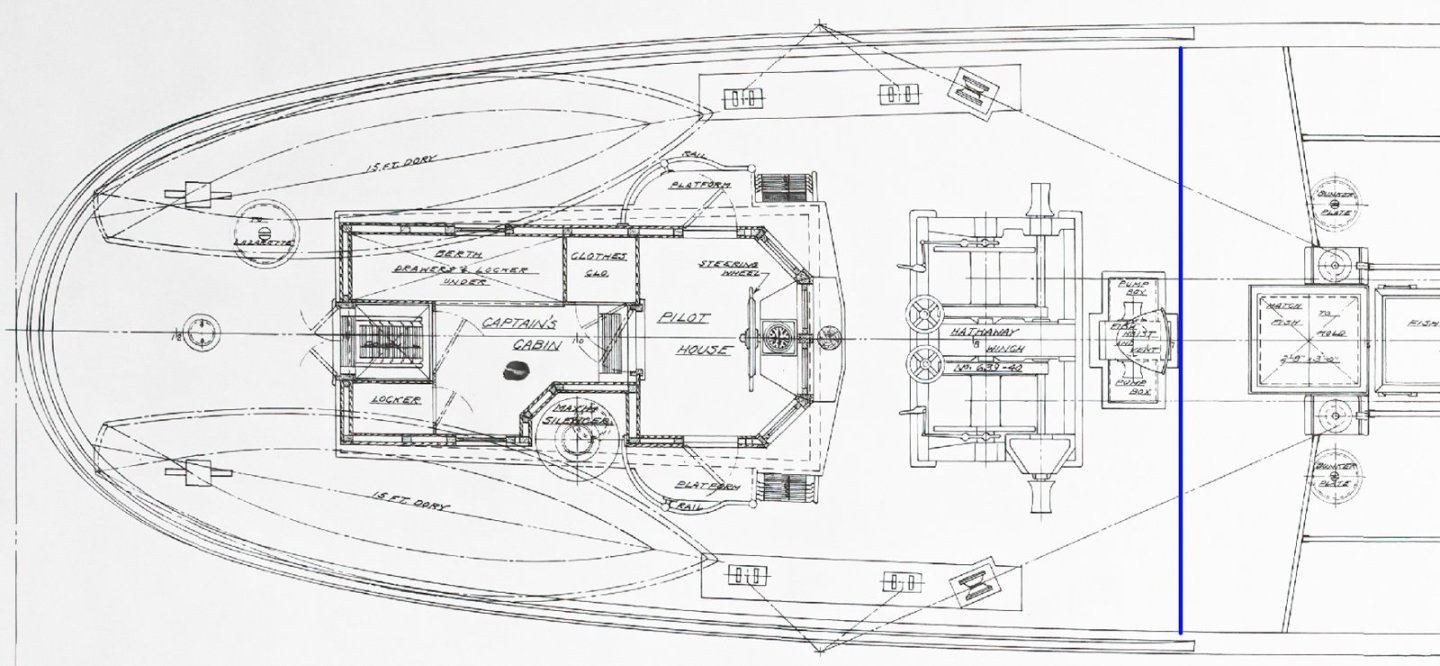
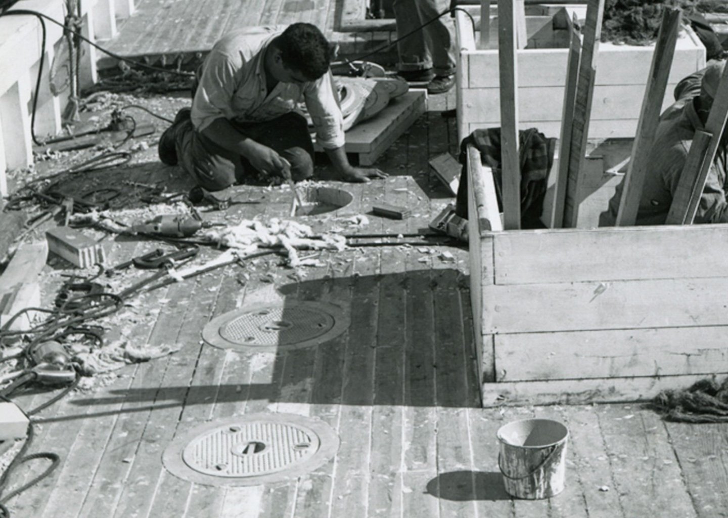
Druxey, Keith A and Glen - thank you kindly for the nice comments. And as always, thanks to all for the "thumbs up". Hello Keith and thanks for your post. Yes, they did use a single plate to service two bunkers, and they did this by positioning it over the partition walls separating two bunkers. See the deck detail below. Notice the plate to the left is positioned entirely over one bunker, but a jog in the partition wall was constructed to share half of the opening. Or at least that is the way it appears to me. Obviously, the plate position is dictated by the deck beams and there just happens to be one over that partition. But I don't believe there is enough room at the top of the partition to sort of snorkel over it though. What baffles me is why not simply add more plates to where they are needed like the boat below, and I'd be willing to bet the photographer is standing with one right in front of his feet. Also, the plate spacing in the photo of the shipwright in the post above suggests to me that there will be a fourth one behind him in the area of the skid. Here's what I'm wondering. The Pelican was designed in 1943 during a time of severe metal shortages due to the war effort. Ration stamps for food and gasoline were a part of everyday life. No automobiles, commercial vehicles or auto part were manufactured from February 1942 to October 1945 and all focus had shifted to wartime production of ships, tanks, planes, etc. Large fishing vessels were conscripted for military activities, but smaller F/V prospered due to wartime protein demands. So, it seems you couldn't buy a new dump truck, but you could have a new F/V built. A wooden dragger does have quite a bit of steel and iron on it, most of which is necessary like a winch, diesel engine, gallows frames and steel cable. But are eight bunker plates necessary if you can get by with four? Or was it because every foundry no matter how small had shifted to military component production and bunker plates were simply hard to find? I don't know - just typing out loud. Thanks again. Gary
-
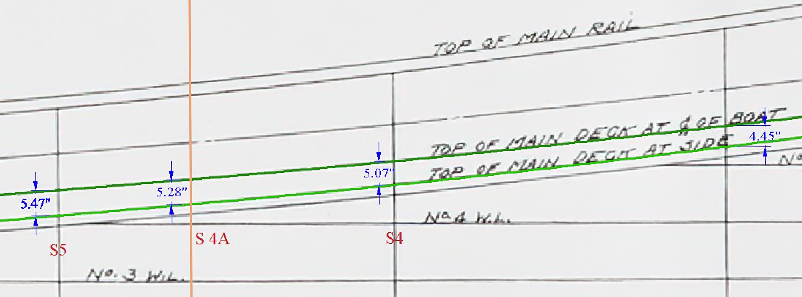
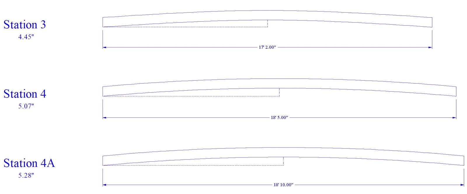
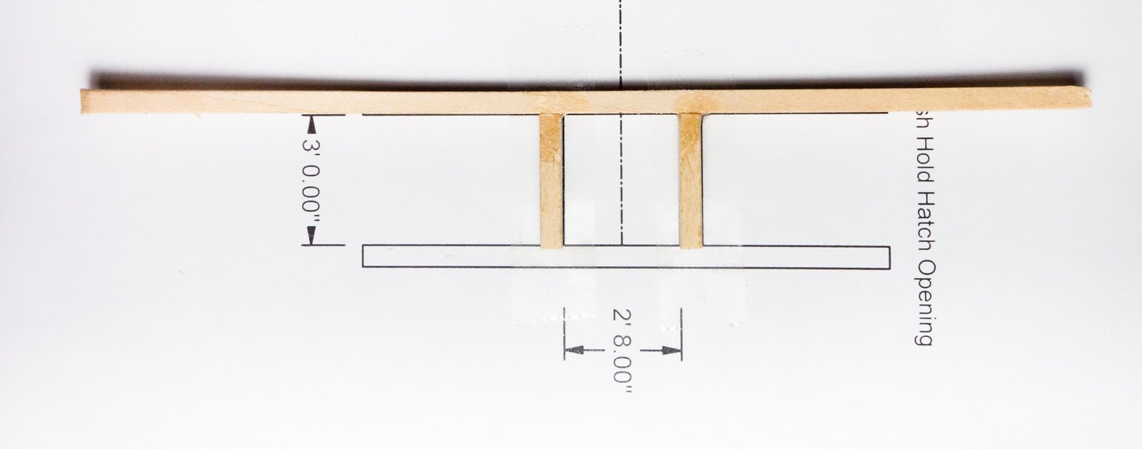
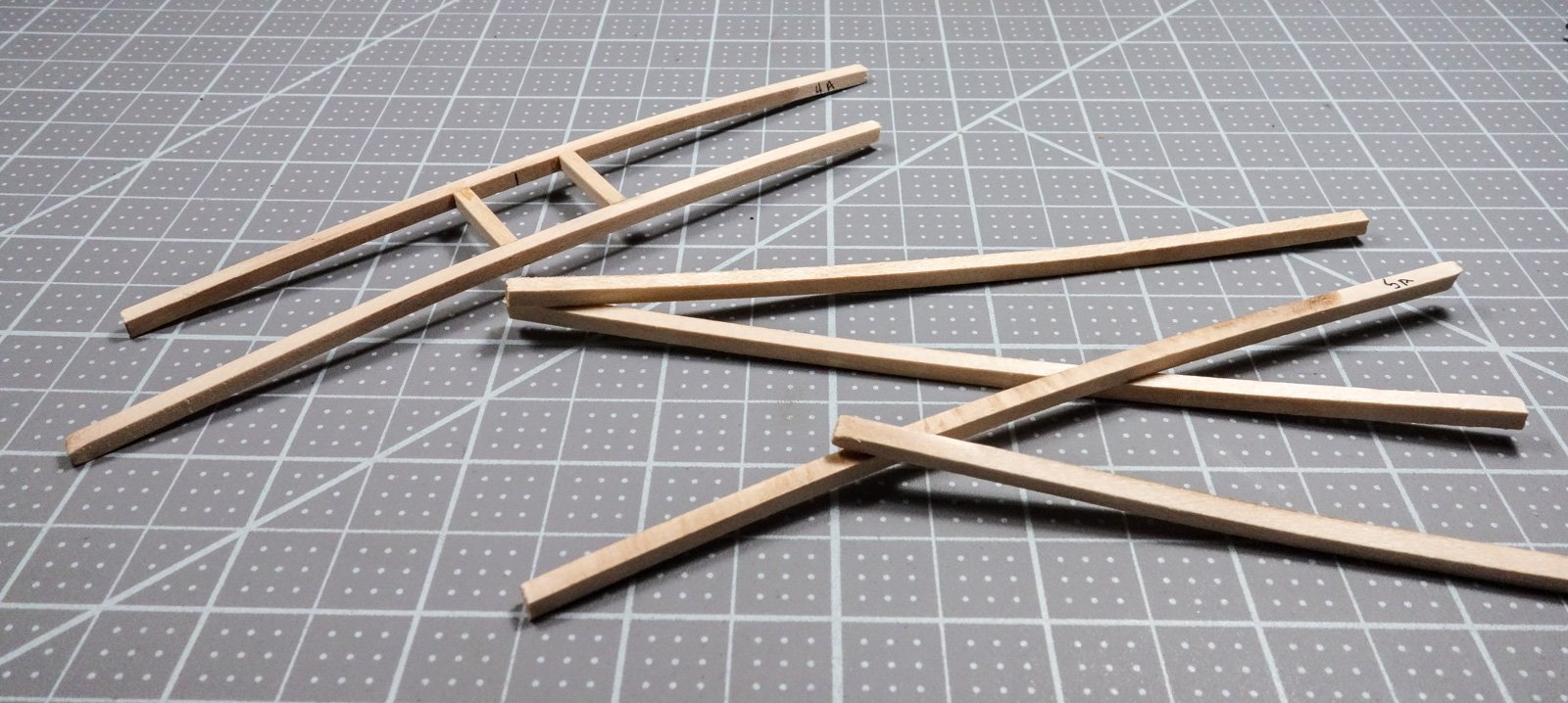
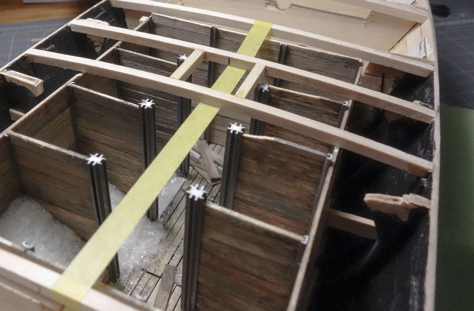
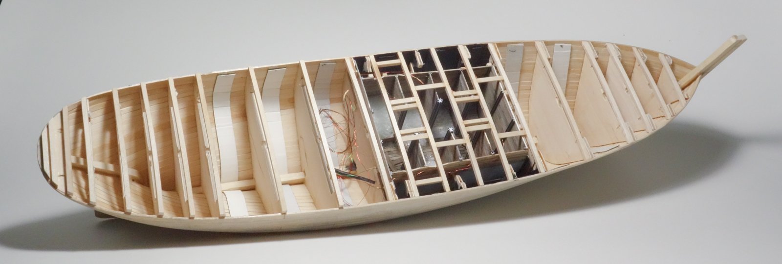
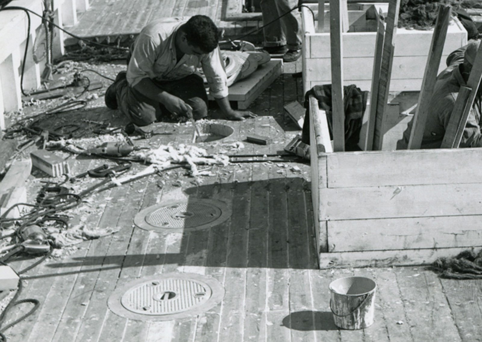
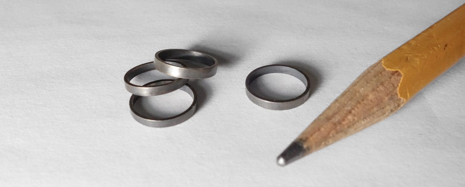
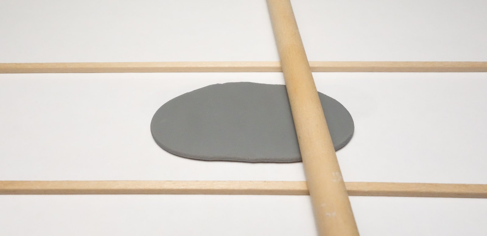
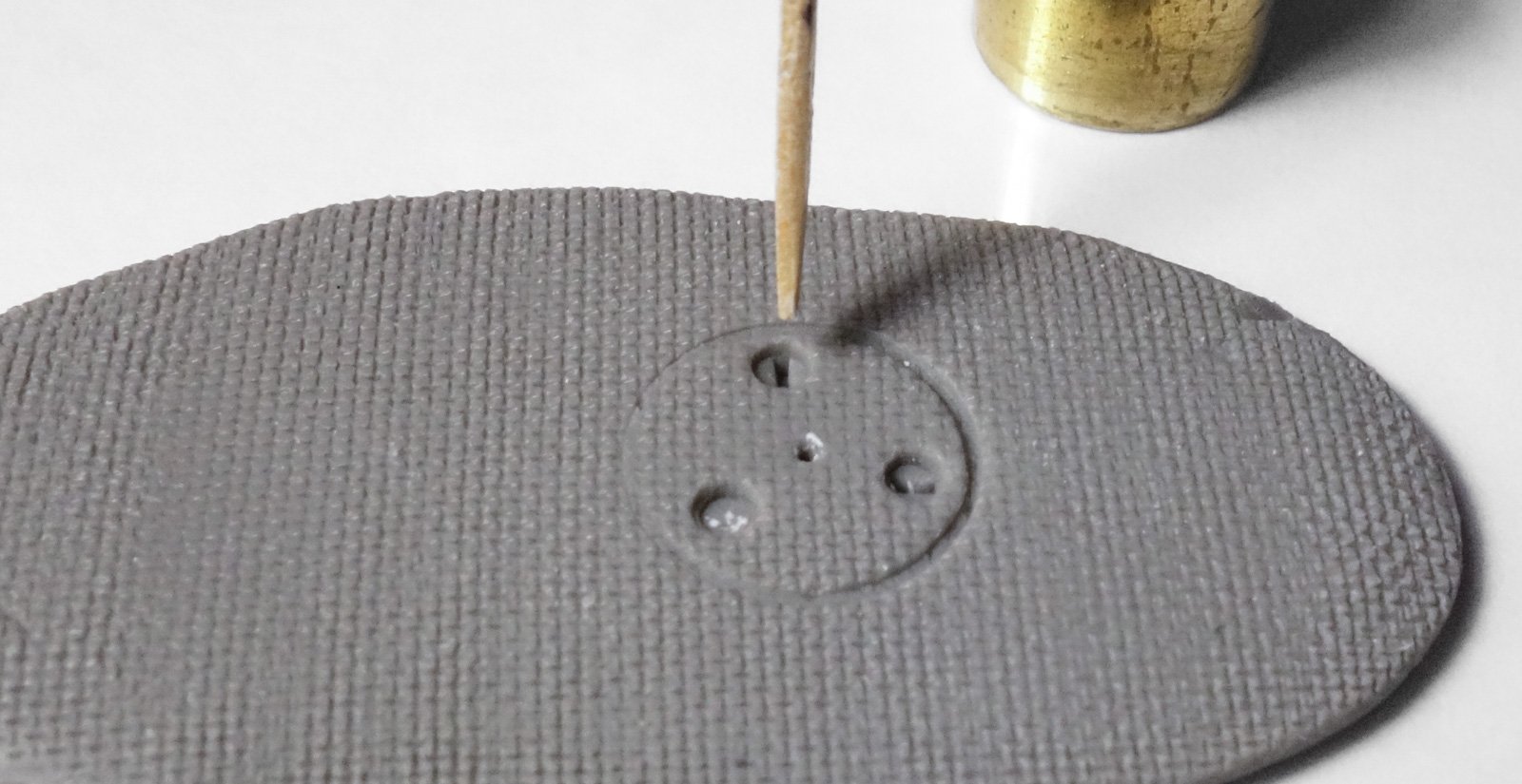
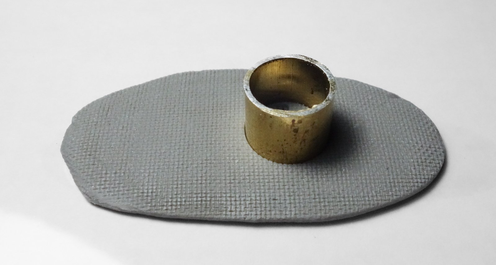
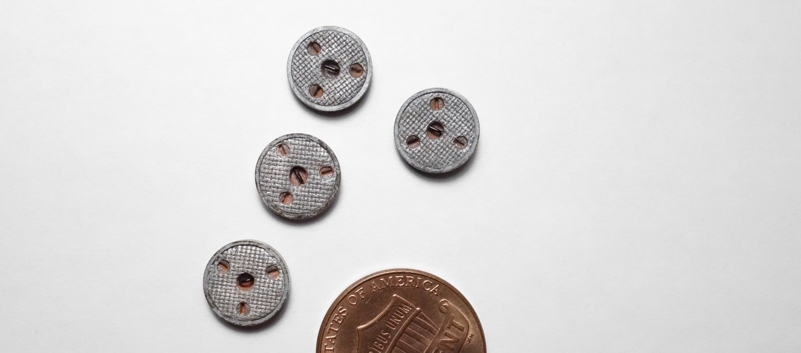
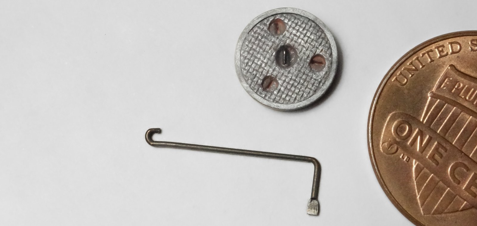
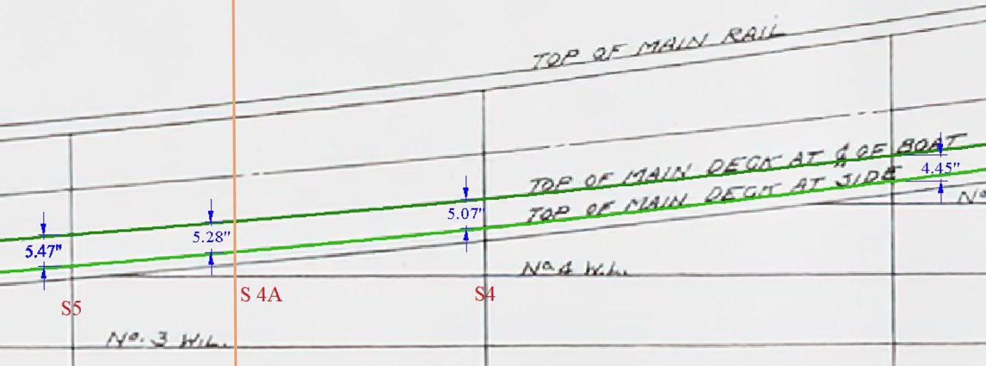
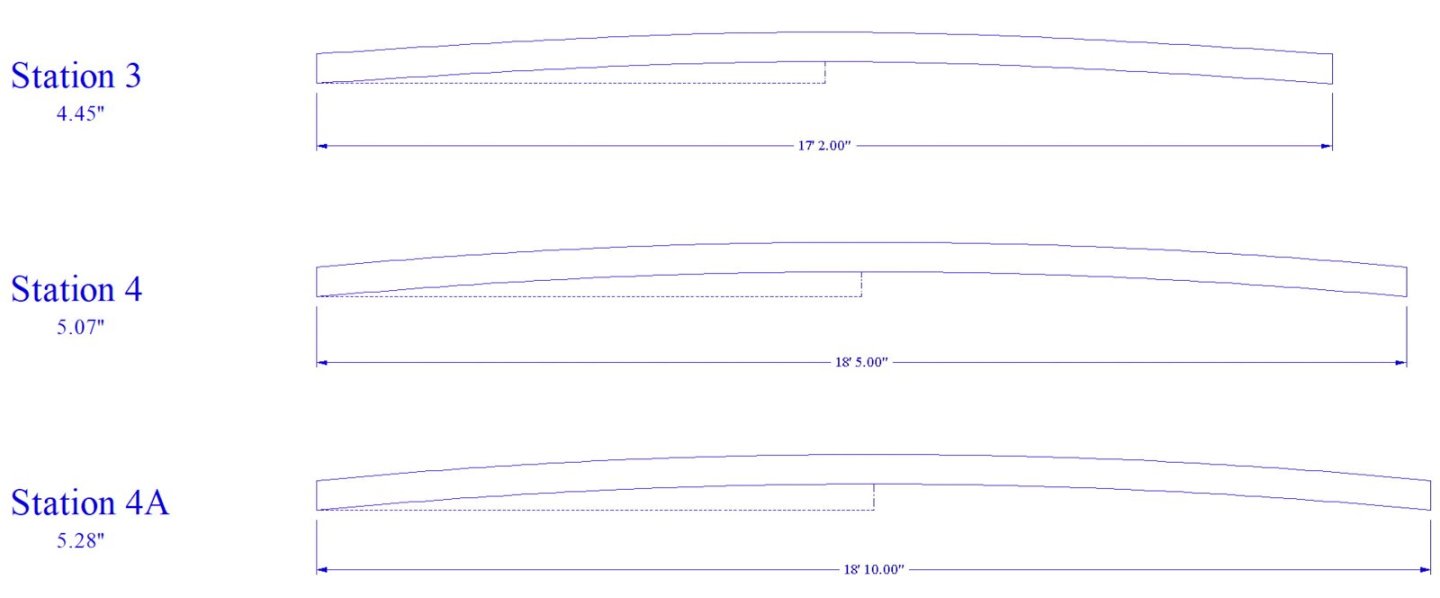
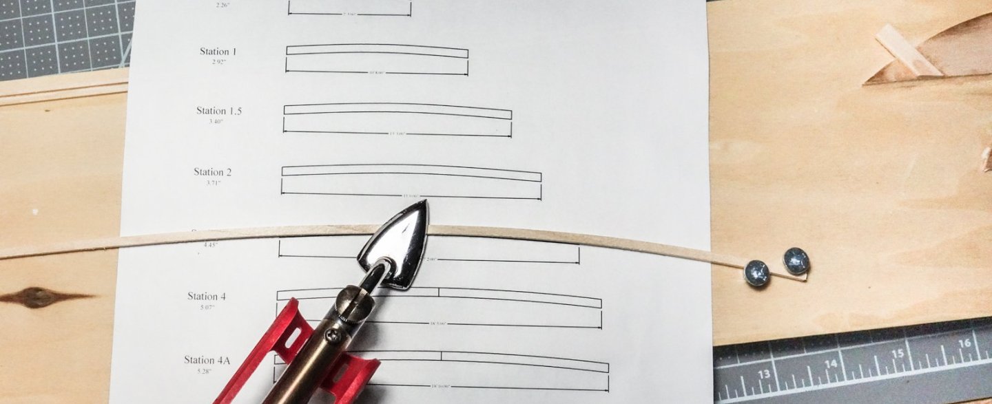
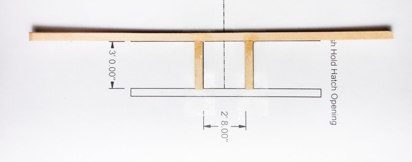
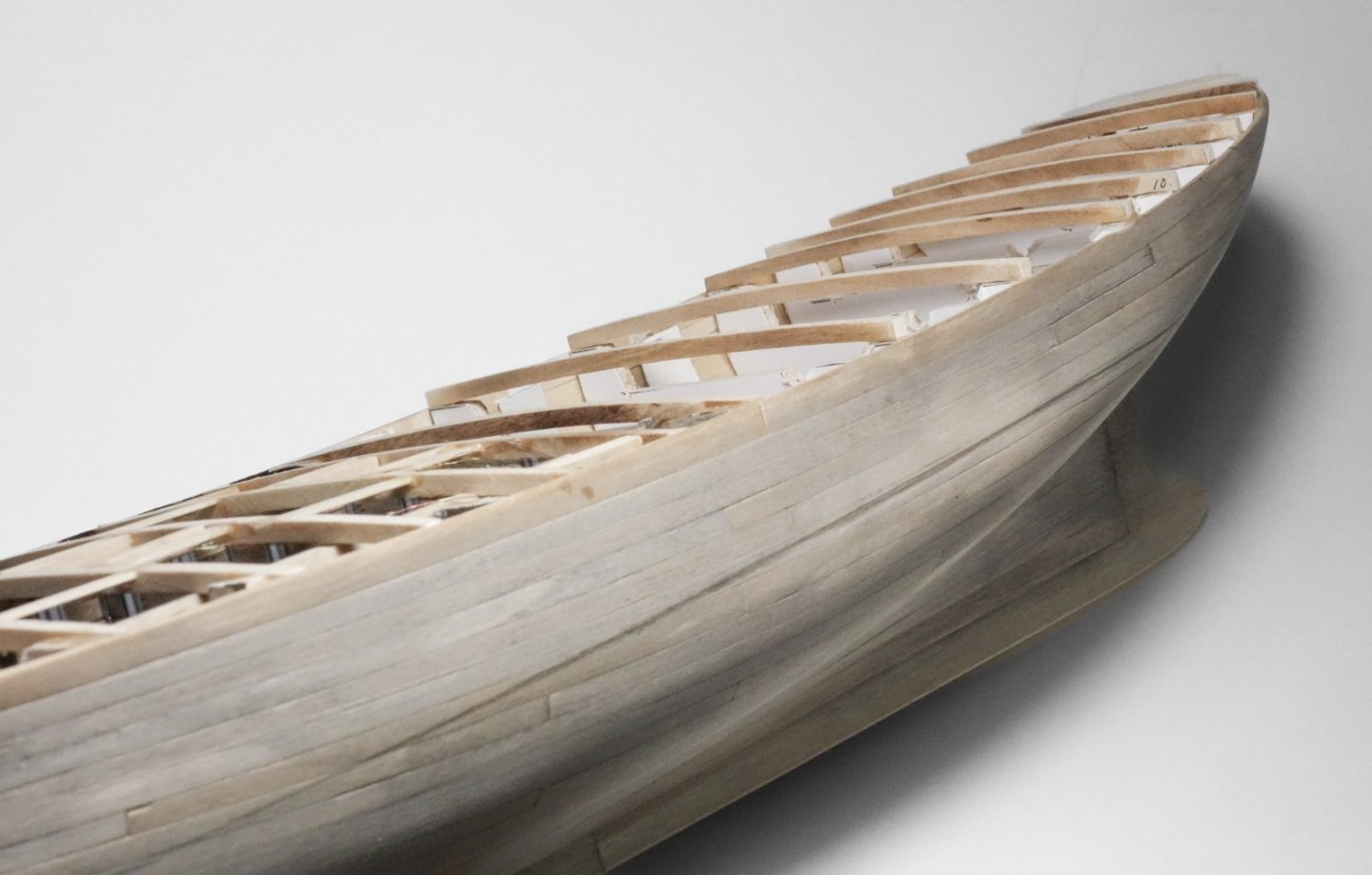
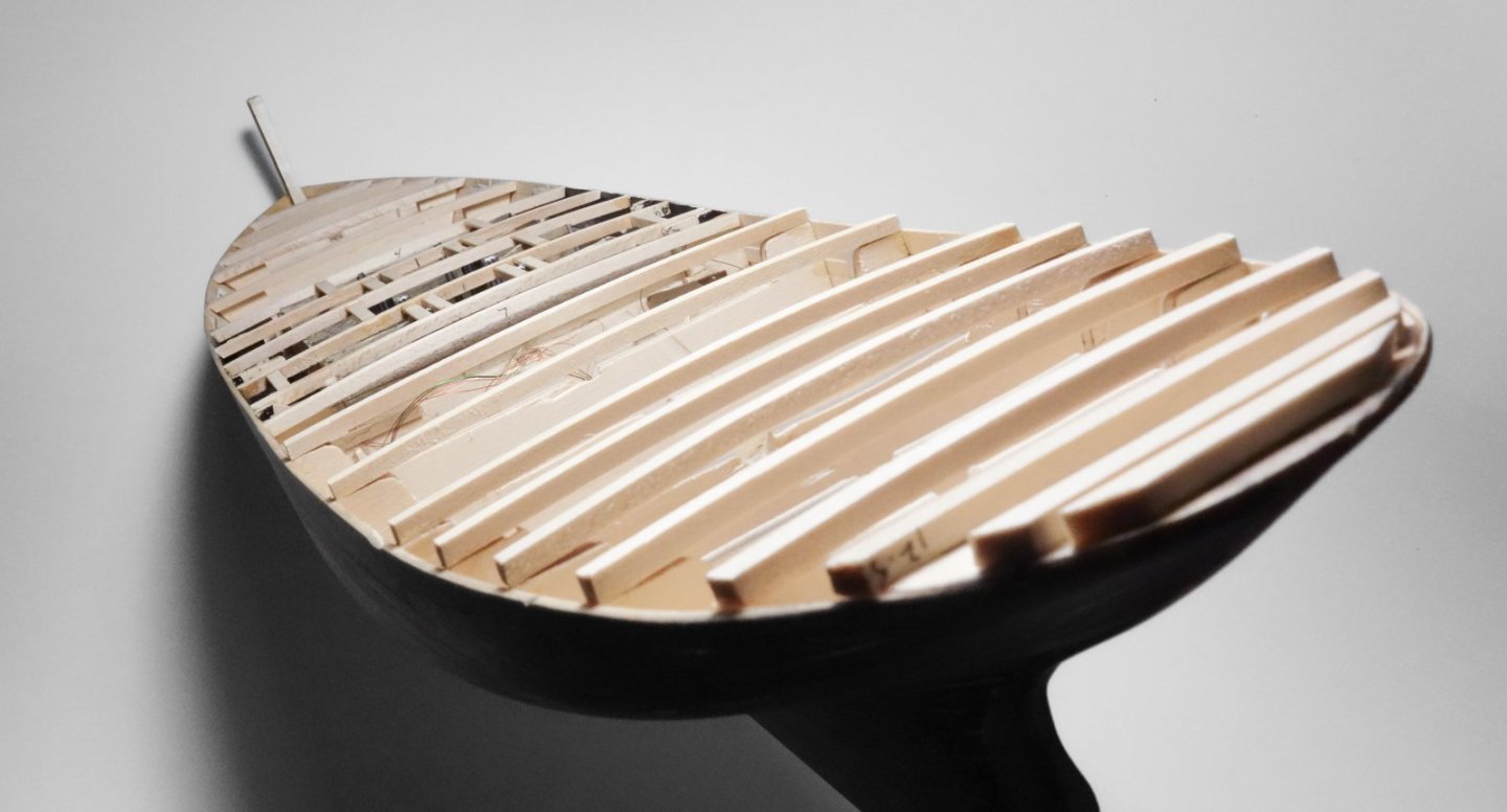
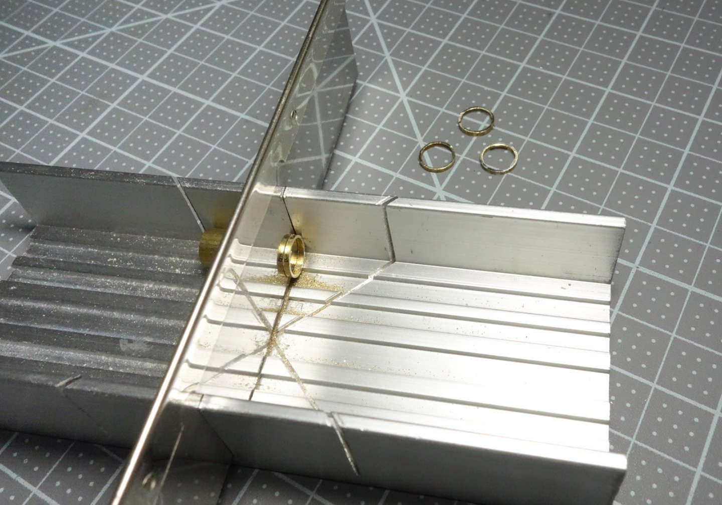
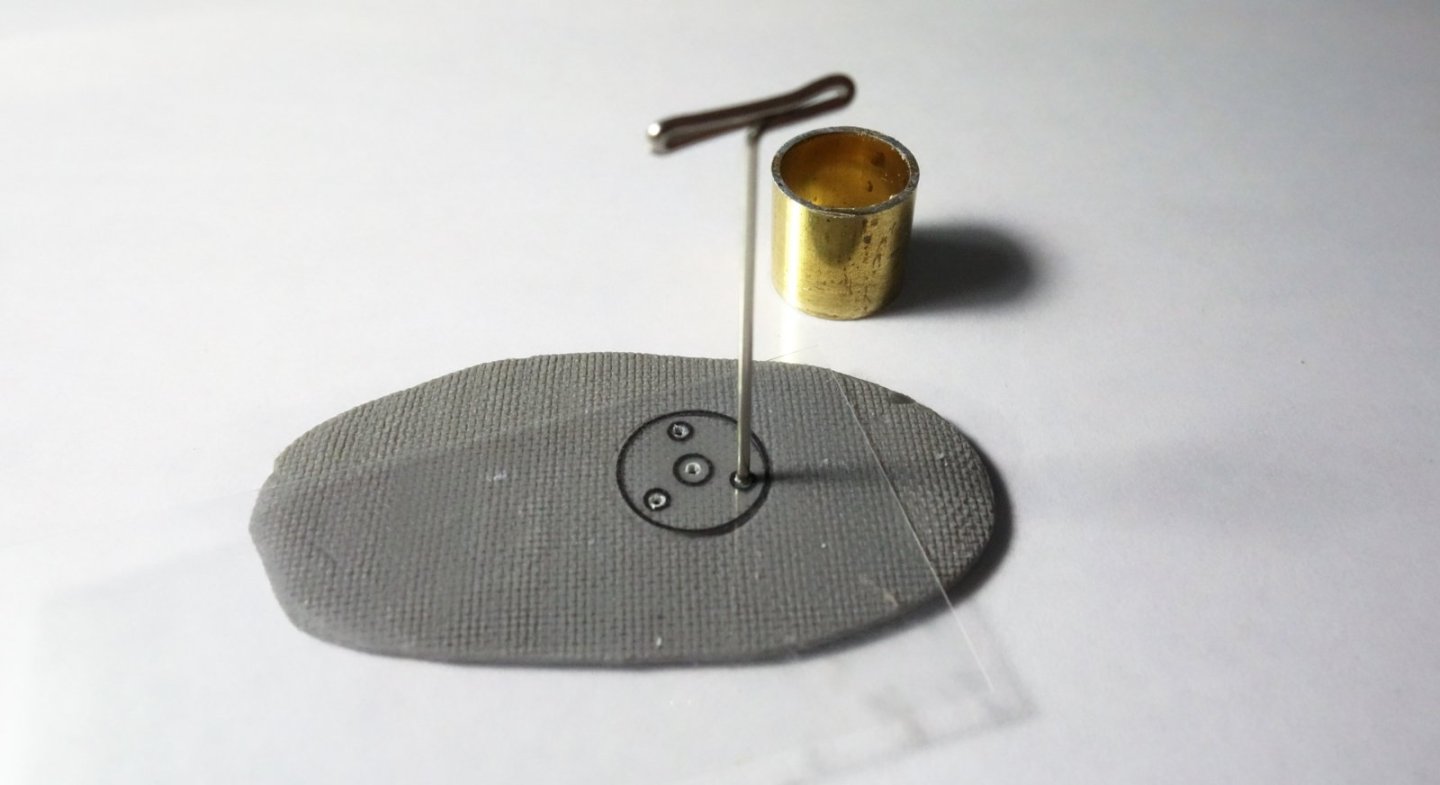
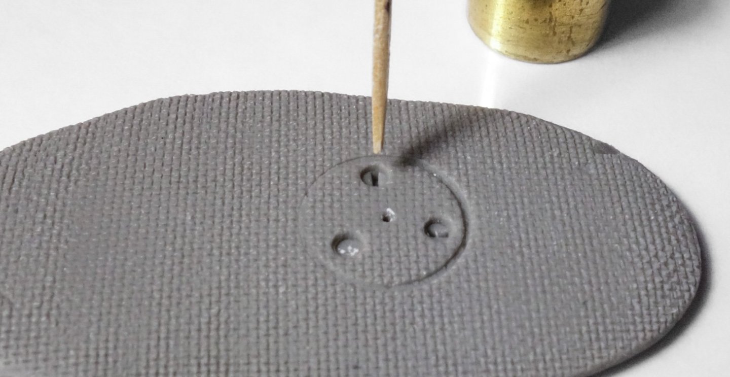
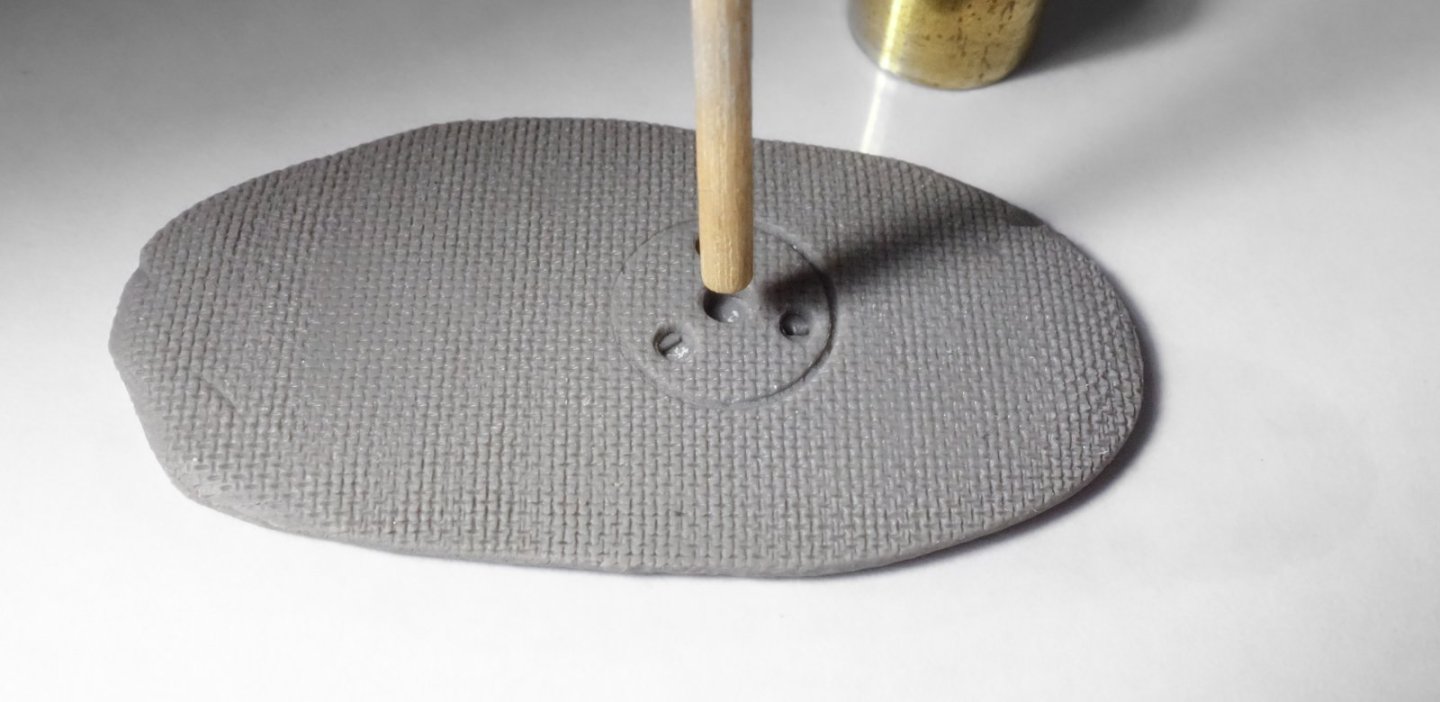
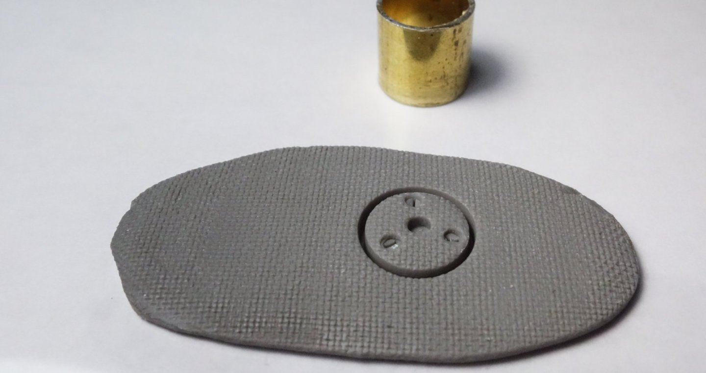
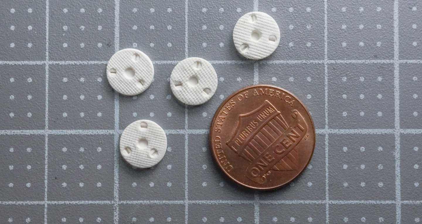
Greetings Fellow Modelers Marc, Valeriy and Jerome - thank you for your kind words and thanks to all for the "thumbs up" and stopping to take a look! Deck Beams I've been working on the deck beams and they are now in place. Even though I'll be using rather stout deck planking, I will most likely be adding intermediate beams where the spacing between them is too wide. I determined the crown of the beams by measuring the distance between the “top of main deck at side” and “top of main deck at center.” This measurement and the distance of the span across the hull, defines the beam at any given point along the length of the hull. And it provides a template in which to shape and cut the beam. The crown of the deck is not consistent from stem to stern meaning that in some areas the arc is flatter/shallower than other areas. I plotted the arc of each beam individually, but to be honest, they were so close to each other that this exercise felt unnecessary and at times pointless. The beams are scale 6” x 6” (15.24cm) and heat was applied to bend them. I over-bent them first and then compared and adjusted the relaxed beam to the template. The hatch openings were drawn and used as a construction guide. The hatch openings were placed using a tape edge as a centering guide. LED lighting is installed over the fish hold. Clearly, the deck will have to be light-leak proofed in some way. The beams are installed but as you can see a minimum of five more are needed to fill in the gaps. The drawings refer to the raised aft deck as the “break deck” which stands 8” (20.32cm) above the forward deck. It begins at the blue line shown below and extends to the stern. This keeps most of the water and fish sleaze forward of the winch and pilothouse. I'll be planking the forward deck first and then placing the forward most break deck beam on top of that, so in the photos below the break deck is still 10' (3.05m) short. Bunker Plates In a diversion from deck beams, I decided to make up the bunker plates. These plates are positioned over the fish bunkers and are used for filling them with ice and sometimes fish. Note the skid of uninstalled plates behind the shipwright below. The plate itself which has a cast no-slip surface, lifts out of the stationary outer ring. What look like three gigantic straight slot screws are actually quarter-turn latch mechanisms and in the center of the disc is the lifting point that accepts a hooked rod. The plate, not including the outer ring is 18” dia (45.7cm) which converts to 3/8” (9.5mm) in 1:48. The plate has some nice detail, but I don't have any machine tools and so I decided to make them from polymer clay with a brass perimeter ring. I began by cutting 1mm slices from 3/8” OD brass tube. This boat has only four bunker plates which bewilders me because it has eight bunkers. Other dragger drawings I've seen have one per bunker, typically eight. I'll talk more about this in a future post, but for now I'm making up only four. The perimeter rings are blackened using Jax Flemish Gray. I used Sculpey 3 polymer clay because it's readily available at craft stores. The stuff isn't really clay, but it's kneaded and worked in the same way. When your done forming the part, it goes into an oven to cure. Here's the process I used. Once kneaded, I rolled it to the thickness required. Then a fine brass screen was used to leave an impression in the clay. A 60-mesh screen - 60 apertures per linear inch (25.4mm). A section of the 3/8” OD brass tube leaves a surface impression on the clay. A scale template of the plate is printed on a clear laser sheet and the lift and latch locations are transferred. A modified toothpick for the latch mechanisms. Sharpened toothpick for the slots. Dowel for the center lift. The 3/8” brass tube is re-registered and pushed down like a cookie cutter. The reason this is done last and not first is that embedding the latch impressions into the clay deforms the circle if there is no surrounding clay mass. The sequence photos above were taken just to show the process. The bunker plates for the model were formed in white clay and on sheet steel for putting in the oven (bright lights and shiny steel don't make for good photography.) The lifting bar thingamajig. Primed gray and placed into the perimeter ring. A little rust color was added followed by a dry-brushing of silver enamel. The outer stationary ring/receiver that embeds into the deck will be made another time. Thanks for stopping by. Be safe and stay well. Gary


-
Fantastic planking, Keith - looking very smart! Great idea stacking mini sanding drums onto a dowel. Gary
-
Sweet work, Keith. Thanks for the tutorial - it certainly produces an excellent result. Gary
-
Nice model you have going here, Dan. Terrific drawings! Gary
-
1876 Parcel van by michael mott
FriedClams replied to michael mott's topic in Non-ship/categorised builds
Wonderful mechanical art, Michael. Love it. Gary -
Nice process for identical boats, Nils. I didn't expect the detail in the rope to reproduce as well as it did - it came out fantastic! Gary
- 299 replies
-
- 5
-

-
- lightship
- Feuerschiff Elbe 1
- (and 1 more)
-
Excellent, Paul. Graceful sweep around the stern with a nice even reveal. And how was the tuna salad sandwich? Gary
- 201 replies
-
- 4
-
-

-
- Oyster Sharpie
- first scratch build
- (and 1 more)
-
Brig Le FAVORI 1806 by KORTES - 1:55
FriedClams replied to KORTES's topic in - Build logs for subjects built 1801 - 1850
Thoughtful process for identical copies. Your carronades are coming along nicely, Alexander! Gary -
Fantastic work on the ratlines, Keith! Your usual meticulous attention to the task. I've never built a full masted ship, but I can imagine the difficulties in placing the figures after-the-fact. Gary
-
Such beautiful work as we have all come to expect, Valeriy. The precision of those ladder/steps is remarkable. Excellent! Gary
-
More beautiful and clean work, Gary! Nice! Gary
-
What Adam said above, Johann. Simply wonderful and inspirational work. Gary
-
Clever solution to cut the subassembly in half and then adding the tapered locating pins to each. Sometimes it seems we modelers spend more time mitigating problems than moving forward. But that's part of the fun, right? Glen? Anyway, she's looking great, and I very much enjoy watching your process in this subatomic scale. You're inspiring me to try a SIB myself someday, but I'll start out with a mason jar. Gary
- 235 replies
-
- 7
-

-
-
- Banshee II
- Bottle
- (and 1 more)
-
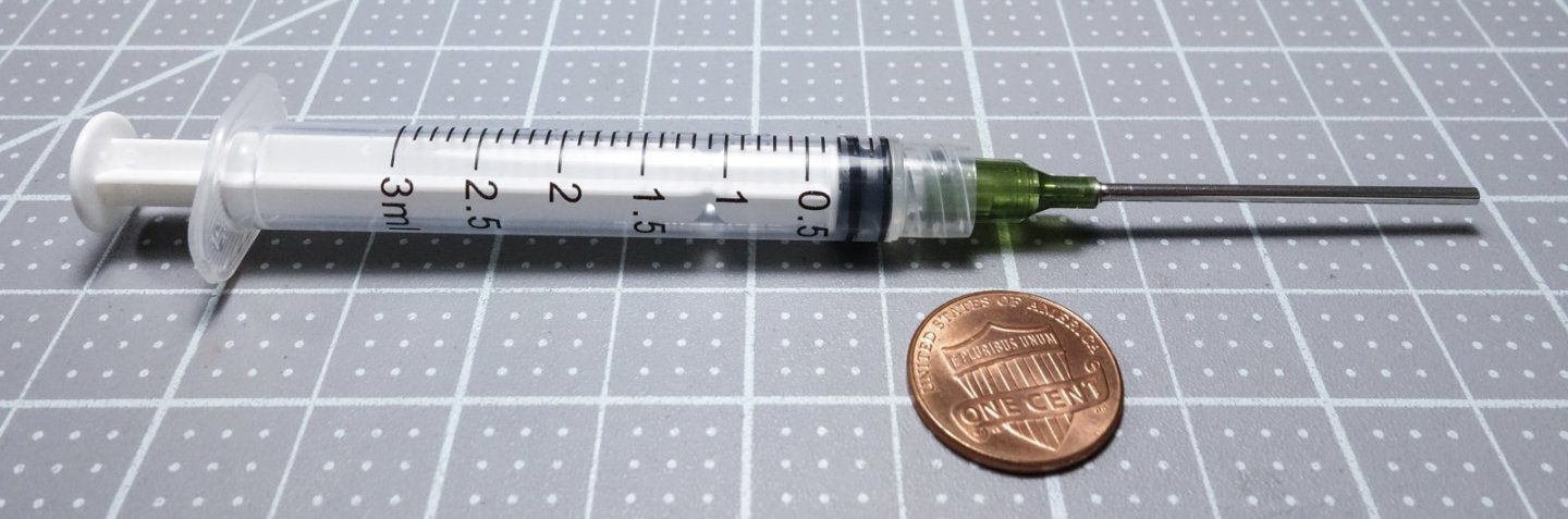
Gary, Jack, Glen, Keith B, Paul, John, Andy, Druxey, Keith A, Vaddoc, Tom, Eberhard and Eric - Thank you for your comments and kind words and thanks to all for the "thumbs up". As always, I so appreciate it. Thanks, somehow my junk box keeps offering up just what I'm looking for. HA! - It would look even more fishy with scale cod and haddock laying on top - but I'm not going there. Thanks, the ice turned out better than I thought it would. Sometimes you just get lucky, and everything falls together. It might be worth considering Andy, although I'm sure there are other good approaches. This holds together really well. I flipped the boat over and slapped the bottom repeatedly and only the scattered stray shards fell out, as desired. Everything else is now a single solid mass. I forgot to mention that the solution was applied with a syringe style dropper. Be aware that the solution is thin enough that it can run and soak areas where you don't want it. Needless to say, get a feel for it off-model first. It's easy Tom, the model railroaders have been doing this for ages to set gravel, dirt, mounds of coal, etc. But a wetting agent of some kind is key. There are two good sized hatches that will be open as well as one or several deck bunker plates. And it will be lit with LEDs. It's one of those situations where it's difficult to predict what will be visible through any one opening and view angle. But once the deck goes on, I'll have no opportunity to fix what I don't like or wish I had done better. Gary
-
Hello Vaddoc and congratulations on starting a new project. This is a vessel I once considered scratching myself, so I will certainly be following your progress with interest. The Hercules is a great choice and as you probably know, she is a US National Landmark and part of the San Francisco National Maritime Historical Park. Consequently, much is known about her. The vessel is part of HAER (Historic American Engineering Record) National Park Service. The drawings you have are public domain and the originals are available for download at various resolutions from the Library of Congress website. Also available at the site are photos, photo caption document, and a data document containing interesting stats and brief history. Steam Tug HERCULES, Hyde Street Pier, San Francisco, San Francisco County, CA (loc.gov) San Francisco Maritime National Historical Park (U.S. National Park Service) (nps.gov) The historic park also has a research center that may be of help to you. Maritime Research Center - San Francisco Maritime National Historical Park (U.S. National Park Service) (nps.gov) Best of luck on your new project. Gary
-
Glen, I agree with Rick and Keith - you do continue to amaze and your boats look sharp. But, I’m not sold on the idea of being able to fit 3 wee ants in a single boat - 2 maybe. Gary
- 235 replies
-
- 5
-
-
- Banshee II
- Bottle
- (and 1 more)
-
Very nice work, Andy. Thanks for the explanation of hawse and knighthead timbers, and the photos of the 1:1. Yes, they are indeed - big lumps of oak! Gary
- 174 replies
-
- 2
-
-
- Vigilance
- Sailing Trawler
- (and 1 more)
-
Fantastic work painting those figures, Eberhard. I noticed that even the officers’ buttons were painted! Really nice. Time to open another bottle of port. Gary
-
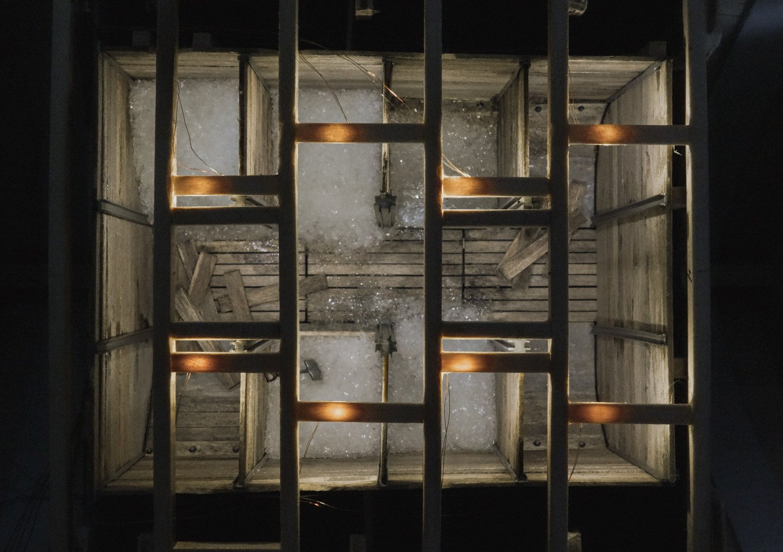
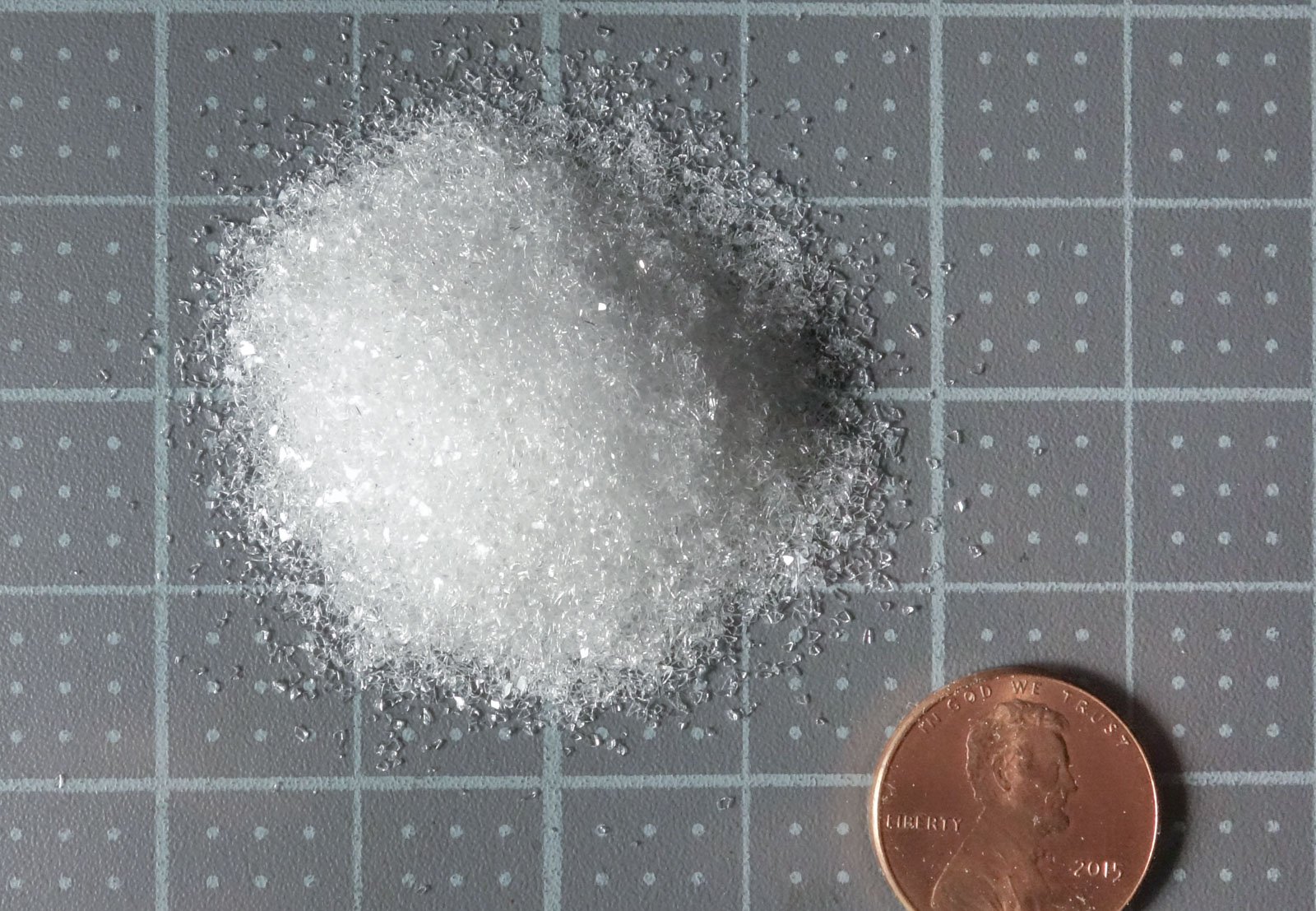
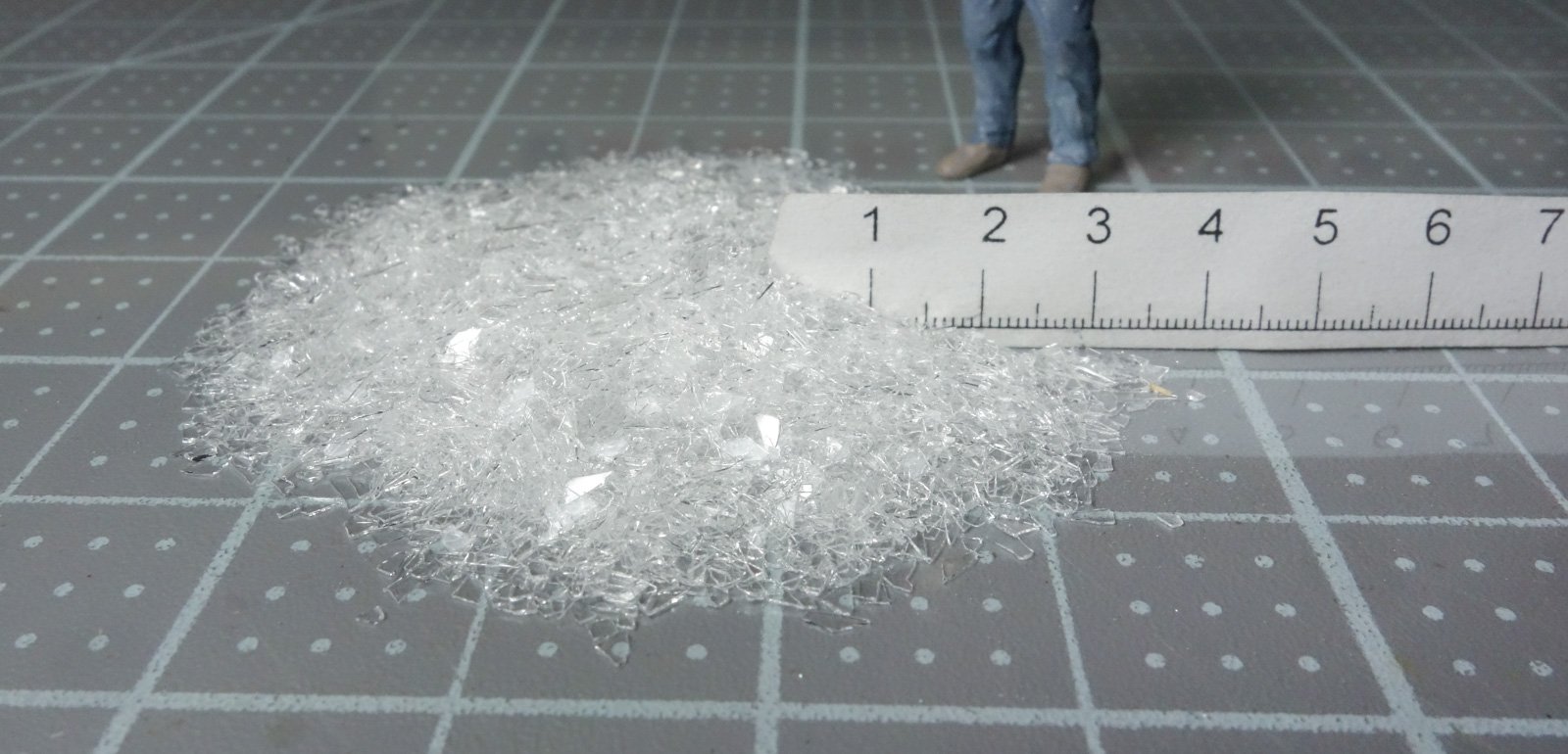
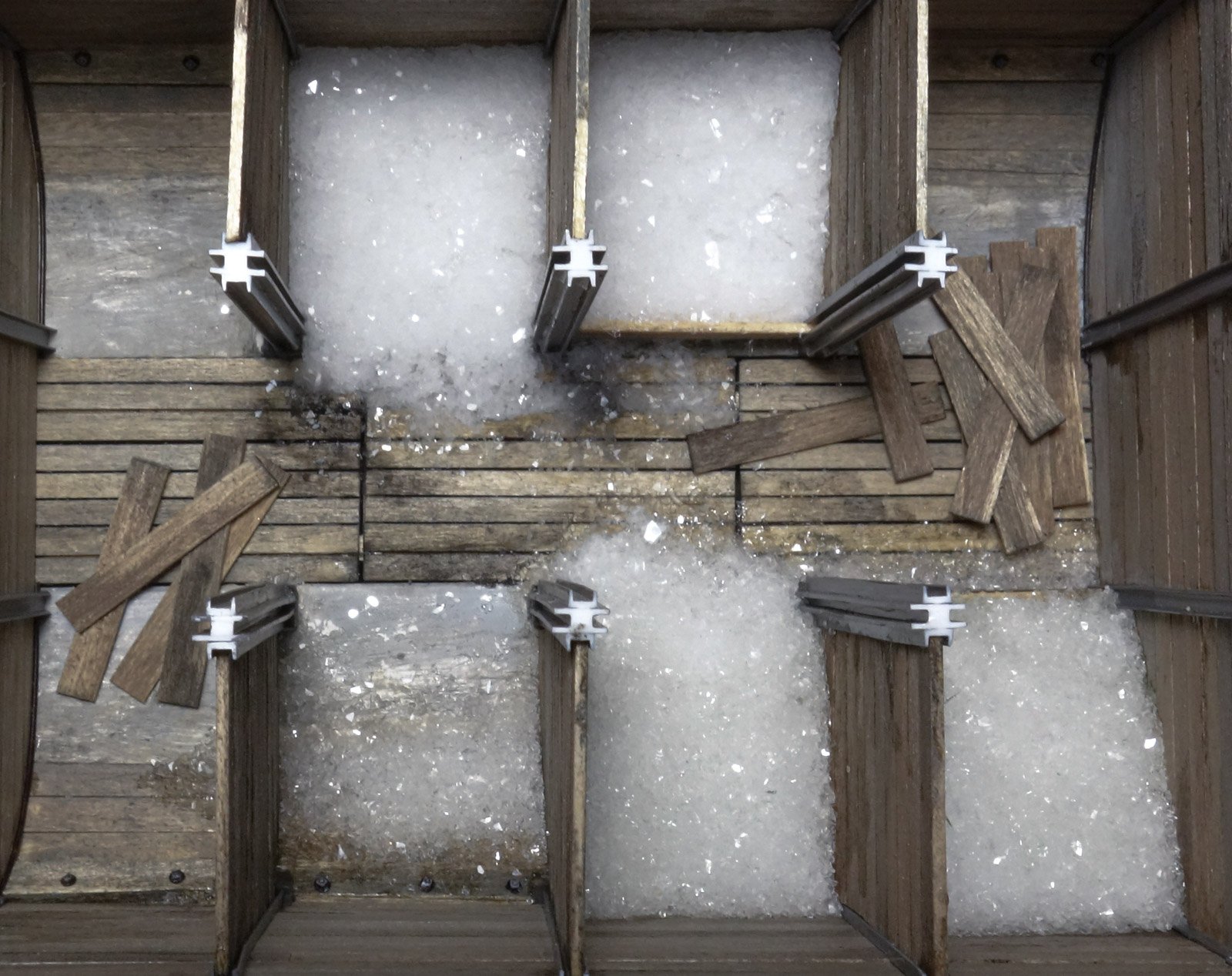
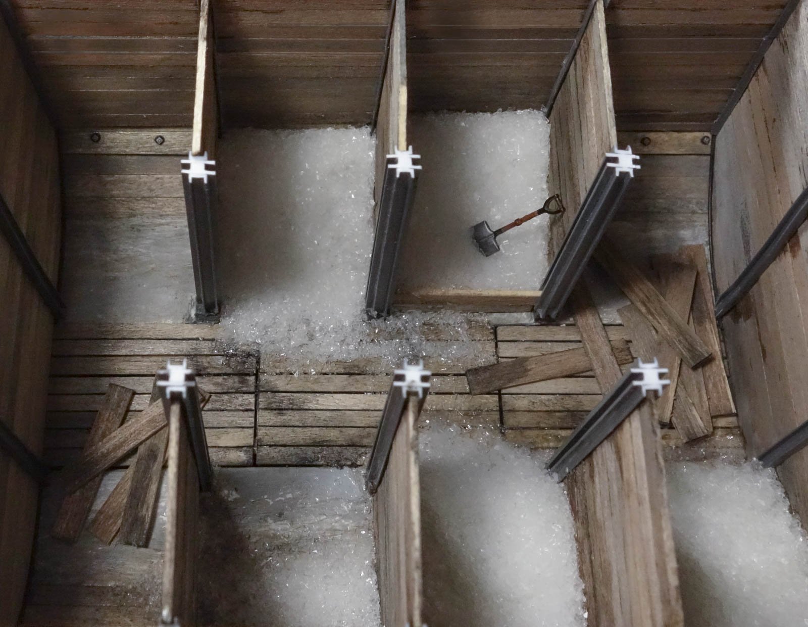
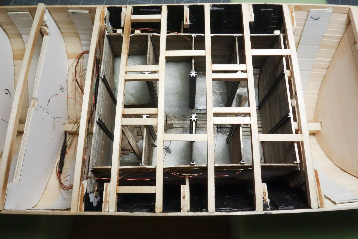
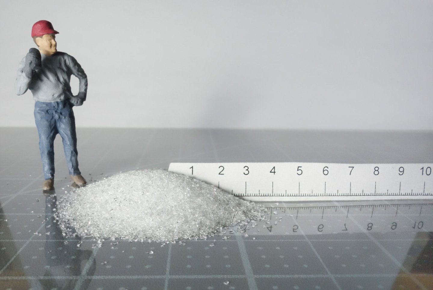
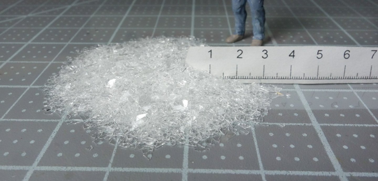
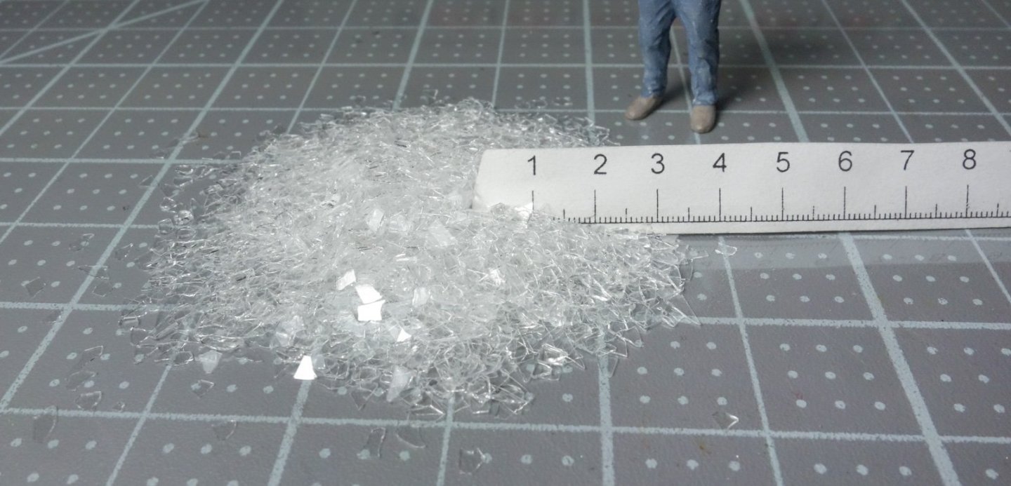
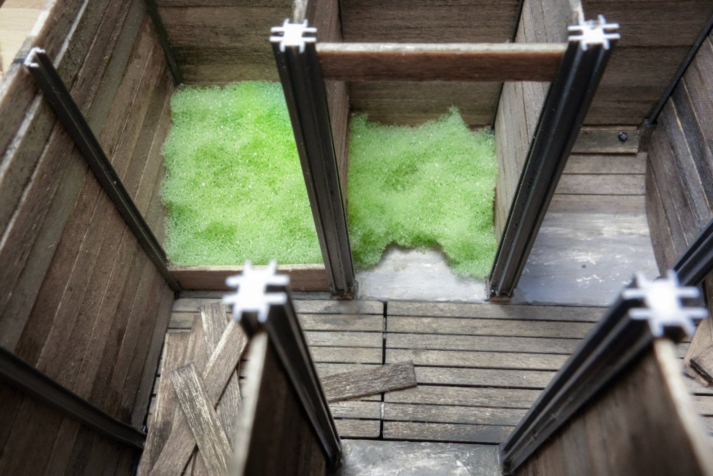
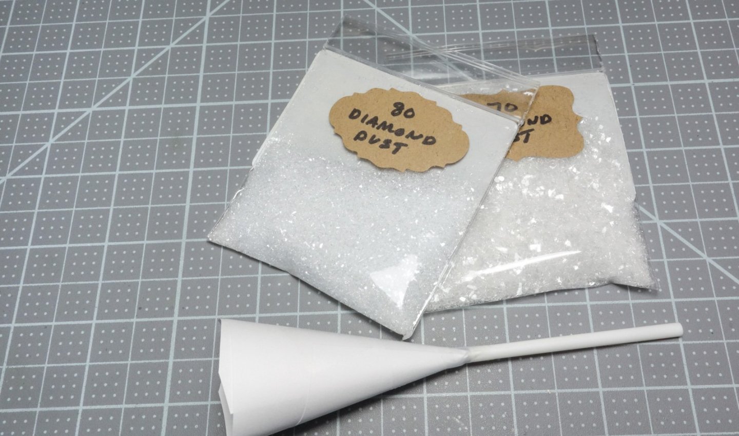
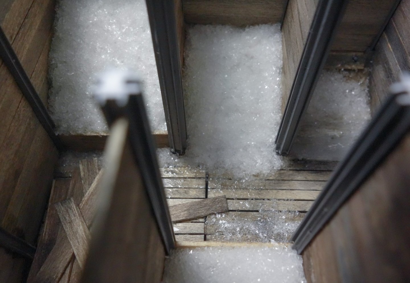
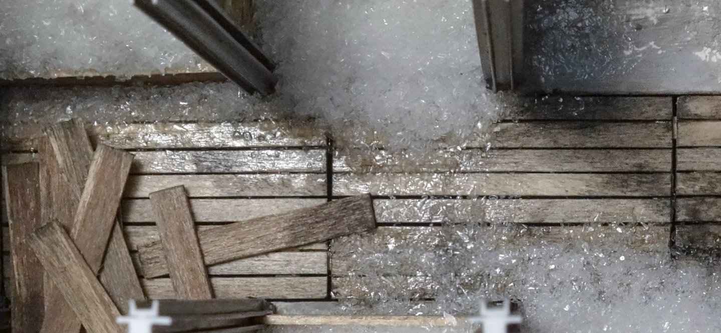
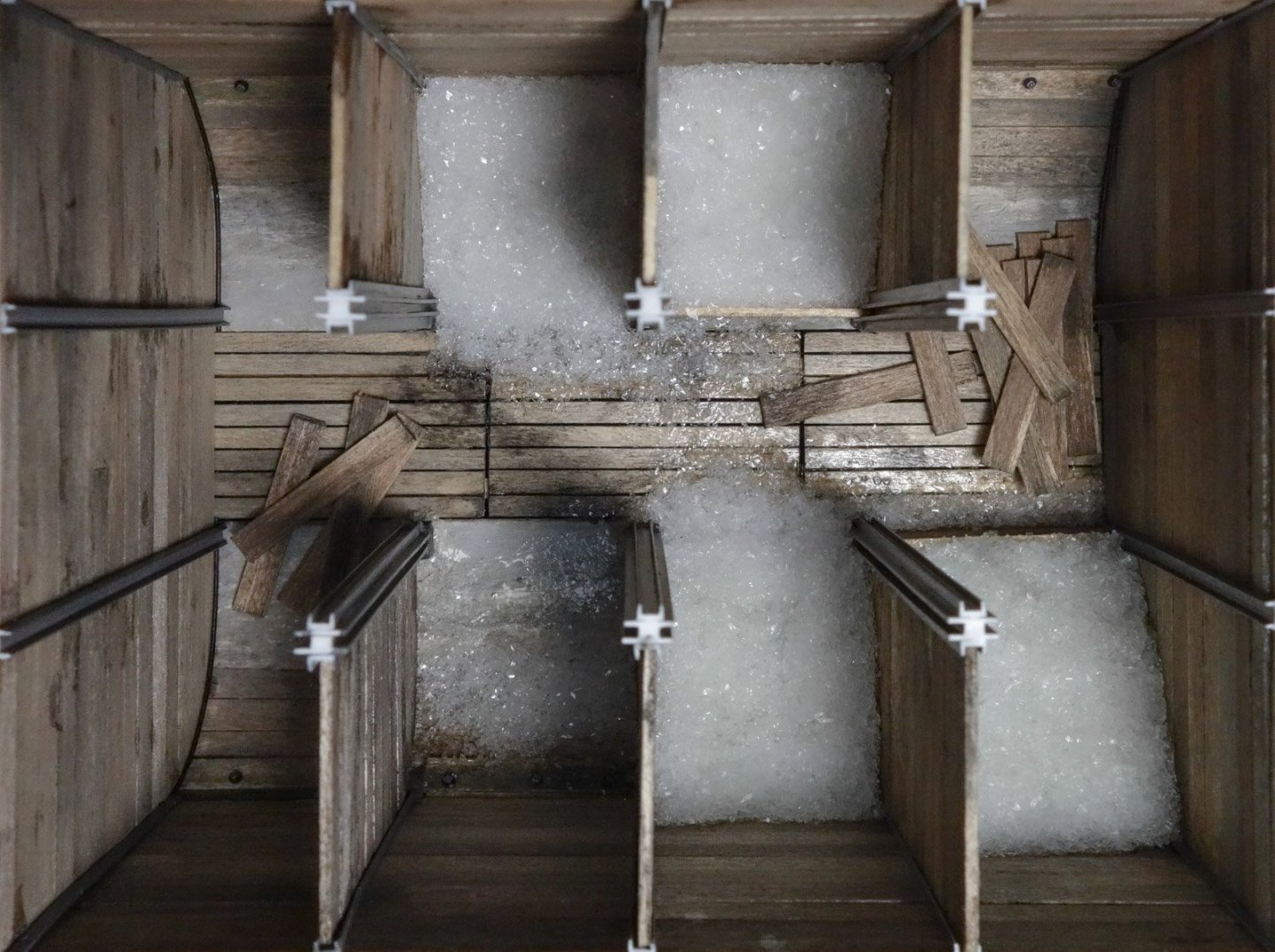
Greetings Fellow Modelers Thanks to all for the comments, "likes" and for taking a look. Completed Fish Hold I've been working on this model sporadically and at long last the fish hold is now done. Crushed/flaked ice has been added to the hold. The ice is ground glass and thanks go out to @wefalck and @FlyingFish for bringing this product to my attention. And I thank everyone who took the time to offer the helpful suggestions on this matter. I purchased 1oz. sample packs of different grits and the best match for the scale was 80 grit shown in the following two images. The paper rule is imperial in 1:48. This is what 70 grit looks like, although I suspect the package was mislabeled and is actually 60 grit. And 50 grit. This would make great looking broken glass for smaller scales. This material has an insistent angle of repose, so in order to help define how it piles and slopes, I predefined the spaces with torn pieces of open-cell foam pushed into the bunkers. This also lessened the amount of material used. In fact, the 1oz. sample packet was more than I needed. I ended up using half of the 80 grit and just a portion (for size variation) of the 70 grit. A small paper funnel with an attached styrene tube makes placement easy and accurate. This particular ground glass can be found online marketed as “German Glitter Glass”. It is used by crafters to make things – glitter. And it certainly does do that. The material is fixed into place using a method I learned from model railroaders. I mixed up a solution of 50/50 water/PVA with a couple of drops of surfactant to break surface tension. I use a dishwasher rinse agent for this, but windshield washer fluid works great also – or even liquid soap. I also added a few drops of white acrylic paint and an ever so small amount of phthalo blue to keep it from leaning toward yellow. The image below is the result. The ground glass actually appears finer, but that is only because the solution is sort of milky and has taken much of the contrast out and the “in your face” sparkles. Granted, the photo below is darker than the one above, but that is the only difference. The close up below shows the floorboards have been darkened with India ink/alcohol to suggest wet wood. On top of that a light layer of a craft store product called Gallery Glass (crystal clear) was brushed on for a watery look. Finally, a little ink/alcohol in the bunkers above the ice (again as wet staining) and also here and there to add definition to areas of wood. The LED lighting I had previously placed will be reattached when the deck beams go on next. I'm glad to be climbing out of this smelly fish hold. Thanks for looking. Stay well. Gary


-
Such nice work, Paul. I'm really enjoying this log! Gary
- 201 replies
-
- 4
-
-
-
- Oyster Sharpie
- first scratch build
- (and 1 more)
-
Excellent progress, Glen! Great work on the masts and stacks. For what it's worth, so do I. When I first saw your ship's boats on the toothpicks, I thought - OMG, he's hollowing out short grain rice for the boats. I do believe those are the smallest basswood boats I've ever seen. Nicely done! Gary
- 235 replies
-
- 5
-
-
-
-
- Banshee II
- Bottle
- (and 1 more)