HOLIDAY DONATION DRIVE - SUPPORT MSW - DO YOUR PART TO KEEP THIS GREAT FORUM GOING! (Only 51 donations so far out of 49,000 members - C'mon guys!)
×


FriedClams
-
Posts
1,368 -
Joined
-
Last visited
Content Type
Profiles
Forums
Gallery
Events
Everything posted by FriedClams
-
 Some very nice (and I'm sure tedious) work on those blocks Vaddoc. Sounds like another 1:10 model in your future. Good to see forward progress on your Deben. Gary
 -
Extremely nice work on the woodwork Michael. As Pat has mentioned above, the grain really looks beautiful, especially now that the tung oil has been applied. Matching the grain pattern down through the individual door panels is an elegant touch. Gary
-
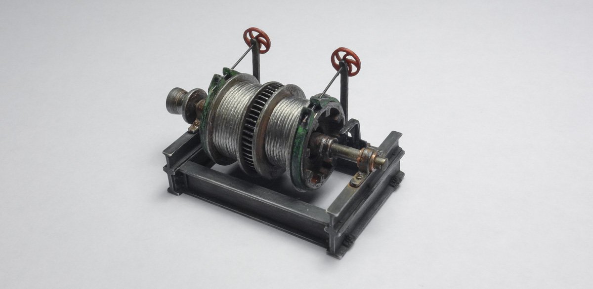
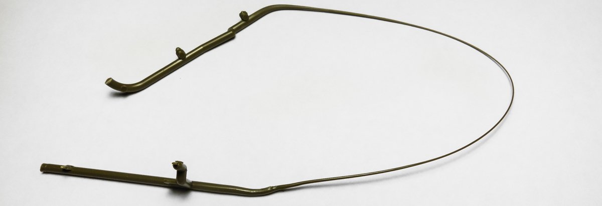
Hmmm… The brake rods scale to just over ½” (.57”) in 1:48, and now that I look at them more critically, they do look - scrawny. So I pulled them off, drilled out the hand wheels, brackets, etc. and installed .02” rod as replacements. This represents a rod with a diameter just under 1” (.96” or 24.38mm) which is more appropriate and I do like the looks of that much better. Good spot Wefalck and thanks for bringing it to my attention. Here is a before and after: Before And After. Also I added the clutch control levers. Facebook ? - I didn't know that. I'm one of the few people that doesn't have a Facebook account, so I don't get over there very often. But I'm glad you found my build log, welcome and thanks for the kind words. I don’t recall the actual Kelvin value of that LED but 4800k rings a bell. I usually end up color tinting the LEDs so I like to start with a color that is quite white. I have found it easier to tint a bright white LED warmer than the other way around. I color LEDs by applying thinned acrylic paint directly onto the LED lense or by changing the tint of the "glass" that surrounds it. For this mast light, I painted the LED directly, leaving the fixture glass clear. I agree with you that the color temperature in the photo is too cool - it's also too bright. For the photo I simply drove the LED at max forward voltage and the intensity of it totally overpowered the tinting I had applied. On the finished model the LED will be much dimmer and the tinting will be able to reassert its influence - I hope. Thanks for your comment Bedford and for the observation. Gary

- 424 replies
-
- 21
-

-
Thanks for the info on your paint choices CDW. I have used Mr. Surfacer 500 and 1000, but I’ve never tried their paint line. I’ll have to check out their “metal color“ products as it clearly produces some excellent results, at least in your skilled hands. Enjoying your log - very nice work. Gary
-
Dang ! I just found this build and am I glad I did. Such an interesting model - I had no idea a kit like this even existed! You're doing a wonderful job in constructing it Ekis. The church turned out beautifully, so charming. I will be watching your progress on the medieval village. Gary
-
Wonderful work on building the radial CDW - so crisp and clean. The engine has a great look and feel due to your coloring skills - the tubing/manifold looks very realistic. I would be very interested to know your coloring process. I look forward to future updates. Gary
-
I know what you mean Ken. I don't know how many times I've been satisfied with my work one day, and the next day . . . not so much. I think you're wise in taking the time to get the batten locations and gun ports placed just so as it defines everything afterward. Your model is looking straight and true and progressing very nicely. I'm looking forward to future updates. Gary
- 238 replies
-
- 1
-
-
- sloop
- providence
- (and 1 more)
-
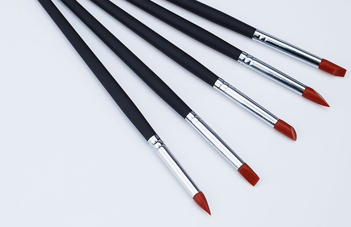
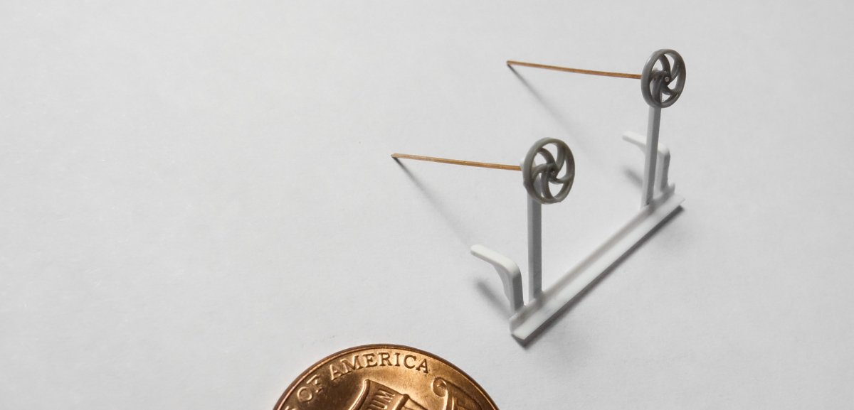
I want to thank everyone for the wonderful and generous comments on the winch. It's so nice to be able to share a hobby with like minded folks on such an amazing forum. And thanks to all for the likes and looking in. Hello Wefalck No threads for the hand wheel rods. I did try, but it's beyond my skill. The “rods” are .012” (.30mm) phosphor bronze and the closest I got to success was by giving the blackened wire a 180-degree twist inside a fold of 220 Emory cloth. But it looked - deliberately created rather than realistic. I always leave out what I can’t convincingly replicate if the detail isn't absolutely necessary. One negative can destroy the entire illusion. If this model was say - 1:24 instead of 1:48 then I would be compelled to try harder. I haven’t tried the 6B pencil for cast iron, although I will now - thanks for the tip. Highlighting “metal" with graphite is one of those techniques in modeling that never fails to impress me in how well it works. Using your finger to polish it works great, but have you tried one of these soft silicone brushes for tight areas and tiny work? It's magic and they are dirt cheap. And thanks for the suggestion of creating wire-rope by twisting small tinned copper wires togeather. A good idea. Thanks Gary
-
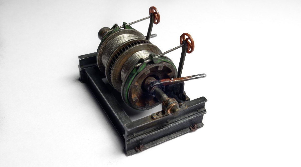
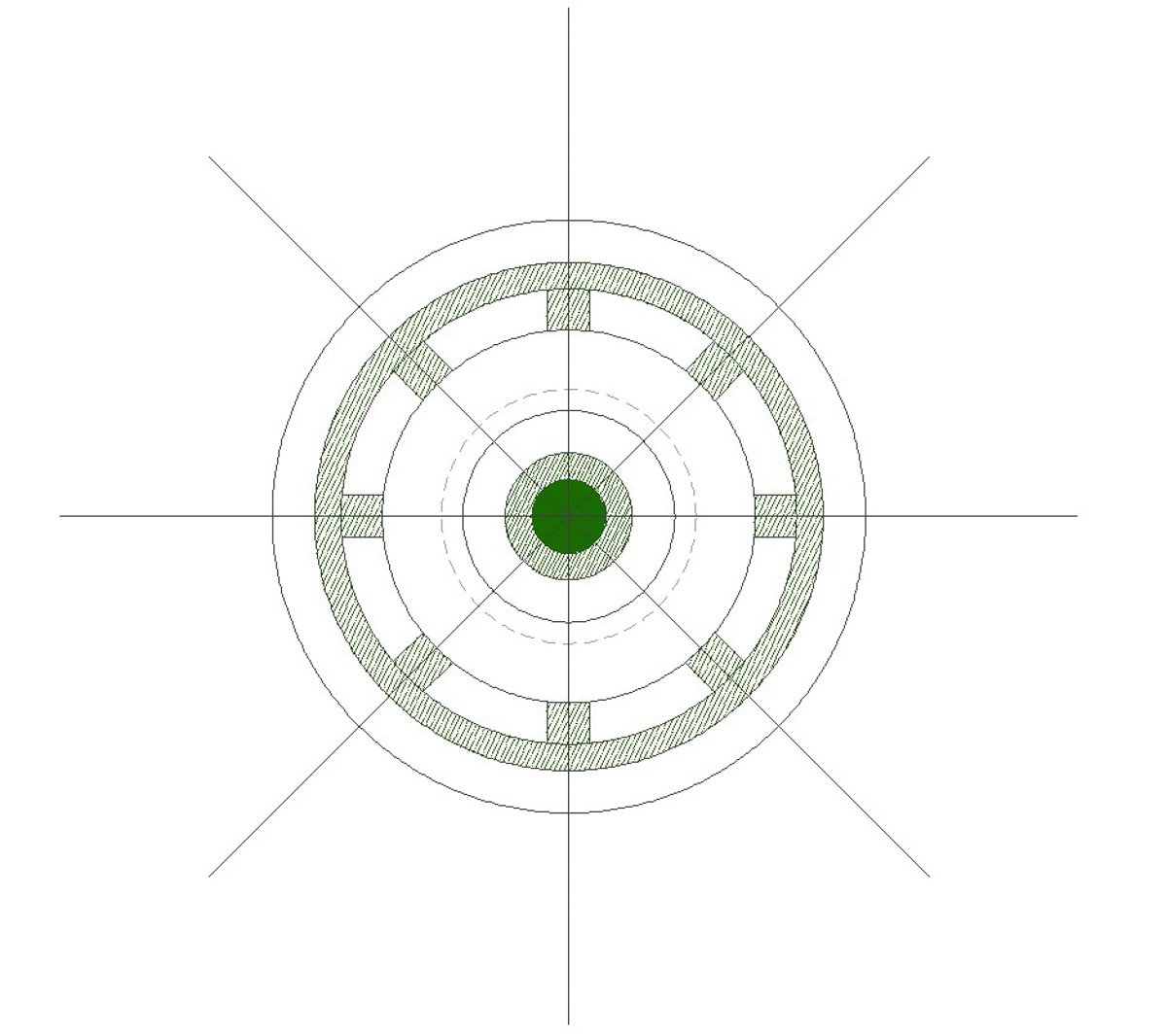
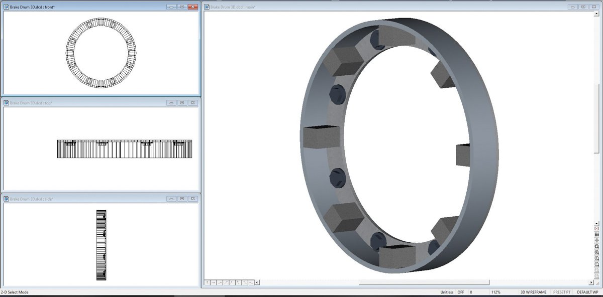
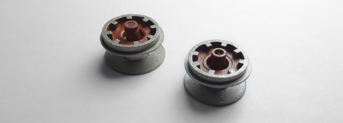
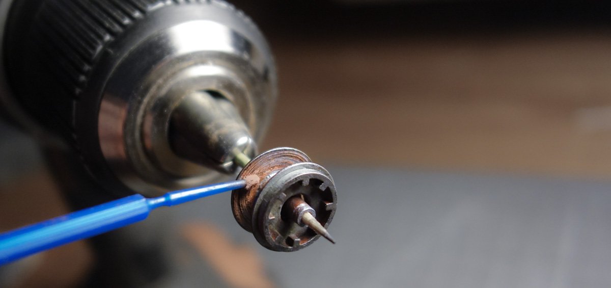
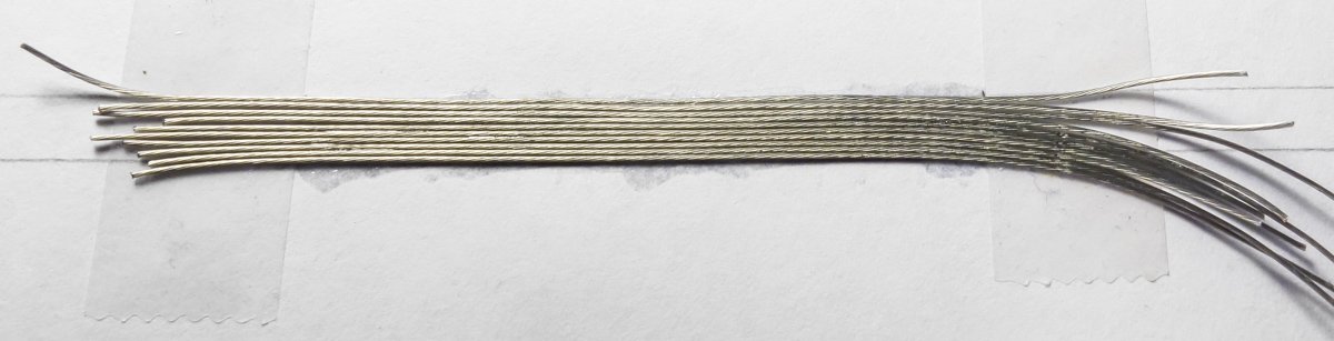
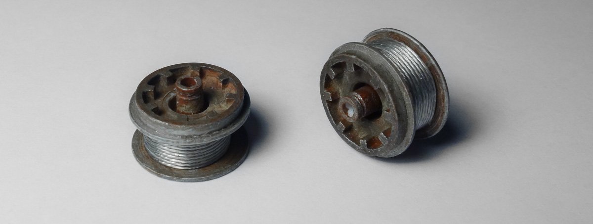
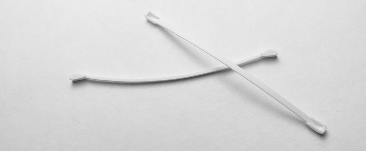
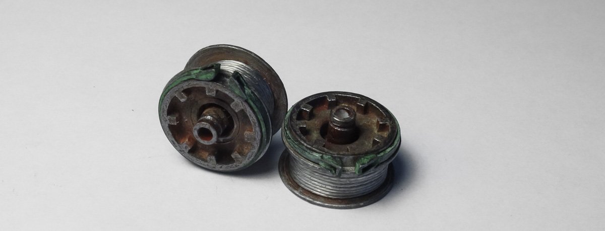
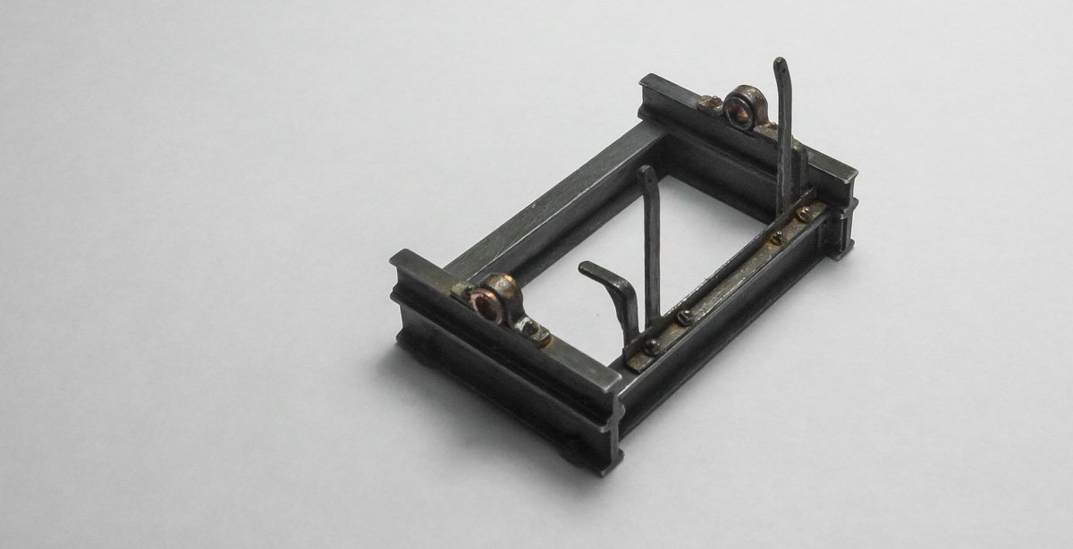
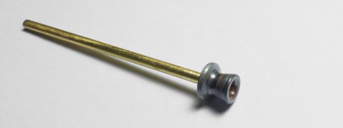
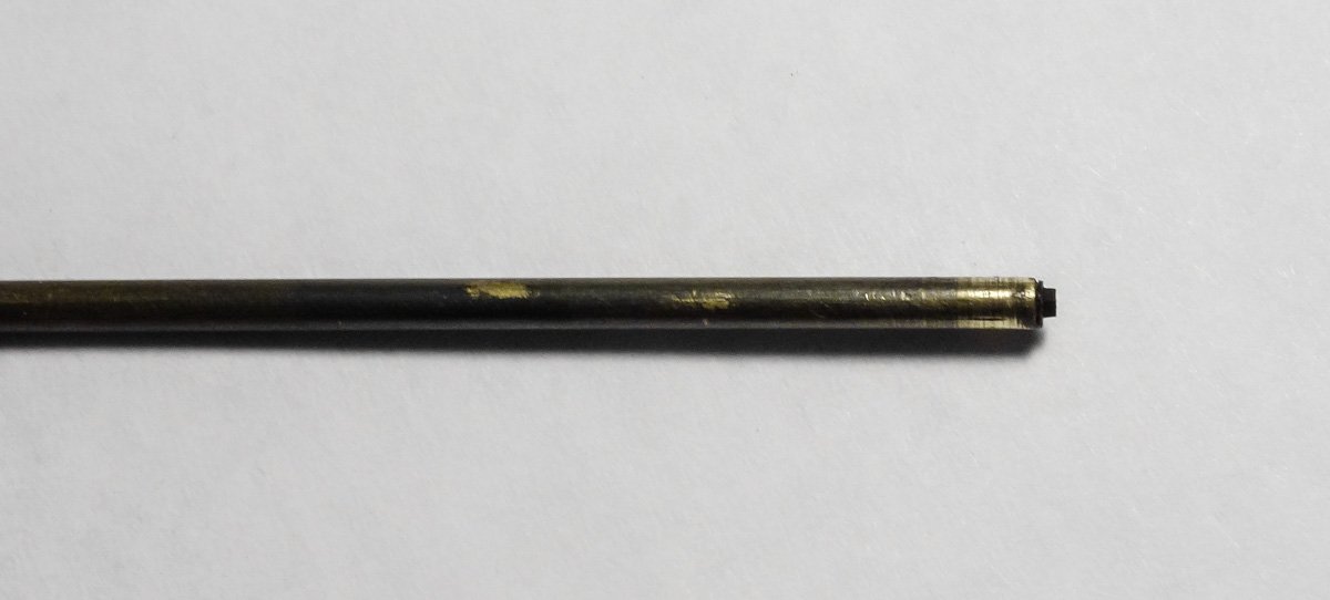
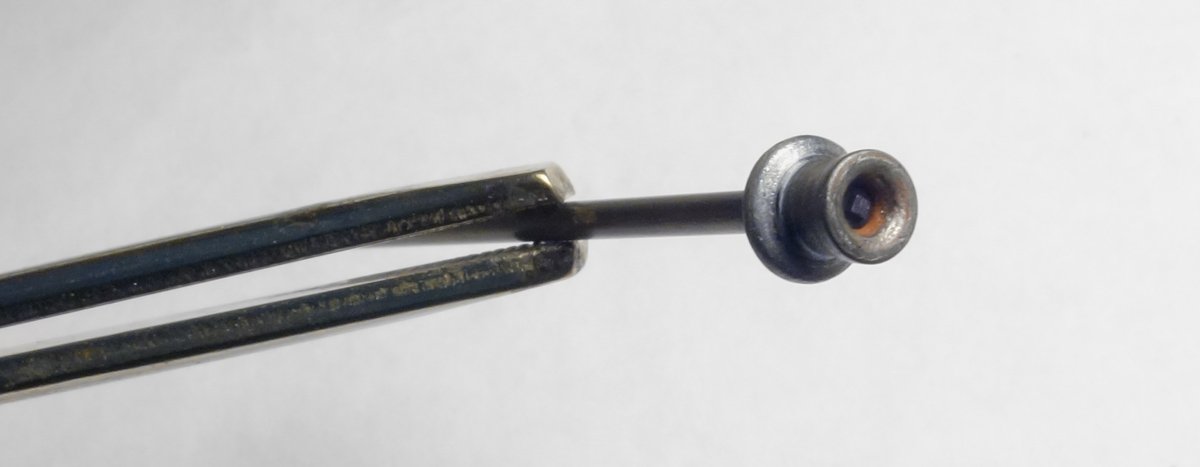
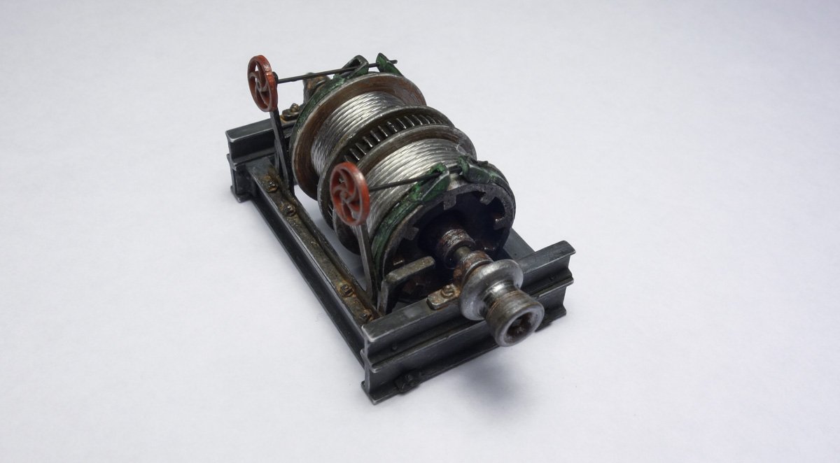
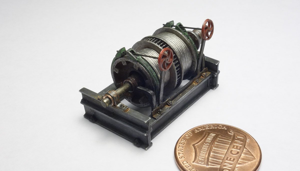
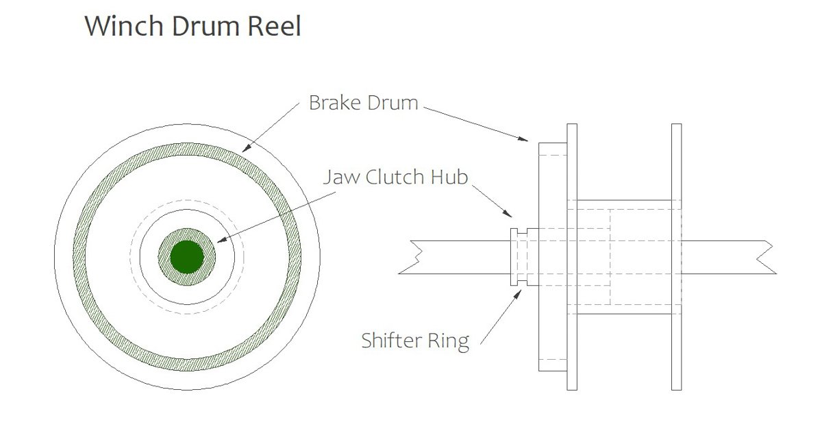
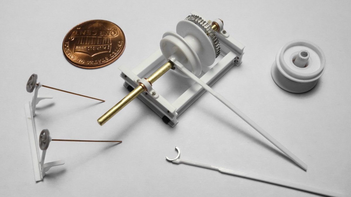
Thank you Keith, John, Druxey, Tom, Michael and Jim for your nice comments and encouragement - I truly appreciate it. And thanks for the likes and to those following along quietly. Thanks for the suggestion of the cup burrs Druxey - I didn't know there was such a tool. I couldn't find one small enough that would have worked in this instance, but I can see where they would come in very handy at other times. Thanks again and for the link. More Winch Stuff Progress on the trawl winch has been slow but inching forward just the same. The drum reels have already been made up from styrene but still needed to have the brake drum reinforcing segments added as shown below. Here is a 3D drawing screen shot of what the real brake drum would look like. This is my first stab at 3D CAD and the result is rudimentary and crude. I’ve done isometric projections before but not actual 3D constructions because I haven't found them terribly useful. But with advancements in 3D printing providing finer, crisper and more affordable parts, it’s an option I want to be prepared to take advantage of – and the printing technology is getting better all the time. Services are even available to print in wax for producing lost wax process metal components. But I’m a little conflicted about computer generating parts for a model, which is sort of strange as I have no problem using injection molded bits and pieces or white metal castings when it’s to my advantage – well, some other time. Some detail has been left out (back plate with bolt heads) because my circle cutter won’t go that small and I don't have a punch that size. The reels and drums were painted with enamel base colors after being cleaned in alcohol. I pushed the reels onto toothpicks and placed them in my portable hand drill to strip off some of the paint thickness and to scratch annular rings into faces of the reel surfaces. Pigment was applied hear and there. I wanted to wrap some wire cable into the reels as a separate piece from the cable and chain on the outer most layer that will travel out to the gallows frame. This lower cable will be clean and bright so a glimpse of it can be seen below the looser and rougher looking surface wrap when that eventually gets placed. Having the reel loaded with cable separately allows me to screw-up and rework the cable/chain leading to the gallows frame without having to rewind the reel itself. I’m using 7 strand stainless beading wire with a .019” diameter for the cable. Due to its stiffness, it resisted my every attempt at winding it onto the reels. So a simulation was in order. I first wrapped a strip of .010" styrene sheet repeatedly around the reel to build up the height. This was glued at every wrap. I then glued short lengths of the beading wire to a piece of paper (and to each other) in a width that would fit the reel opening. The wire slabs were cut to length, pre-bent around a ¼” dowel and popped onto the reels like wrist bracelets. Drum brake bands are made from .010” styrene. The bands are primed flat black enamel and sprinkled with green pigment power while still wet. Once totally dry, they were lightly sanded with 1500 paper for wear and then glued to the drums. Every sharp edge on these reel/drum assemblies was rubbed with the side of a #2 pencil. This helps define the outline of the shape and provides a metallic/chrome sort of sheen. The bracket frame for the hand wheels and clutch levers is glued to the winch frame. Some injection-molded nut/washers are glued on and the whole thing gets a base coat of black enamel primer. Several tones of grungy looking pigments are scrubbed in along with light rusting around some of the hardware. The main winch head is made from 1/4" dowel that is placed in the hand drill chuck and profiled with needle files. It was painted with silver over brown then spun in the drill, scratched with a pick and finally penciled. A washer and nut head is glued to the end of the main shaft. Then winch head is glued on. The main shaft, drum reels, bull gear and brake hand wheels are all glued into place. This winch is far from being done, but here’s what it looks like so far. Still left to do are the clutch shifters/levers; the sheet metal guard cover for the auxiliary winch head, the aux winch head itself; coloring touch-up, and other stuff that I’ve forgotten. Thanks for looking in. Gary
- 424 replies
-
- 32
-
-
Just catching up Maury. Your model is looking great and I like the process your using on the chain plates. Nice work. Gary
-
Beautiful job on the sail G.L. Looks like time well spent - it turned out great. I like your method of producing the thimbles. Very authentic looking. Gary
-
Splendid woodwork and machine work Michael - everything looks so very nice! Not a character flaw - a special personal attribute. And I thank you for doing so. Looking forward to what’s next. Gary
-
You have been busy modeling since your last postings in October and what beautiful modeling it is! Your davits and rail assembly are wonderfully made - an intimidating quantity of fragile pieces to solder up. Beautiful work Valeriy! Gary
-
Beautiful work Keith - every update is a treat. Thanks for sharing your process in detail. Gary
-
I have a dry quirky sense of humor Michael - I was just ribbing you about the screw slot orientation discussion. Gary
-
Nice re-do on the cabinet woodwork Michael, and they are beautiful just as I knew they would be. Very interesting discussion on the making of scale hinges, but aren't the screw slots supposed to be horizontal? Gary
-
Nice work on those plinths Keith and the completed bollards look great. I enjoy seeing your clever work methods and jigs to produce these small identical parts and the shroud brackets are another example of this. Great stuff. Gary
-
Very nice work on that outer planking Jim. It looks great and I'm sure it will sand/smooth up wonderfully. You may have to re-think painting it - a polished walnut surface would be beautiful. You're going after this model like it was your 30th build, not your 3rd. Impressive, keep it going! Gary
-
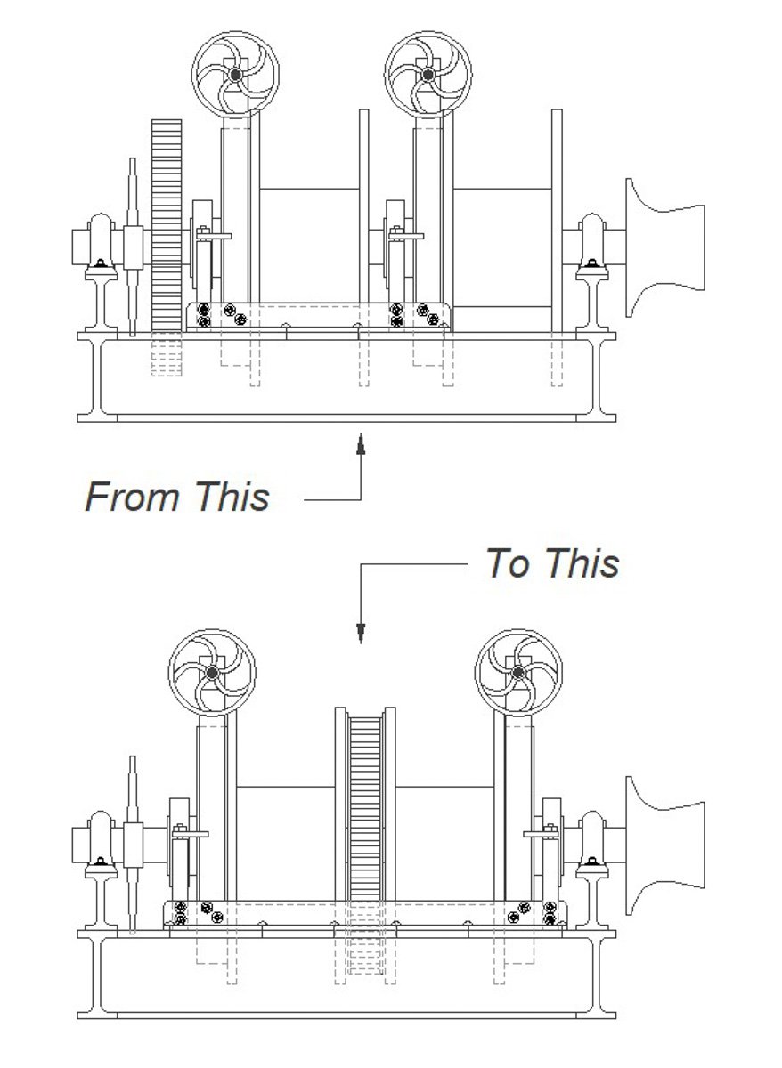
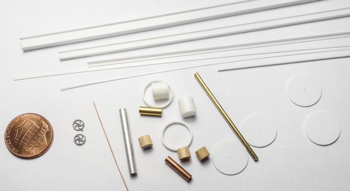
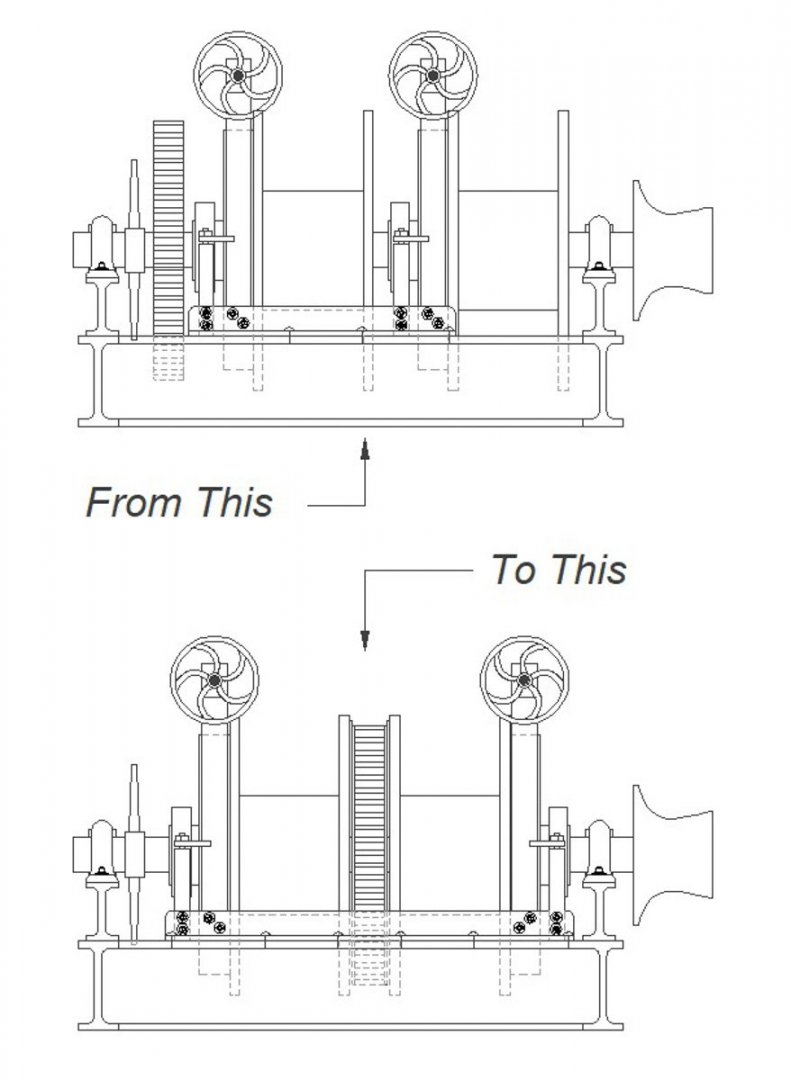
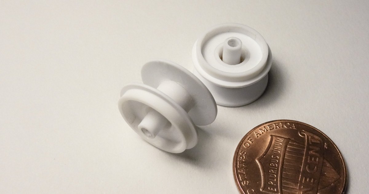
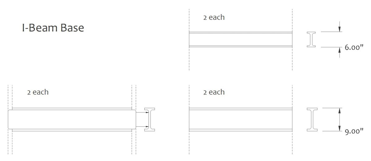
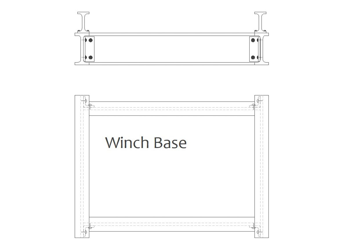
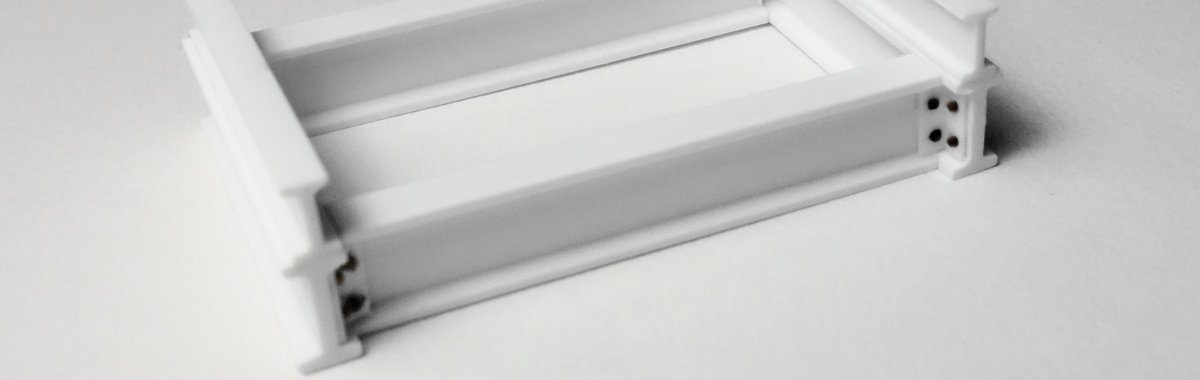
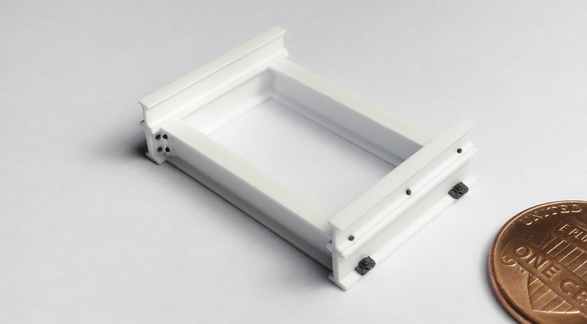
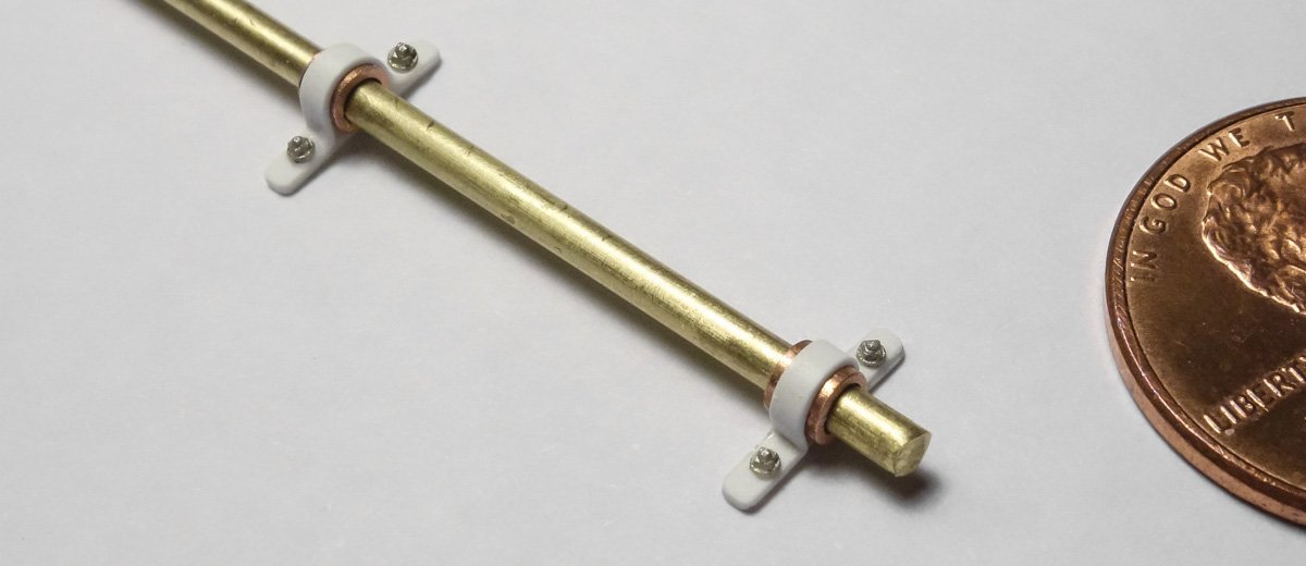
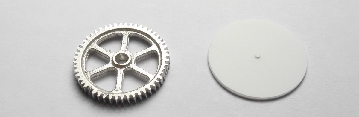
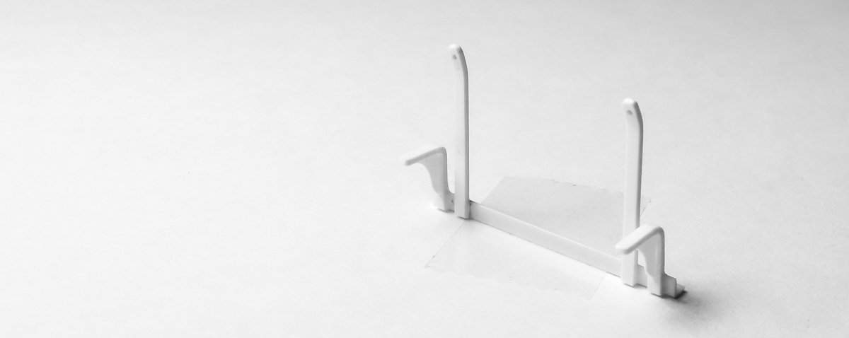
Thank you Johann and Hubert for visiting and the for kind comments. And as always, thanks to all for the likes and stopping by. Trawl Winch Continued Work on the trawl winch has been intermittent and slow, but here’s where it stands. Some of the materials for the main section of the winch are shown below. The round disks that will make up the drum reels were cut from .02” styrene sheet using a paper circle cutter. The two hand wheels are 1:87 boxcar brake wheels injection molded in Delrin. I decided to change the position of the bull gear from where I had it originally drawn. The gear has been moved from the end of the shaft to the center and now has a drum reel on either side. I did this after additional research convinced me this was by far the most common configuration of double drum winches regardless of time period. Once this fact penetrated my skull, I changed the drawings accordingly as shown below. The drawing below describes how the drum reels are assembled. I used solvent and CA gel to put these reels together - solvent when the pieces could be dry fit and gel where the parts were placed freehand and a brief window for position adjustment was needed. The shift ring slot will be cut later on. The base frame is made from six pieces of styrene “I” beams. Cutting templates are drawn and the pieces cut. The base frame construction is simple. The frame is simple, but placing and riveting the corner angle iron plates was time consuming. I didn’t have any injection molded rivets that were small enough for this application, but the detail is easy to simulate. A rivet in the 3/4" diameter range was needed, so I heat stretch some plastic sprue frame to the diameter required. I hold the piece of sprue over a flame and when the middle begins to slump, I pull it apart (stretch it) to a fine thread. Somewhere along the length of the stretch will be the diameter I need and a one-inch section is found that calipers at .015". Monofilament fishing line also works great for things like this if the right diameter is in your tackle box. The angle iron (and "I” beam) is styrene strip material from Evergreen. This structural shape material is a real time-saver if one of their available dimensions matches what you need. Here I’m using angle that is .060" (1.5mm) per side. That scales to 2.88" in 1:48 and is close enough to the 3" I was looking for. Now it’s just a matter of drilling holes into the angle iron, gluing the end of my stretched plastic into the hole and trimming it with a slight reveal sticking out. I use a piece of brass shim stock as a height gauge to trim them off. I could round over the heads with fine grit paper - but my sanity is more important. Some rivets were placed along the upper I-beams. Bolts and plate washers hold the base frame to the deck. Pillow block bearings are made from copper tube and .010" styrene. There are two layers of styrene, one under the bearing and another wrapped over the top. The main shaft is .070” diameter brass rod. In my parts stash I found this white metal gear. It is about the correct diameter and thickness for the bull gear so I’m going to use it as such. I cleaned it up and drilled out the hole for the shaft. The lower portion didn’t cast very well and is missing teeth, but I’ll rotate that to where it won’t be seen. A drum reel disc is shown as a relative size comparison. A section of angle iron will be bolted to the I-beam base to support brackets for the brake wheels and clutch engage levers. The brackets are made from .020” x .040" styrene. The clutch lever bracket gussets are .010” material. I’ve started on the clutch levers and yokes, but there is still a lot left to do - brake pads, pinion shaft, main winch head, frame and sheet metal guard for the auxiliary winch head, etc. And of course, the coloring and weathering. Thanks for stopping by. Gary
- 424 replies
-
- 24
-
-
Very nice Jean-Paul, she is coming along great. Clean work on the hull and the treenail simulation is very convincing. Gary
-
Really sweet work on those shock absorbers Keith - attach a gold chain and sell them as jewelry. Thanks for showing us your work process. Always such an interesting log read. Gary
-
Ouch! I’m surprised the backing sheet method didn’t work out as it seemed like a solid approach. The maple will certainly be beautiful and at least the design is already worked out. I agree. A few years back I bought a set of cabinet scrapers and the finish from them is so clean and the wood seems to have added depth. If you make a 1:8 sterling silver tea set - I’m going to throw away all my modeling stuff. Beautiful work Michael and a great build log. Gary
-
Nice job on the hand rails and the bridge walkway Kevin. She is looking great. Congratulations on your retirement - I wish you a happy and healthy one. Gary
- 337 replies
-
- 4
-
-
- finished
- mountfleet models
- (and 1 more)