HOLIDAY DONATION DRIVE - SUPPORT MSW - DO YOUR PART TO KEEP THIS GREAT FORUM GOING! (Only 51 donations so far out of 49,000 members - C'mon guys!)
×


FriedClams
-
Posts
1,368 -
Joined
-
Last visited
Content Type
Profiles
Forums
Gallery
Events
Everything posted by FriedClams
-
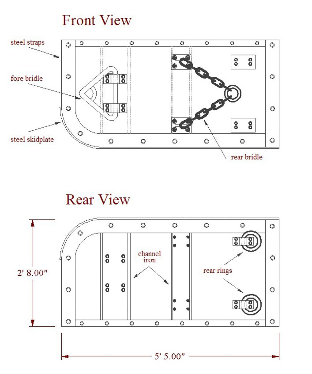
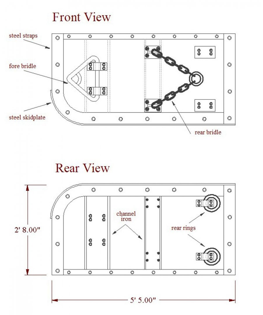
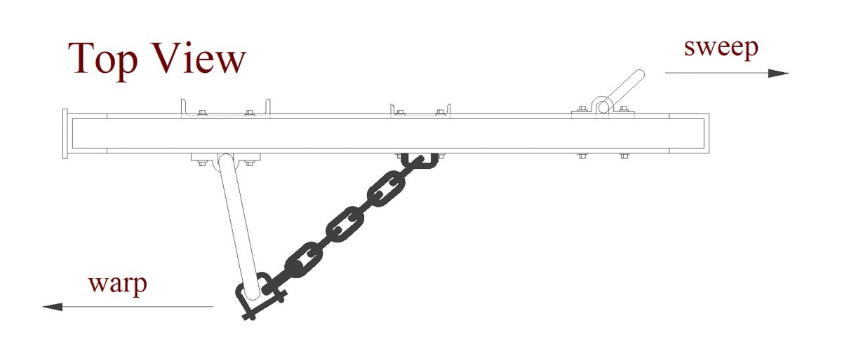
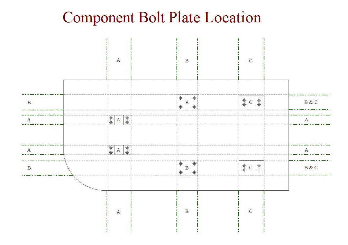
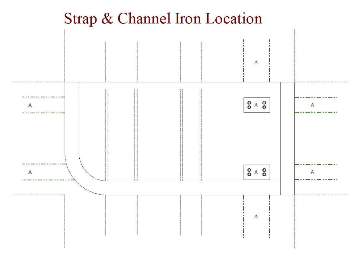
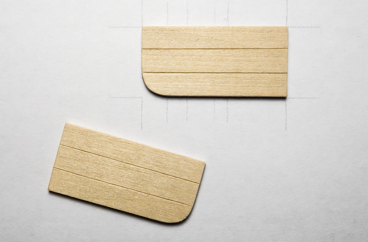
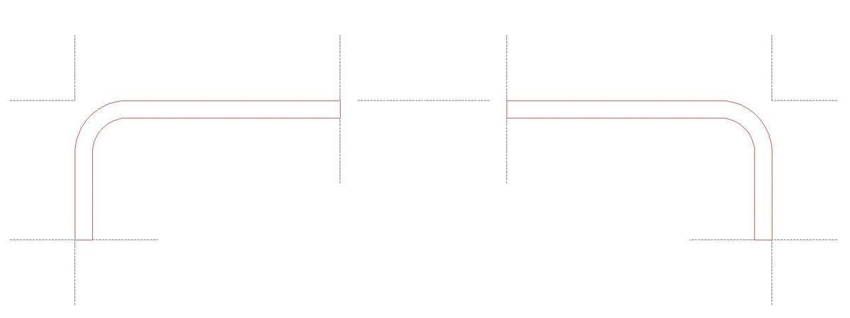
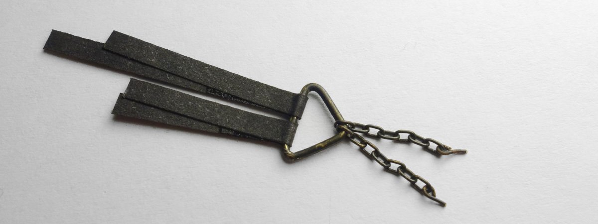
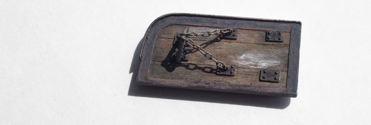
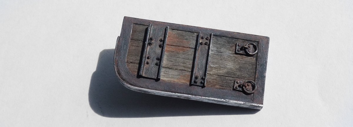
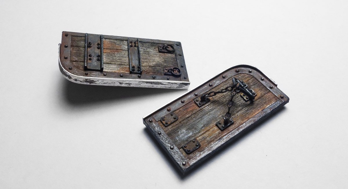
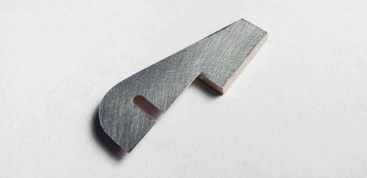
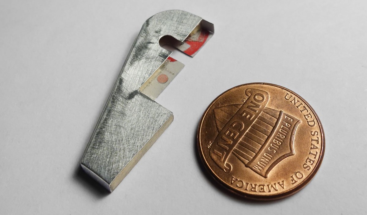
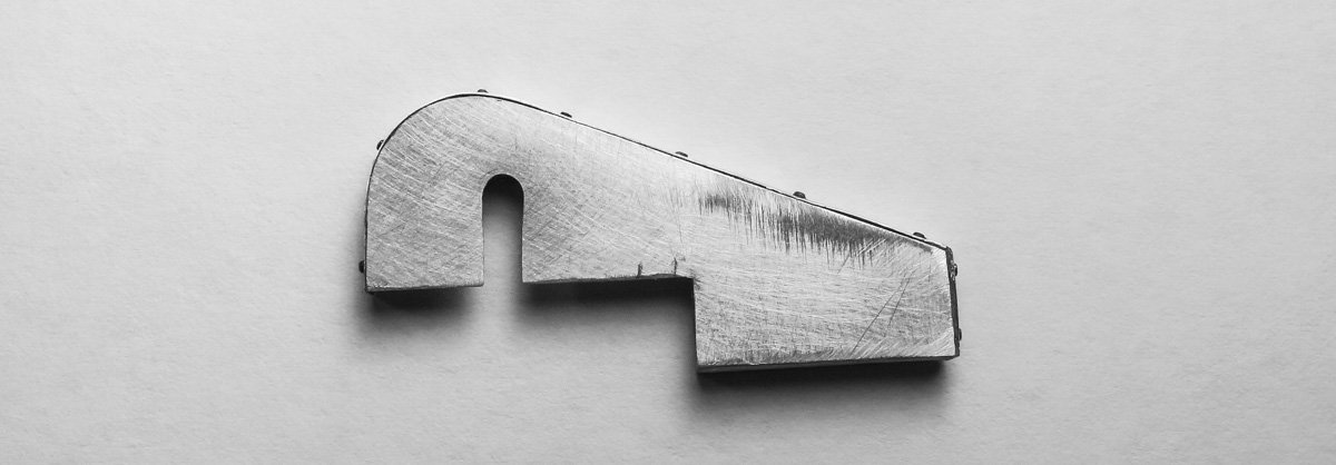
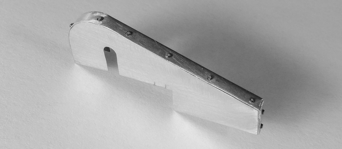
 Thanks to all for the nice comments, I really do appreciate them. And thanks for the likes and taking the time to visit my build log. It has been a while since my last posting and I hope you are all well and staying safe. After finishing the trawl winch, I tired of working on the model and dropped it like a dirty sock. Now after several weeks away from all modeling, it’s calling me back. Otter Boards Commercial fish trawling on its face seems like a static and unchanging technology, but it has evolved greatly over time. One of the most significant changes came with the invention of the “otter trawl". Otter trawling was developed in England and came to America around 1910. It derived its name from the otter board which was the name given to a sheering device that was being used for “hook and line” lake fishing in Ireland. This rectangular wood board would skate laterally across the waters’ surface and away from the direction it was being pulled. To some, the water disturbance caused by the board must have called to mind the activities of an otter. In commercial fishing, two otter boards are used together below the surface of the water to horizontally hold open the mouth of a trawl net. Like underwater kites, the otter boards are setup to push outward, away from each other, as the hydrodynamic pressure of moving water acts upon them. This was a major advancement over the “beam” trawl, which as the name implies requires a beam of some sort to keep the mouth of the net spread open. This beam arrangement severely limited the size of the trawl a single boat could tow. Otter boards used in ground fishing actually skid along the surface of the seabed. The noise this creates attracts fish and the turbidity helps to conceal the oncoming net. The fish become fatigued swimming out in front of the nets' cavernous mouth and eventually begin to fall back past a point of no return and end up in the “cod end”. The graphic below is from Seafish with text that I added. Otter boards are commonly referred to as “doors" and their design has been greatly improved over the years, but in the 1920s they were typically flat and made of wood. The doors in a trawling system work in equilibrium with drag from the net and pull from the boat. The doors have to be the right size and weight for the trawl net gear used, but the available horsepower of the towing vessel limits the size of the doors and how much hydrodynamic force can be applied to them. The doors end up as the pivot point between competing forces and have to accommodate both. It has been estimated that the doors account for about 1/4 of the total drag on the vessel. Because I have a boat of known horsepower, I can use the formula below from CIFT to determine the maximum square foot area of a single otter board based on tow HP. S=0.105P+4 This 45’ dragger is powered by a 100 HP engine, so... S = 0.105(100) + 4 = 14.5 sq ft. The rectangular ratio of 2 length x 1 height is commonly used to define the boards’ actual dimensions. Doing the math and rounding up gives dimensions of 5’5” x 2’8”. This is surprisingly close to the ballpark dimensions I estimated from photo scaling. W = 2.7P determines the optimum weight of a single wooden door based on tow HP. W=2.7(100) = 270lbs. Heavier perimeter strapping and a beefier iron skid plate can be added to increase the weight if required. So if I ever build a full-scale dragger in my back yard - I'll keep this in mind. My drawings below are based on documents from the 1940s and any photos of trawl doors I could find. The two doors will be identical except that they are mirror images of each other. I also draw part cutting and locating templates. The wood part of the doors is made from 1/16” basswood, providing a 3" scale board thickness. The wood is a single piece scribed to imitate individual boards. I’m using aluminum beverage can sidewall for the strapping and tin for the skid plates. This allows me to simulate seabed scraping by exposing the bright metal. I find this easier than trying to replicate bare metal with paint. To create the section of strapping with the radius that follows the forward edge of the door, I use a laser printer to transfer that shape to the aluminum. I first separate out the pieces in CAD to be used as templates. The image is printed on regular copy paper and ordinary cellophane tape is placed onto the templates. The sheet goes back into the printer and this time the image is transferred to the tape. The only reason for the first printing was to know where to place the tape. I peel the tape from the paper and stick it to the metal and cut it out. The tape transparency allows me to take advantage of the clean straight edge and square corner of the material. Clear laser printer labels would work great for this if you happen to have some lying around. All strapping and skid plates are glued on. The rear rings are made up from thin slices of .120” OD brass tube, which are held captive by a loop of annealed .014" brass wire. The back plate is cut from 1:87 rivet plate material and the diameter of the rivets are approximately tiny. I’m pretending that the rivets are actually the heads of bolts. The fore bridle is .032” brass rod and the rear chain is 15 links per inch. The paper clamps as you can see are yet untrimmed. Channel iron is glued into place using the drawing templates as a guide and injection molded nut/bolts are added. The channel iron is styrene strip “I” beams with one side sanded off. The rear rings are placed and some first attempts at color is added. The fore and rear bridles are placed along with the associated bolt plates. Thin CA is trickled down the chain links to help keep it from slumping. The rear ring plates are also glued on. Holes are drilled around the perimeter of the strapping and square nut heads are glued in. The wood was weathered with chalk and alcohol and the strapping is pigment over a base of flat black enamel. If I had to do this over, I would use blackened brass rather than the aluminum, as I’ve had to touch up the black enamel several times due to tiny flakes popping off from the constant handling. So once I finalized the color and was happy with the look, they were over sprayed with a clear flat coat to stabilize everything. A couple of items were intentionally left out for simplicity but mostly because of laziness - flat head screws holding the skid plates on and the tiny bolts for the thin upper strapping. I have never set foot on a commercial dragger, but building this model has given me a greater appreciation into how much skill and know-how is needed to bring in a catch of fresh fish. Describing what an otter board is and what it looks like is one thing, but being able to set it up and trim its attitude to work efficiently underwater is an art learned through years of experience and hard work. Suddenly, I’m hungry for fresh baked haddock with a slightly browned topping of panko and parmesan . . . Thanks for stopping by. Stay healthy. Gary
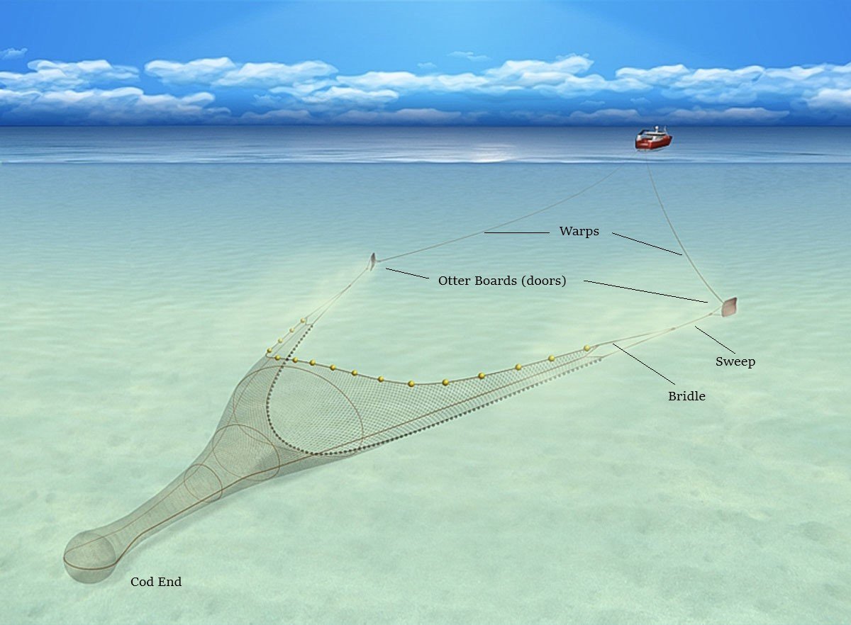

- 424 replies
-
- 30
-

-
Exquisite work - all of it. Everything is cut so cleanly and fits so perfectly. Gary
-
Congratulations Rob, she’s a beautiful model of an amazing ship. Excellent work. Gary
- 1,208 replies
-
- 2
-
-
- great republic
- clipper
- (and 1 more)
-
Beautiful model G.L. - congratulations. It has such an authentic look and feel to it. Very, very nice. And your log was a pleasure to follow. Gary
-
Nice to see an update on your model Jim - she’s looking good! Very nice result from the card stock caulking and I like the color contrasts of the various woods. Look forward to seeing the deck sanded and polished up. Gary
-
Wonderful progress on your model Keith. Splendid metal work and your approach to part making is always clever and well thought out. A pleasure catching up. Gary
-
Looking great G.L. The decking turned out very nice and the scarf joints in the gunwale and covering boards are a good looking detail. Always a pleasure catching up. Gary
-
I echo what others have already said but it’s worth repeating - beautiful cannon turnings, so clean and sharp. And I very much like the three new crew members. The painter looks like me, more paint on my clothes than on what I’m painting. Wonderful work Siggi. Looking forward to seeing the cannons cast. Gary
-
Such excellent work Wefalck. The laser cut paper produced a very nice result for the lower carriage. These specialty papers and materials you are using on this model are very interesting and something I must try at some future point. Thanks for providing the details of your process. The model is looking great and your log is always an enjoyable and educational read. Gary
-
Sweet work on the deckhouse and the brake portion of the anchor winches. Beautiful work Keith. Gary
-
Hello Keith, Good to see an update on the Tennessee - it’s a nice looking model. Sorry I can’t offer anything on the mystery object. It makes me think of a tank for compressed air. Hopefully someone will come up with an answer for you. Keep at it and keep healthy. Gary
-
Just catching up Kevin - very nice job you’re doing here. That was a tough call on the mast, but as others have said, it would have always bugged you. She is looking sweet ! Gary
- 337 replies
-
- 2
-
-
- finished
- mountfleet models
- (and 1 more)
-
Beautiful work Ekis. Your village is really coming along - nice work. I especially like the dusting on the statue and the half-timbering looks very authentic. Such a cool project! Gary
-
Just catching up CDW. Your aircraft turned out great - beautiful meticulous work. Love the clean details and the paint looks terrific. Very nice indeed. Gary
-
Such clean and beautiful work from every angle. The carvings are a true art. Wonderful. Gary
-
Thanks to all for the "likes" and for stopping by. Yes I know of the salt masking method, but I too have never tried it. I've seen it used often especially on 1:24 auto/truck hoods, roofs and the like to great effect. It seems like a method that would work best on larger areas. Another popular method and one that I have tried involves the use of hairspray as a soluble layer between non-soluble paint layers. This method has many variations and I have seen modelers apply it very convincingly indeed. I like using the glass cleaner method - it is effective and I feel in control of the final result. Here is a link to a forum thread (non shipbuilding) that describes the process. https://www.finescalerr.com/smf/index.php?topic=2165.0 Thanks for the comment Wefalck. And while I’m on the subject of rust I want to share a link to the website of Martin Heukeshoven. He builds rusty, derelict autos totally from scratch and as I understand, mostly from junk. They are large models – in the 60 to 130cm range and they are absolutely extraordinary. Click on the "Museum" link to access the individual models. The Ferrari sitting on the flat bed wrecker is my favorite. http://www.martin-heukeshoven.de/ I’m providing this second link directly to his galleries page. For some inexplicable reason the link to the "Museum” (gallery) does not appear on the home page when using my tablet. http://www.martin-heukeshoven.de/galerie A finer compliment can't be made. Thank you Druxey. You wouldn’t stay with me long Moab, I’m a ruthless and unbending taskmaster. Not really. Thanks for the kind words and I’m glad you’re finding something helpful here. Thanks Ken, thanks Jim. 1:48 is a pretty nice scale to work in. It’s large enough to allow for some detail, but not so large that you feel compelled to add a lot more. So I can fudge and omit details here that I couldn't at 1:24 or 1:12. The larger you go then more is expected. Thanks for your comments and I hope you are finding something useful here. Gary
-
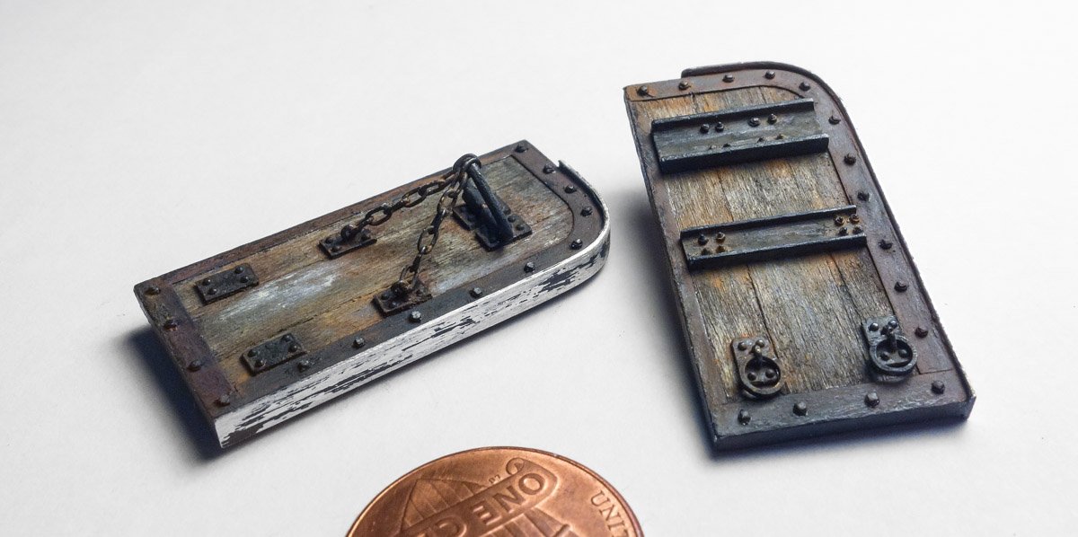
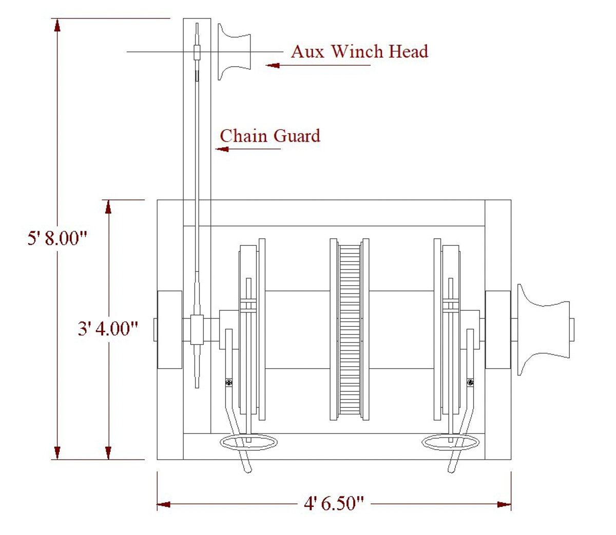
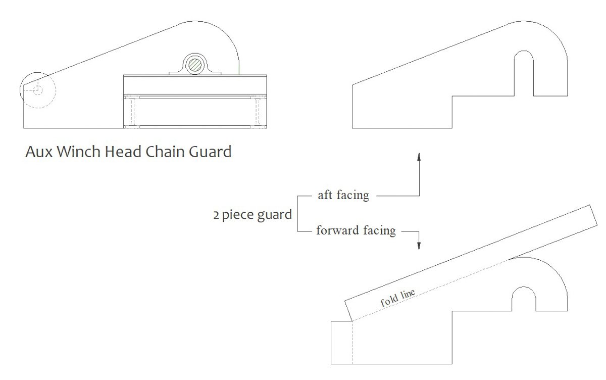
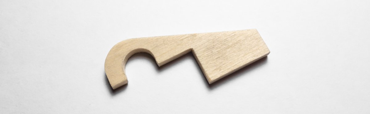
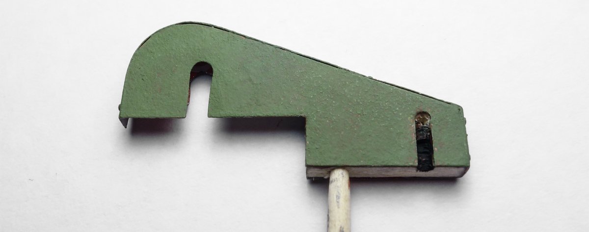
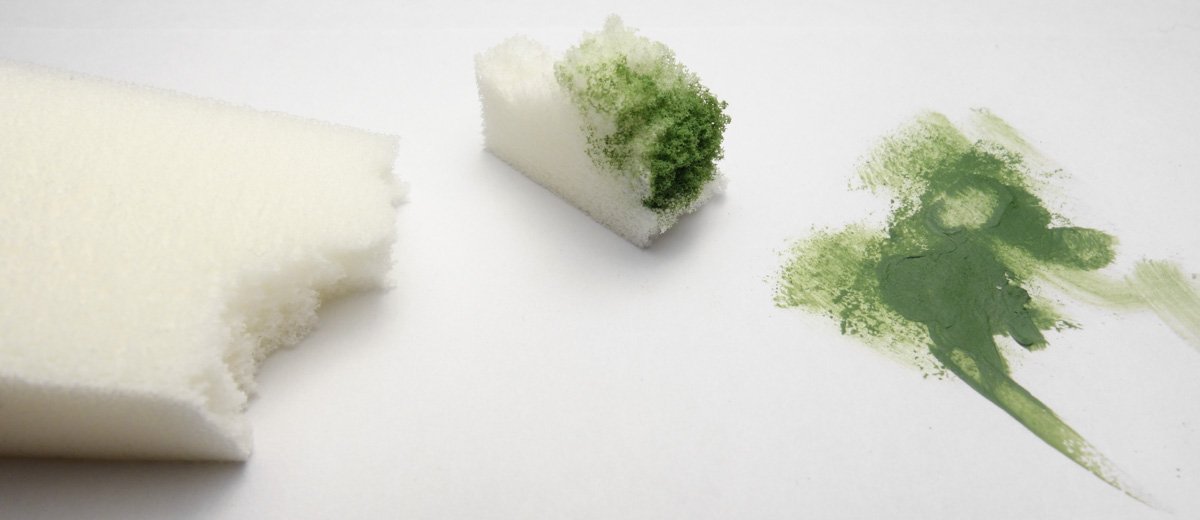
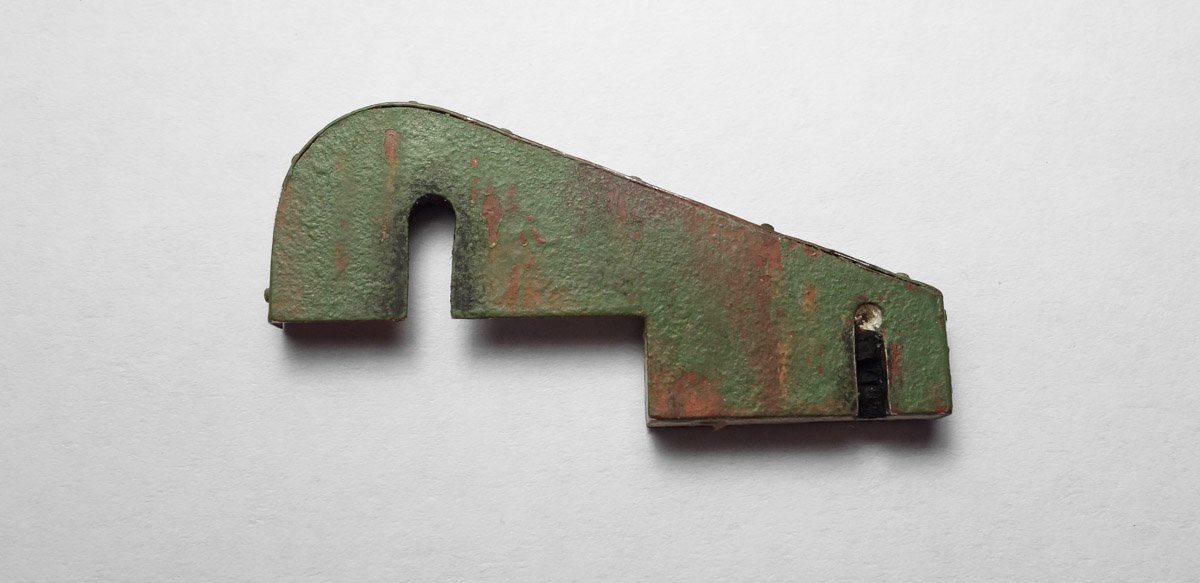
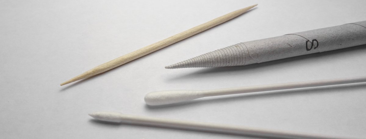
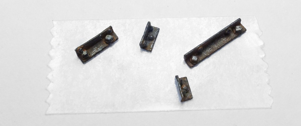
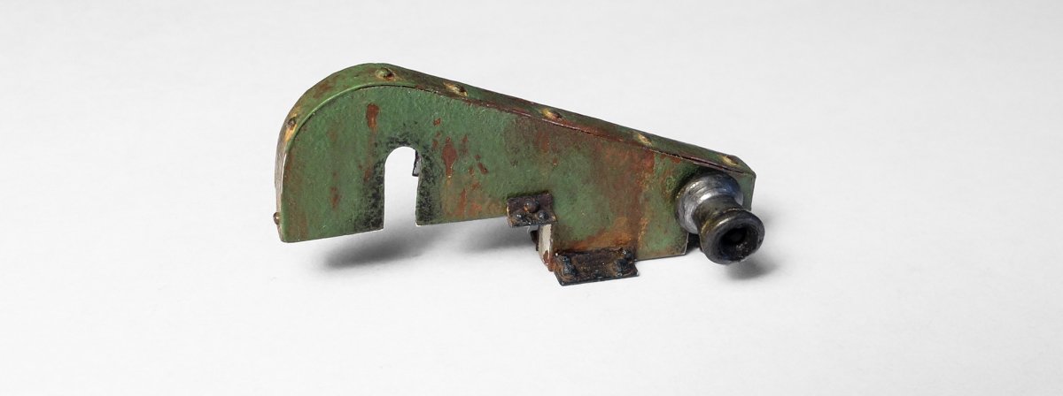
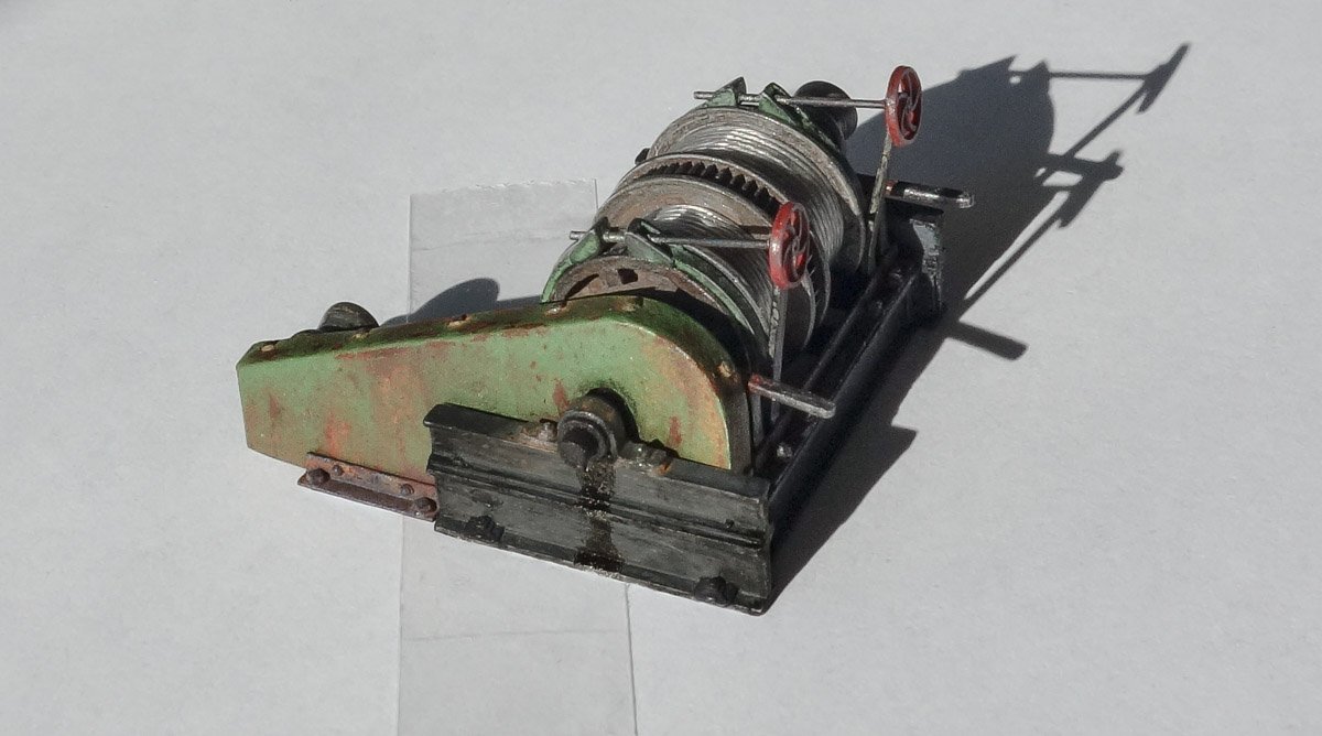
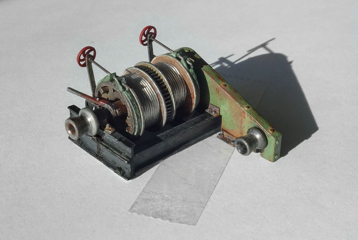
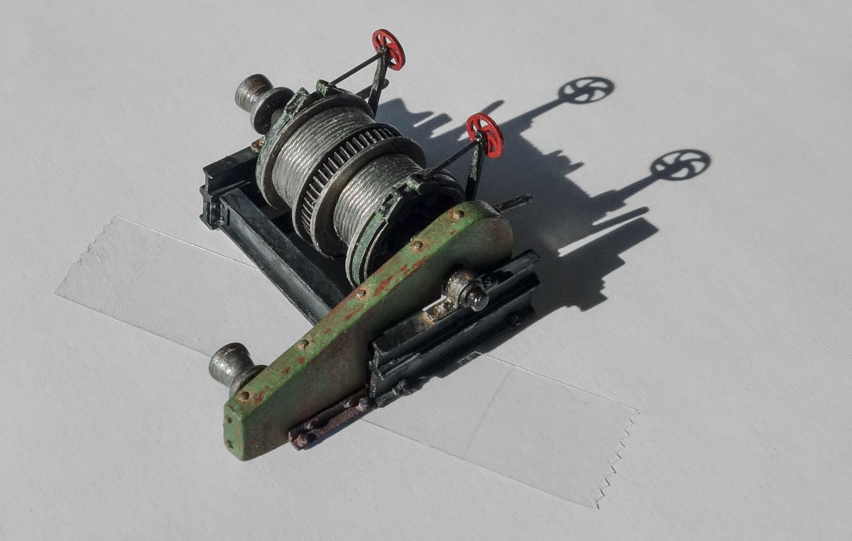
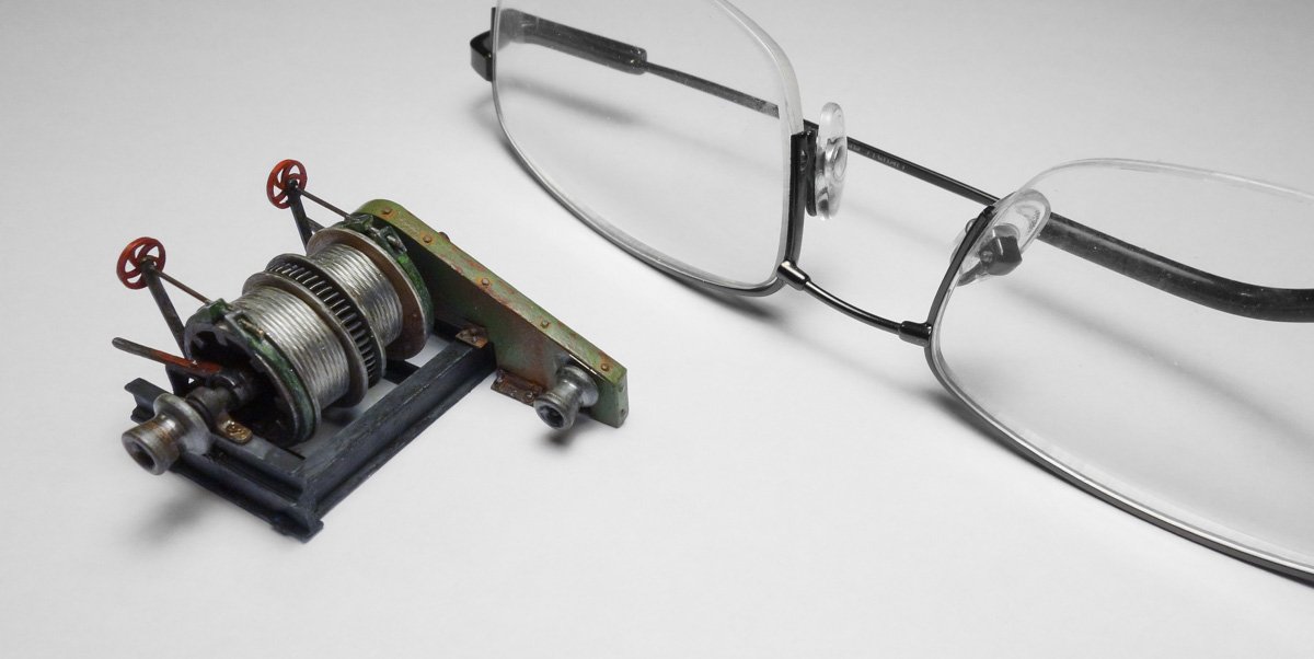
Thanks to all for the wonderful comments and input on the trawl winch - I very much appreciate it. And thanks for the likes and stopping by. Trawl Winch Chain Guard and Aux Winch Head The trawl winch has an auxiliary gypsy head that is smaller than the main head. It is driven off the main winch shaft via sprocket and roller chain as shown in the plan view drawing. The chain and sprocket will not be modeled, only the outer guard. The guard that encloses the chain is made up of two sections of sheet metal as shown below. The drawing will be used as a template for the two sections. I begin by cutting a pattern for the guard from basswood. The “sheet metal" sections will be glued to this wood pattern. I’m using aluminum cut from the sidewall of a beverage can for the guard. The material calipers to about .004" or .192” in 1:48. That is pretty stout and equivalent to about #6 gauge sheet steel, but it will have to do. I only care about material thickness because one section folds over the other and will reveal an edge being held down by sheet metal screws. I choose aluminum over something like foil because there are several places where the material is unsupported by the wood pattern and has to be stiff enough to stand on its own. Here is the aft side glued to the pattern. The aluminum had to be sanded to remove the coating that is sprayed to the inside of the can. Then the other side is glued on and the edge is wrapped over the top and sides. The thick edge is filed to a thinner profile and cap head style sheet screws with washers are placed along the edge. The injection-molded screws have a 1/8” long shank, so holes are drilled through the metal and glued into the wood pattern. The screws are actually holding the aluminum down and the material tends to behave like real sheet metal – tight down under the screws and lifting slightly between them. The color of most machine guards today is yellow – “Safety Yellow" to be exact. But in the 1920s, decades before OSHA, any color was acceptable if there was in fact a guard in place to paint. Having worked in industrial environments most of my life, I cringe to think of the working conditions of an earlier time with exposed whirling gears and spinning shafts right out in the open. How many poor workers just trying to make a living were entangled and maimed due to a single brief moment of inattention? Heartbreaking. Anyway, this chain guard will be green. Coloring the guard has a couple of steps, but each step is simple. To begin, the aluminum is sanded for tooth and then cleaned with alcohol. It is then painted with a rust colored enamel as a base and allowed to thoroughly dry over night. This base is smooth and I'll explain why I think that is important in a moment. Next, a coat of uninspiring dull green acrylic paint is applied.. A toothpick is used as a handle. Rather than using a brush or an airbrush, I used a cosmetic sponge for an uneven textured surface. These sponges have a pretty tight cellular structure and can be bought where women’s makeup is sold. After the acrylic has dried for about an hour, I wet small areas of the paint with water and give it a minute or two to soften the surface. I then start picking at it with a toothpick to remove chips of the acrylic paint, which reveals the rust colored enamel underneath. I then apply three different rust colored pigment powders that are mixed with water and brush applied individually to simulate general rusting/streaking. Black is also applied around the shaft slots to suggest grease sling. Finally, I scrub and blend the pigments (which has already been done in the image above) with one or several of the items shown below - a toothpick, artist stump or one of the excellent modeling swabs from Tamiya. The pigments I use (Bragdon) have a pressure activated adhesive component that sticks quite tenaciously when scrubbed on and doesn’t require a binder. So I didn’t apply a clear topcoat. Never sneeze into an open container of pigment. The reason I stated that the enamel base should be smooth is because it provides a textural contrast to the dabbed on acrylic overcoat. Once the acrylic is chipped off, not only does it leave a slight depression, but it also exposes a different texture layer, which emphasizes that the paint is actually missing and is not just a color illusion. Glancing sidelight shows this detail to great effect. And the uneven textured acrylic paint suggests rust might be forming just under the paint surface. These effects are not that noticeable at 1:48 but in larger scales with thicker paint and greater surface area being covered, they can be quite dramatic. The main idea is to have a base color that will not be affected by modifying a water-soluble upper layer. There are many techniques for model “paint chipping" and everyone seems to have a favorite. YouTube has videos on most of them. But if in the end the weathering turns out nasty, I can simply strip off the acrylic paint with water (and the pigments along with it) and leave the basecoat behind - ready for another go. The guard brackets are made from 1.5mm per side styrene angle with glued on injection molded nuts/washers from Grandt Line Products. Paint and pigment are applied. The aux winch head is made from 3/16” dowel, profiled with needle files, painted and penciled. Glued together. The shaft bearing drool is oil art paint. The good thing about oil is that it’s still workable days after it is put on - the bad thing is that it's still workable days after it is put on. The guard isn't glued to the winch yet so double-sided tape is used to hold it in place for the photos. The crown of the deck will dictate the final placement. I put in some brake shoe attachment point details and brackets to the underside which is impossible to see and therefore rather pointless. But they are there. I’ve left out a number of details. The most significant omission is the pinion gear and shaft that would be located a tad to one side and directly below the main shaft. It connects the bull gear to a drive source. It would be a challenge at this scale to include and would never be seen. There are a few things I don’t like about the trawl winch, but they go away when I stop looking at these close-up photos. So the winch is done and I’m anxious to move on. Thanks for looking in. Gary

- 424 replies
-
- 36
-
-
I look forward to following your progress on this dory. I love these small rugged little boats and the history behind them. It looks like a terrific kit and I wish you much success in your first build. Gary
- 30 replies
-
- 2
-
-
- grand banks dory
- model shipways
- (and 1 more)
-
Beautiful work - every bit of it. I especially like your anchors which are so precisely and cleanly made. Very nice indeed. Thanks for sharing your work with us. Gary
- 589 replies
-
- 2
-
-
- le gros ventre
- cargo
- (and 1 more)
-
This model is coming along wonderfully CDW, such careful and precise work. As others have mentioned, I too like your method of painting the inside of the clear canopy from the outside - very clever. A very informative and fun build to follow. Thanks for sharing it with us. Gary
-
The boats turned out extremely nice Kevin. I especially like the wrinkles and creases in the fabric covers. I would say the shrouds are steel cables. I scratch built a 1941 sardine carrier (70 ft LOA) and plans of the vessel called for 1/2” steel cable for the shrouds. That boat is about the same era as your trawler - so perhaps . . . I can’t say for certain about the davit winches, but every trawl winch or mine hoist or tugger I have ever seen winds/unwinds off the top of the drum, as in the first of your two illustrations. Keep up the great work. Gary
- 337 replies
-
- 3
-
-
- finished
- mountfleet models
- (and 1 more)
-
Dang ! You know what I mean ? Superb workmanship and a wonderful result Keith - just as I knew it would be. Such a concentration of complexity in so small a package. Wonderful. Gary
-
Nice diorama Clare - a charming scene. Good call on the boats. Yours are much more interesting and detailed than those shown on the box photo. Does the diorama get a base or surround? Good to see you back on the Kitamaebune. Gary