
HOLIDAY DONATION DRIVE - SUPPORT MSW - DO YOUR PART TO KEEP THIS GREAT FORUM GOING! (Only 51 donations so far out of 49,000 members - C'mon guys!)
×


FriedClams
-
Posts
1,368 -
Joined
-
Last visited
Content Type
Profiles
Forums
Gallery
Events
Everything posted by FriedClams
-
 Congratulations Eric on the completion of Arabia - she is beautiful. Your build log has been very educational and filled with interesting historical content. Thank you for sharing this rich and wonderful journey with us. I will be watching for your Viking longship build. Gary
- 599 replies
-
- 3
-

-
- sidewheeler
- arabia
- (and 4 more)
-
Interesting model Chris and you're doing a beautiful job. Nice clean work and I really like the interior framing at the stern and bow. Looking good! Gary
- 179 replies
-
- 4
-
-
- shipyard
- wütender hund
- (and 1 more)
-
Wonderful work Johann - beautiful. Gary
-
Just catching up Ekis and I see you have been busy. Your village is coming along great. This is such a fun build to follow. Thanks for sharing your progress with us. Gary
-
Deben is looking beautiful Vaddoc. Seems that you're not far from the finish line. I like all the rigging work that you've done - so neat and precise, just like the rest of the model. Great stuff. Gary
-
That's a sharp looking sharpie Jim - very nice tight work. It would be hard to tell it apart from a full sized version were it not for the clamps, ducks and other such items in the photos as a size reference. Splining the joinery for center board and rudder is a real craftsman's touch. Beautiful work. Gary
-
Wonderful work on the Arabia Eric. She's is looking very nice and I think your decision on the support base was a good one as the simple design keeps the viewer focused on the model itself. I love all the cargo details and they provide an authentic atmosphere. As John has stated above, I too appreciate your last post detailing the workings of the grasshopper poles. I knew how they worked in theory, but couldn't envision how it was actually done. Your log has been such an interesting read into the history of these riverboats. I had no idea how many variations on the basic design were used for different river conditions - stern vs sidewheel and so on. It's the history and story behind any given craft that brings a model of it to life. Looking forward to the final photo shoot. Gary
- 599 replies
-
- 5
-
-
- sidewheeler
- arabia
- (and 4 more)
-
Nice work on the deck and cockpit/cabin Jim. Beautiful tones in the wood and I really like the contrast of the lighter king plank to the rest of the deck. Looking real good. Gary
-
Excellent work Ken - your hull and planking look great. Nice progress. Gary
- 238 replies
-
- 1
-
-
- sloop
- providence
- (and 1 more)
-
Just catching up on your build Keith. And what do I find? The same old predictably perfect and wonderful craftsmanship of a true artist. Very - very nice. Gary
-
Excellent work on the 60 LB gun. Nice clean shape and edges - not easy to do in wood. Nicely detailed as well. The Harper’s Weekly page has to be a rare piece. It’s amazing to think that such a fragile piece of ephemera, something intended to last maybe a few months, has survived for 140 years and will now find a good home alongside your model. It’s in good condition too and will make a great complimentary display. Nice find. Your Tennessee is looking beautiful Keith. Gary
-
Hello and thanks to everyone for the kind words on the build. I really appreciate it. As to the concern for my whereabouts and well-being, I don’t quite know what to say except simply “thank you” for that concern. You are a wonderful and thoughtful group of people here at MSW. I've been busy doing mostly outdoor activities – hikes in the woods, bicycling, fishing, landscape photography and yes the dreaded yard work. But after being cooped up in the house for a few months, even yard work has a newfound appeal – well, sort of. I look forward to catching up on all your builds over the coming week or so and getting back to my own model. We are living in uncertain times with this on-going virus and I hope you are all well and doing what you can to protect yourself and those around you. Thanks again. Gary
- 424 replies
-
- 11
-
-
Great work Cajun. You're building a beautiful first model of a fine historic craft. Gary
-
Sweet progress on the Tennessee Keith - she is looking great and your stacks turned out very nice. That was a clever idea to place the support columns and stairs on the stack base - I like it. Waiting to see your approach on the deck guns. Nice looking craftsman era bungalow across the street from you. I love the older neighborhoods with the grass strips and old trees between the street and sidewalk. Granite curbstone? Does Ward and June Cleaver live next door? Gary
-
Excellent job on the skylights Keith, they look terrific. I especially like your work on the bar guarding. Repetitive, evenly spaced details like this require such precision as the eye will quickly pick out the slightest irregularity. Very nice work as always. Gary
-
Hello Patrick, it's good to see you back at the modeling bench. You can sure pack an amazing amount of detail into your tiny models. 1:388 - good grief man! Well considering that you're working at a sub-atomic level, they look darn good to me Patrick. They must be less than 5mm tall if I am calculating that correctly! I wouldn't even have the courage to try. Sapphire is looking really great and I look forward to more updates. Gary
-
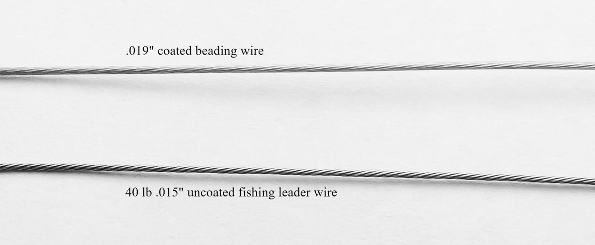
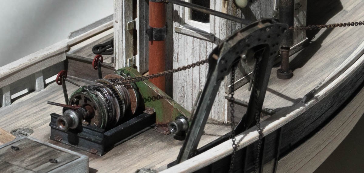
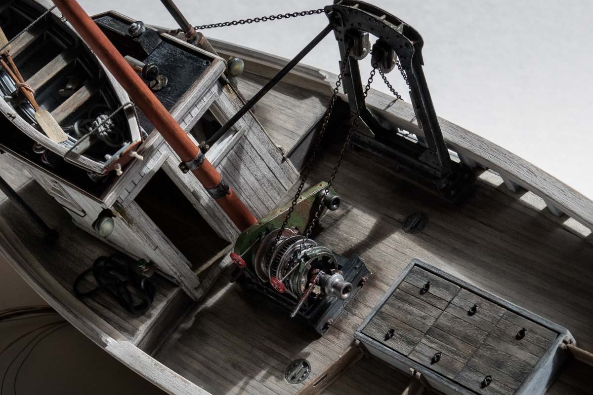
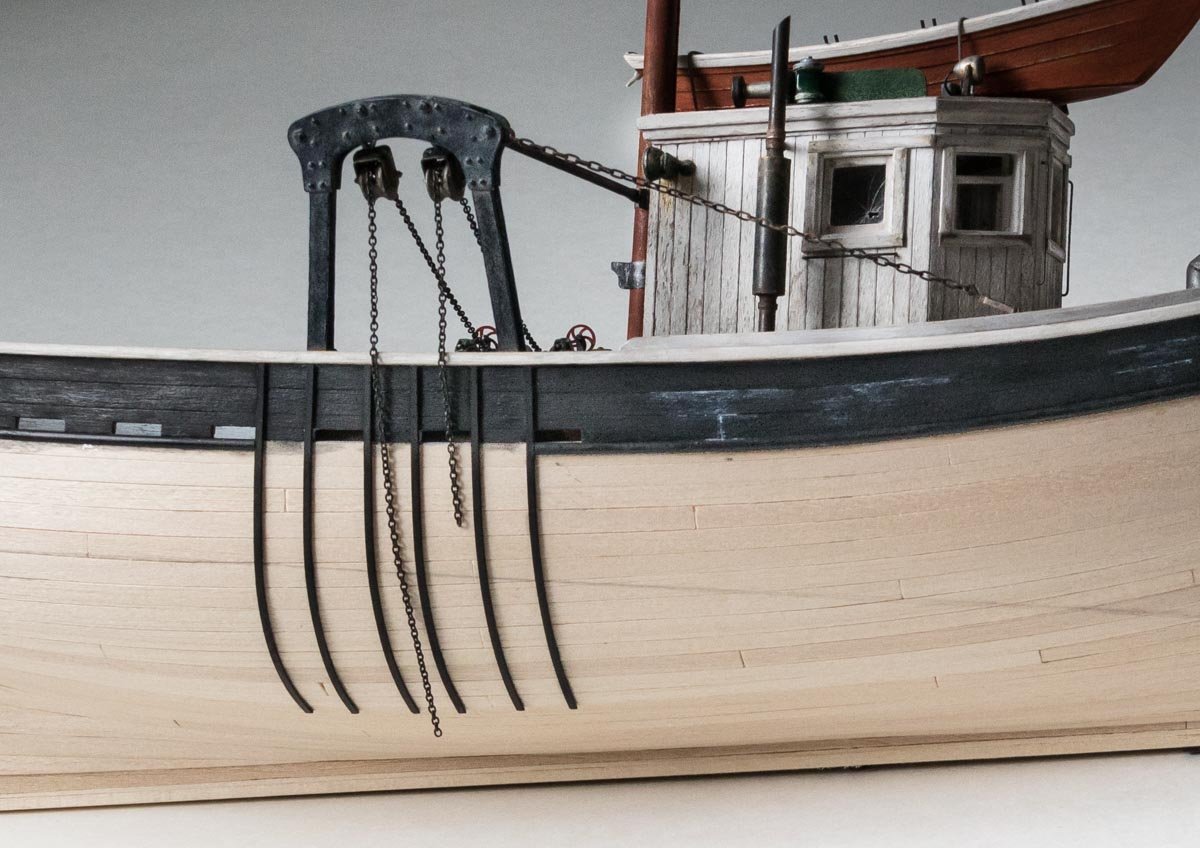
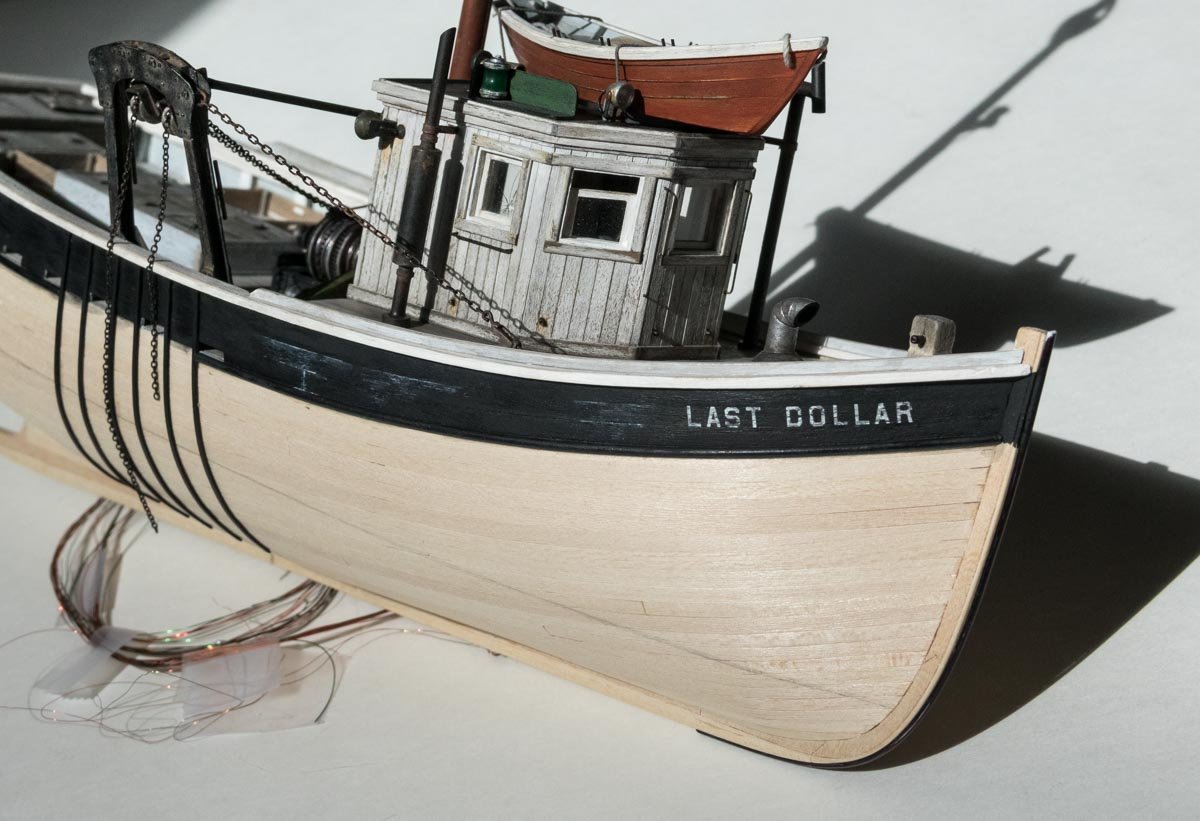
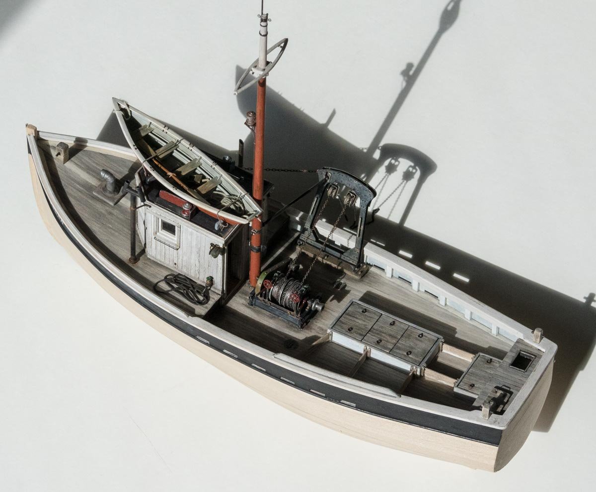
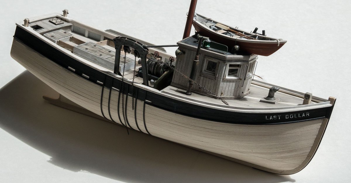
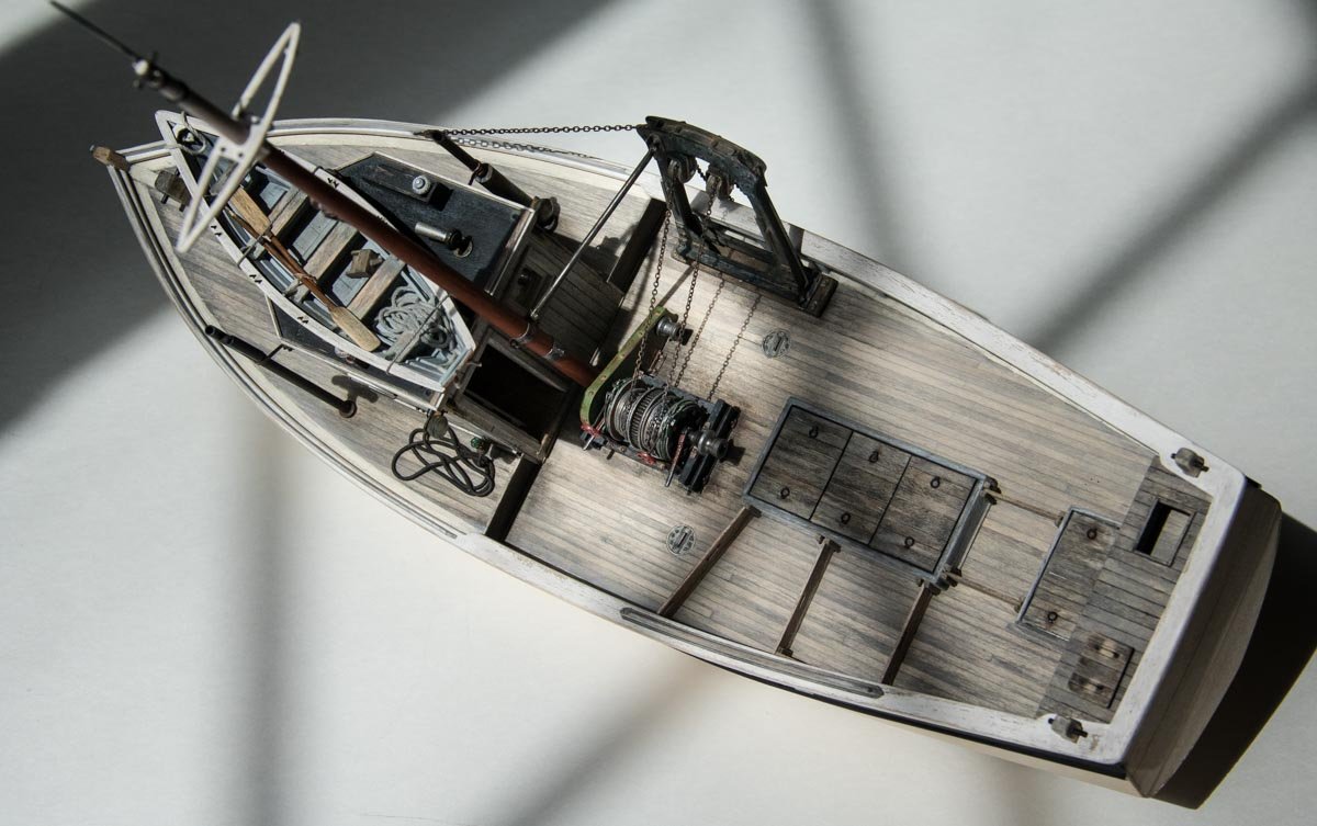
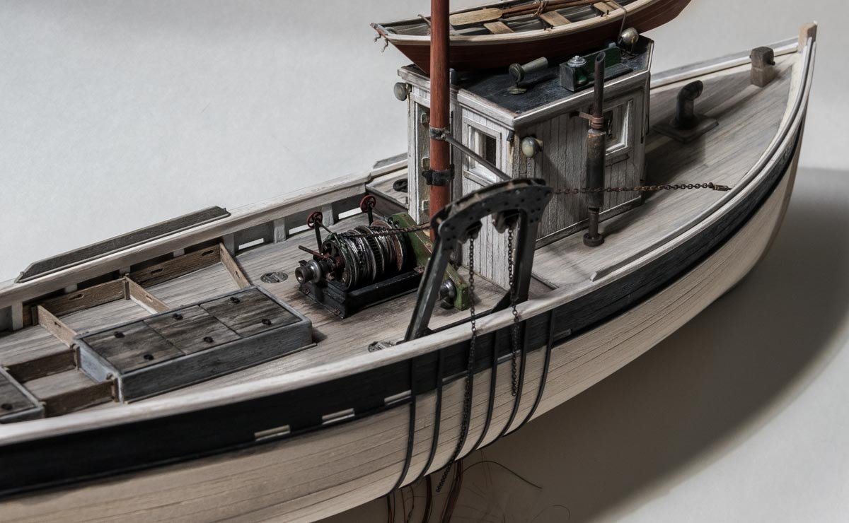
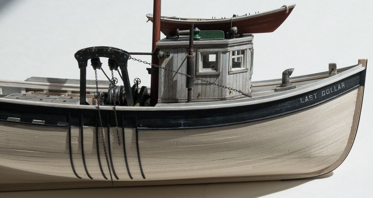
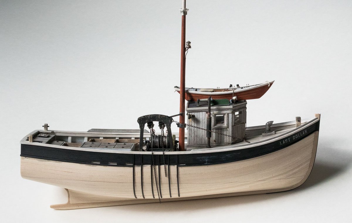
Thank you Keith for your wise-guy remark and Bedford for your comment. And thanks to all for the likes and to those following along quietly. Mounting the winch and some other stuff Here’s a small up date on the dragger. Before placing the winch onto the deck, I needed to wrap some additional outer layer cable onto the drums and a wrap or two of chain that will terminate at the otter boards (doors). I had pre-wrapped the drums with cable (beading wire) when I made the winch, so I only need a few wraps of this outer cable to finish it off. These last few wraps are a little rougher looking than the shiny beading wire underneath. This outer cable is actually stainless fishing leader wire and if I had to make the winch over again, I would use only this fishing wire and no beading wire at all. In fact, now that I have “discovered" this fishing wire (some of which was sitting in my tackle box all along), I don’t see myself using beading wire often, if ever again. I have used 7-strand beading wire simple because it looks like scale wire rope. But fishing leader wire looks even more convincing. And it is available in small sizes as well. For example, 10lb 7-strand uncoated is .008". The image below shows a comparison between .019" coated 7-strand beading wire and 40 lb test (.015") 7-strand uncoated leader wire. Notice how the twist is much tighter on the leader wire. Here I painted the leader wire black then sanded the surface with 1500 grit, which leaves color deep in the twists and accentuates the cable look. Most beading wire is nylon coated and little can be done to improve the look. The fishing leader wire looks great annealed as well. The winch is glued to the deck and the chains slung over the towing blocks. Color is added to the deck around the winch and gallows. In the image below, the iron straps that prevent the doors from slamming against the hull have been glued on. They will eventually get fastener heads and weathering once the hull has been painted. A half round styrene rub rail has been glued on and two different black acrylic paints were applied to the planks above it. The base coat is flat with semi-gloss dry brushed on here and there for a slight sheen. This breaks up the monotone look of the solid flat black. In this photo, the effect is noticeable on the left due to the angle of light and is difficult to see otherwise. I also added some salt leaching between planks caused by water seepage off the forward deck. And the boat gets a name. The dry transfer lettering is from Clover House in California and is applied one character at a time. Flat black acrylic is dry-brushed over the top. A half round iron stem guard has been added. The doors won’t be hung off the ends of the chains until the hull is complete. Thanks for taking a look. Stay safe. Gary
- 424 replies
-
- 37
-
-
Just catching up on your build Jean-Paul and it is looking amazing! Wonderful craftsmanship and meticulous work process. I especially like your personalized transom painting, very nice indeed. You’re creating a beautiful model! Gary
-
Just found this build log Jim and I've enjoyed reading through your progress so far. I really like small working/pleasure craft and this Chapelle Sharpie is a beauty. The fact that you're building her much the same way the full sized boat would be adds to the interest. Most of us love reading about this stuff. I've never know a modeler who has made a perfect model or wouldn't do things differently next time - the journey of improvement is part of the fun. Very nice work and looking forward to future posts. Gary
-
This model is coming along very nicely Kevin. It is a very interesting vessel and I always enjoy seeing builds of subjects that are out of the ordinary. Your clear explanation of the building process is much appreciated - and of course the videos are great. Gary
-
I dislike working with chain as it can be so fiddly. Just when you think you've got the end landed, it slips from your grip and the length of it collapses into a tiny pile - followed by the muttering of coarse language. Your forward stack turned out great, with all chains taut and nicely symmetrical side to side. I also like the companionways, such tiny work nicely executed. Great progress Keith - she's looking terrific! Gary
-
Beautifully done G.L. - congratulations on it's completion! Thanks for all the effort you put into your log to show us how you built her. Gary
-
Very nice work on the masts Greg. Beautiful clean wood cuts with nice sharp edges - and everything fits together just so. Sweet. Gary
-
Nice progress on your diorama Kevin - it's looking good! I like the way your stone work is turning out. Sometimes things just happen that way and one can never be sure what will look best. The next time, it won't be an accident - it will be experience. Keep it coming. Gary
-
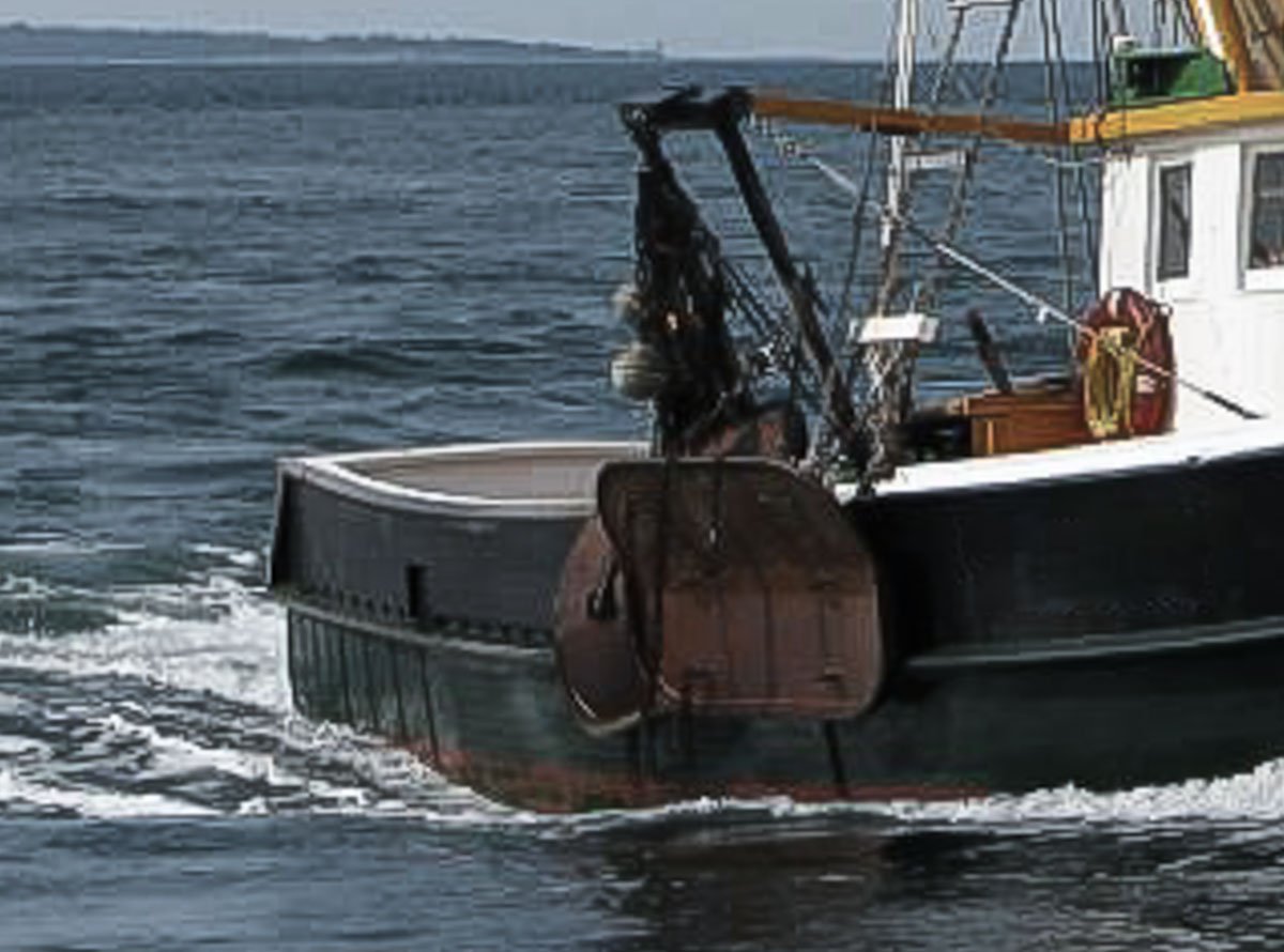
Thanks to everyone for looking in and for the likes. I just needed a short break and now it feels good to be working on the model again. I’m glad you found the short history of interest. I enjoy researching the when and why of whatever I'm modeling. For me, the story brings the object to life, whether it’s a model or an old woodworking tool that belonged to my grandfather. Thanks for the comment Chris and your continuing interest. Thank you John. I have been avoiding grocery shopping also - around 2week intervals, so maybe my mention of baked haddock was a sub-conscious thing. When all this is behind, I’m going to go out and eat and drink like a Roman emperor. Thanks for the kind words Keith and for stopping by. As Paul said – Japanese breadcrumbs. They provide a nice crispiness, and are great on oven baked chicken. I gave this a try and it works quite well. I did find that I had to set the line weight a little heavier for a decent transfer, but quite successful otherwise. I have some laser transparency film in the closet that I'll have to dig out and see if that works also, because I do like to be able to register the image onto the material. Thanks for the tip and the comment Wefalck. Thanks for stopping by Eamonn and for the nice complement. I hope you can find something useful here. Hello Jim – they are going to dangle off the gallows similar to this more recent boat. The model will probably end up on a simple diorama with a worker scraping or painting the hull. Not quite sure yet. Thanks for dropping by and the kind words. Gary
- 424 replies
-
- 12
-