HOLIDAY DONATION DRIVE - SUPPORT MSW - DO YOUR PART TO KEEP THIS GREAT FORUM GOING! (Only 51 donations so far out of 49,000 members - C'mon guys!)
×


FriedClams
-
Posts
1,368 -
Joined
-
Last visited
Content Type
Profiles
Forums
Gallery
Events
Everything posted by FriedClams
-
 Just came across your log Michael and I wanted to state, as others have, how fantastic I find your work. You are a true craftsman and artist - from the sculpted figures to your precise engineering and machine work. Wonderful work (like all your work). Thanks for showing us the process. Oh - and a great garden railway also. Gary
 -
Thanks for the information Clare. These cutters look like they open up some interesting modeling opportunities and I like how you're using yours. All those little accents, the diamonds and rectangles would be a bear to produce manually and uniformly. Maybe I'll take a look at the Cricket Maker. Agree totally. That is strange - sort of makes me suspicious. Keep up the great work and thanks again. Gary
-
Beautiful work you’re doing here Clare. Such an exotic looking vessel to my Western eyes. That is an interesting cutter. I was wondering what the thickness of the vinyl is minus the transfer material. I’m assuming it accepts sheet goods and not materials off rolls. If so, do you feel it would be able to cut .010” or maybe .020” styrene sheet? A very interesting and educational log. I look forward to future updates. Gary
-
Thanks for the information on this supplier Wefalck, Sounds interesting and I'm going to check them out. Hello Roger I apprenticed as an electrician in the early 1970s and took the Journeyman’s exam in 1975. One of the questions on the exam went something like “what are the acceptable raceways for use on commercial marine vessels". I answered GRC (galvanized rigid conduit). I passed the exam but got that question wrong. The issue as I recall is the possibility of free conductors slapping around inside a metal pipe on a pitching and rolling ship. Insulation is very vulnerable to chaffing wherever movement or vibration occurs and especially at points where the orientation changes from vertical to horizontal - at bends in the conduit, fittings, elbows, etc. This situation could easily cause systems failure or worse – fire. Corrosion is also a problem. I have been away from electrical construction work for decades and I have never been involved in any marine wiring, so I don’t know the codes or wiring systems that were or are being used. But considering the vital nature of modern electrical/electronic systems on today’s ships, I’m sure the electrical systems are rock solid and nothing is flopping around. Thanks for checking out my log. Thanks Keith. Gary
-
Thank you Keith and Druxey for your kind comments. Ands thanks to all for stopping in. Sorry John, I'm not licensed in Australia. Thanks for looking in. Hello Mark Thanks for the comment and the idea of using the tubing itself as a return conductor. That's a good idea, but as Wefalck stated, soldering copper onto stainless steel would be a challenge, especially keeping in mind the size of this material. By using these very fine wires I am able to run up to six wires through the tubing, so I'm not limiting myself in what I can do. In most cases there is a work around and the tubing isn’t needed at all. For instance, here I could have built a mast with a hollow down the middle, ran the wiring up the center and into the back of the light fixture, and a brass wire could simulate the conduit. But that is more time consuming than soldering on the fine wires so it wouldn’t have saved me anything. The desire to use this small tubing is a result of situations where there is no work around and I can’t conceal the wiring. Pendant lighting hanging from above, a gooseneck style light over a doorway, or sign illumination on the exterior of buildings are a few examples of what I mean. Mostly non-boat/ship modeling, but once the soldering technique was worked out, the work around became unnecessary. Thanks again Mark Hello Wefalck Brass in these sizes would be nice to have available and one could blacken them easily. I'll have to do a net search following the chromatography path! Thanks Wefalck. Gary
-
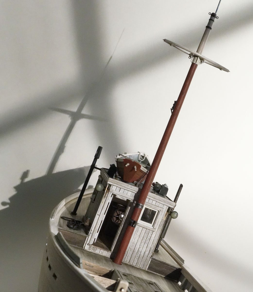
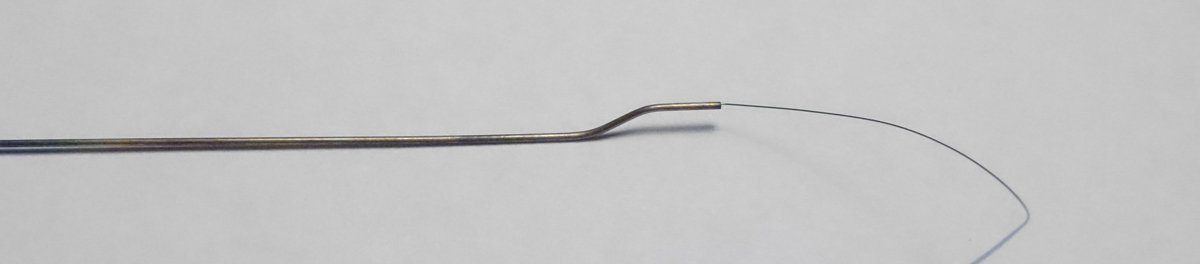
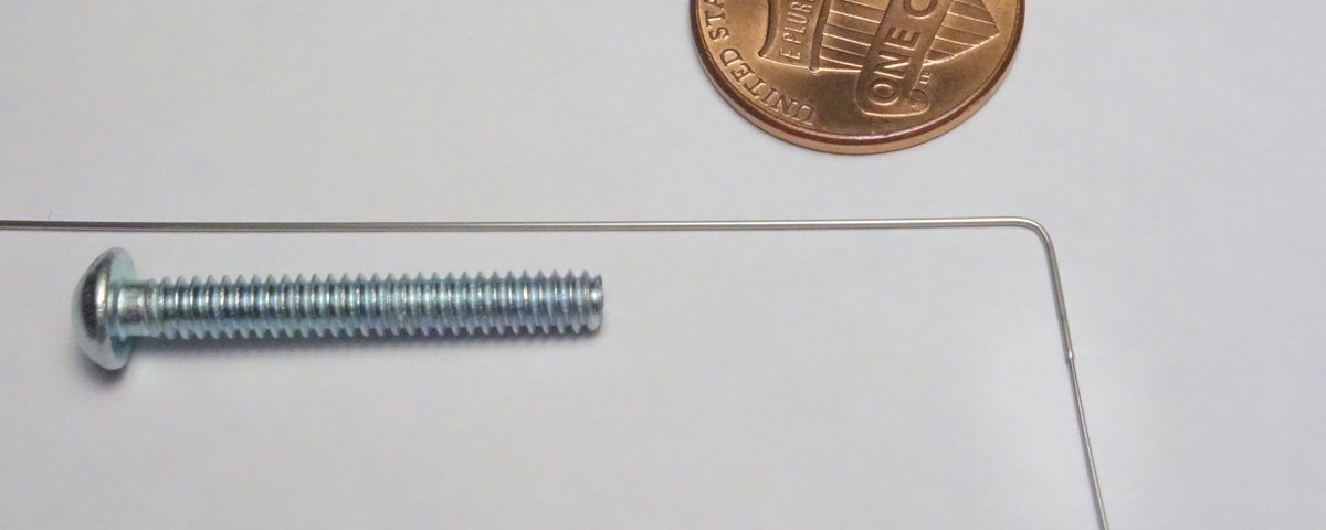
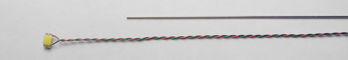
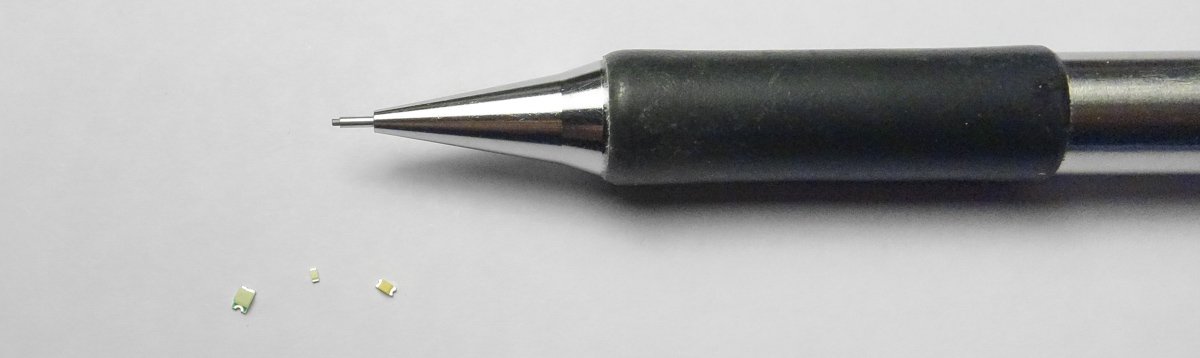
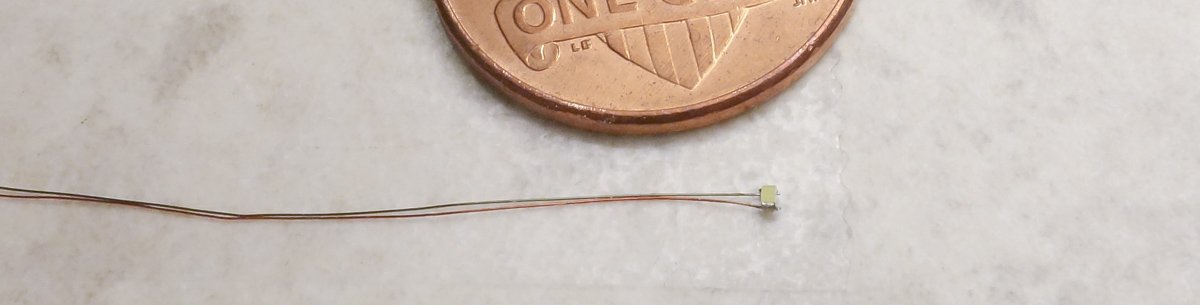
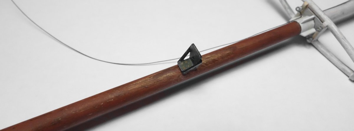
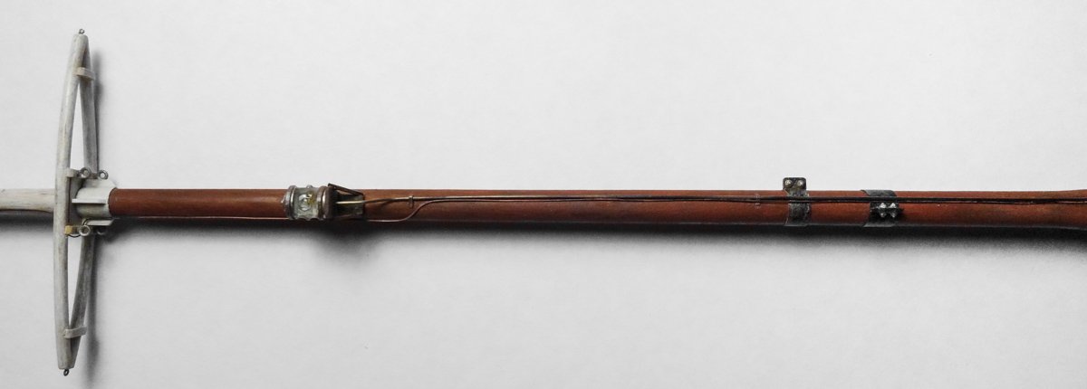
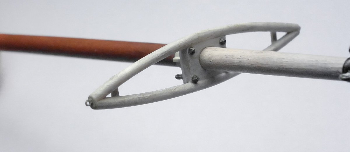
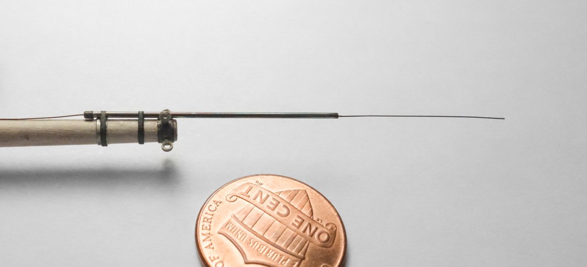
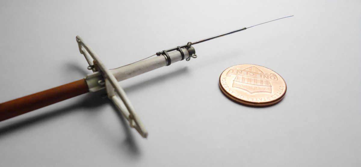
Thank you Druxey, John, Keith, Chris, Jim, Michael and Tom for your fine comments and continuing support. I appreciate it. And thanks to all for stopping in to take a look and hitting the thumbs up. More Mast Stuff Time to make up the mast navigation light and then place the mast on the boat. The NAV light will be functional and the wires for the LEDs will be run through stainless tubing up the front of the mast. Half-inch trade size electrical conduit has an outside diameter of .84”. In 1:48 that is .0175”, and it just so happens that I have tubing with an OD of .018”. Running conduit for wiring in marine applications even back in the 1920s was probably a code violation and required something like mineral insulated cable. MI cable is round but somewhat smaller in diameter than conduit, so this tubing will pass for either, and I don’t know where to obtain tubing smaller than this anyway. This stainless tubing is seriously small. It has a .002” wall thickness with a .013" ID. There is no visible seam and it is straight and smooth inside and out. As I understand it, this tubing is manufactured for instrumentation and medical equipment and it comes in a variety of sizes. Because the NAV light sits out from the mast, I need to bend an offset into the tubing. The wire sticking out the tubing is just a #34 magnet wire that I’ll use for pulling through the LED wiring. The process of bending the tubing is simple. A stainless wire that nearly fills the inside cross sectional area is inserted into the tubing and this keeps the sidewall from collapsing during bending. The radius is obtained by wrapping it around an appropriately sized machine screw being careful to keep the tubing pressed tightly into the threads. The thread walls act as a bending shoe and helps keep the tubing from blowing outwards. The example bend below shows the stainless wire inserted and how much spring back can be expected in a simple 90-degree bend. The insertion wire was pushed in just far enough to clear the bend. Had I simply pushed the wire all the way in and out the other end of the tube, I probably wouldn't have been able to pull it back out. Here is the problem with using small tubing like this for running LED wires. The wires on pre-wired LEDs aren’t fine enough to fit through the scale pipe. Even the smallest LED with the finest wiring I have been able to find won’t fit through. It may look close in the image below, but it isn't. Even with the wires untwisted and straightened – no. And in some modeling situations, you may want to run more than a single pair of wires through the tubing. So I solder my own surface mount LEDs with very fine wire, which also provides me with the luxury of deciding how long I want the leads to be without having to solder on wire extensions. When first confronted with the task of actually soldering wires on to these tiny things, it seems utterly impossible, even ridiculous. But once I got my technique down, I found it surprisingly simple and that I could succeed almost every try - even with the smallest diodes. And the LEDs are literally one or two cents apiece when bought off the reel, so tossing away a few mistakes is painless. I'd be happy to show the process on soldering these if there is any interest. Below are the most common sizes I use. For this NAV beacon, I’m using the 0603 – the mid size one on the right. The wire used is #39 gauge magnet wire. Including film insulation the OD is .0039”. The LED is placed into the light fixture and filled with clear Gallery Glass. I previously made the light fixture when I made up the wheelhouse NAV lights - that process it is shown on page 3, post #86. The bracket to hold the NAV beacon is made up from styrene, painted and attached to the mast. The tubing is glued onto the mast and a couple of foil “pipe clamps” are added. The light wires are pulled into the tubing and the beacon is glued on to the bracket. The wire from the radio antenna is routed down along side the tubing. Some pigment power is used to repair and touch-up scuffed areas. A quick check to make sure the thing still lights before the mast is set. I am going to hold off on the boom, mast cleats and the mast coat until after the gallows and winch are made up and placed. Next comes the gallows frame. Thanks for stopping in to take a look. Gary


- 424 replies
-
- 31
-

-
Hello Keith. Just found this log and have enjoyed reading through it. This is an interesting subject and the model is coming along very nicely indeed. I like the cannons (wheels too), and the control pedestal is crazy detailed at such a small size. I also like the color of the deck and the overall feel of the model. Your decision to redo the masts I believe was a good one and the replacements look great and to scale. I couldn’t agree with your philosophy more Keith - perfectly stated, and that is how I approach my own models. It’s like we’re brothers from different mothers. Looking forward to future updates. Gary
-
This is so sad to see happen. I've pulled up a front row seat for this build log G.L. A great idea and I know I will learn a lot from it. Gary
-
Excellent work on these small brass details G.L. I find small open boats so appealing and your model here is very nicely done - every detail. A pleasure to watch it come together. Gary
-
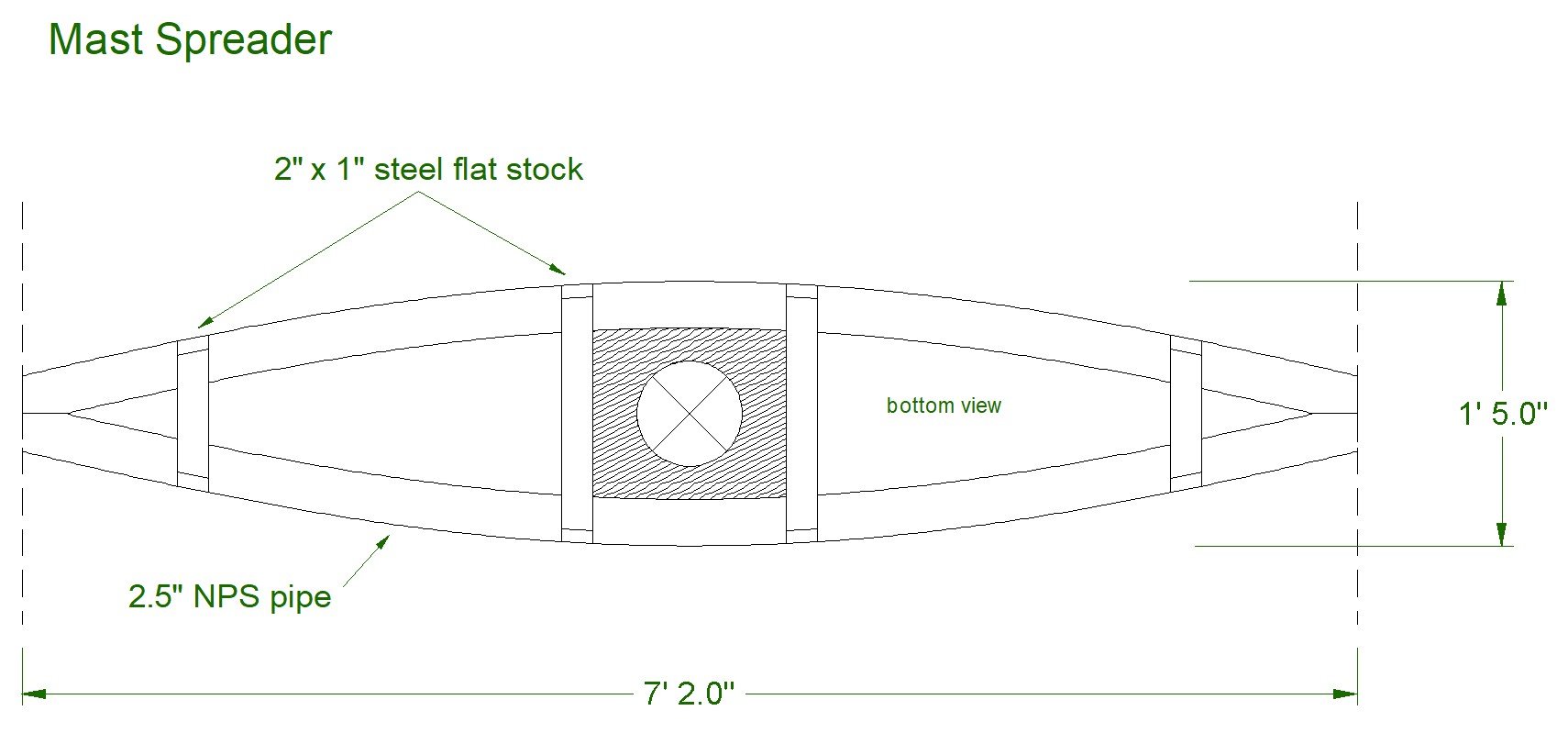
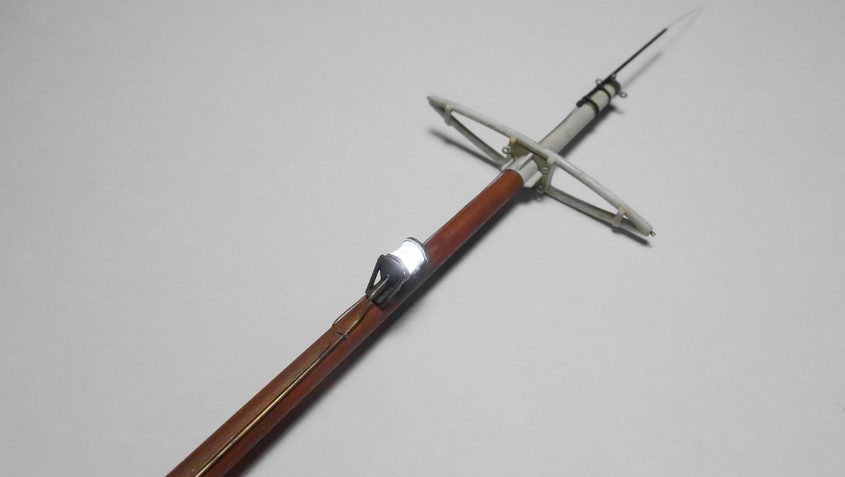
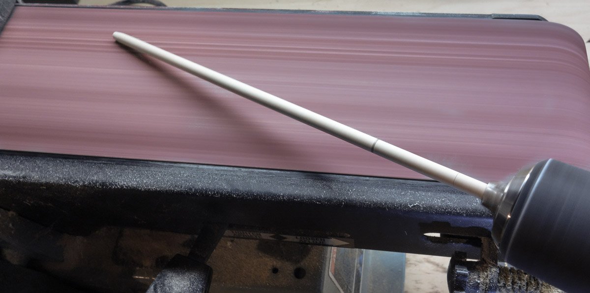
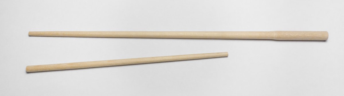
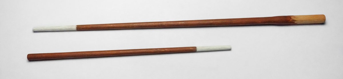
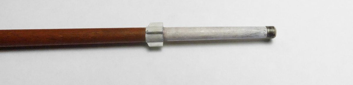
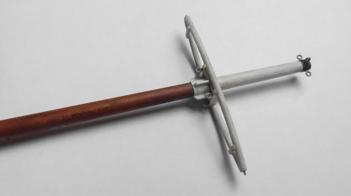
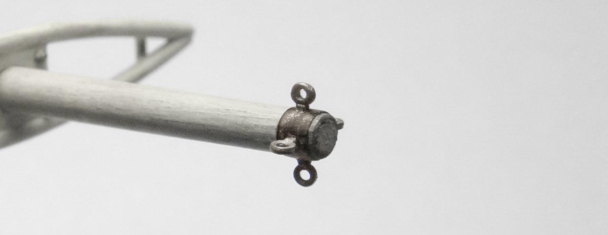
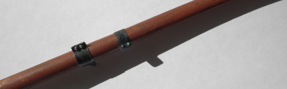
Thanks to all for looking in and for the likes. Hello Druxey. Yes I'll keep that in mind, but does your household qualify as a non-profit organization? Hey Tom. That's a very cool and helpful site. Thanks for the link. Some mast stuff I want to begin building the gallows frame, but because it has a supporting brace that attaches to the mast, I need to make up the mast and get it placed first. But I won’t be stringing any stays or shrouds just yet. The mast on this boat is 25.5’, which is slightly over 6.25” in 1:48. The boom is 21’. I mark and cut these two pieces from 1/4" dowel. I used the brute-force method of a spinning dowel against a moving sanding belt to gain the taper required. You can reduce a ¼” dowel down to a toothpick in about 30 seconds with this approach - just be sure the dowel is spinning in opposition to the travel of the belt. As the pieces are being sanded to shape, I repeatedly check the diameter of the tapers at several points along their length with calipers. Once I get close to the proper taper, I spin the dowel into incrementally finer handheld sandpaper. Finally I have two pointy sticks. They were painted with acrylic paint. Many of these boats had bright orange or red masts. But many did not and were often painted either brown or black, which is good because I really didn’t want to paint it orange. I tried various values and mixtures of orange, but each time it made the boat look like a toy. So I ended up using burnt sienna and a little chalk for the lower mast and off white above the spreader. I drew up the spreader and printed it out to be used as an assembly template. It is made up entirely from styrene except for the center (hatched area), which is basswood. The four eyebolts receive the shrouds. The fore and aft stays will be connected to wire rope slings that wrap around the mast just above the spreader. The mast gets a collar with gussets to hold the spreader. The band at the top of the mast will be part of an eyebolt assembly. The spreader is slipped onto the gusset ring and glued down. Holes for the eyebolts are drilled through the band at the top of the mast and the eyebolts are glued in. The close-up below shows the top eyebolt assembly that will eventually receive stays/cables. The ring is made from wine bottle neck foil and the eyes are styrene. The top of the mast is under a 1/8” in diameter and this foil works great for these small applications - it lays down nicely, and the scale thickness is just right. Both the foil and eyes are dry brushed with Testors enamel “steel" and finished off with some pigment powder. The eyebolts and the nut/bolt/washers shown in this posting are injection-molded styrene from Grandt Line Products. The eyes (which are not their smallest) are .05” OD or 2.5” in 1:48. The N/B/Ws are simply beyond ridiculously small and come in many styles and sizes. I use these miniscule styrene bits guilt free and without reservation because I simply cannot make them myself. Down on the lower end of the mast are two bands that will be attachment points for the boom and gallows frame brace. The wider one on the left is for the boom and has a brass attachment tab facing aft to accept the boom. The tab is pointing down in this image and barely visible. Again, the bands are foil and nuts/bolts styrene. I’ve added a radio communications antenna to the model. It is undoubtedly too short to effectively transmit given the modulation technology of the era, but it functions as a sort of visual stand-in. Two-way radio antenna design is a deep dive into communication electronics and is subject to variables including transmitter power, frequency, travel distance and type of modulation. Modulation is key and refers to the method in which an RF signal (voice or data) modifies the characteristics of a steady state carrier wave. The carrier wave with the embedded information is what gets broadcast via the transmitter. Radiotelephone modulation in the 1920s was for all intents and purposes limited to AM double sideband w/full carrier (DSB-FC). This method is inefficient and requires considerable transmitter power and/or antenna. A much-improved and much less power hungry derivative of this type of modulation is single-sideband (SSB), but it wasn’t commonly available until the mid 1930s even though it was patented in 1915. I’m beginning to babble which is a sure sign that I need to end this post. So anyway, the aerial is made of magnet wire and stainless tubing and the strapping holding it to the mast is paper. Thanks for stopping by to take a look. Gary


- 424 replies
-
- 25
-
-
Terrific eyebolts Keith. I admire your heads down work ethic in producing these many duplicate parts. I’m sure it was mind numbing, but you pushed through it. Gary
-
Ouch! I have a thought for what it's worth. The hand wheel for what seems to be a friction brake on the dual purpose winch appears to be in spot where it would cover the deck repairs - if only the winch assembly was placed slightly to the rear of where they are on the actual boat, maybe a foot to 18". A paper cutout of the winch/hand wheel footprint could help decide if that would be an acceptable or unforgivable alteration. Gary
-
Beautiful work Dan - and such an ambitious project. Congratulations on its completion. Wonderful model and build log. Gary
- 238 replies
-
- 2
-
-
- leviathan
- troop ship
- (and 2 more)
-
Hello Wefalck, I've been reading your log from the beginning and have just caught up. A very interesting and educational thread to be sure. Your machine tools are great but it is your skill in using them that is so admirable. Astonishing detail at so small a scale. Very impressive and beautiful work! I look forward to future updates. But . . . . . are you sure that match stick isn't really a modified broom handle with a sponge stuck on the end? Gary
-
As Keith stated above - this model does look like the real thing. Nice meticulous work on the stringers and risers G.L. She is looking sweet. Gary
-
I completely agree with Marks’ statement above. An astonishing amount of miniature brass detail all nicely made and precisely duplicated. l really like the color and richness of the deck as well and the multiple top coats gave it a beautiful depth. Your work process is a pleasure follow. Very nice Keith. Gary
-
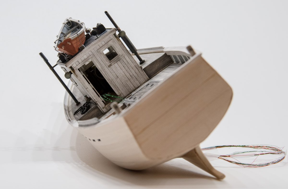
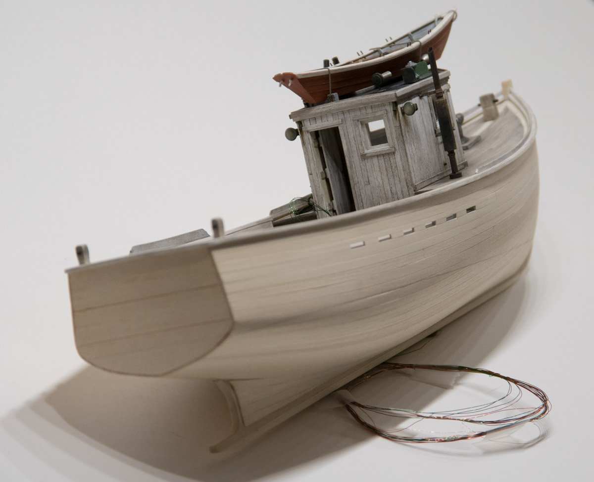
Hello G.L. Yes, the hull too will be weathered and worn to match the rest of the boat. I agree, at this point the hull does look rather clean and maybe even out of place, but that will change. My general approach to building a weathered model is to build it like I didn't intend to weather it and at the last moment changed my mind. In this case I try to imagine what the real boat must have looked like sliding off the ways for the first time - clean, tough and expertly made. Years of hard service, inconsistent upkeep and the relentlessness of Mother Nature change her appearance, but it is only cosmetic. Thanks for stopping by. Hello Tom and thanks. If in the end it turns out well, I will offer it free to one of the maritime museums here in New England if they want it. Gary
-
Thanks to all for stopping by and hitting the like button. Thank you so much John. Thank you Ekis for your nice comments. I’m pleased you’re inspired to perhaps give some these techniques a try for yourself, but be forewarned - weathering is addicting and the results can be unpredictable and often disappointing. Be sure to do test trials on scrap material first. Weathering can destroy a perfectly nice model in a heartbeat - no need to ask me how I know this. Thank you Hubert for your high appraisal of my work - I’m blushing like a newlywed. I’m glad you are following along and enjoying the log. I am absolutely terrible at tying knots and can never seem to remember what goes under where and over the top of which. I am lucky to get my shoes tied every morning - well most mornings anyway. Thanks for your comment Keith. As always Druxey, thank you for your comments. Gary
-
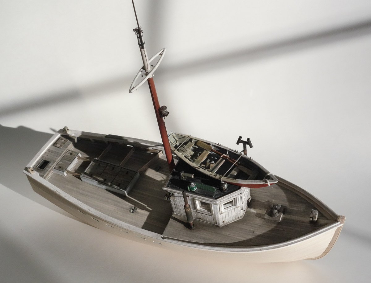
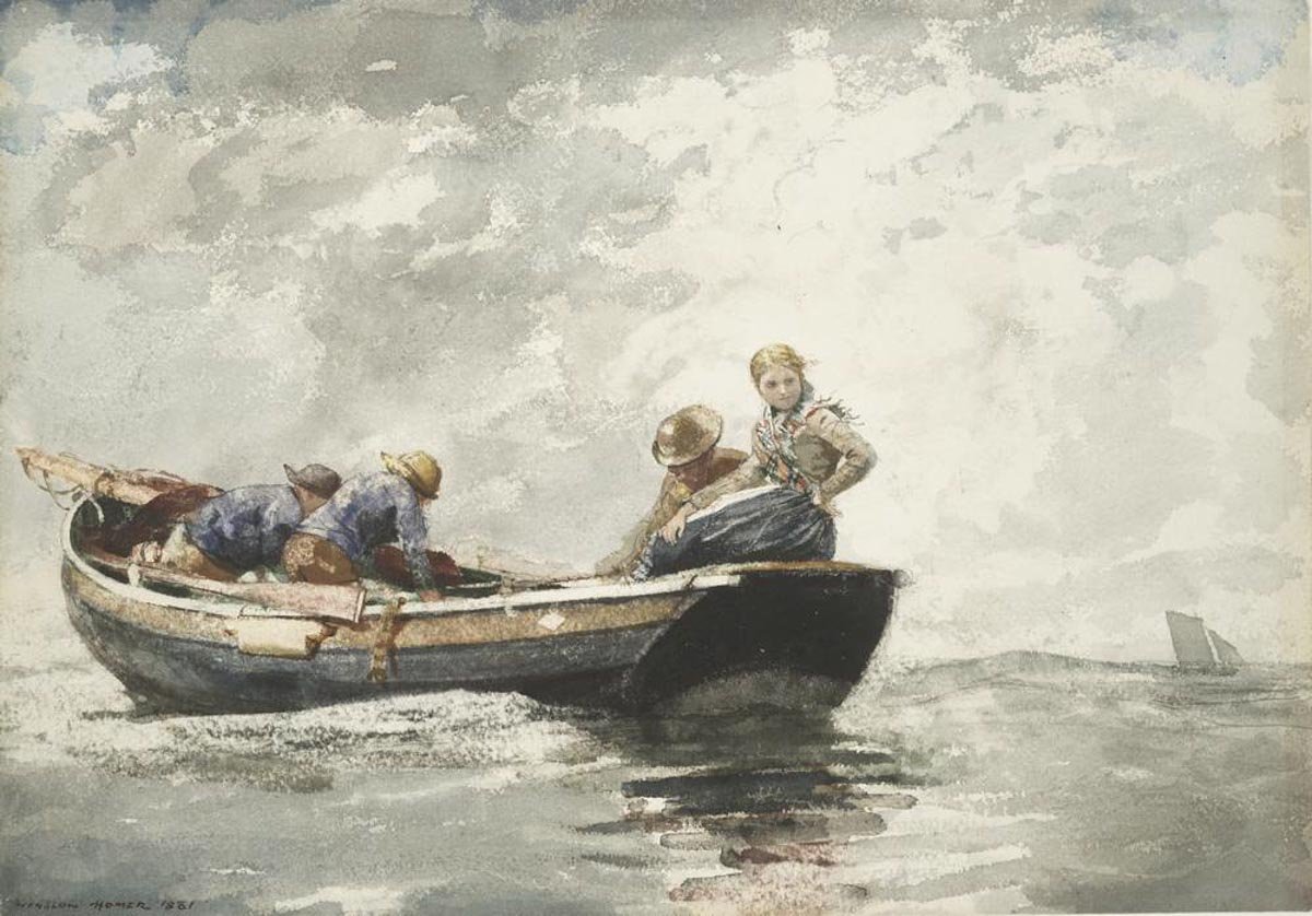
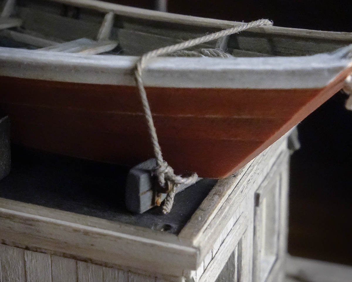
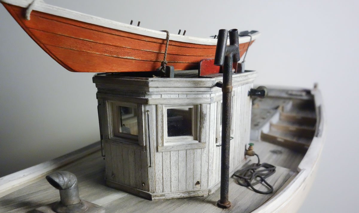
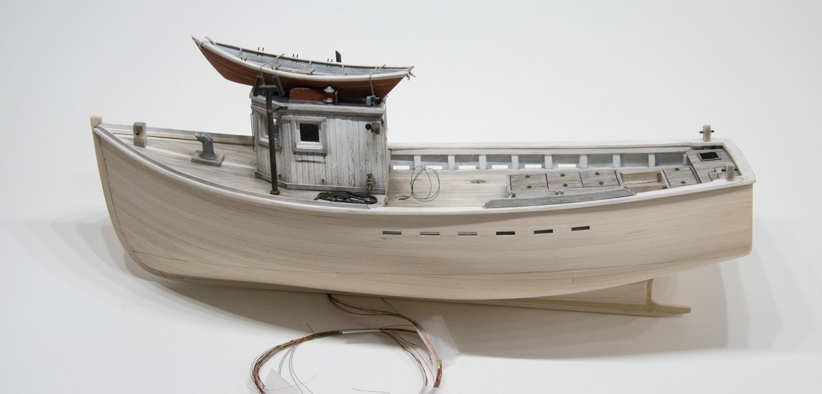
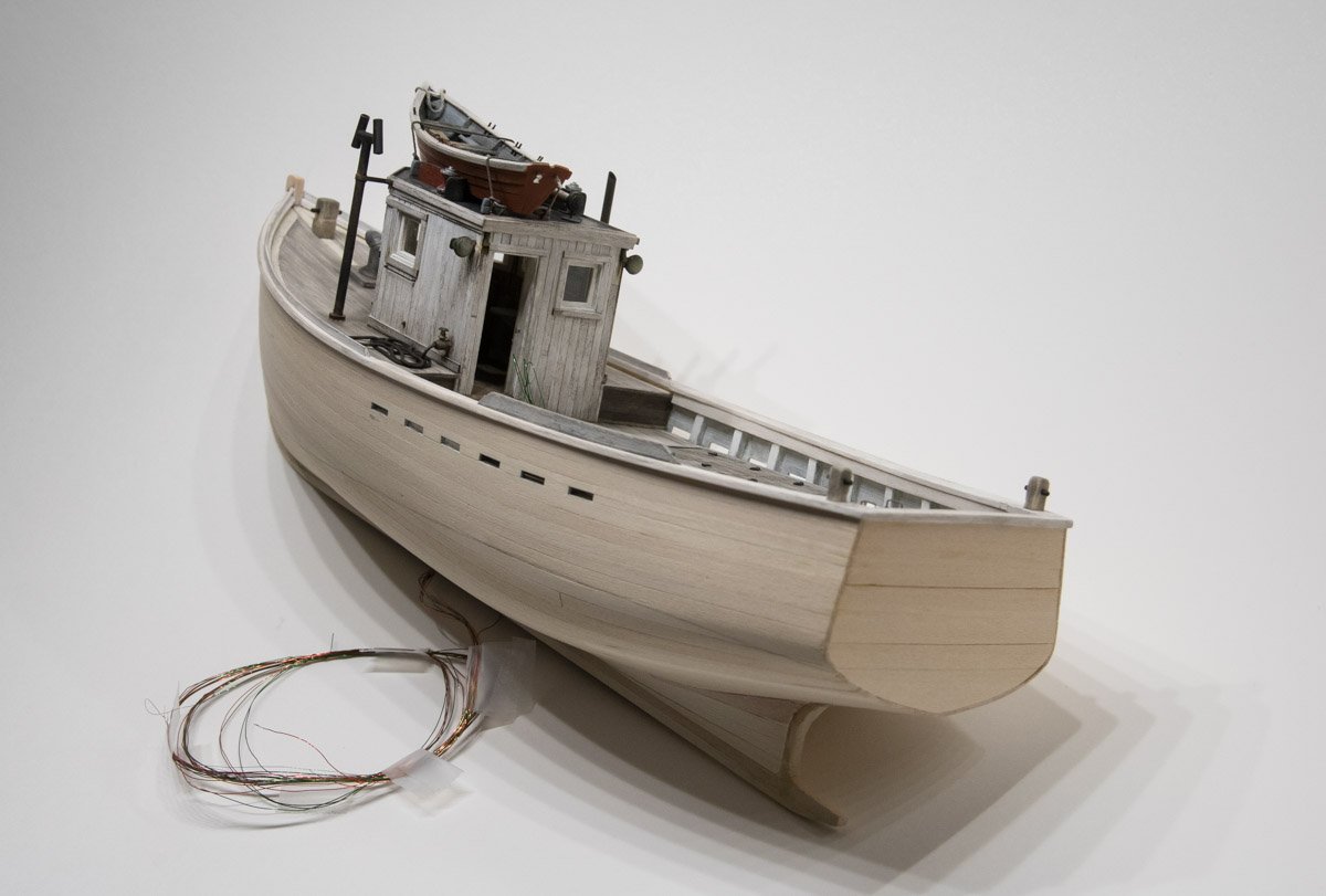
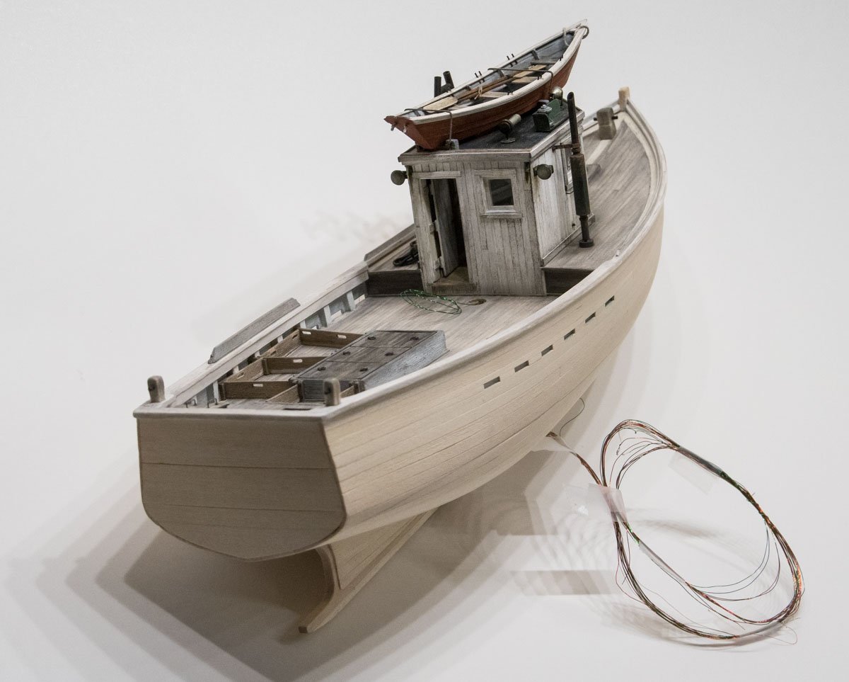
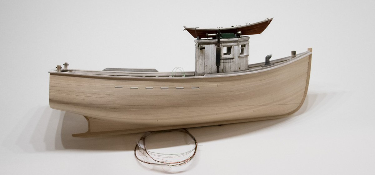
Thanks to all for stopping by and hitting the like button. Thanks Keith and John for your comments. Yes it’s a simple and fairly convincing technique for piles of tired looking rope. Hello Michael – thanks for the kind words. I’ve enjoyed doing the weathering on this model, but it does make for slow progress. So much trial and error involved - a lot of both. But I knew this before I started and the process is fun. And I'm in no hurry to finish. Thanks for swinging by and for your comments. Well I haven’t needed to use a microscope yet, but I do have the most powerful magnification lens snapped into my OptiVisors. Thanks for stopping in and for your nice comment Tom. I’m glad you found my build log Ken and I hope you find something useful here. Thanks for the nice comments. Hello Michael and Druxey. Yes, I have always admired Winslow Homers' work. He was quite prolific and a master at several art mediums. Here is another of my favorites by Homer from the same time period. Fisher Folk in a Dory - 1881 - Harvard Art Museums/ Fogg Museum So here is a short update on the dragger. The dory was mounted to the wheelhouse roof. It sits on wood frames and is tied down with rope attached to eyebolt rings. I tried to make the knot as small and unobtrusive as I could – I think it's called the “halfwits' hitch". Glue holds it together. I also added some vertical and horizontal grab irons to the pilothouse. It has occurred to me that most of the photos I’ve provided over the past few months have all been close-ups and small portions of things. So I took some overall shots of the model to show where it stands at this moment. The boat is 11 ¼” in length. Thanks for stopping by. Gary
- 424 replies
-
- 28
-
-
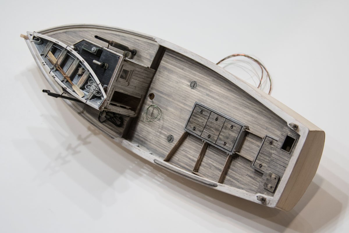
Hello Maury and Mark. I built a sardine carrier that also had these offset rings in the hatch covers and wondered about that myself. The hatch covers on my model were considerably larger at 2’ wide by 6.5’ long and would have required a man on each end to lift them, but were essentially the same configuration. I think this ring placement was to keep the cover from rolling over to vertical once it was lifted. This would almost certainly happen if the rings were placed in the center at each end unless the cover was perfectly balanced which is unlikely. And I believe that rings were used instead of regular door pull type handles because the rings drop flat onto the cover when not in use and wouldn’t be crushed or broken the first time something heavy landed on it. Or I could be totally wrong. Maury your model is looking great and your log is a pleasure to follow. Very nice work. Gary
-
I’ve been following along on your build and enjoying watching your progress Kevin. Very nice work you’re doing here and boy she is big model isn’t she! I really enjoy these working boats - especially fishing boats. Excellent job on that highly detailed winch. Looking forward to future updates. Gary
- 337 replies
-
- 4
-
-
- finished
- mountfleet models
- (and 1 more)
-
This is a beautiful model you’re building here Bedford. And who doesn’t love a lapstrake pulling boat? 1:8 is such an enjoyable scale to work in and your metal details are really great. Extremely nice work. Oh - and your full size build is stunning and I’m sure she’s a pleasure to sail and row. Gary
-
This is such an interesting craft Elroy and I like the fact that you’re providing detailed information on how they were/are built. Good luck on your build - I will follow along. Gary
-
This looks to be an interesting build Ken. I will follow along. Gary
- 238 replies
-
- 1
-
-
- sloop
- providence
- (and 1 more)