HOLIDAY DONATION DRIVE - SUPPORT MSW - DO YOUR PART TO KEEP THIS GREAT FORUM GOING! (Only 51 donations so far out of 49,000 members - C'mon guys!)
×


FriedClams
-
Posts
1,368 -
Joined
-
Last visited
Content Type
Profiles
Forums
Gallery
Events
Everything posted by FriedClams
-
 Just catching up Paul and I want to congratulate you on your fine model. It turned out excellent and in no way looks like a first build. It’s cleanly made and nicely fitted together. Good paint too. Gary
- 87 replies
-
- 4
-

-
- bluejacket shipcrafters
- red baron
- (and 3 more)
-
Just catching up Ekis and I see the superb work continues. Your village is coming along beautifully! Gary
-
Really nice work on those tracks Keith. I agree with Keith and Pat - no one will ever know the tracks are a hair wider than prototype. I certainly wouldn’t have known. I bet that was time consuming laying them down and getting the all those curves to sweep naturally. And they contrast nicely with the wood deck as well - great visual appeal. I like it! Gary
-
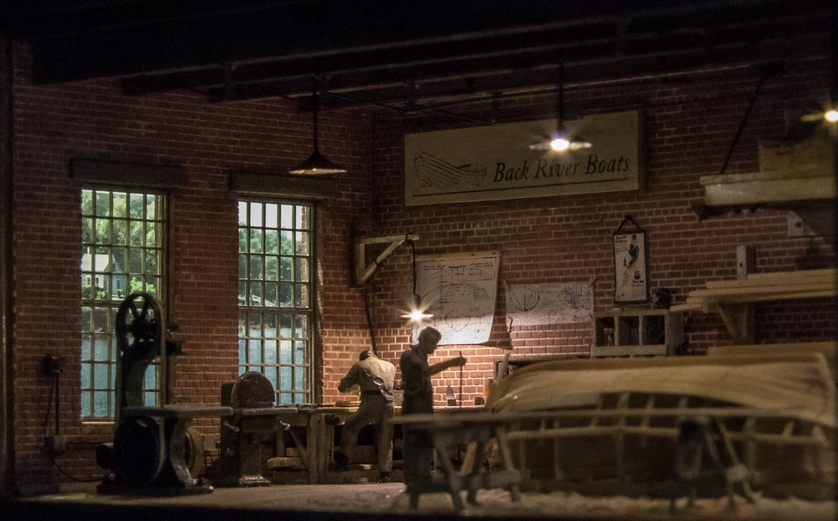
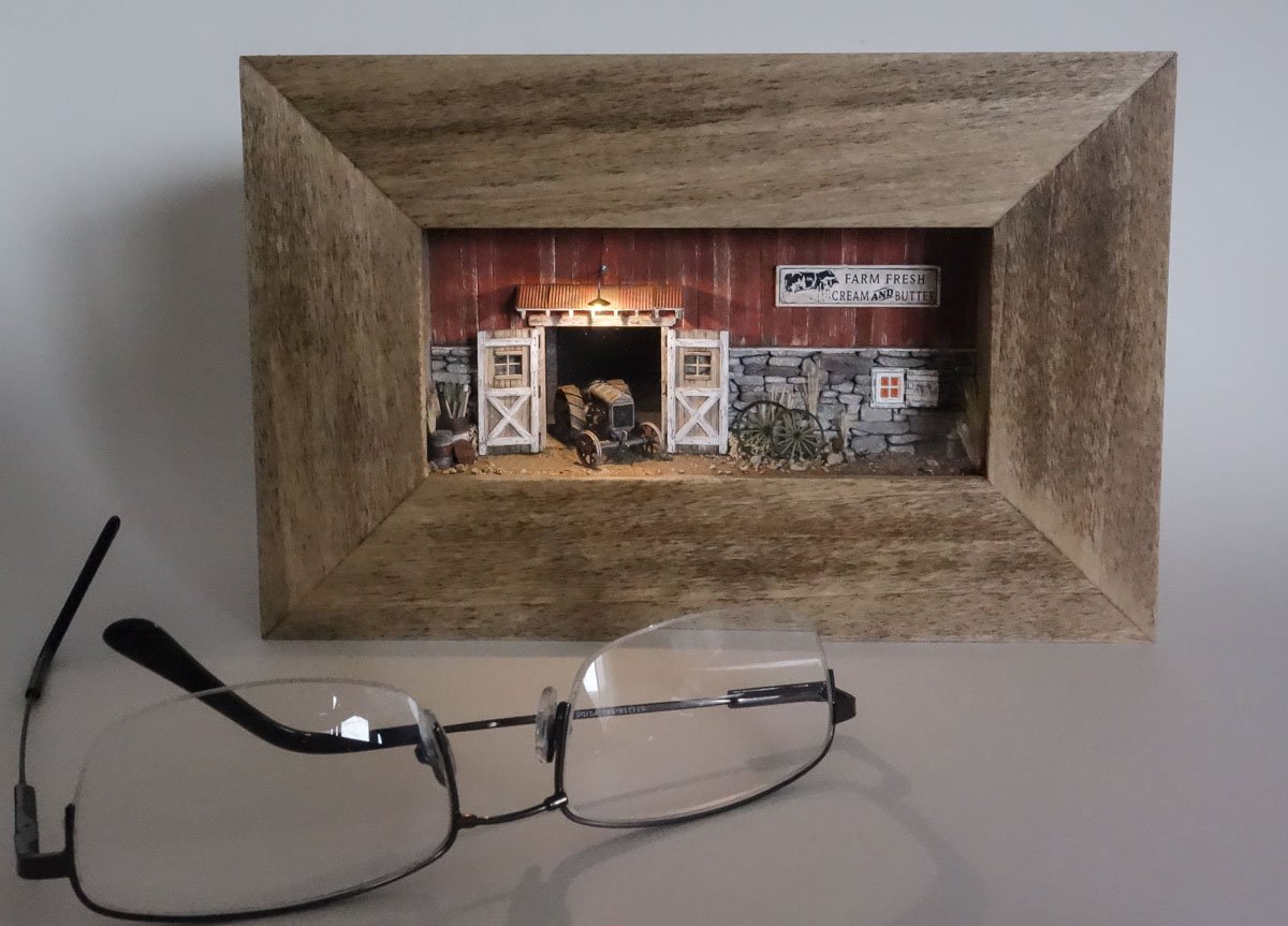
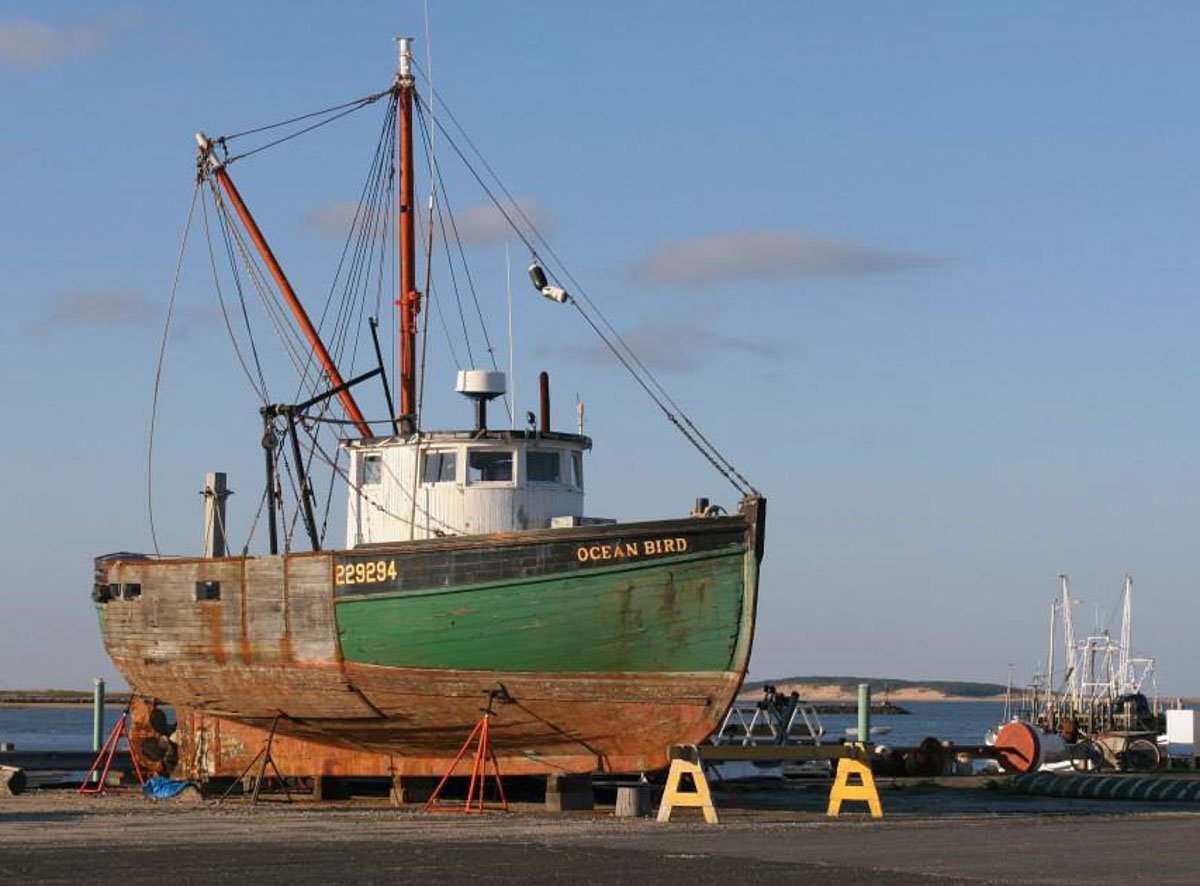
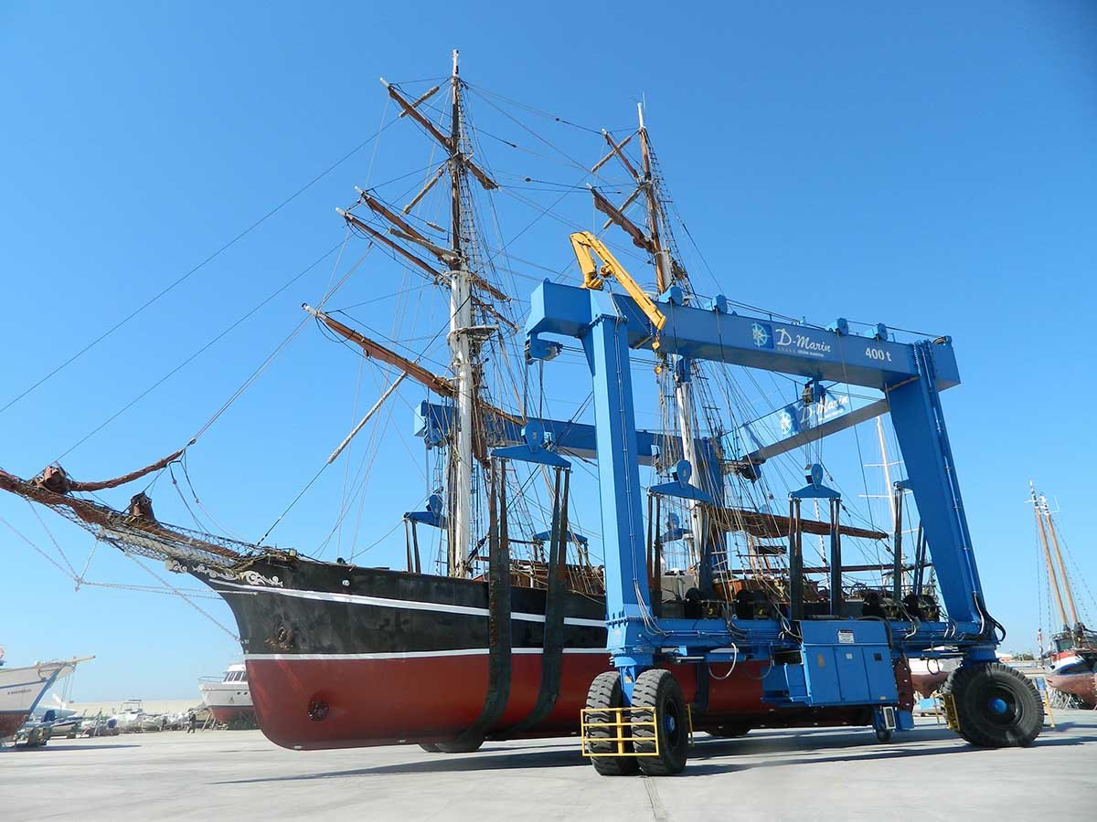
Thank you all so much for the wonderful comments. It is so great to share a hobby with like-minded folks. Hello Druxey and Allen. Thanks for asking and your interest. When I began this Stonington boat, I always had it in the back of my mind that this would be a trial run of sorts leading up to a larger and more complex Eastern-rig vessel. I always figure the scar tissue developed during one project will benefit me in the next, or at least help in avoiding a total face plant. There are numerous weaknesses and flat-out errors on every model I've ever made and that tradition will continue, but I hope to make new mistakes and not repeat ones made before. There are very few wooden hull Eastern-rig boats still floating today. They have mostly been replaced by steel hull stern trawlers, but in mid-century New England, they were ubiquitous. Based on my interests and being a mid-century New Englander myself, an Eastern-rig scallop dragger out of New Bedford seems a natural next project. I didn't have much in the way of plans for the Stonington boat and I spent ridiculous amounts of time scrounging around in search of tidbit information. I'm not going to do that on the next model, so I need to hunt down comprehensive plans and I know who has them. The research library at Mystic Seaport is a rich resource of plans for vessels of all types, but the vast majority of the material is undigitized and requires on-site research. Their archives contain the original drawings for dozens and dozens of Eastern-rig boats – but the library is closed to visitors due to Covid. When they re-open, I will travel down to Connecticut and see what they got. In the interim I'm going to work on some non-floating modeling and make another 1:87 mini- diorama. Early on in this log I posted photos of one of these small dioramas – a small boat building shop. That was the second in a series. The first was this old Fordson tractor emerging from a barn. Both dioramas are the same size. The third will be a 1920s auto repair shop and will keep me occupied until I can begin work on the scallop boat. Hello Wefalck. No, it's not in the tidal zone and your question is a good one. I looked at many photos like this and though “how did that boat get there”? What was confounding to me is that the boat stands, props and cribbing are in the way of whatever placed there. How do you hold the boat up and pull the transport out from under it at the same time? I then found this video and the “well, of course” moment happened. The video is from a manufacturer of boat stands and it demonstrates the ease of how it's done. The first 45 seconds or so is product sales pitch. Brownell Boat Stands Demonstration - YouTube And there is always plan “B”. Thanks again everyone. Stay safe. Gary
- 424 replies
-
- 20
-
-
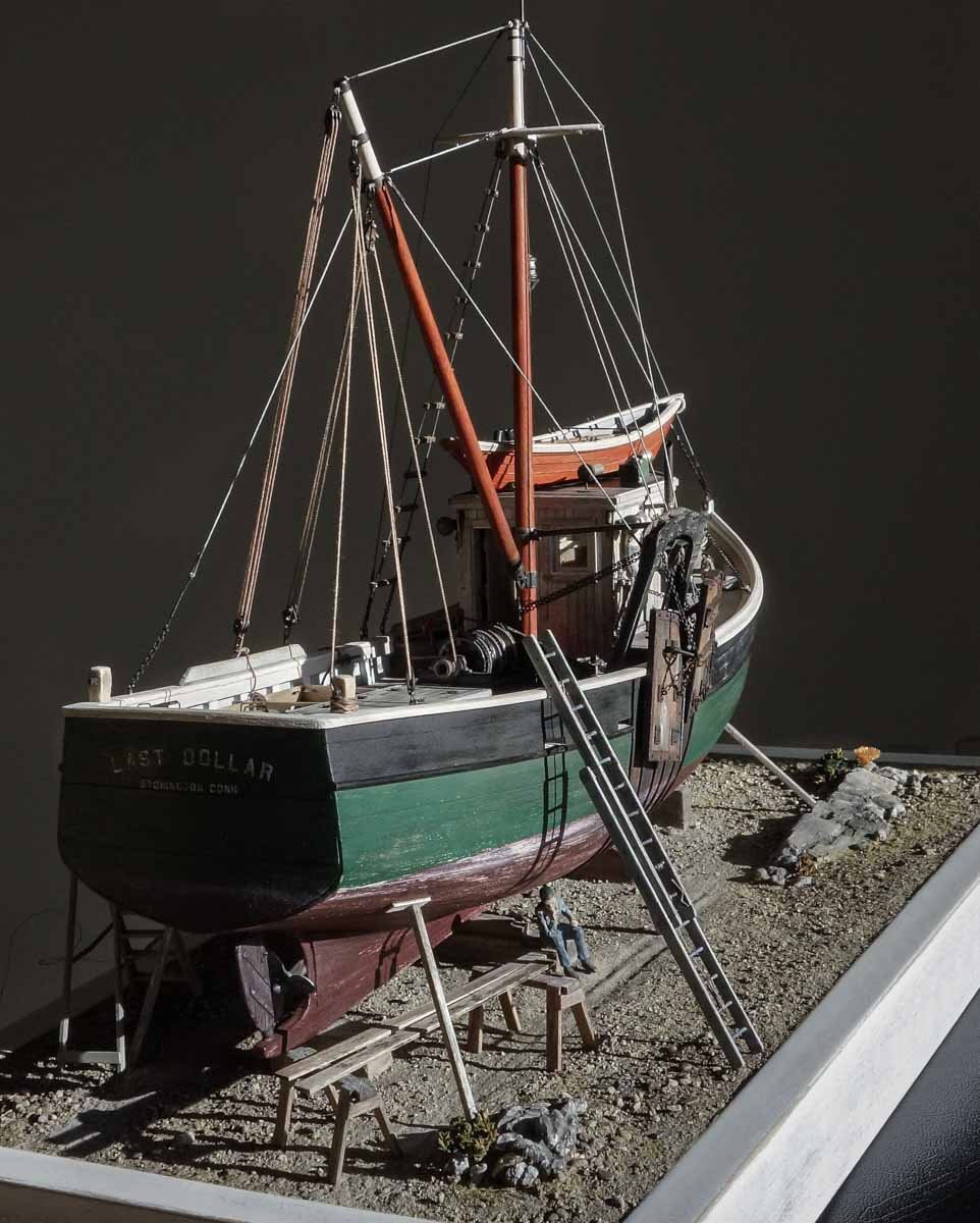
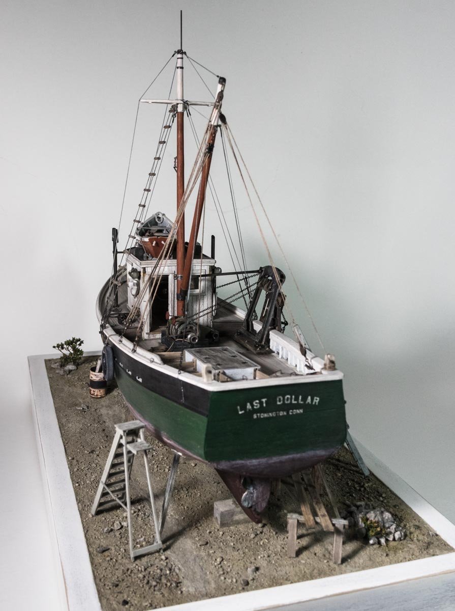
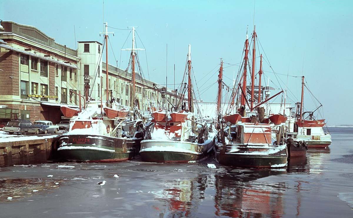
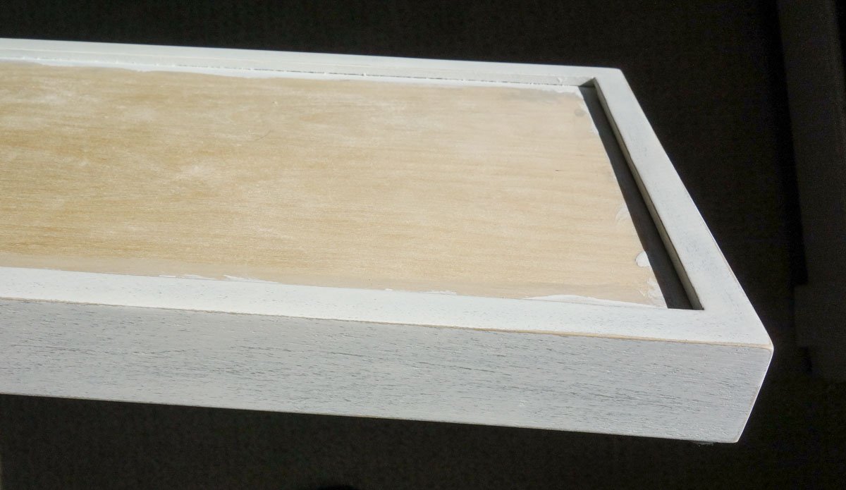
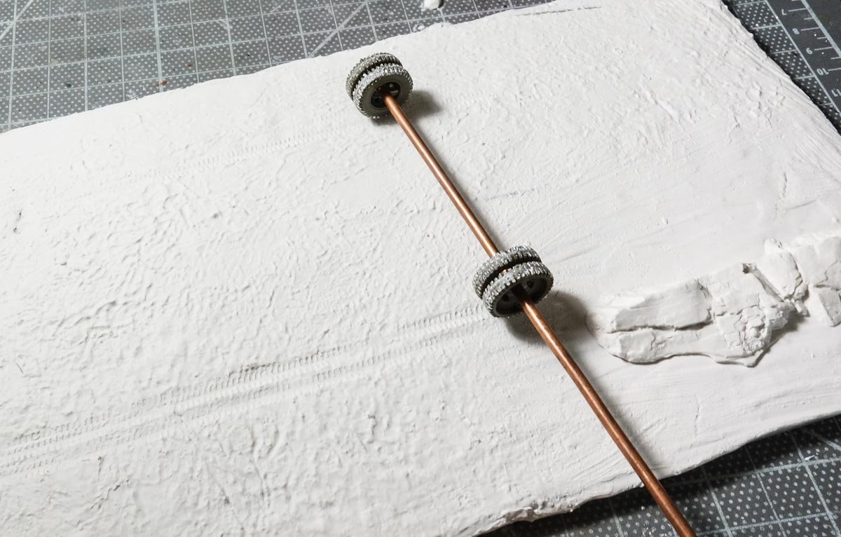
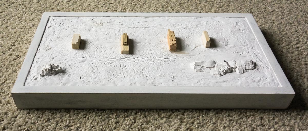
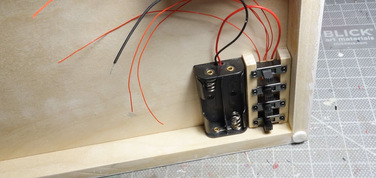
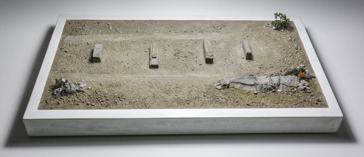
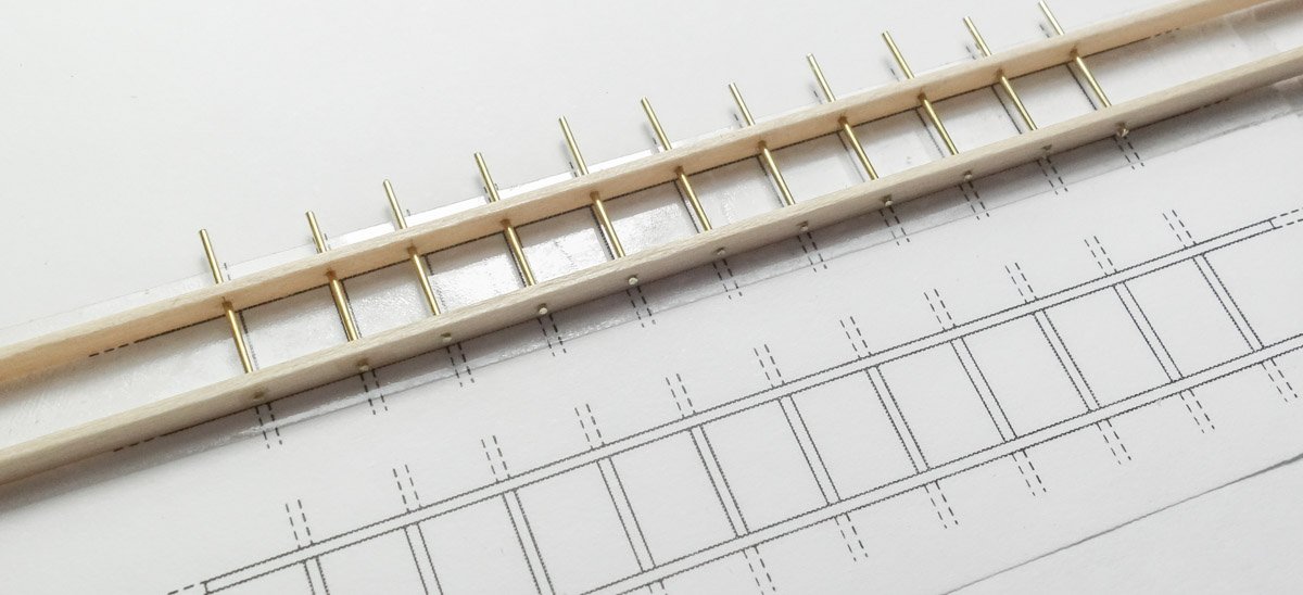
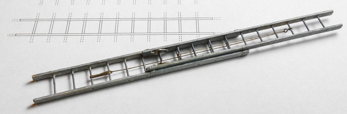
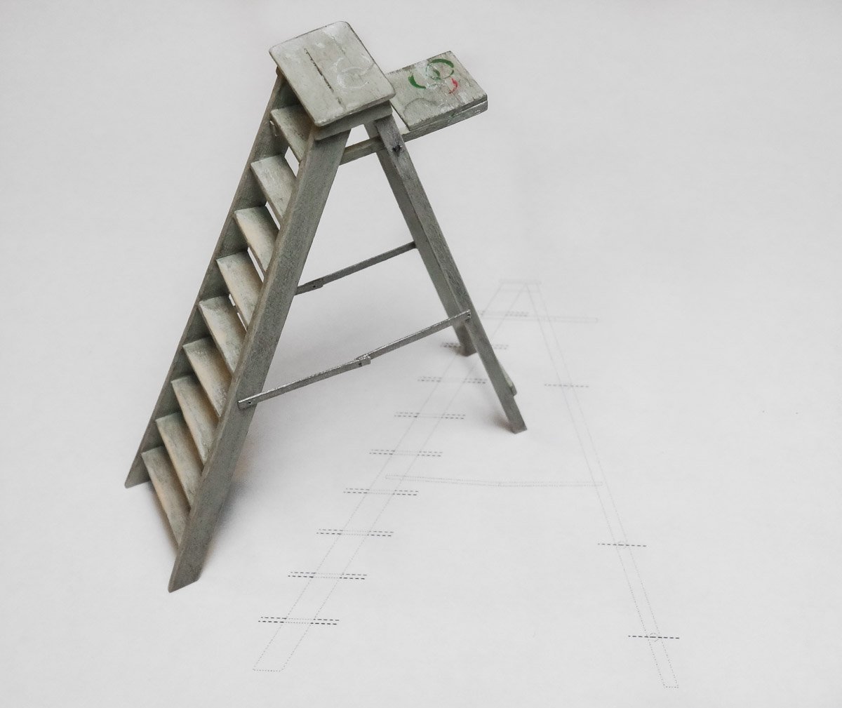
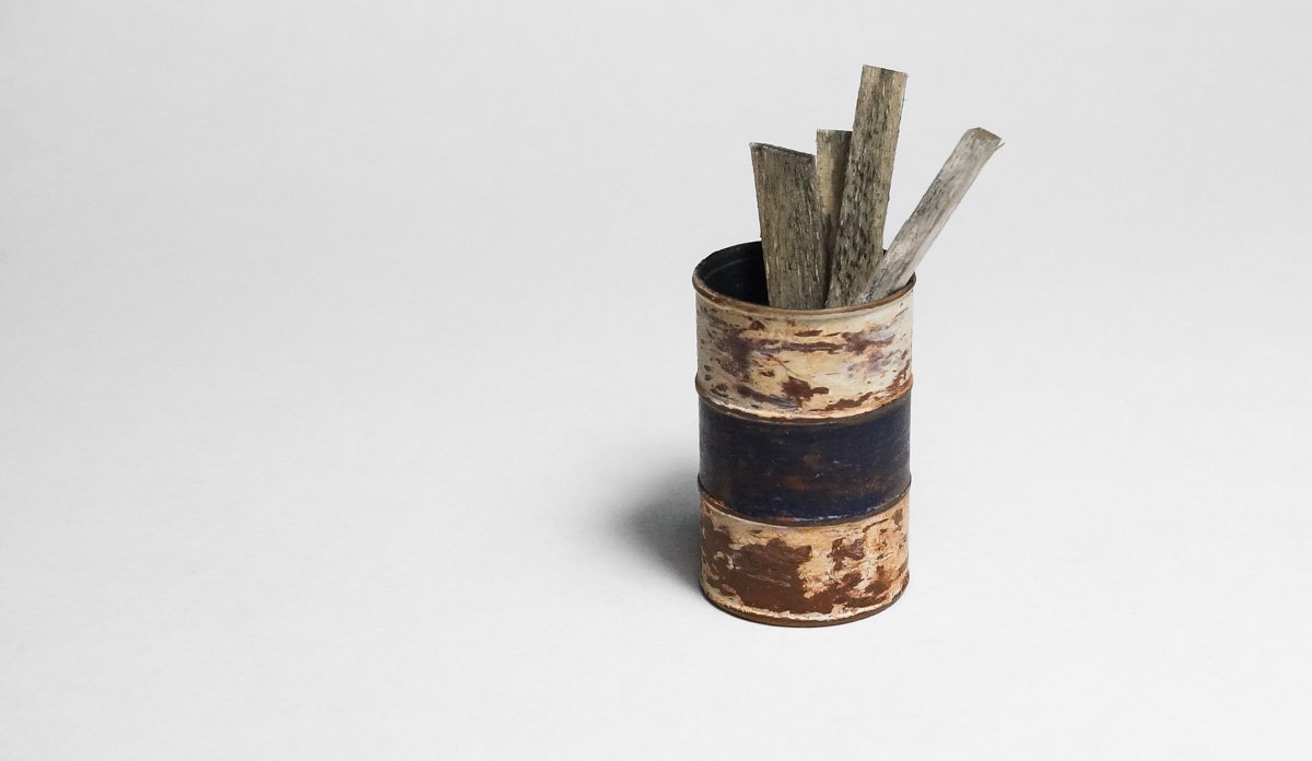
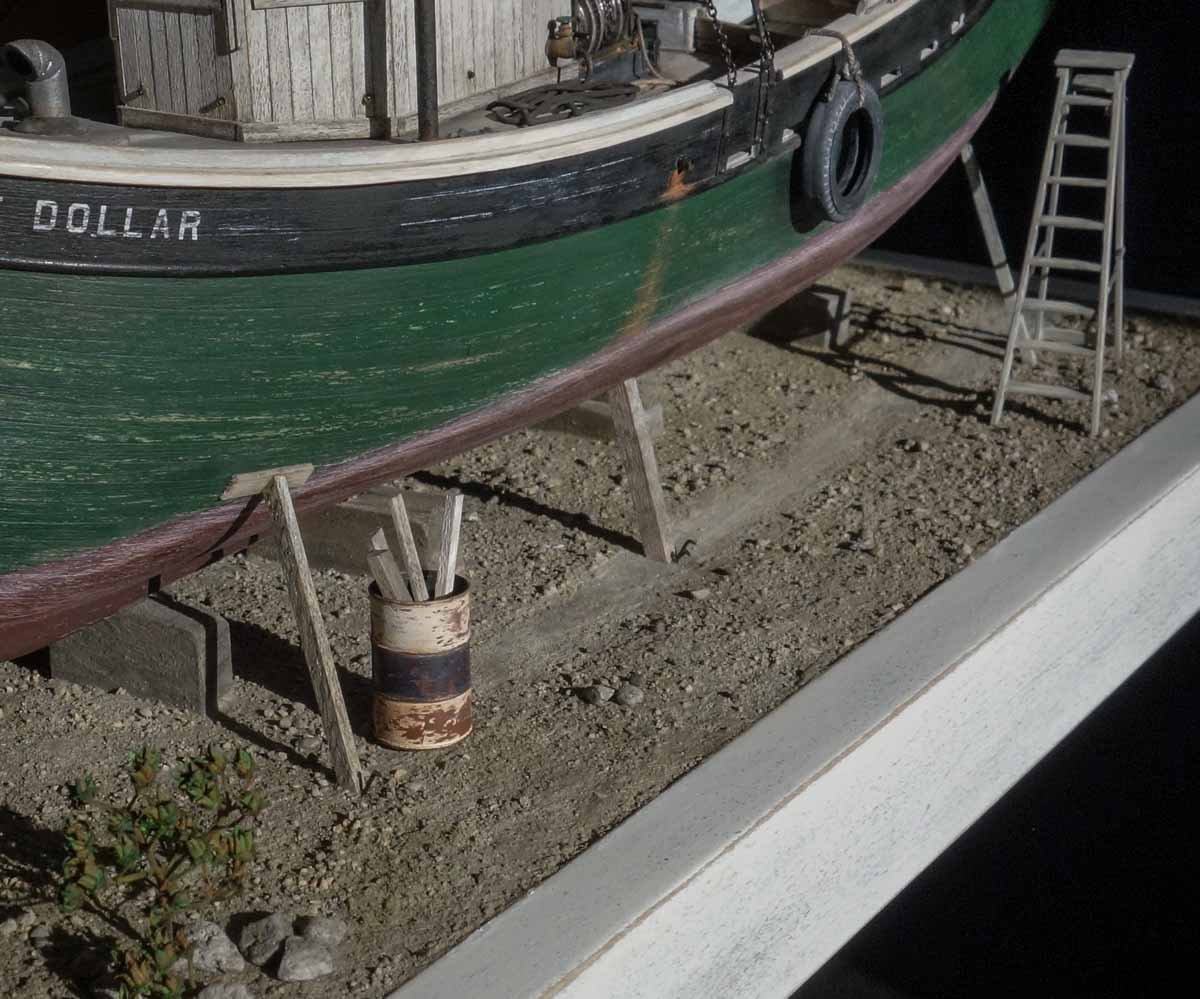
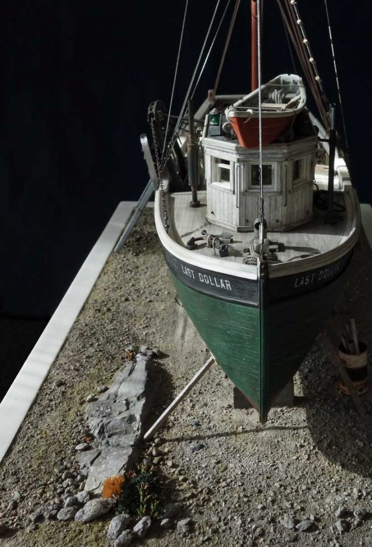
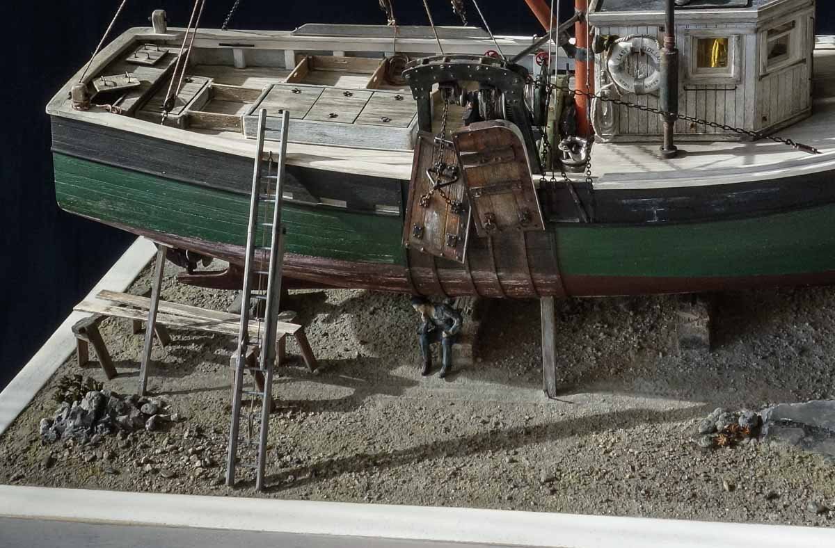
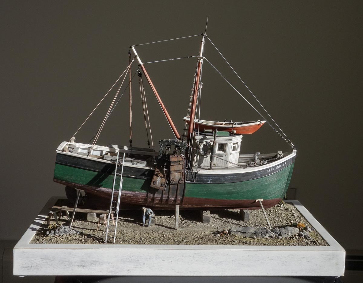
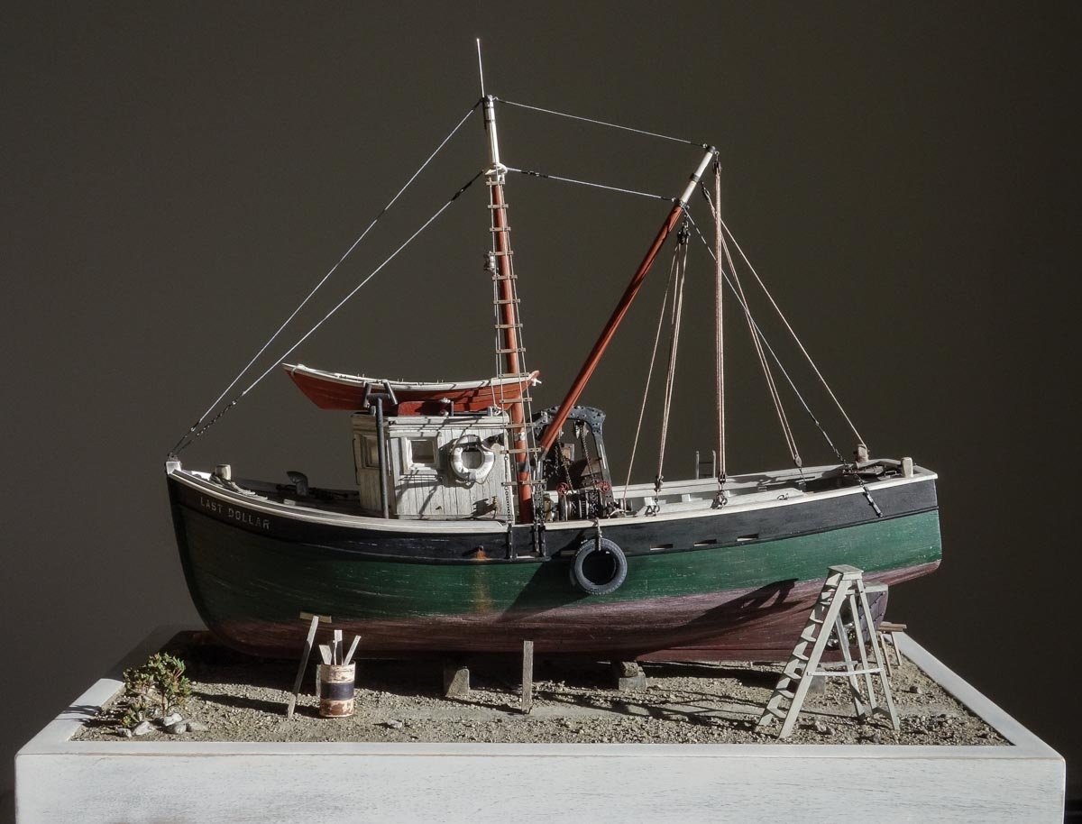
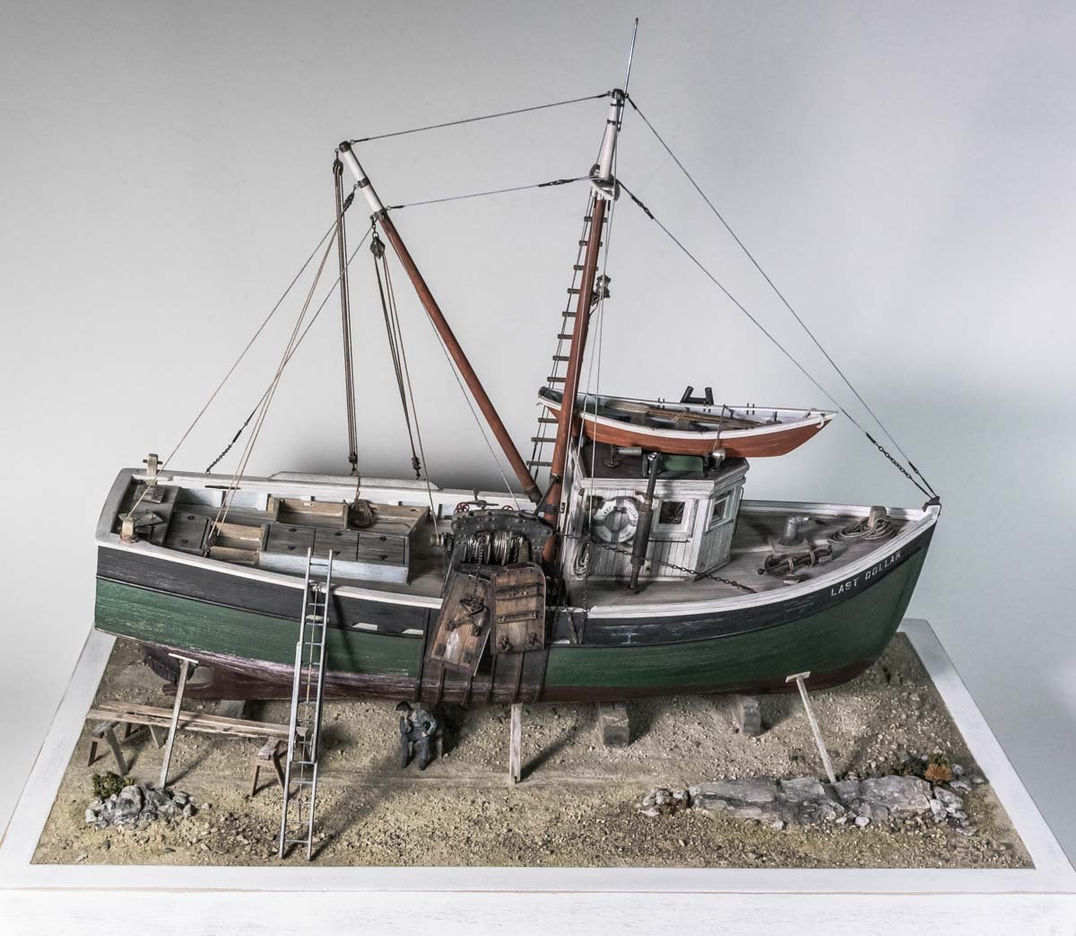
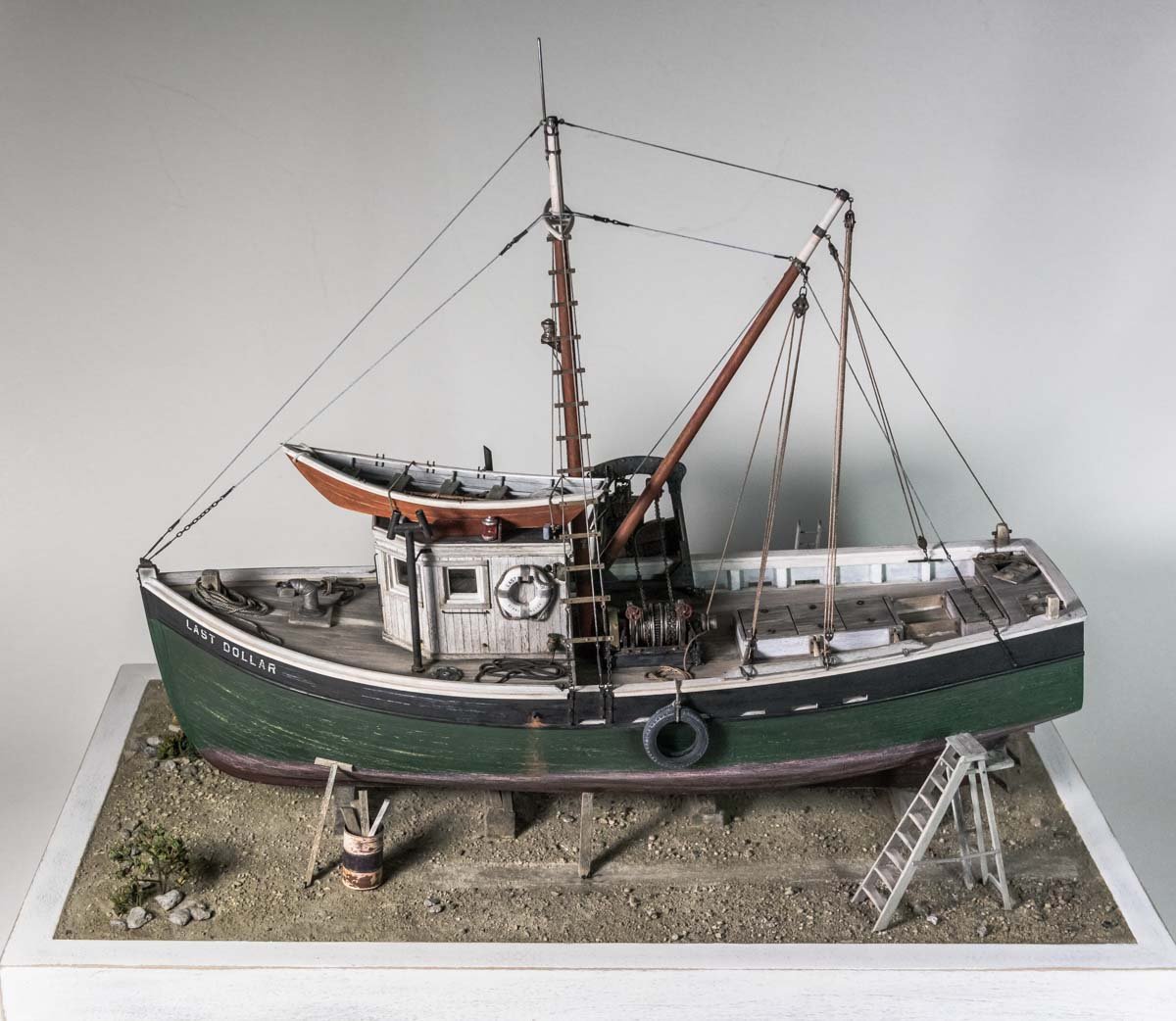
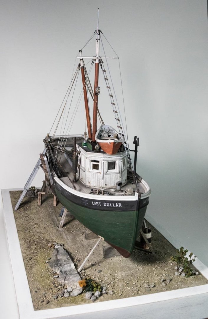
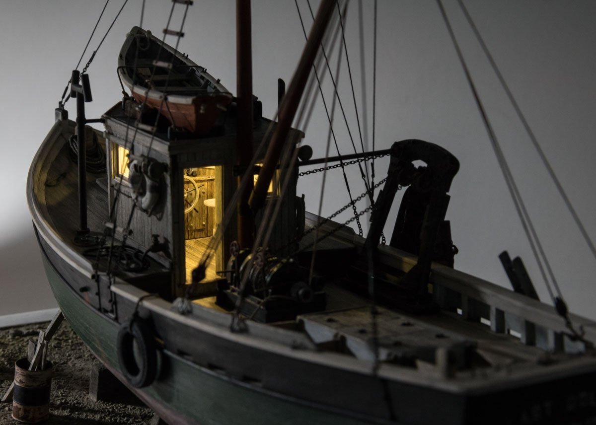
Thanks to all for the comments and the likes – it is always greatly appreciated. Hello Ron. I'm glad you found my log and thank you for the kind words. Thanks also for the comments regarding the dory, but I'm going to respectfully disagree on the dory's purpose for the following reasons. First, as I researched these small western-rig boats, I found references to the roof mounted dories as indeed being lifeboats. I agree with you that present day F/Vs mostly do not carry lifeboats, only inflatables. But even as late as the 1970s they did. In Peter Prybot's book, White-Tipped Orange Masts: (Gloucester's fishing draggers in the 1970s), the author states that the eastern-rig boats carried two life boats atop the pilothouse and smaller boats carried one. Here is an image of eastern-rig boats in Boston in the 1960s/70s all carrying dories painted in the same high visibility color. The image above doesn't prove anything by itself, but it shows that the boats were common in an earlier time. As the decades passed and the dories became increasingly rare, it must have been due to the movement toward CO2 canister inflatables. If the dories were part of the fishing gear, they would not have vanished because the basic method of trawl fishing during this period didn't change. A second reason I believe the dories on these small draggers were not part of the fishing gear is that I have never read where auxiliary boats have ever been used in conjunction with otter trawl gear. I don't see how the dory would assist in that process or what it could do that the winch or boom hoists could not, especially considering the weight of the gear (wire rope, otter boards, roller gear, etc). And my final thought is that without a davit, getting the dory down off the roof and back up routinely seems impractical. Of course I could be totally wrong about all of this, but certainly without some way out of the frigid New England water, a person would quickly suffer from cold incapacitation followed by hypothermia in short order. Thanks again Ron. Finished This simple diorama base has been a painfully slow slog. I re-did it several times with each version being tossed into the trash. But I have surrendered and it is done. I began with a framed platform that measures 7.5” x 13.5”. Like the model, it shows signs of wear. I then made a landscape foundation of Hyrocal. This is great stuff – mix with water and it cures hard as a rock, doesn't shrink, crack or flake apart. I poured this mix onto a piece of waxed paper so I could work the stuff away from the base in anticipation of do-overs. The rock out-crop is also Hydrocal that I formed in a flexible mold manufactured by Woodland Scenics. Trailer tire tracks are laid in. I glued the slab onto the base with crazy amounts of PVA and filled in around the perimeter with a fresh batch of the Hydrocal. There is an interval of time before it has cured (hours) where the stuff is “green” - hard, but very workable with carving tools. I then cut and glued down the wood blocks that will support the boat. Slide switches and a battery holder for the LED lighting are mounted to the underside. The Hydrocal was painted with a brown gouache and then landscaping materials are added on top. The rock out-crops are also colored with gouache. The “dirt” is pulverized cat box absorbent (unused mind you). It's placed into a plastic zip bag, smashed with a hammer and then sifted into piles - powder, fine and course. The scant vegetation is dry bits of things from the flower garden that were then painted with acrylics. And the scattered rocks are, well - small stones. Once things were arranged to my liking, I sprayed wet water (more like a heavy mist) over everything until good and wet. This helps the adhesive to flow. Before it had a chance to dry, I used a craft style syringe/eye dropper and applied a 50/50 PVA/wet water mix over the entire diorama. A lot of this mixture was applied- everything soaked but no puddles. Below is how it looks when dry. I can shake it vigorously upside down and nothing falls off, but that's not a recommended practice. I make up a few details. An extension ladder colored with acrylics and pigment powder. And a step ladder. A 55 gallon drum filled with scraps. The drum is injection molded plastic from Tichy Train Group. It is based painted rust enamel then over-painted with acrylic, chipped and pigments applied. So I grab the boat and bring it over to the base for final mounting. Before I make it to the base, I sneeze violently and the boat jumps from my hands like it was possessed. I watched in slow motion horror as the model pitchpoled end over end and landed on the floor like a cat, right side up and flat on its keel. I could barely believe my careless stupidity or my undeserved good fortune. The model remained in completely undamaged condition with only the engine stack having been slightly loosened. Sometimes the gods smile upon you. The LED wiring is run down through holes in the wood blocks and the boat is attached to the base. Details are glued on and boat stands are added. A worker in a pensive moment contemplates the world and his place in it. The figure is by Arttista. And at the last minute I decided the scene needed saw horses and a couple of planks. And some other direct lighting shots. Some indirect lighting photos. Well, this model is finished and it has been a pleasure sharing it with you. I thank everyone who looked in on the build and all the folks that clicked the “like” button. And to all of you who have generously given comments of support, suggestions, information and expertise – I thank you so very much. Be safe and stay well. Gary


- 424 replies
-
- 51
-
-

-
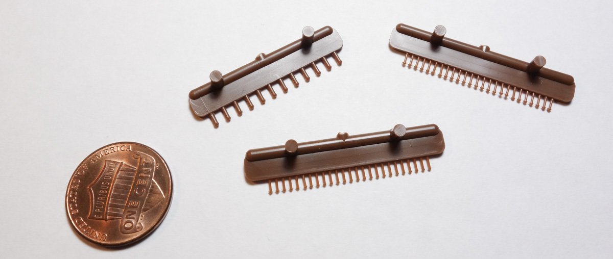
Hey Eric, Another way of adding rivets is to purchase injected molded rivets. I use them quite often and have a selection of sizes. Tichy Train Group manufactures them and they range in rivet head diameter from .02" to .08". They are available with round or conical heads - $3.00 for a package of 96 or 200 rivets (depending on rivet size). https://www.tichytraingroup.com/Shop/tabid/91/c/o_nbw-rivets/Default.aspx The largest ones shown below are the .04" size. Just another option. Gary
-
Ditto, Ditto, Ditto Your model is looking very good Paul. Gary
- 87 replies
-
- 3
-
-
- bluejacket shipcrafters
- red baron
- (and 3 more)
-
You never disappoint Keith - in the creativity of the process, or in the beauty of the result. Great stuff! Gary
-
Wonderful work Ekis! You seem to be ever raising the bar on your own work. Each new post is more detailed and more perfectly executed than the last. Nice. Gary
-
Wonderful work on the pumps Richard! Simply superb sub-miniature machine work. So realistic and crisp - love it! Gary
-
More beautiful work Valeriy! I ditto Druxey's remark - "That is the nicest miniature shackle I've seen." Thanks for showing us how. Gary
-
Beautiful work Siggi. I very much like the pumps and I am always impressed with your crew figures - extraordinarily fine, especially at 1:48. Gary
-
Hello James. I’ve been checking out your log and I think your model is coming along very nice indeed. The detailed documentation you’re providing is going to be really helpful to other modelers of this kit. You are determined and working carefully and will end up with a great first model. Gary
- 32 replies
-
- 1
-
-
- red baron
- first build
- (and 1 more)
-
Nice work Allen - she is looking sweet! I really like that wood tone with the white. It’s so clean and cheerful. Hand rails look great too. I must try your scraper method sometime. Scrapers are commonly used in furniture finishing and I can see where the technique would work nicely on fine wood modeling as well. Gary
-
Just read your log from the beginning Paul, and you're progressing nicely on this model. Bluejacket makes a great kit, but it still requires dedication and effort (just as you are doing) to produce a really fine model. First time builds are difficult, but going forward you will build confidence and I'm sure the end result will be beautiful. Keep at it and watch out for rolling knives. Gary
- 87 replies
-
- 3
-
-
- bluejacket shipcrafters
- red baron
- (and 3 more)
-
That's something I hadn't even considered, but it's a nice easy detail to add as the tires are not glued down. In fact I won't even need to untie them. Thanks Kurt. Hello Wefalck. Hello Keith. Thank you both for your comments. Yes the coal is for the galley stove as Keith has stated. The stove provides not only the means of cooking, but obviously it provides heat for the crew, the berths and also the wheelhouse. And New England winters can be quite cold, especially 100 years ago. The size of my scuttle is about 15” diameter (dictated by the tubing it was cut from) and is slightly larger than the 14” diameter of the Thomas Laughlin Co. coal scuttle that I used as a size reference. Of course that is the outside diameter of the deck flange and the actual usable opening would be smaller. I don't know how the coal was delivered – shoveled out of a cart, sacks? But the size of the scuttle doesn't strike me as being overly generous considering the material. The alternative would be through the wheelhouse and down what can only be considered a glorified ladder. It is interesting to think through how ordinary tasks were accomplished in a much different time. Thank you both again. Hello Bedford. Thanks for the very interesting reply. I am surprised that the tug pulls to port with no tow and to starboard with a tow. I would not have guessed that and it convinces me that even things that seem simply on the surface usually are not. It could very well be that the boats trawl in an arc or as you say a sweeping circle (actually, that vaguely rings a bell.) And boy that has to be fun to crew on a 1902 steam tug! Druxey, John, Bob, Paul, Richard and Allen - Thanks for the nice comments. Gary
-
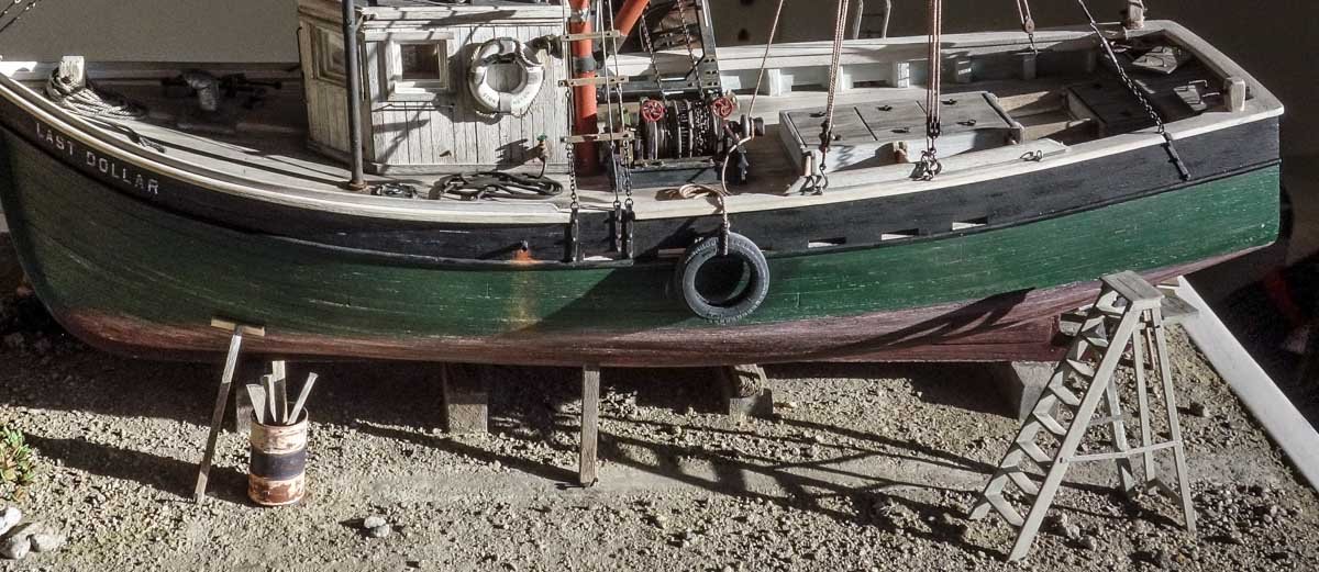
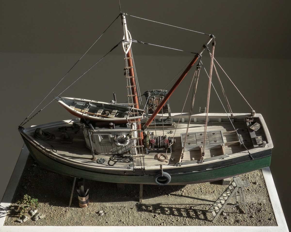
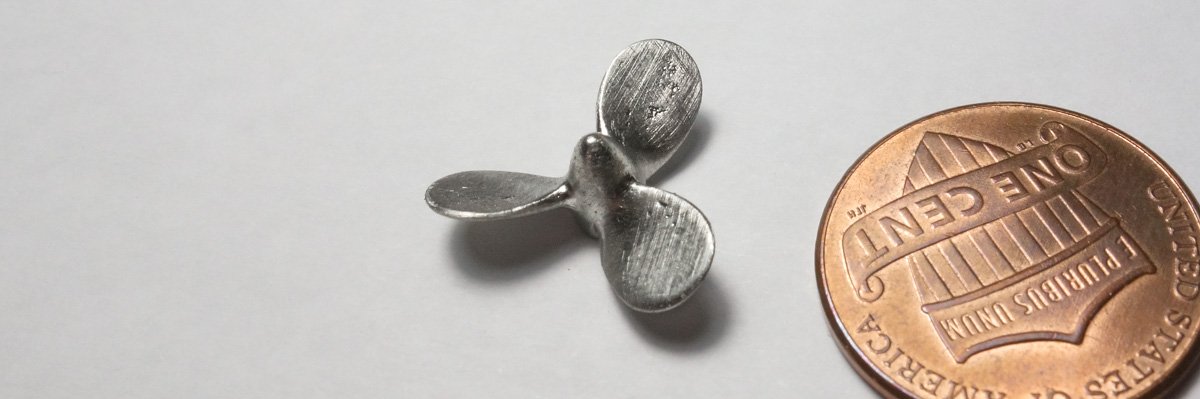
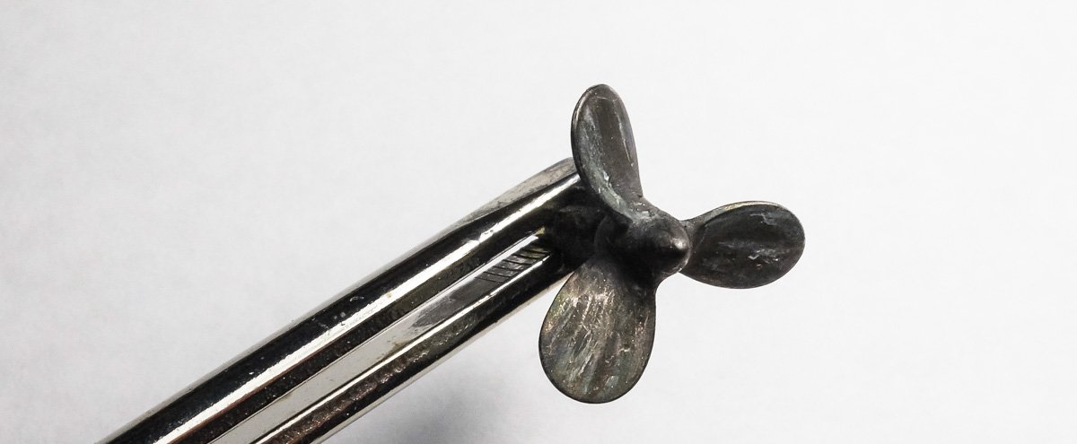
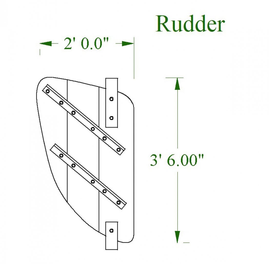
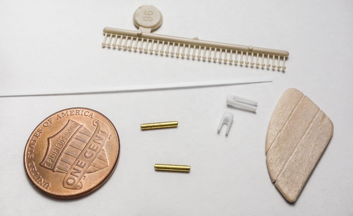
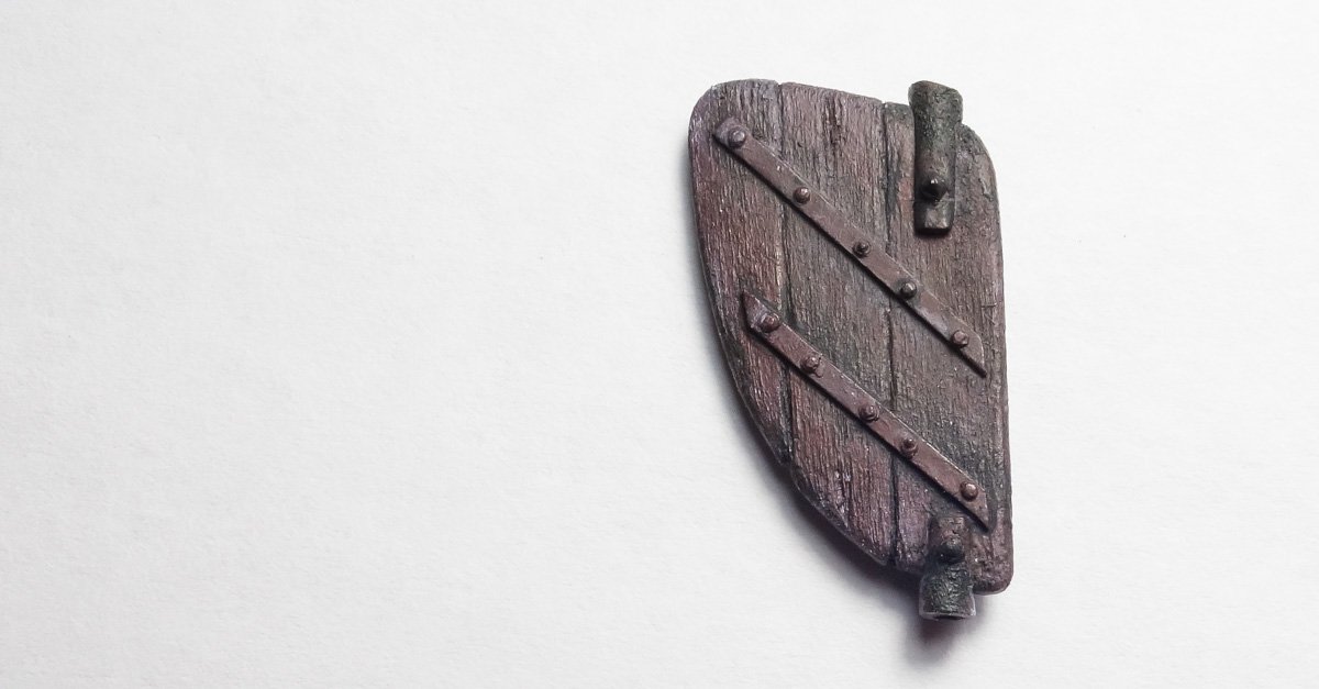
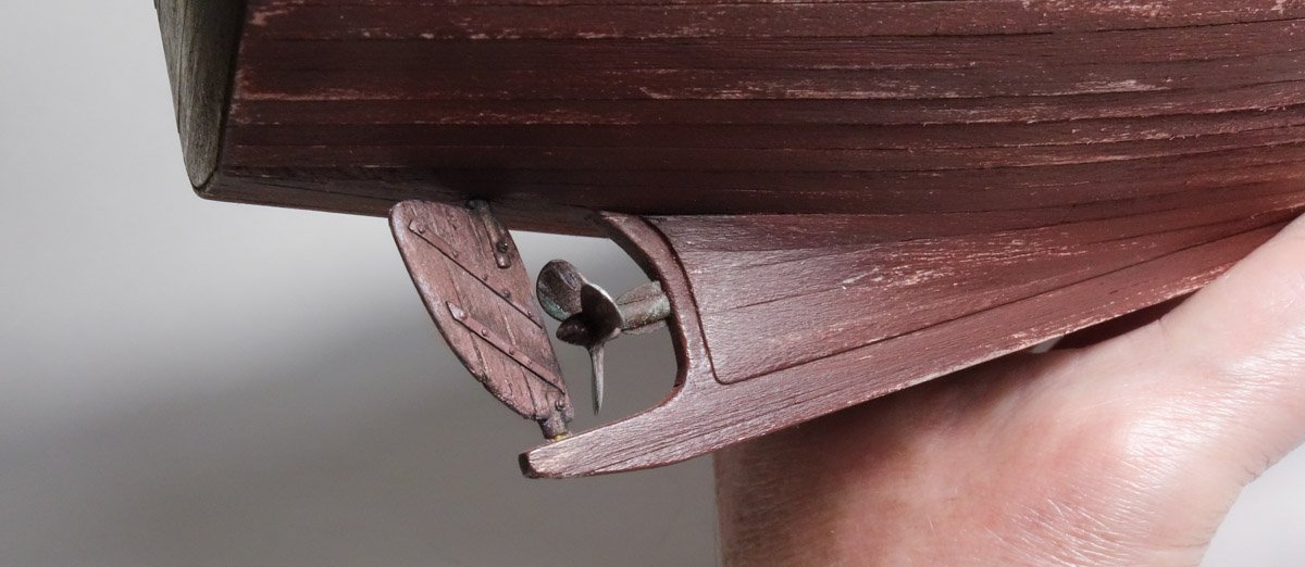
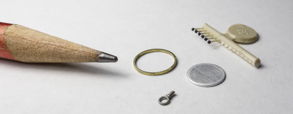
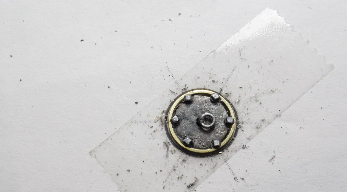
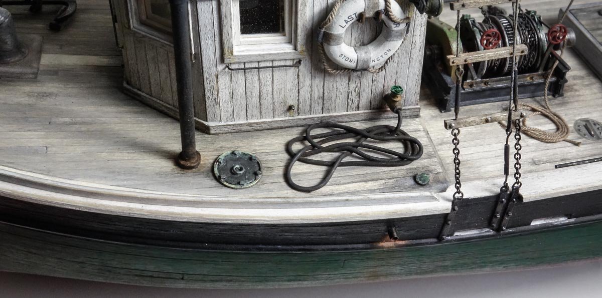
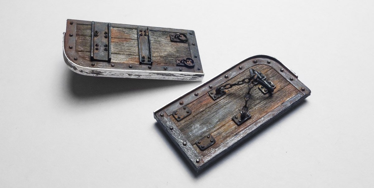
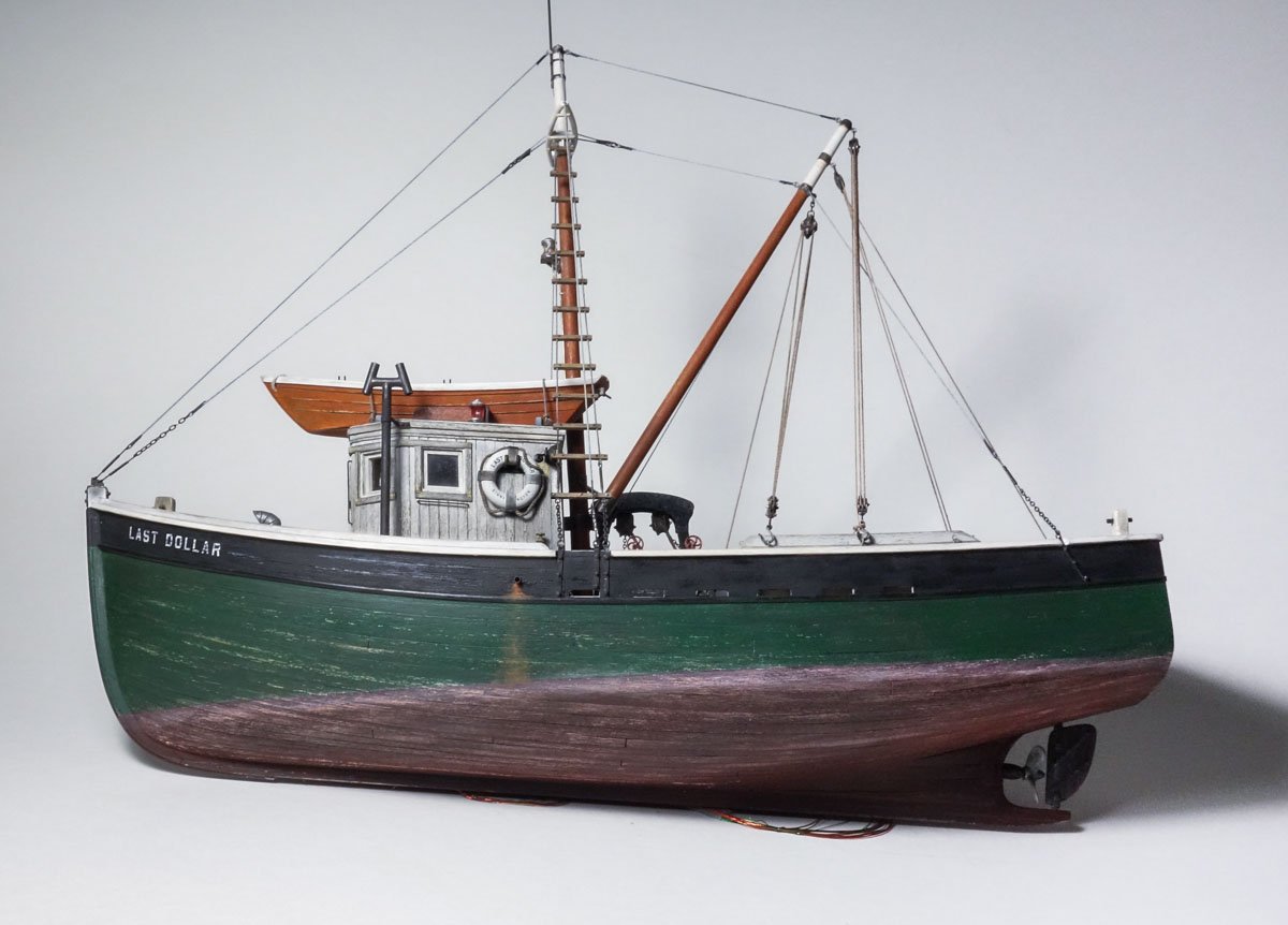
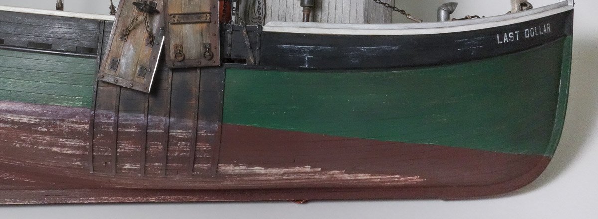
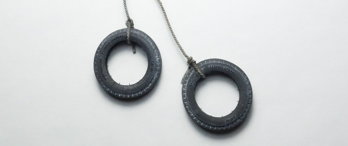
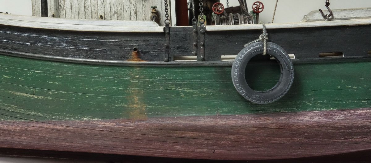
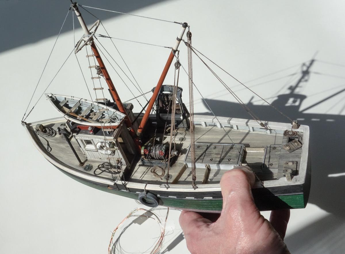
Thanks to all for your wonderful comments. And thanks for the likes and to those watching quietly. Some Final Odds and Ends These boats almost universally used a 3 or 5 blade right-handed propeller in the 26” to 30” range. The prop I'm using scales to about 26” and is from Bluejacket Shipcrafters. I had intended to scratch my own, but I found this prop in my stash box and my inner lazy-slug voice talked me into using it. So I cleaned it up with file and sand paper. And then added some evidence of use. My understanding of prop walk is that the dynamics of a right handed propeller will hook the vessel to port as it moves forward. The effect is more pronounced in reverse but still evident going forward. So I have this question that I have found no definitive answer to. Is this prop walk the reason all these boats drag off the starboard side - to counter this hook to port? At least it's not adding further to the tendency to pull to port as it surely would if they were dragging off the port side. Or is this prop walk insignificant compared to the other forces involved here? What do you think? After looking at a couple of dozen rudders, I drew up this one. Prepared some bits and pieces. Then assembled. Acrylic paint and pigments are applied. Glued to the boat. I then prepared parts and pieces to assemble a coal scuttle. The scuttle diameter is approximately 5/16” or 15 scale inches. The lid is painted and held captive within the brass ring with a dab of epoxy. Holes for the bolts and lifting ring are drilled and the bits glued on. Scale 4” fuel fill deck plates are punched from brass shim stock and painted. The paint is mottled to suggest detail that isn't there. A engine cooling water discharge pipe is cut from brass tube and the end is reamed to reduce the pipe wall thickness. In the image below, all three of these items are shown; the scuttle, one of the fuel fill plates and the cooling water discharge. There also would have been a fresh water fill plate, generator cooling discharge and other items, but . . . Some time ago back on page #9 of this log, I built the Otter Boards for the boat. So it is time to hang them off winch chains. They are lightly glued to maintain their position. The hull is painted with acrylic Tamiya Hull Red (XF-9). I don't have a lot of Tamiya paint so I forget how nicely this paint lays down, how well it covers and how smoothly it brushes on. It's like painting with thin mayonnaise. The surface of the hull was then scraped and India ink/alcohol was washed on top. I then added a water line stain with thinned white acrylic. And then some sanding. I played around with simulating barnacles, but I was never really happy with my results to where I thought it added in a positive way to the model. So I'm leaving the hull in this pre-paint prep state where the marine crud has been mostly removed. I think this will work as the model will be displayed in dry dock in the process of getting new bottom paint. Here on the starboard side the bottom painting has begun. Old tires were often used as fenders on these boats and still are on modern F/Vs as well. I found some vinyl 1:48 tires on ebay that have hollow interiors and raised lettering. I put these tires in my portable drill and stripped off all the tread with a needle file. These tires were already black, but they were too black and shiny, so I re-painted them with my own dull charcoal mixture that looks more to scale. I then gave them a white acrylic wash. Because they are hollow, I was able to place a piece of blackened copper wire inside to form them into a slight out-of-round shape. The ropes wrap around a cleat and hang over the rail. A subtle rubber abrasion against the hull is added with pigment. I haven't decided yet how many of these tires to place on the model. Just a couple maybe – after all, it's not a tugboat. I guess I should add some rope abrasion to the rail as well. I've begun working on the diorama base, so in a couple of weeks I'll have one more posting to share with you. Thanks for taking a look. Be safe and stay well. Gary


- 424 replies
-
- 33
-
-
Congratulations Chris - she turned out really great. Beautifully built model of a interesting vessel. Gary
- 179 replies
-
- 4
-
-
- shipyard
- wütender hund
- (and 1 more)
-
Just catching up Ekis and I see you’ve made great progress on the village. This most recent structure has some very complicated facade detailing, lots of half-timbering. Looking very nice indeed! Gary
-
Terrific modeling as we have all come to expect Keith! I particularly like the recycled use of the disk tray - resourceful and clever. Gary
-
Spectacular work! I’ve seen very few modelers who can successfully include this level of detail at so small a scale. And the fact that this sub-atomic modeling is also realistic is truly exceptional. Very nice! Good call - don’t cover up the magic. And I echo Marks’ comment that even pointed out, I don’t see the errors. Gary
-
Sweet work Ekis - very nice progress. Gary
-
Hello Richard, I’ve been reading your build log from the beginning off and on over the past few days and have just now caught up. To simply say that I’m impressed with your skill and craftsmanship would be a gross understatement. Your work is superb. The detailed upgrades and replacements you’ve made put the kit supplied parts to shame. I particularly like the windlass, gears, pawl and other mechanics. Great stuff. I’ll be watching for future updates. Gary