HOLIDAY DONATION DRIVE - SUPPORT MSW - DO YOUR PART TO KEEP THIS GREAT FORUM GOING! (Only 51 donations so far out of 49,000 members - C'mon guys!)
×


FriedClams
-
Posts
1,368 -
Joined
-
Last visited
Content Type
Profiles
Forums
Gallery
Events
Everything posted by FriedClams
-
 Very nice job on the guns Keith - the truck carriages turned out great. I wasn’t aware of your stroke of a few years back, but it looks like you have made great progress in your recovery. The difference between the middle gun and your new guns is quite striking. Glad to know you have fought your way back and are clearly much improved. Looking forward to see how the sweeps go on. Gary
 -
Welcome back Keith, if only for one day a week. Nice progress on the deck house and as always I look forward to your future updates. Gary
-
Eric, I completely agree with what Mr. L Fly has stated above. Your persistence in understanding and correcting the problems you’ve had with this kit is admirable. I’m happy to see that you didn’t surrendered and kept seeking solutions. Hopefully you will have enjoyment in its construction as you move forward. Very nice paint work on the figures by the way. Gary
-
She is a beautiful schooner Allen and you're hull construction and planking is very nice indeed. A great start on a handsome vessel. I will be watching for updates. Gary
-
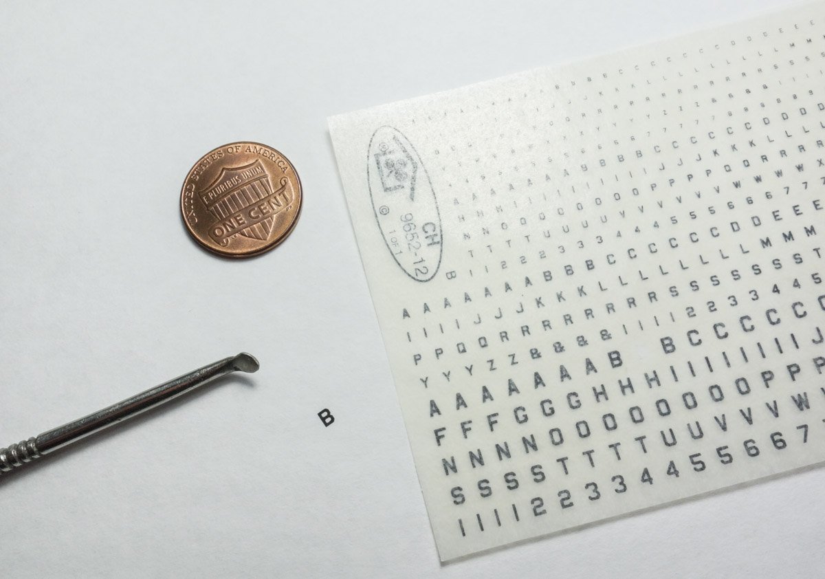
Thank you Keith A and Keith B. Hi Ken, thanks for the nice words. No I don't cut them out as the carrier is helpful in locating the character. The horizontal rows of letters can be used as a reference for level against letters already placed or against the edge of a plank, etc. Holding the carrier by its edges allows for easy orientation vertically, horizontally and even in rotation. For example, after determining character spacing for the boat name displayed in an arc, I position a letter so its bottom center rests on the arc equidistant within its allotted space. I then place the point of a dressmakers' pin at that bottom center point (not really penetrating – just holding the placement.) This is now used as a pivot point and I rotate the carrier film until the letter orientation pleases my eye. I then place a finger somewhere on the film to keep it from shifting, let go of the pin and rub the letter down. After a few minutes messing around with these transfers, you'll have it down. I've seen people rub transfers on like they were using a pencil eraser, fast and unexacting. I've learned slow firm pressure, moving deliberately over the entire surface of the character produces the crispest results. Hope that helps. Hi Mark, Yes they are rather old school, but often - they're just the ticket. I understand that a few companies will now print custom color transfers of any text or software generated artwork. But last I checked, it is crazy prohibitively expensive. Thanks for stopping by. Gary
-
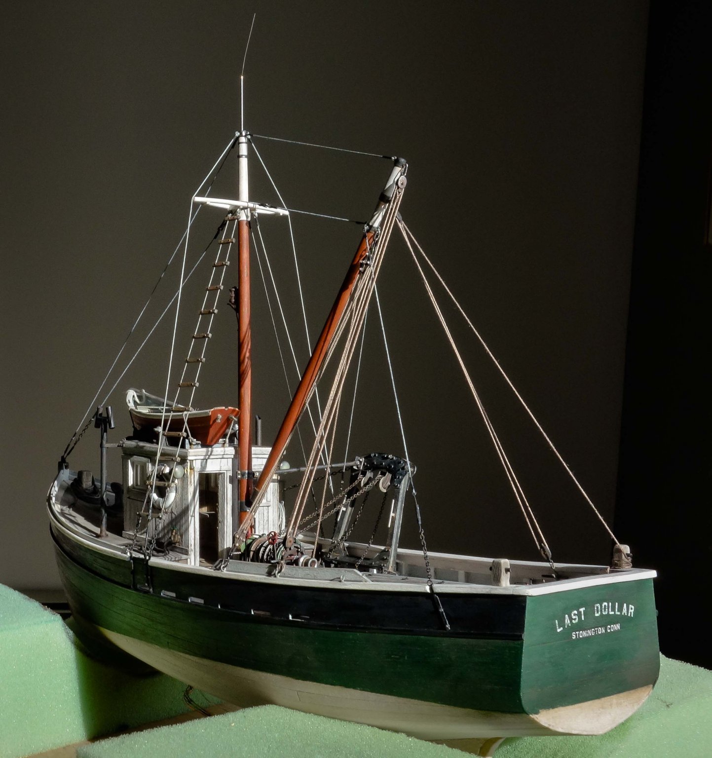
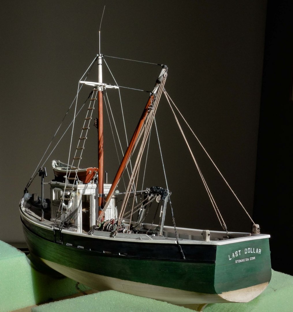
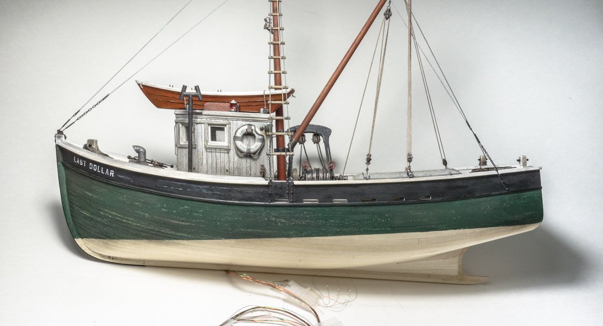
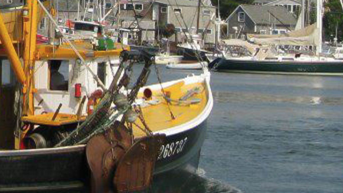
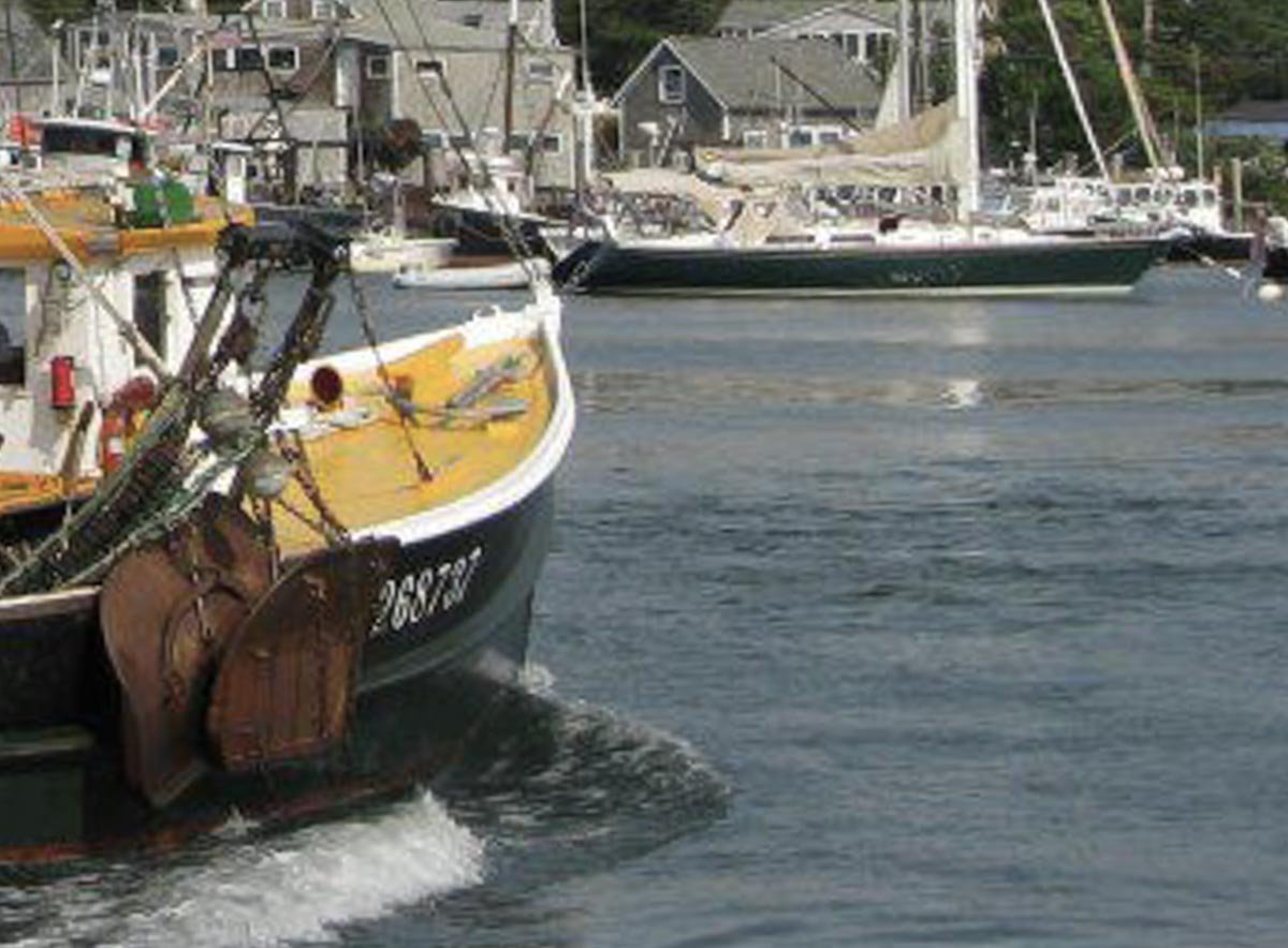
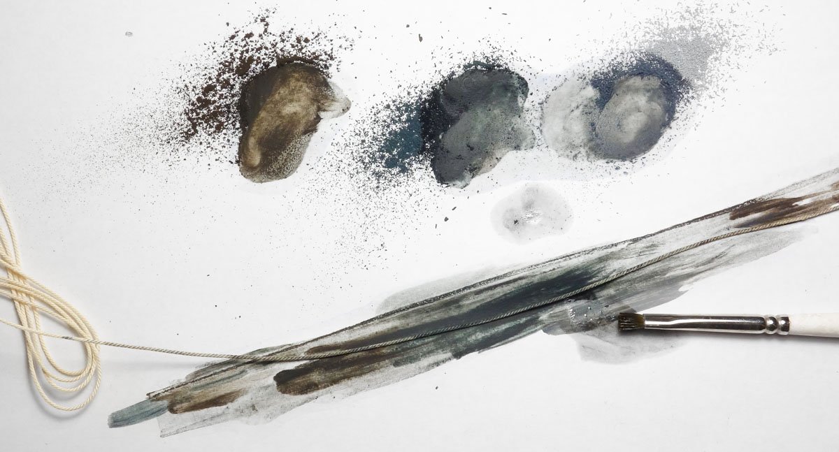
Yes I agree, multiple dilute washes can produce some very nice results and often gives the surface added depth as well. For me, weathering is always a trial and error exercise and adds much time to a build – but the process is fun. Thanks Wefalck. Hello Keith. Thanks for the nice comment. Here is a photo in the same light and similar angle that shows the whole boat. The stern is overexposed but otherwise not a bad image though a little noisy. It is a crop and I did compress the file for uploading, but there is a little zoom left in it. Thanks again Keith. Hi Allen – nice to have you looking in. The lettering is not peel and stick, but rather it transfers to the surface by rubbing them on. The transfers have a pressure activated adhesive and are attached to a carrier film that is peeled off once the letter is transferred. You simply position the film so the letter lands where you want it and then firmly rub the back side of the film over that letter. I use the convex side of a small spoon shaped dental tool to rub them on. In the photo below, I transferred the letter “B” to the copy paper background and as you can see that letter is now missing from the film. The letters are not a solid piece but rather a kind of toner, so only the portion of the letter that is rubbed gets transferred leaving behind the area that wasn't rubbed. Dry transfers adhere better to flat surfaces than to gloss surfaces, so a clear coat is needed when used on gloss. On my stern lettering, I can briskly rub the pad of my finger over the transfer and nothing happens. If I scrape it with my finger nail, it will remove that portion of the lettering. Before I am done I will likely cover the lettering with a thin flat coat and then soda blast it to remove any remaining sheen. My only experience with dry transfers is with those from Clover House but I assume transfers from other companies have the same basic characteristics. Also be aware that some clear coats can attack and dissolve dry transfers so experimentation is needed. A quick web search will reveal many sources of dry transfers in all sizes and colors. You might even be able to find some at a local craft store to try them out. I'm not a big fan of water slide decals as they stand proud of the surface and the edges can be difficult to disguise. I have seen modelers use decals very effectively, but whenever I have used them, I can always find some angle of light that betrays them. That is not an issue with dry transfers. Sorry about the wordy answer. Hello Chris. Yes I agree craft store paints due have limitations, but as you mentioned they worked out OK in this application. I saw a model once where a heavy layer of this craft paint was laid down and the modeler then chipped and scrapped chunks of it off here and there and then painted over that. So all the underlying damage telegraphed through the fresh new top coat in 3-D fashion. Very cool. Thanks for stopping by. Hi Mr. Storm. I'm glad you found my build and hope you find something useful here. Hello Richard. Thanks for stopping in to check out my build and for the kind words. Weathering is fun and often unpredictable, but I enjoy it. Hello James, glad you stopped in. I can eat my weight in fried clams. Druxey, Ekis, Paul, John and Jean-Paul - Thank you so much for your fine comments. I always appreciate them. And thanks to all for the likes and for looking in. Gary
- 424 replies
-
- 13
-

-
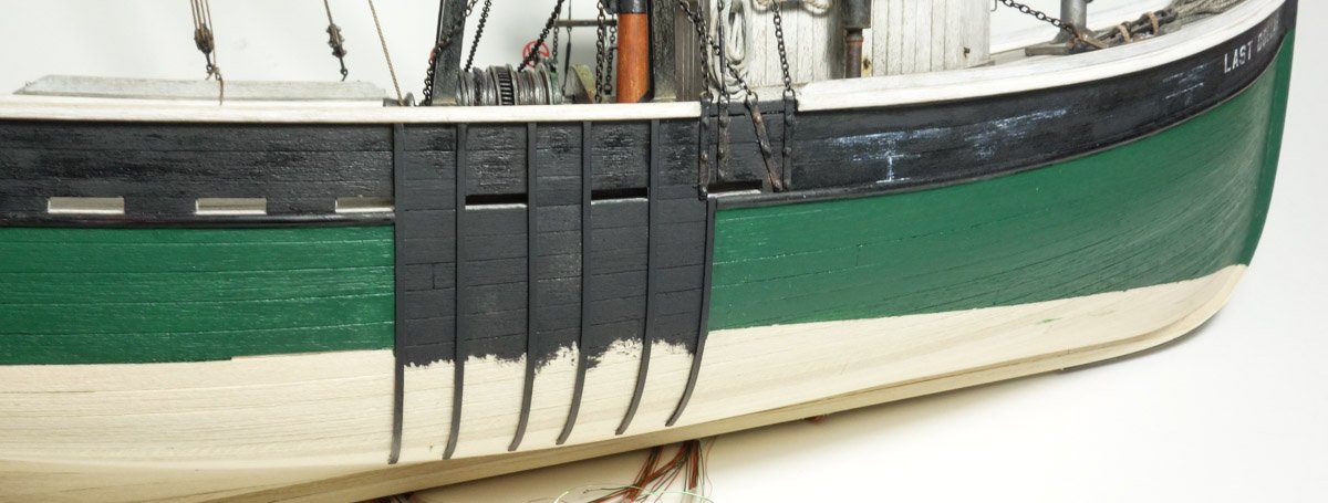
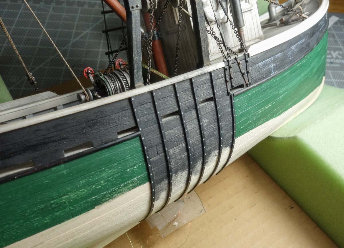
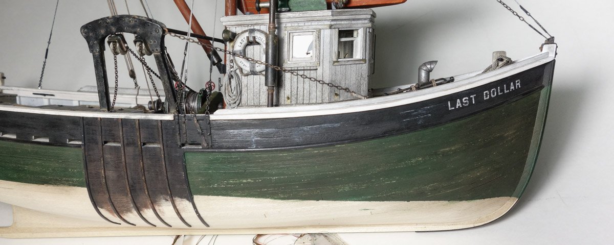
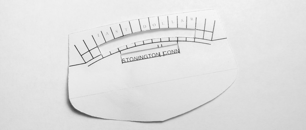
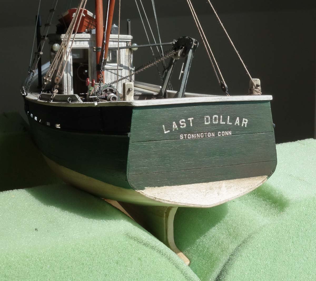
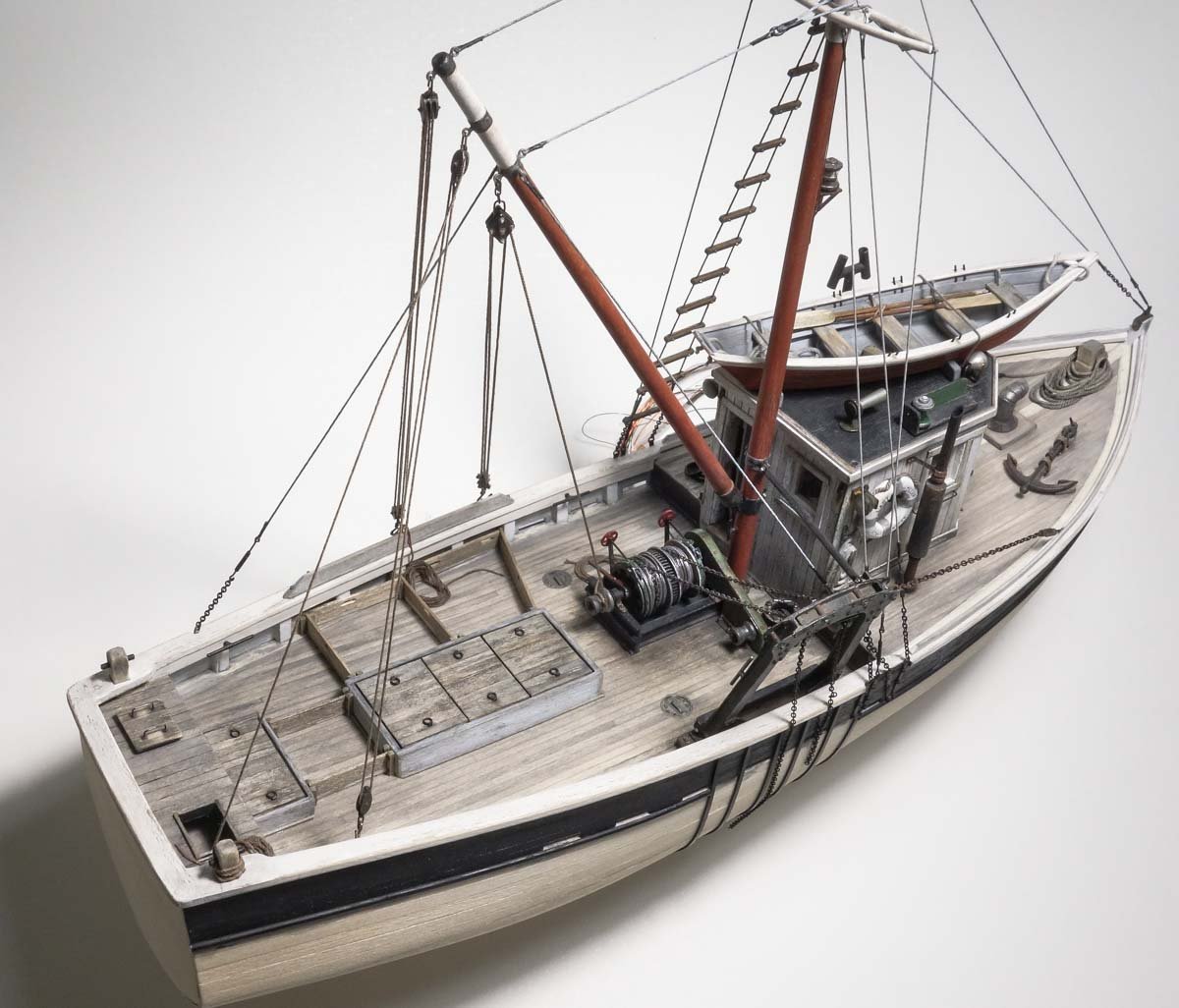
Thanks to all for the wonderful comments and taking the time to make them. And thanks for the likes. Some Hull Paint Weeks have flown by and yet I have little progress to report. But here is a brief update on the model. Many of these boats were painted dark green above the water line and so my model will also be green. I began with a emerald green to which I incrementally added tiny amounts of real black until I had a sort of hunter/forest green. (I am always amazed how the slightest amount of black can totally overwhelm any color). I didn't want a green that leaned yellow, so I added a drop or three of purple because the color wheel tells me that it is the opposite of yellow. This gave me the base color I had in mind. The paint I'm using is inexpensive craft store acrylic and it has a sheen to it which will be gone by the end. The image below is over-exposed to better show the color. After the paint thoroughly dried, I scrapped the surface with the edge of a razor blade. Also, I drilled a series of shallow holes into the strapping that protects the hull from the otter boards. This is meant to represent the flat head screws that hold the strapping in place. Continuing with the weathering process, I went back and added brush swipes (here and there) of a darker value of the same green. I then washed the entire painted surface with a India ink/alcohol solution which visually softened the scrapped areas, lessened the contrast and dulled everything down. The alcohol in this wash makes this step a “one and done” application. It quickly softens the acrylic and any lingering or second brush strokes risks re-liquifying the paint and returning the surface back to a uniform color. Finally, I scrubbed it with brown pigment powder and then finger rubbed the entire surface. I also gave the hull strapping area some preliminary color, but more work needs to be done there once the otter boards get hung. The name and home port was placed on the boat. I made up a locating template in CAD to assist in placing the letters. Dry transfer lettering is applied. The stern looks like it could use a bit more wear. This final image was taken with direct lighting pointing at the hull from a low angle in attempt to show what the weathering looks like. In normal viewing the effect is less pronounced. Thanks for stopping by. Stay well. Gary
- 424 replies
-
- 30
-
-
The beautiful work continues. Your town is growing and looking great Ekis. So interesting and fun to follow. Gary
-
Capturing the essence and still makeable - that is difficult in larger scales - in 1:120, it's crazy hard, but you're managing quite nicely. You have nailed the shape and proportions of both cannon and carriage Keith. I look forward to seeing the carriages painted out and component bits added. Very small and very nice - the bottom photo says it all. Gary
-
I've been checking out your build on the Pen Duick Bob and I'm impressed with the execution and fine fit you're achieved. The hull came out spectacular and what a beautiful paint job! I'll be keeping tabs on your progress. Very nice work. Gary
-
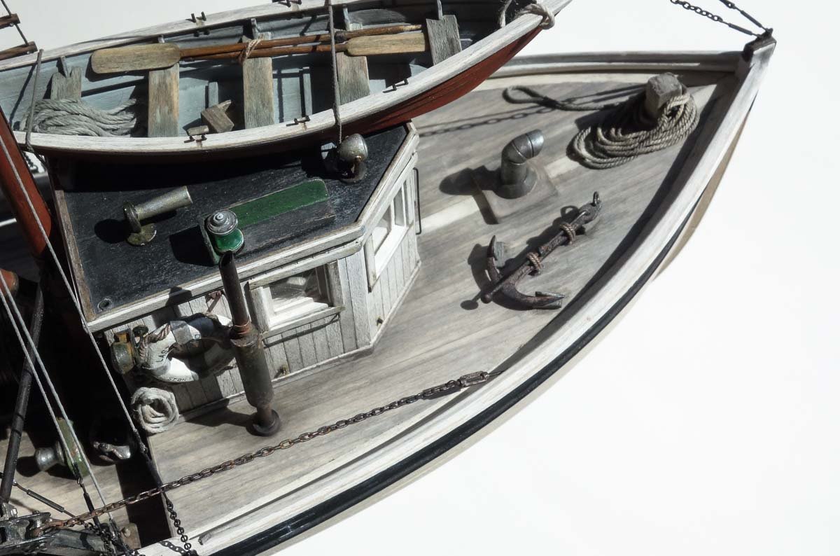
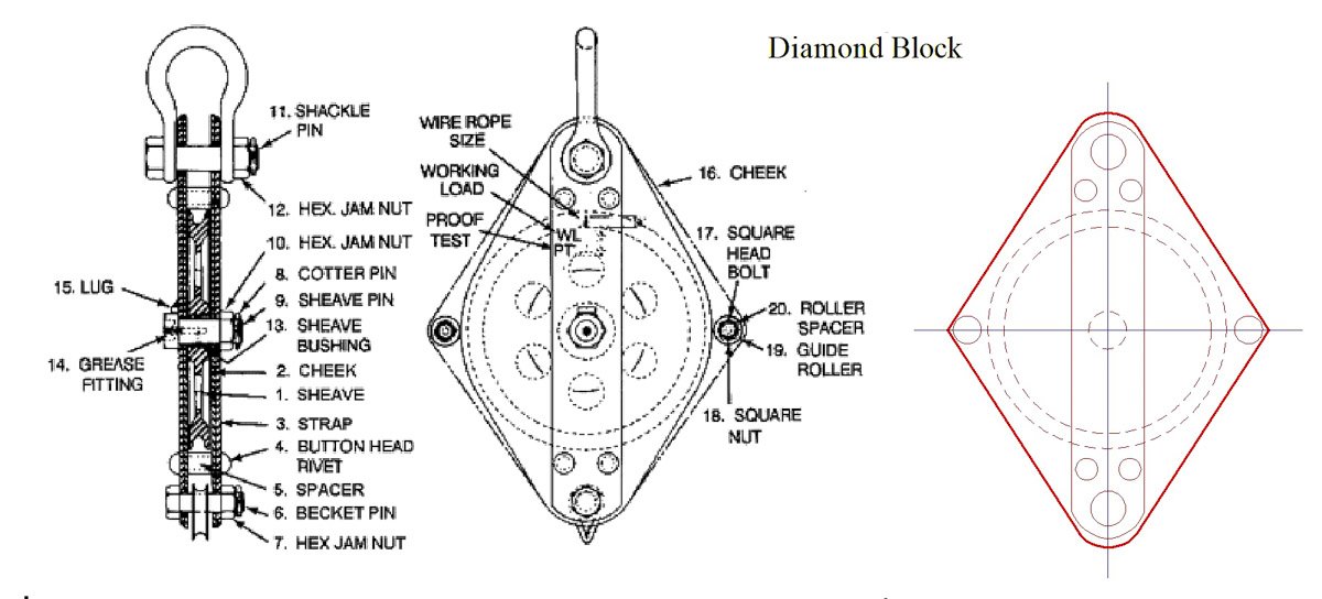
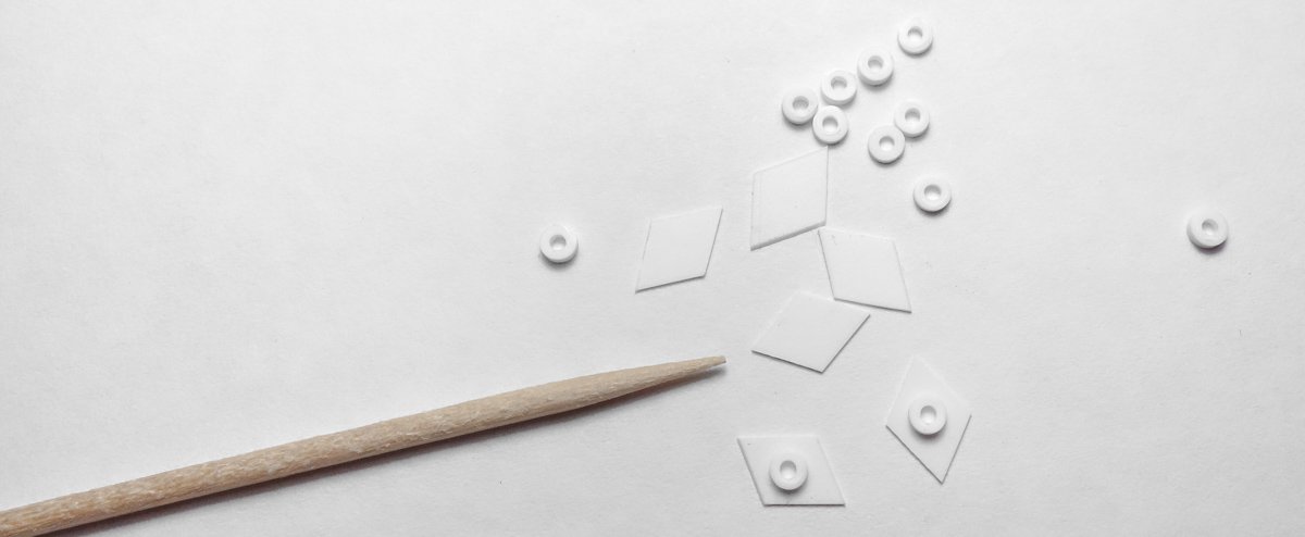
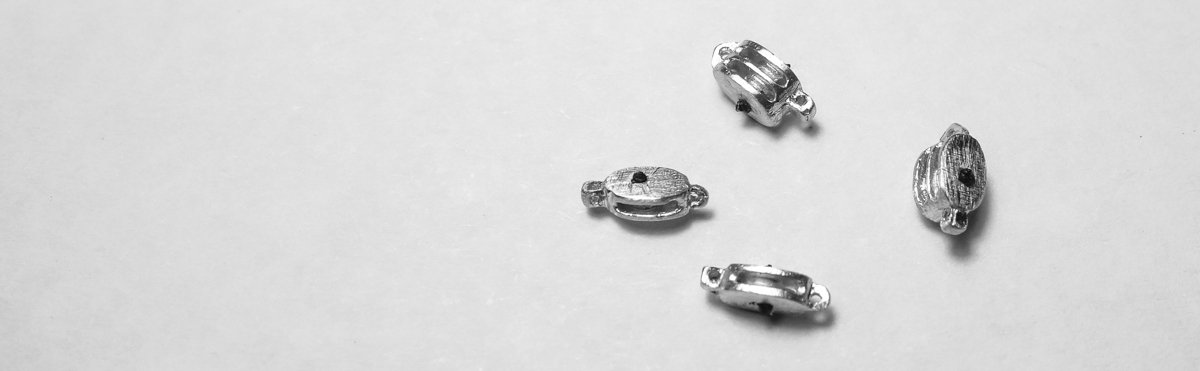
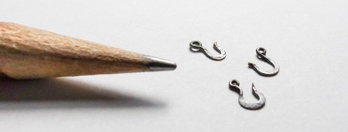
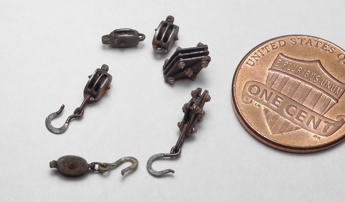
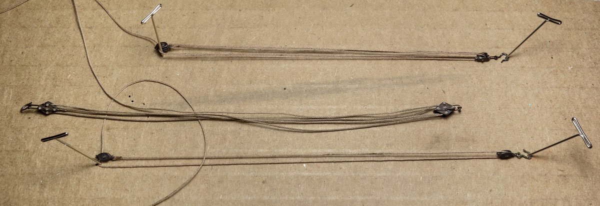
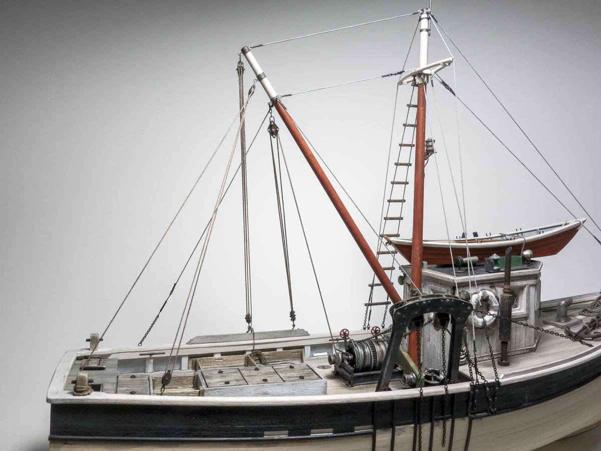
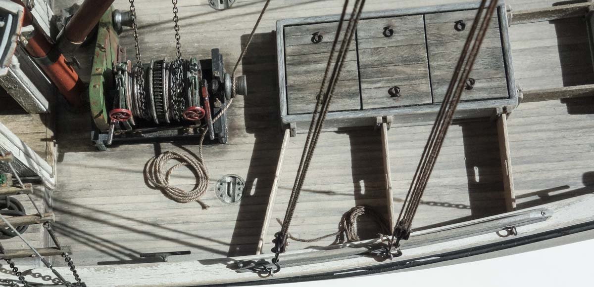
Roger: Thanks for the comment and your suggestions on the anchor. I believe they would have used the winch heads if the anchors were in fact heavy enough to justify it. After all, it's right there. I've already made some changes to the anchor that I describe in this post, so I'm going to let that settle before deciding on any other action. Tom: I hope it's artist block and not blockhead. But I agree, sometimes you just need to stay away for a time. Thanks for the reassurance Tom. And thanks to all for the likes. Anchor re-do and Blocks In my last post I stated I wasn't happy with the way the anchor looked on the deck and couldn't put my finger on why. I received a number of excellent ideas on how the overall look might be improved and I thank everyone for their valued input. I'm going to start with what I think is the most glaring problem first. Druxey rightly pointed out that the ball on the end of the stock was too large and only needed to be large enough to keep from slipping through the shank. Agreeing with that assessment, I reduced the ball size and also replaced the original stock with one that is tapered from its greatest diameter at the midpoint and reducing down towards both ends. The anchor is now more delicate looking (if such a phrase can be used to describe an iron anchor) and the overall look is improved albeit subtle – good spot Druxey. In addition, I also replaced the pipe anchor chocks with lower profile wooden ones. This positions the anchor down closer to the deck and the painted wood chocks ease the transition from black anchor to gray deck. I may return to the other suggestions made after I let the current changes simmer for awhile. An interesting detail that I've seen on a number of these draggers is the use of diamond shaped blocks to hoist the heavy cod-end of the net. Diamond blocks were designed for use with wire rope and have a larger radius pulley. They are being used here with textile rope presumably to take advantage of that larger radius. These blocks are smaller than the beefy tow blocks that were suspended from the boom/mast on boats that didn't use a gallows frame. Here is a drawing of how they are constructed. Styrene bits are cut. And two blocks are made. There are three hoisting locations and for the other two I'm using smaller blocks that I purchased from Bluejacket Shipcrafters. These blocks scale to about 8” tall and at just under 3/16” these blocks are nicer than I can make or have the inclination to try. So I cleaned up the parting lines and added injection molded bolt heads for the pulley shafts. Next I made up some hooks from .02” phosphor bronze wire. The bronze wire is pretty tough stuff and holds up to my bending and re-bending. Flattening the lower arc of the hook mimics the cast-in gusset of the real thing. Everything gets black enamel, pigments and graphite. I threaded the blocks with miniature rope - about 5/8” for the smaller blocks and 1” for the diamond blocks. The diamond blocks are arranged in “luff tackle”, the smaller double blocks in “two fold purchase” and the single blocks in “gun tackle”. I don't know and won't pretend to know how the fisherman went about the business of fishing and how they used these hoists. The boats didn't have identical hoisting and rigging arrangements and so I decided to place on my model merely examples of the many types of hoisting gear that I've see in old photos whether their location on the model is practical or not. But it seems the third hoisting location down from the end of the boom always carried the heaviest gear and it was from this gear that the heavy cod-end of the net was hoisted. This makes sense to me because structurally this is the strongest point on the boom. And I have seen in photos where the gear at the end of the boom is being used to swing containers of catch onto the dock. The rope tails of each hoist are coiled and placed on the deck. Actually, each coil is a separate piece that was wound on the workbench, glued together and then placed on the model to look as though they are the tail ends of the hoist rope. I did this because the rope is rather stiff and naturally wants to straighten, so the coils constantly spring open. But that really is a moot point because there isn't enough finger room to coil them in situ anyway. In this image, you can see two of the traveling blocks hooked to eye bolts positioned along the short rail. I also added several industrial looking cleats that I soldered up from brass wire. As I'm posting this, I notice in the photo above that the rope at the winch head is wound in the wrong direction. I may go in and change that if it starts to annoy me, but I've already snapped and tore off stays, eyes and chainplates with my thick fingered Shrek-like hands – so probably not. I take my hat off to you builders of multi-masted ships with all those delicate spars and endless rigging. I find even this small amount of string work to be challenging. A couple more photos. Thanks for looking in. Gary


- 424 replies
-
- 32
-
-
Roter Löwe 1597 by Ondras71
FriedClams replied to Ondras71's topic in - Build logs for subjects built 1501 - 1750
Just caught up on your build log from the beginning Ondras and your model is fantastic. Excellent clean and precise workmanship. Beautiful! Will be watching for future updates. Gary -
Masterful work Valeriy! Everything fitting into place perfectly - so clean and precise. Who knew a utilitarian metal stairway could also be an item of beauty? Remarkable craftsmanship and the silver plating is an elegant touch. Gary
-
Nice progress on the Providence Ken. Excellent work on the pumps and I really like the lantern - it has great proportions, coloration and is nicely made. Gary
- 238 replies
-
- 3
-
-
- sloop
- providence
- (and 1 more)
-
Good to see an update on the Tennessee Keith. Interesting historical/technical information on the Dahlgrens and a great start on their construction. And congratulations on the arrival of your new crew member. Emma is a cutie, but looking a bit mischievous. I’m sure she’ll be happy to help with the rigging. Gary
-
Here is a photo of a more recent boat. It's difficult to tell how large the anchor is from this angle, but it doesn't look that heavy - does it? My weight estimate could be way off. Gary

-
Hello everyone and thanks for the comments, suggestions and moral support. It is great to have the fresh eyes and experience of fellow modelers. Hello Keith. Thanks for your wonderful comments. You're right about the visual impact thing. As I creep closer to the end of this build, I find myself becoming more critical of my modeling. It's so easy to rush to the finish line only to trip and fall over your own shoelaces before you get there. I'm at the point in this model where I'm trying not to add anything that negatively impacts the whole. Thanks again. You are correct Druxey – the stock ball is too large. It is amazing how many times I looked right at it and never saw it, Good catch and thank you – I will be changing it. Wefalck, Chris and Eric - thanks for your observations and suggestions. Yes, the area around the anchor needs some tough love to pull it together and to look as though it has been used a few times. I'm going to take some time to consider exactly what to do, because if I hose up the deck, it's going to be a bear to fix. Thank you for your helpful input. That's easy – just pick it up one handed and throw it over your shoulder. In my dreams I can do stuff like that, but seriously - I agree, that is a chunk of iron. I wondered about this myself and it's hard to envision two men pulling up an anchor that weighs 140 lbs. standing on a pitching deck with no rail. Maybe they weren't as heavy as that and two men could easily handle it – I don't know. Something I have noticed, and it may be just coincidental, is that the anchors were typically stowed on the starboard side of the forward deck, the same side as the gallows frame. Obviously they would never be dragging a net and dropping an anchor at the same time, so I wonder if they utilized the winch or one of the gypsy heads to pull up the anchor. Once on board two men could easily carry it the 15 feet to its stow point on the forward deck, out of the way of the business of fishing. Thinking out-loud. And my guess is they didn't drop anchor very often. Good observation and thanks for the comment. Thank you Ekis Thank you Valeriy _ your nice comment is much appreciated. Gary
-
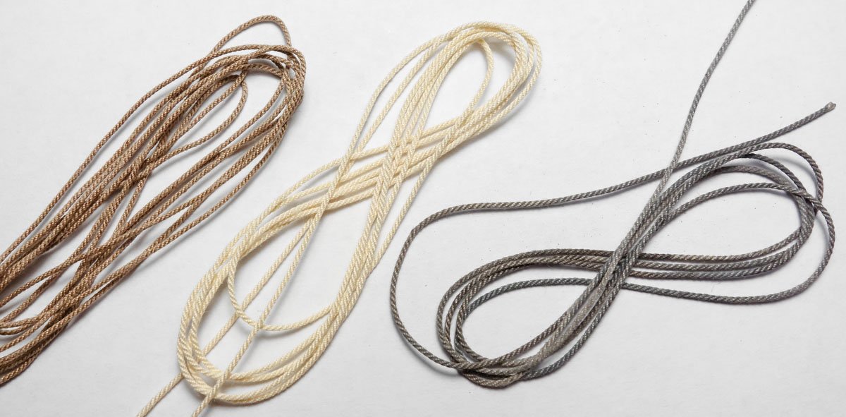
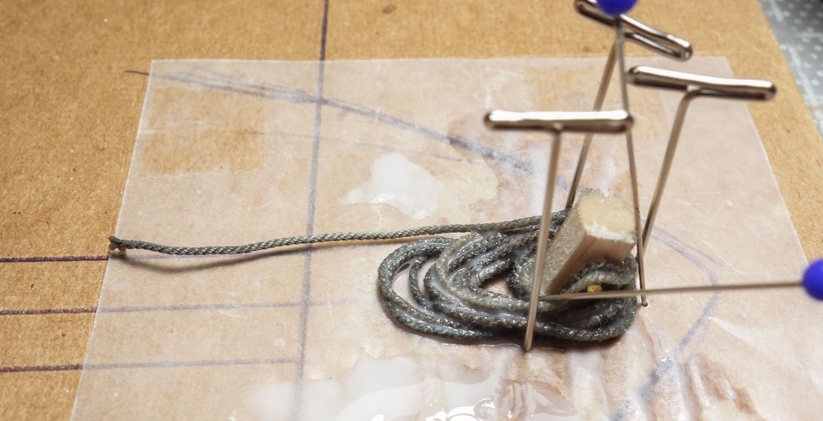
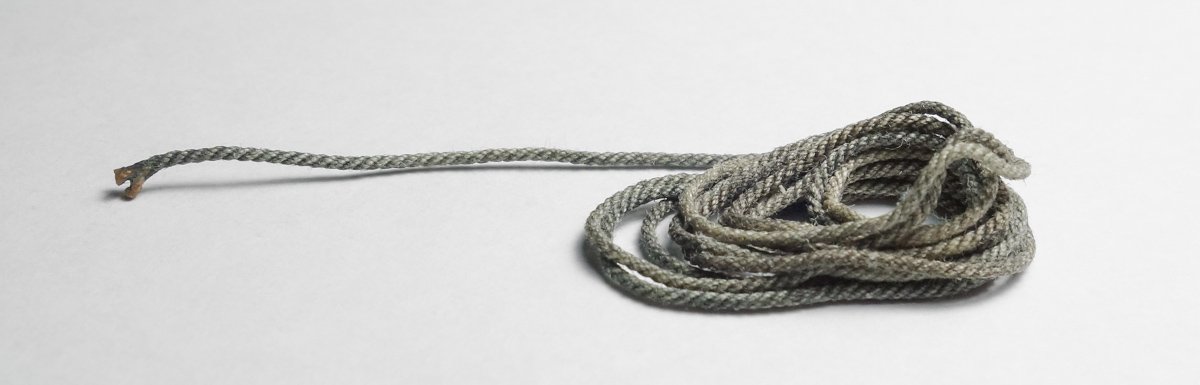
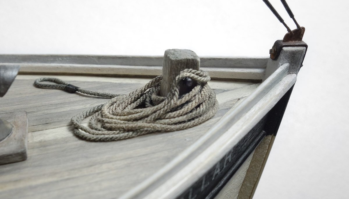
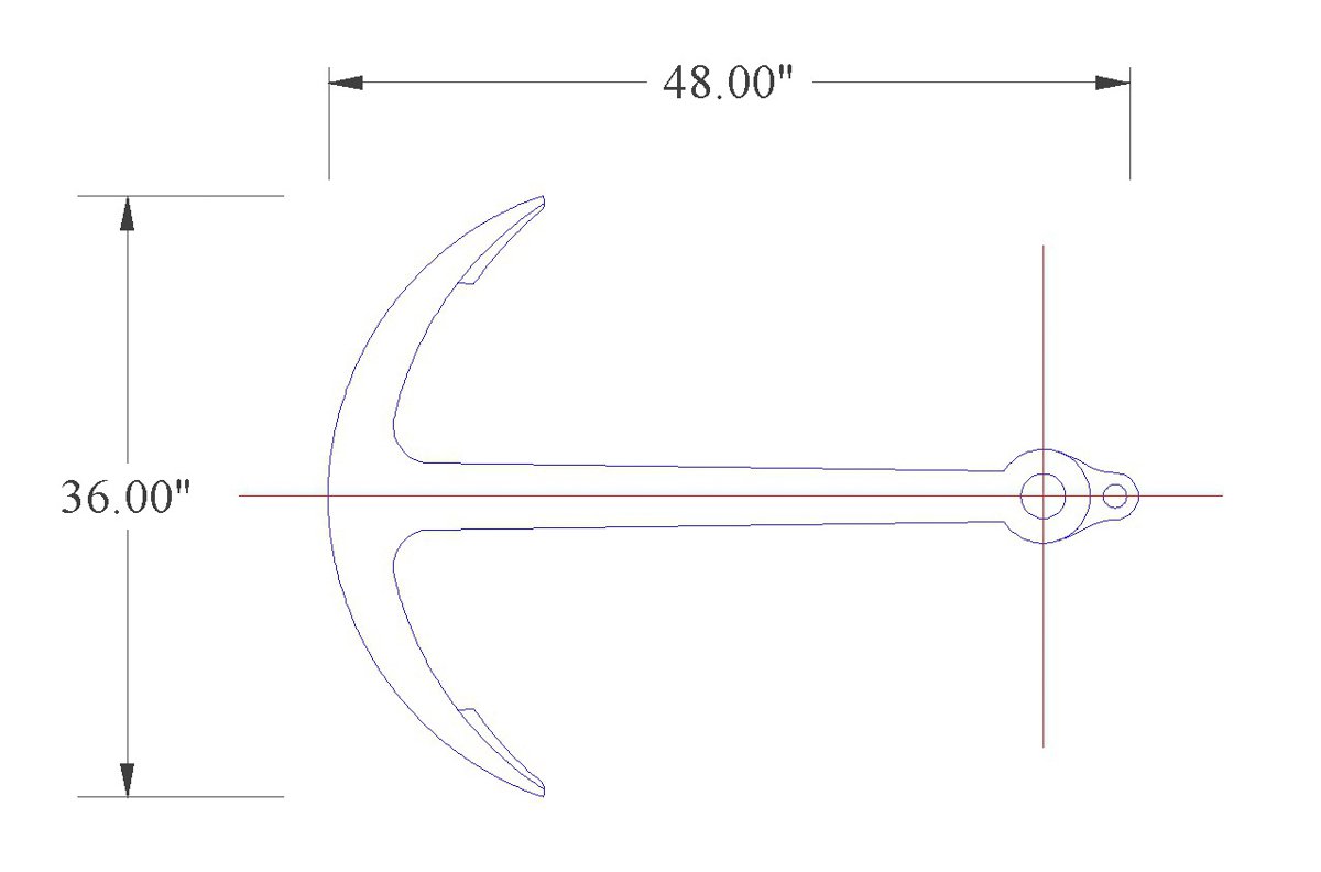
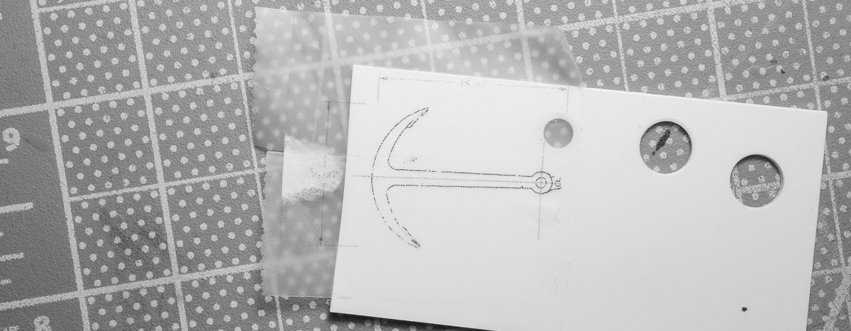
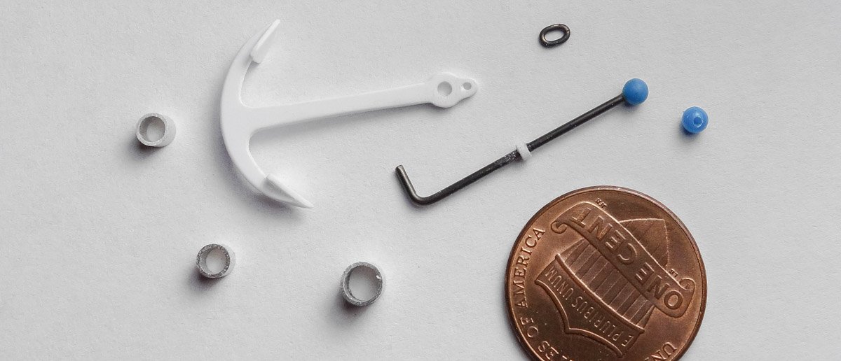
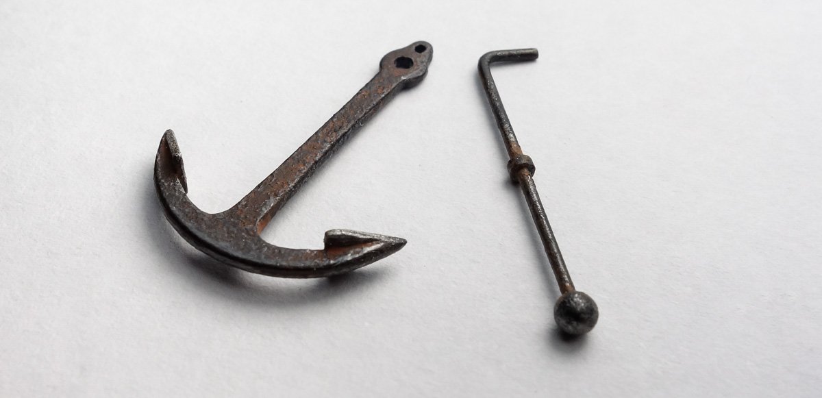
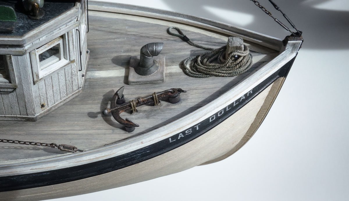
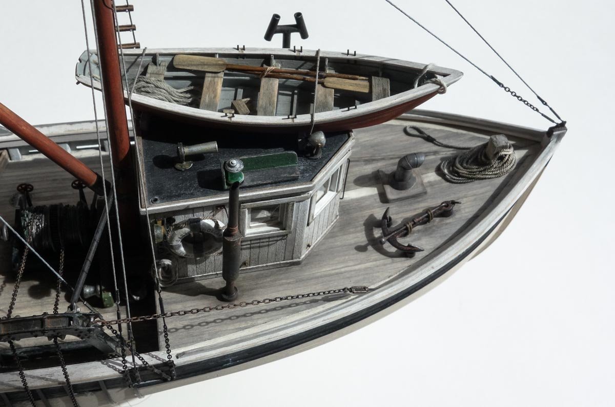
Thank you so much Druxey and Keith for the fine comments and your continuing support. It is greatly appreciated. And thanks to all for the likes and looking in. Welcome and thanks for checking out my build and the kind words. Thanks - I always wanted to be a cover girl. Some Rope and an Anchor The bitt on the fore deck needs some rope wrapped around it. I'm using miniature rope that scales to around 1-1/8” in diameter. The rope has a nice light brown color, but it looks too clean and new for this old boat, so I bleached it back to natural then added color of my own. I want something more salty gray and sun bleached. I use dry chalk liquefied with alcohol and then applied with a brush. I randomly apply three different colors to give it some variation. Where it's too heavy and dark or needs additional blending, I liberally brush on straight clean alcohol. This color and weathering business requires a lot of trial and error because often what looks great on the work bench looks ludicrous when placed on the model. Color and texture read differently based on what surrounds it. So after too gray, too brown, too dark, too light, I finally surrendered to the color shown below. The image shows the progression of original, bleached and final. I saturate the rope with a wet-water and PVA mix and arrange it on a mock-up. Enough PVA was added so it holds its shape, but no so much that it can't be pulled apart and straightened. I then worked it over the bitt and any coils that didn't lay flat were glued down. Looking through photos for an anchor type, I was surprised by how few of them I actually saw on the boats. When I did see one, they were commonly the Danforth type. But those weren't invented until 1939 and this model predates that, so I can't use one of those. I did see folding stock/admiralty anchors on a few boats and I guess a couple of fit men could pull a small one back up by hand when needed. No windlass on these boats. Below is the anchor I'm making. I traced an internet photo in CAD and scaled it down to an appropriate size. This would weight in the 110 to 140 lbs. range depending on the source of info.. The drawing is printed on cellophane tape and affixed to styrene. It is cut out large and filed back to the outline. Flukes are cut, glued on and filed. The stock is blackened phosphor bronze and the balls are dressmaker pin heads. The chocks are slices of aluminum tube. Everything was painted flat black enamel and poked at with the end of a firm brush to achieve a rough textured surface. (I let the paint firm up a bit before I start to poke at it – a cosmetic sponge also works great.) Once completely dry, a rust colored pigment is washed on and quickly wiped off with a finger leaving color down in the recesses. I used pigment and alcohol here, but thinned acrylic or other color wash works just as well. Finally, pencil graphite is rubbed on where I want to show seafloor abrasion. Glued to the boat along with some hold-downs. I'm not really sure what it is, but I'm not happy with how these two items look on the boat and I haven't determined what needs to be done to fix it. Something just doesn't look right and it bugs me every time I look at it. For now I'll just give it some time to stew. Any and all observations and criticisms are always welcomed. Thanks for stopping in. Stay well. Gary
- 424 replies
-
- 18
-
-
And it shows! Your model displays more than the craftsmanship of its construction, it also displays the pride you have in the work. Wonderful progress Valeriy - keep it coming. Gary
-
Fantastic work on the boiler Brian! I like your technique on the rivets and the dry-brushing highlights them nicely. Wonderful result. Gary
-
Sorry to hear of the passing of your old friend Keith. Pets certainly are members of the family and it’s difficult when they pass. Naming your restoration ship after her is nice. Gary
-
I think we all have experienced frustrating days in modeling. I know I certainly have and when I do, I simply drop everything and walk away grumbling before I make matters worse. Good progress Vaddoc and the frames/bulkheads look great. Gary
-
I've been following along on your build Brian, and for a first-time scratch builder you're remarkably attentive to accuracy and the workmanship is clean and careful. And you've picked a great subject. I've always been somewhat of a "Western Theater" Civil War buff and I find this period of U.S. history endlessly interesting. A great start on an interesting and unique model. I realize that you have decided to go with printed paper for the brick work, but for future reference, there is a company called New England Brownstone that manufactures Hydrocal brick wall slabs in 1:48 and 1:87. They are made in the American bond pattern with tie header courses. You have to color the slabs yourself (they tell you how) and it is not a cheap product, but with careful execution they produce the most realistic brick work in those scales that I have seen. Looking forward to future updates. Gary