

bruce d
-
Posts
2,969 -
Joined
-
Last visited
Content Type
Profiles
Forums
Gallery
Events
Posts posted by bruce d
-
-
FM, good advice (as usual) from Allan, and another book by Philip Reed is close to your stated needs:
PERIOD SHIP MODELMAKING An Illustrated Masterclass
It's on Ebay, AbeBooks and other places as well. In iit he walks us through building Prince de Neufchatel in 1/192 scale.
McNarry and his wife were superb modelmakers and won quite a few pots at early Model Engineer Exhibitions in London.
HTH,
Bruce
- Ferrus Manus, druxey and allanyed
-
 3
3
-
-
What Allan said, plus check the lines with a straightedge and measure the diagonals (corner to corner) for skew.
- thibaultron, mtaylor, allanyed and 2 others
-
5
-
Hello Paul and welcome to MSW from the UK.
- mtaylor and Keith Black
-
2
-
Update: AL have just announced a whole new Santisma Trinidad:
Also, JoTika are promising a 74 with an interesting history. My bet is it will be HMS Defiance, a Trafalgar veteran, but we will have to wait and see.
- Kingspoke, Artesania Latina, Canute and 2 others
-
5
-
-
-
Fascinating.
My only potential contribution is to look at the word FULMINANT when translated into English. The modern translations all steer us to 'angry', 'furious' or 'quick like lightning' but the older translations included 'splendid'.
The magnificent drawings have a theme of bundled lightning and flaming spheres. They follow military decorations and emblems of grenadiers of the period so closely that it cannot be a co-incidence. These decorations would have suited a bomb vessel.
-
-
Kevin, just watched your newest video online. Nice work, enjoy your break.
- mtaylor, billocrates and Kevin Kenny
-
3
-
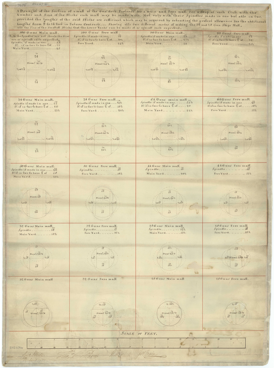
These drawings from the Danish archives may be of help.
D206 is for English ships '80 and 100 guns', undated but from late 18th century:
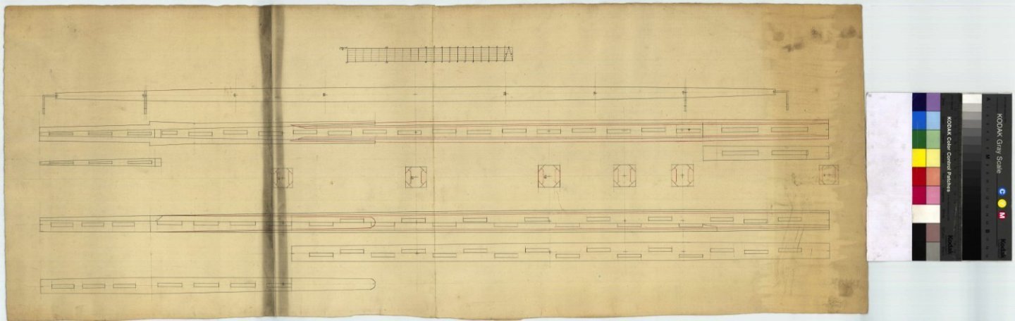
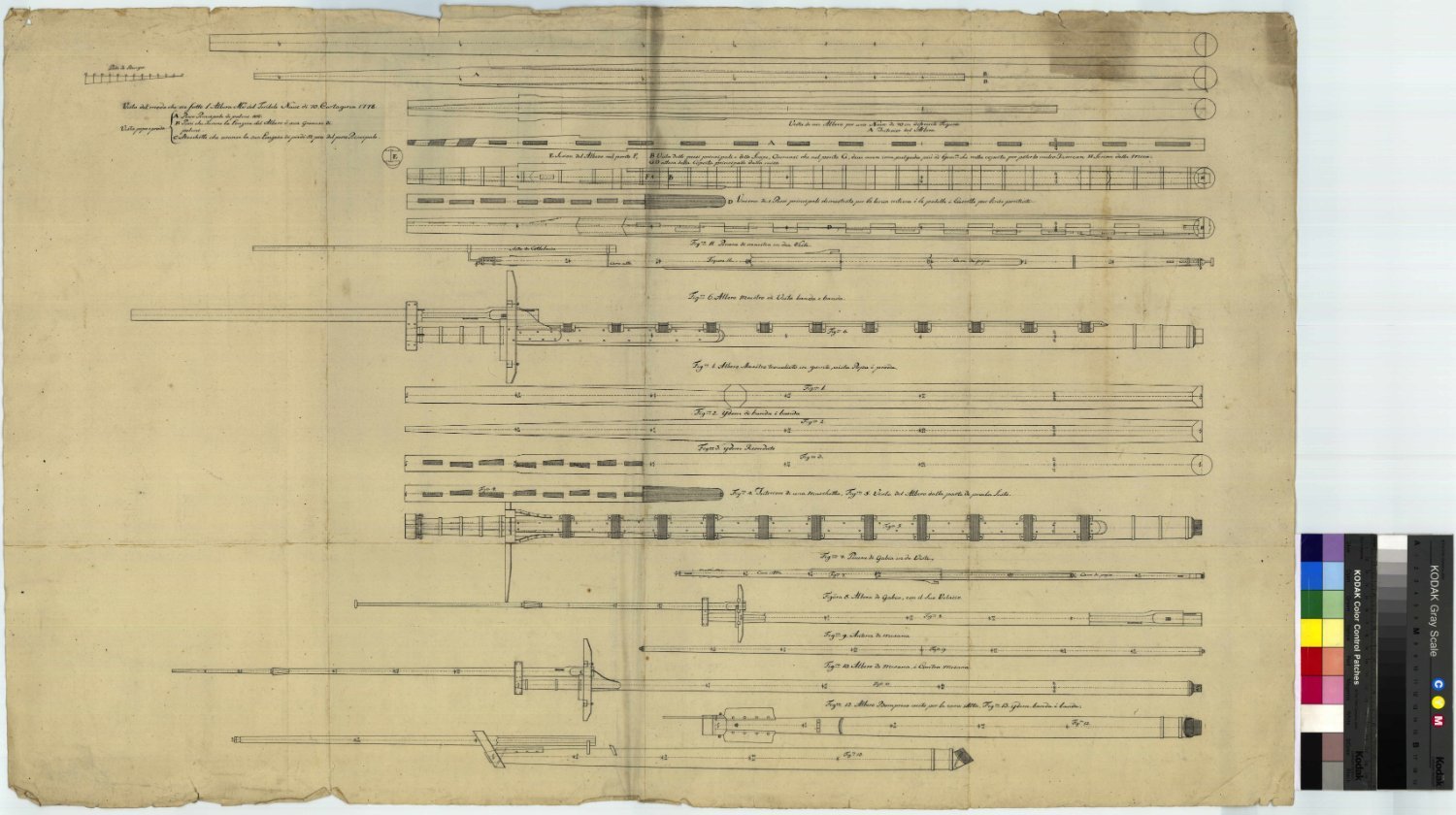
D201, as above but for 74 gun ships:

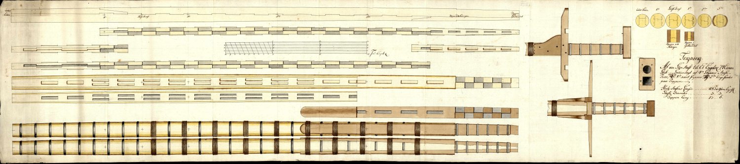
G4728, more 74 gun ship masts:
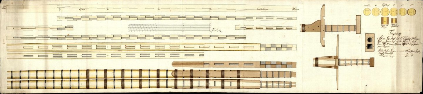
You can download hi-res copies free from their website:
HTH
Bruce
-
Lovely model, Richard, and I like her just the way she is.
- Knocklouder, AJohnson and Richard44
-
3
-
-
Fantastic job, Ken, and what a great subject.
I was lucky enough to see this beast run. Tommy sold it to a guy (name long forgotten) who put a Buick station wagon body on and VIOLA! - instant funny car. It was a crowd pleaser. I have some 8mm film of it somewhere, now that you have reminded me.
Again, good job.
👍
- xken, Jack12477, Haliburton and 6 others
-
9
-
-
Update: I've remade a handful of frames and am plodding through the steps already described to get them into play. The next step requires all frames to be present and correct.
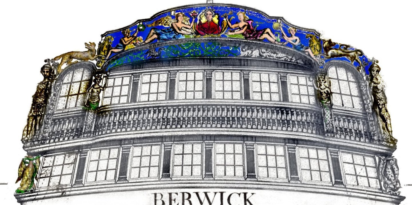
In the meantime, I had a very pleasant visit to Royal Museums Greenwich (a.k.a. The National Maritime Museum). The only plan of Berwick showing the stern decoration and figurehead, J2632, is not available online in hi-res and I am glad to say I was allowed to view the original. The detail is superb and, I confess, more elaborate than I had imagined. There was a 'what have I done?' moment but it passed.
For copyright compliance reasons I will not post the images taken directly from the original. However, I have begun a crude process of digitally separating the components and looking for clues as to what was carved and what was painted. It is based on J2632 but is modified enough to allow me to comfortably post it here.
This is work-in-progress, a tool to get me closer to the finished model and will evolve. Plan A at the moment is to start on the stern decoration as soon as the re-drawing is completed, the figurehead later.
-
-
11 hours ago, kurtvd19 said:
... anyone building a British warship of the late 18th century.
Kurt, I am sure this will be popular. Which edition is it please?
- thibaultron, mtaylor and allanyed
-
3
-
-
I wish I could find a book sale like this.
Well done.
- mtaylor, aaronc, thibaultron and 1 other
-
4
-
-
-
The advantage of using the adjustable stops is that I can make minute changes in seconds. This was useful when setting up but now it's locked.
I performed a couple more tests than are shown and my guess is that each frame will take about two minutes to slot.
Now I'm curious. Maybe a separate thread asking has anyone here used a dado on their Byrnes?
-
After a delay due to life-stuff, I am back in the fiddleyard.
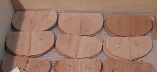
Having made the frame half-sections in pairs and fours (post #3) and then butt-jointed two together to make a complete frame (post #18), I did some quality checking.
A few assemblies failed inspection and were remade from spare stock. I made about 50% more than needed when milling the Swiss pear to cover the learning curve but, so far, I have only had to remake four frames. All pieces got a very light sanding, had their identifying marks freshened up after all that handling and checked one last time. Once satisfied, it was time to cut the slot in each that would locate it accurately where it belonged on the building board. As bdgiantman2 mentions above, this stage appears demanding. The slot in each frame piece must be dead centre and a good fit on the spine running centrally on the board; if not, any slop will show up later and cause headache and grief. Getting this right started with the fussy approach taken earlier to getting each of the half-frames aligned precisely in the assembly jig.
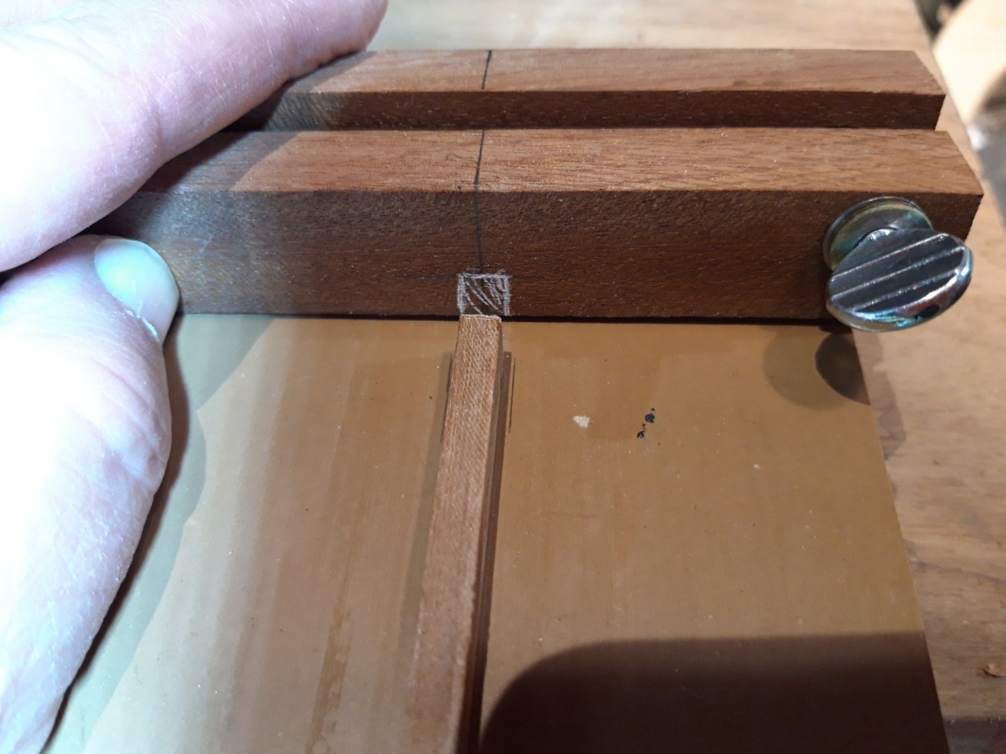
So, to business. The butt-jointed frames all have their centre-line at a perfect right angle to the straight line across the top, sort of visible in this photo:
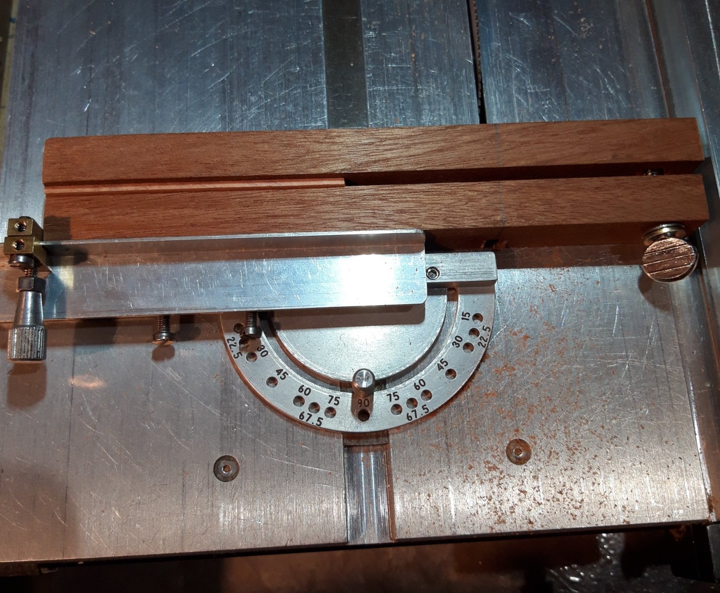
In order to put the slot consistently in the same place on all (50+) frames a jig and fixture were needed.
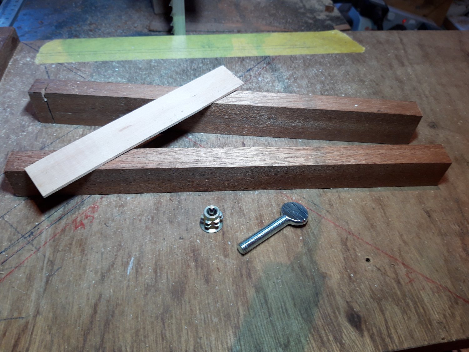
The fixture first. It consists of two pieces of hardwood, sapele I believe, planed smooth, square and parallel; an offcut of Swiss pear as a spacer the same thickness as the frames to be held; and a thumbscrew and M6 wood insert. A couple of woodscrews finished it off.

The pear was sandwiched between the two pieces of hardwood and then, after predrilling, two woodscrews pull them together.
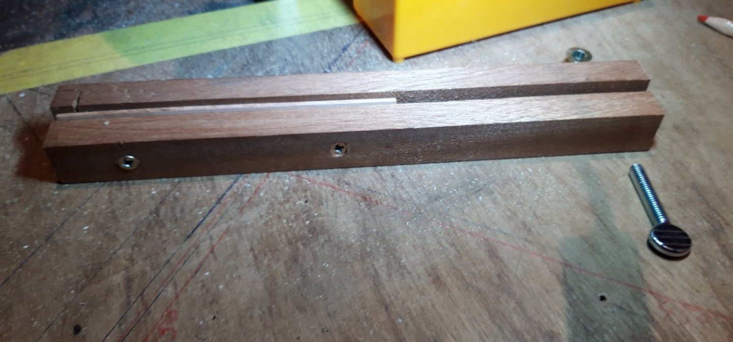
The assembly must sit flat without any rocking. I ran a plane along the bottom to make sure. In use, the threaded insert will be at the back on the right and the thumbscrew faces the operator.
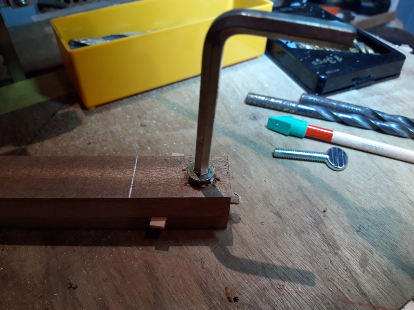
The gap between the pear spacer and the thumbscrew is large enough to accommodate the widest of Berwick’s frames. A line is permanently marked in this gap and a clearance slot on the bottom is scribed accurately on it.
This fixture, with a frame clamped in place, will slide right and left between two fixed stops. The saw is prepared by mounting my sexy auxiliary fence with a travel stop to limit travel to the left and the standard Byrnes fence to the right. Trial and error produced a good, snug fit.

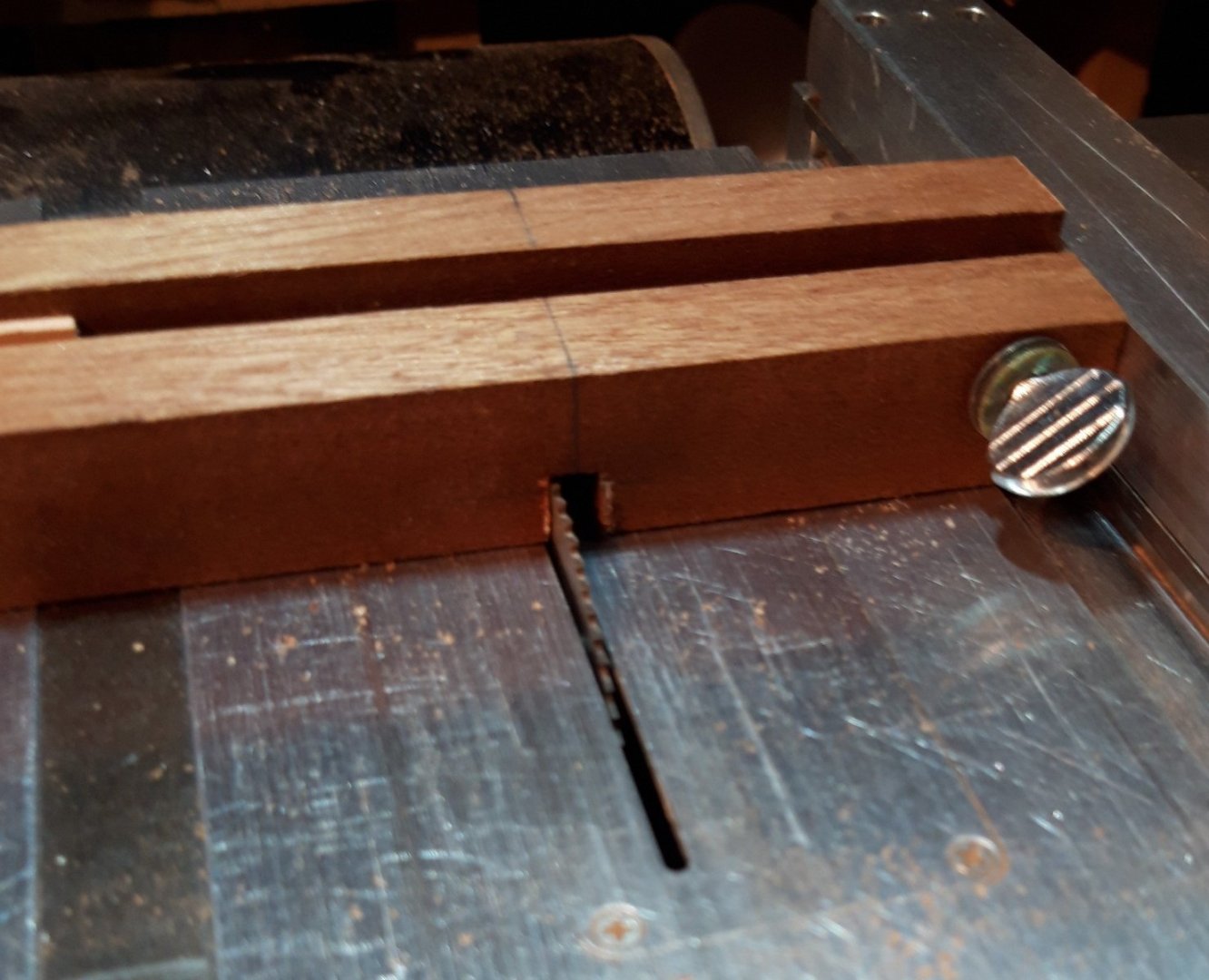
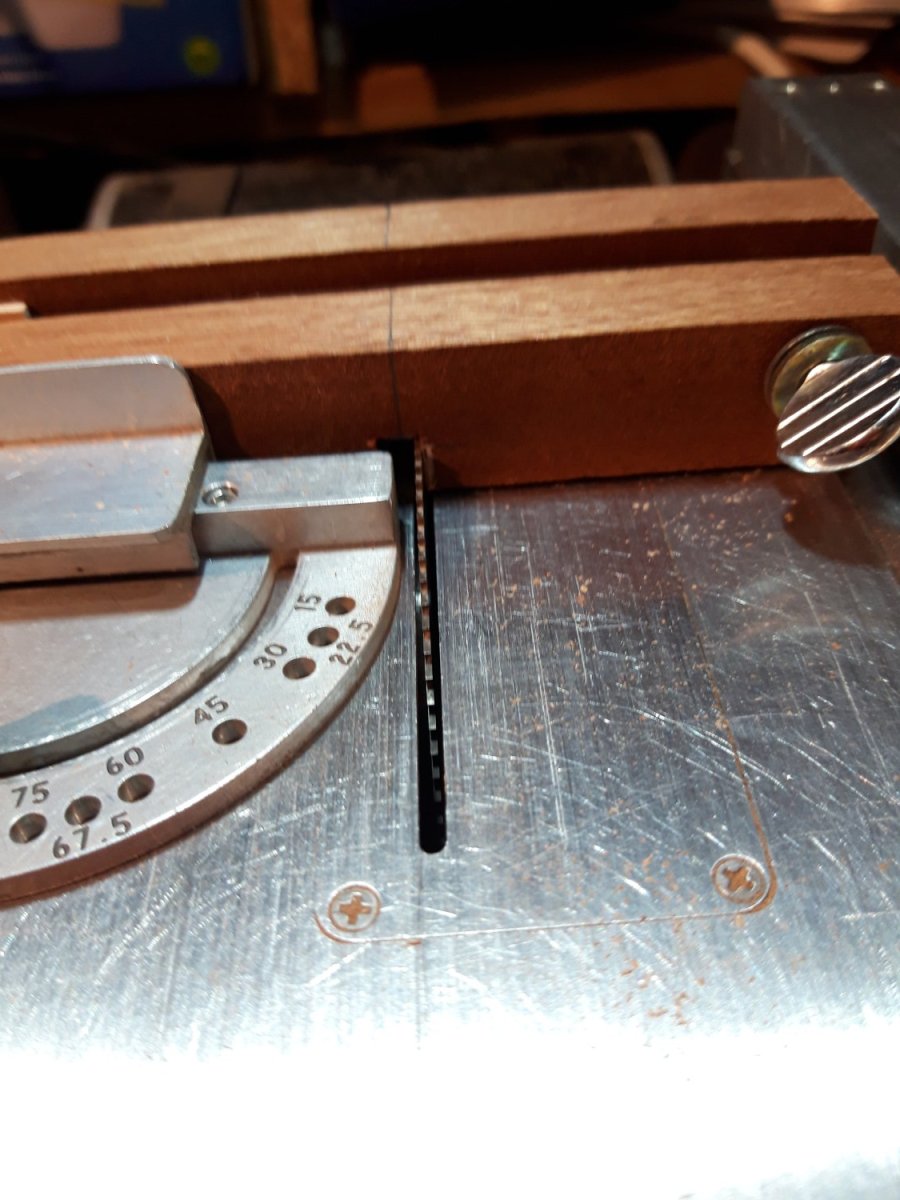
Cutting the slot, with the fixture at full travel to the right:
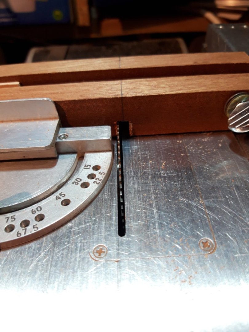
… and to the left:

The finished slot:
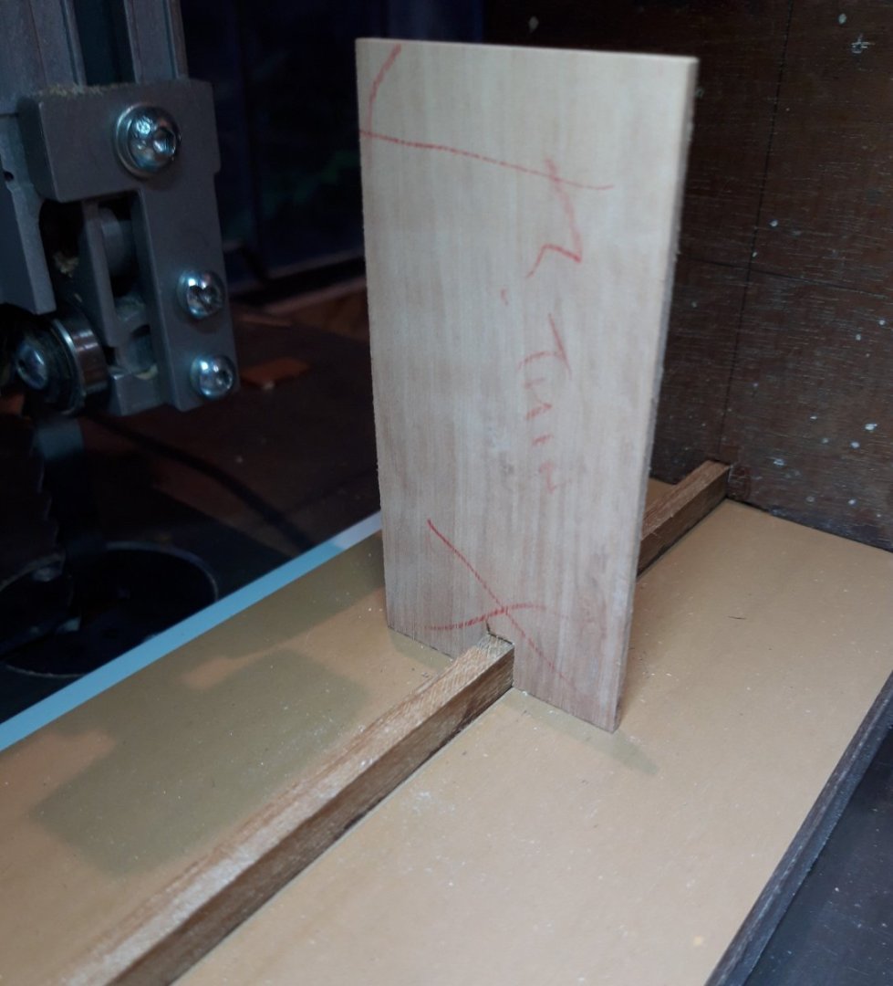
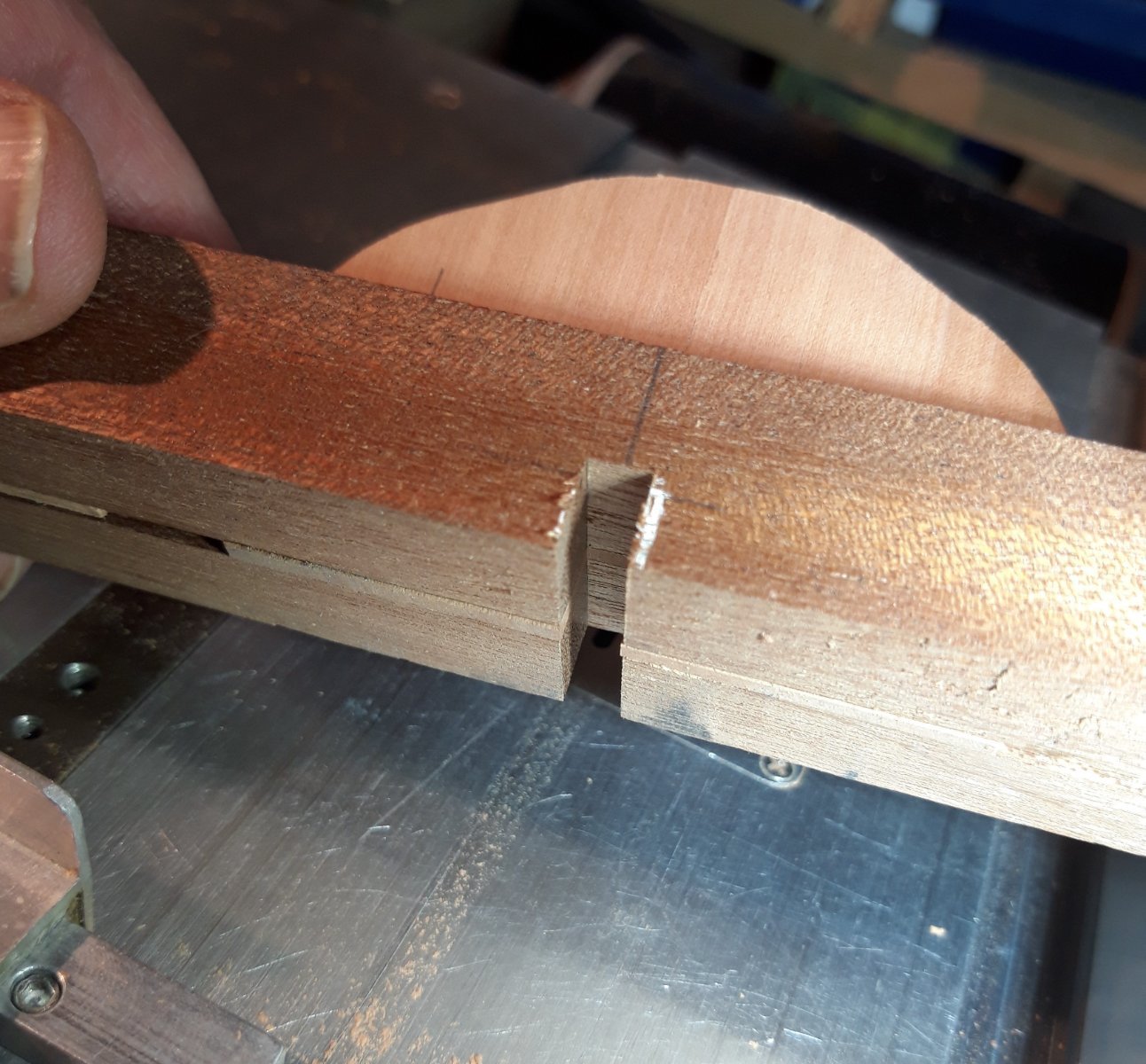
A test piece was aligned, clamped and passed back and forth over the blade. It worked well, the test piece fitted snugly on the spine:
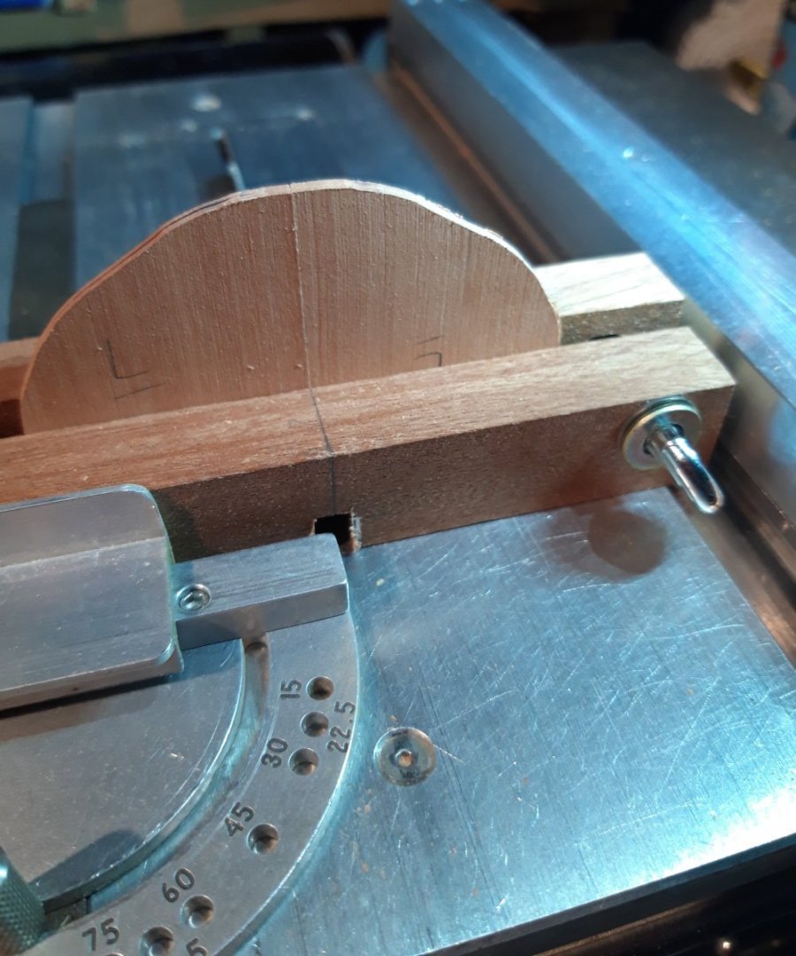
Time to try it for real. Profile ‘L’ is one of the wider profiles. Line up the centre-line, re-tighten the left and right stops and go.
Viewed from below after cutting but before removing the workpiece:

I am happy with the fit and, as long as I am careful lining up the joint on the profile assemblies and don’t touch the locking screws on the stops, they should all be consistent.
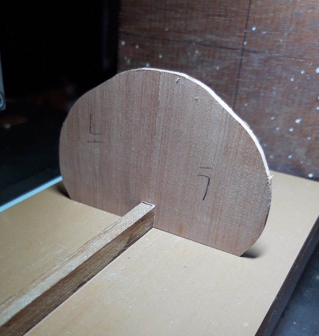
Fifty-three to go.
- GrandpaPhil, davyboy, mtaylor and 6 others
-
9


18-Pounder Pivot Gun
in CAD and 3D Modelling/Drafting Plans with Software
Posted
These may be of use:
Rijksmuseum
Rijksmuseum
HTH,
Bruce