tlevine
-
Posts
2,033 -
Joined
-
Last visited
Content Type
Profiles
Forums
Gallery
Events
Everything posted by tlevine
-
 Ian, I set up a jig similar to the one shown below. I nailed two brads into a scrap of 2x4 and wrapped the wire around them, leaving the ends along the straight part of the plate. I then used a needle-nose pliers to pinch the wire just inside the brads (dotted line). The ends of the wire were then trimmed and soldered using a silver solder paste. Some of the silver flowed along the straight part of the plate, securing everything. No drilling required.
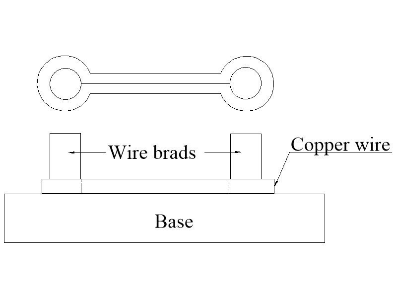
-
I purchased mine from Rio Grande but Amazon also has it in smaller quantities. https://www.riogrande.com/product/copper-square-wire-dead-soft/132410GP/?code=132423 https://smile.amazon.com/Gauge-Copper-Wire-Square-Dead/dp/B08K8177PZ/ref=sr_1_24?crid=1YGLS6ZFIR23C&keywords=copper+square+wire&qid=1656709809&sprefix=copper+squ%2Caps%2C347&sr=8-24
-
Thank you to everyone for the likes. I have made the rope for the gun rigging. Making the blocks comes next. Druxey, I started with sheet brass. Then I decided to clean my workroom, In doing so, I found the spool of square wire that I had used for the planking bolts. 24-gauge was the perfect size for the job. After a few "fails", the process went very quickly. I would never go back to the other way. After a Sparex soak, I used brass blackener instead of liver of sulfur and had no issues with blackening.
-
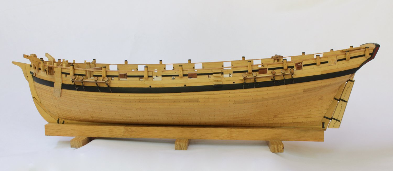
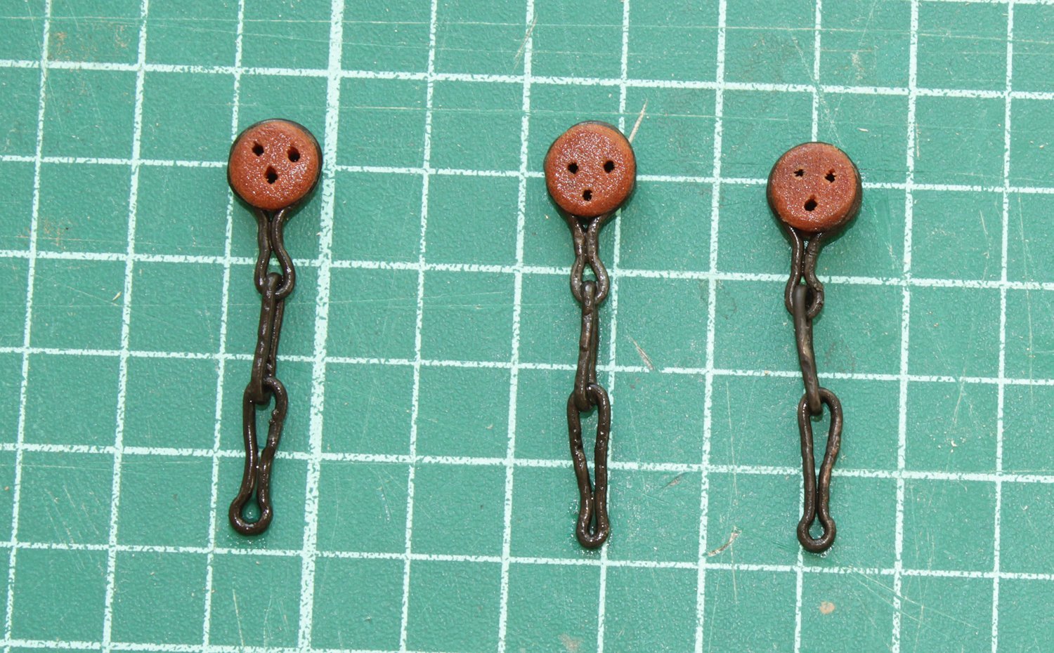
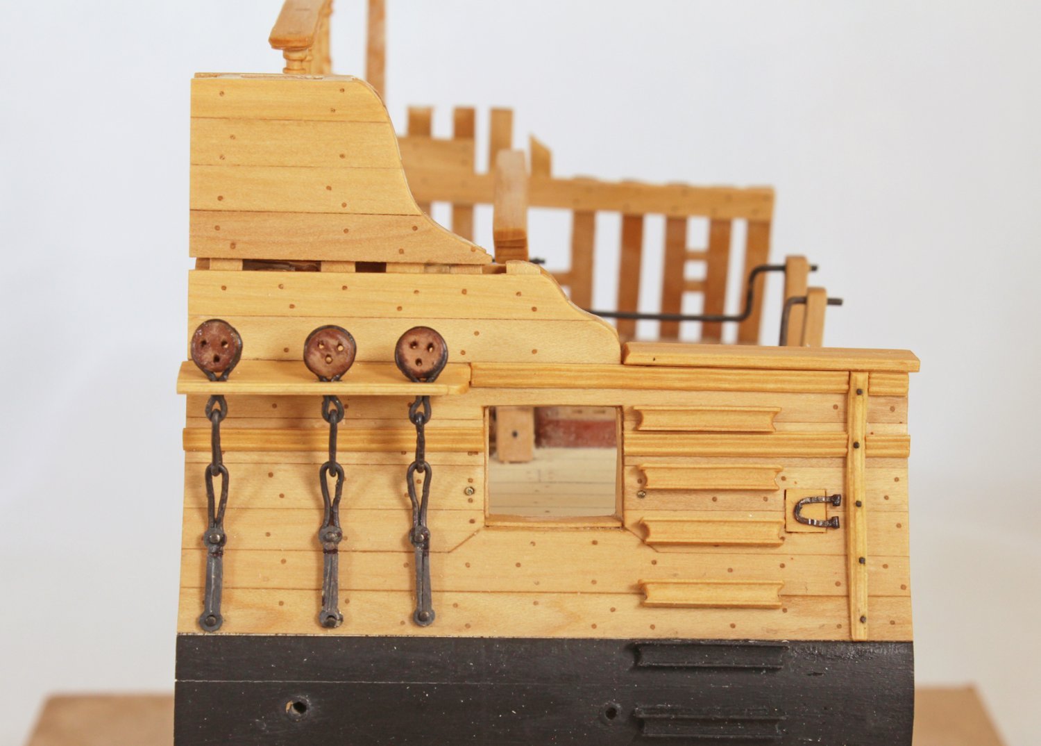
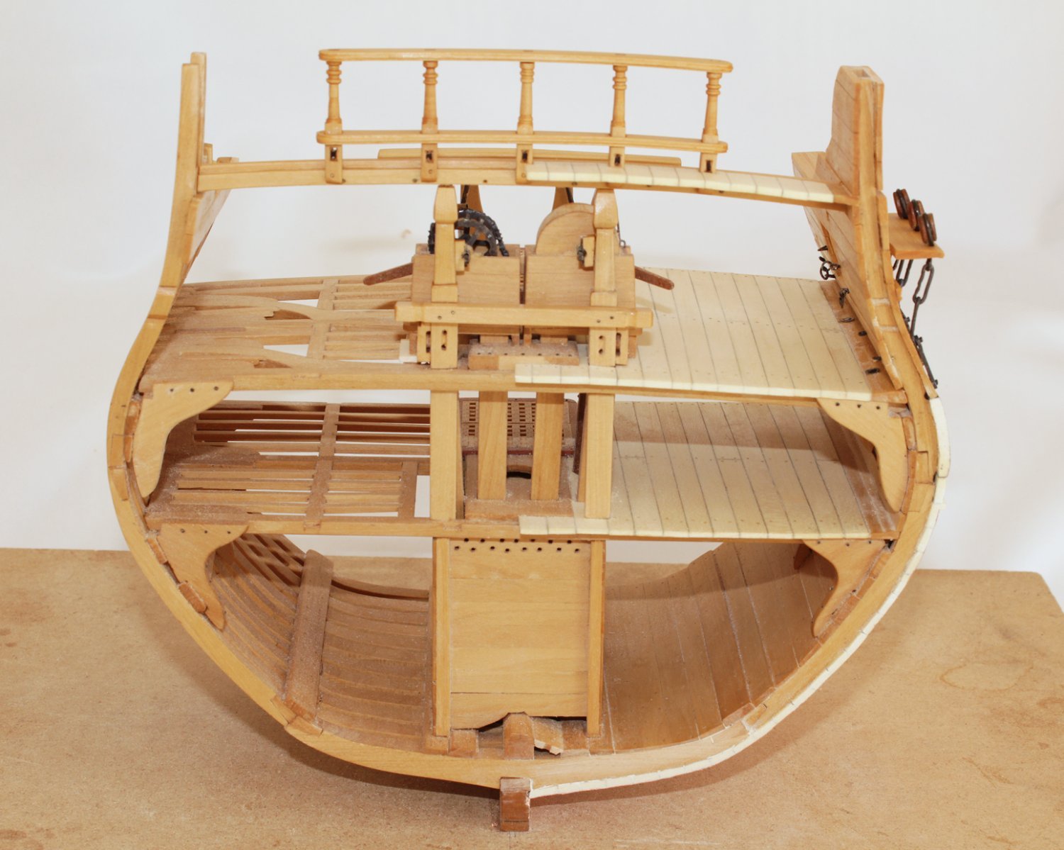
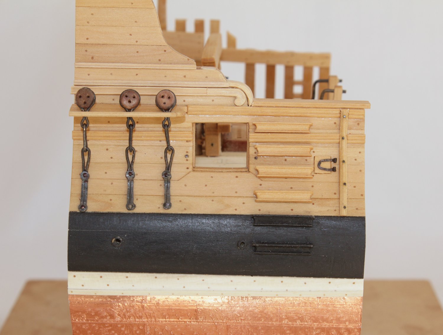
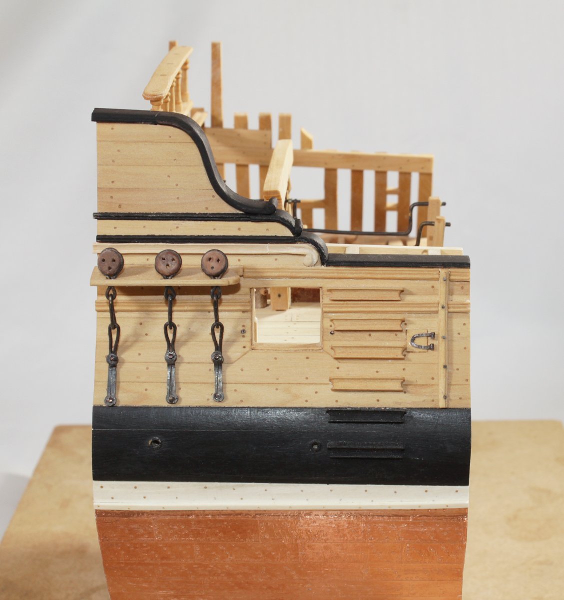
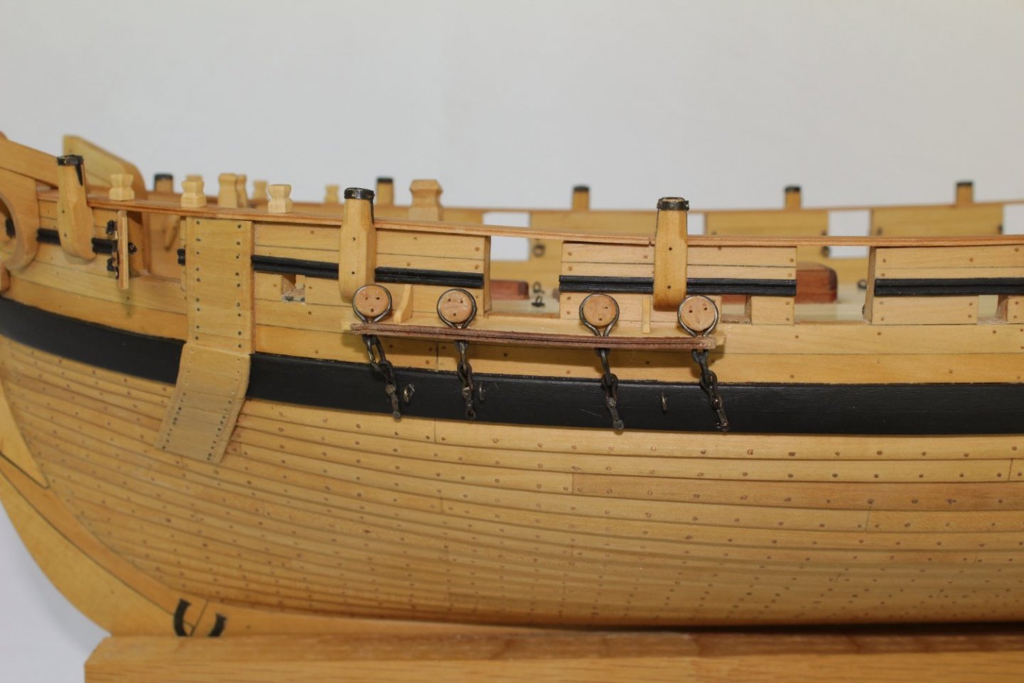
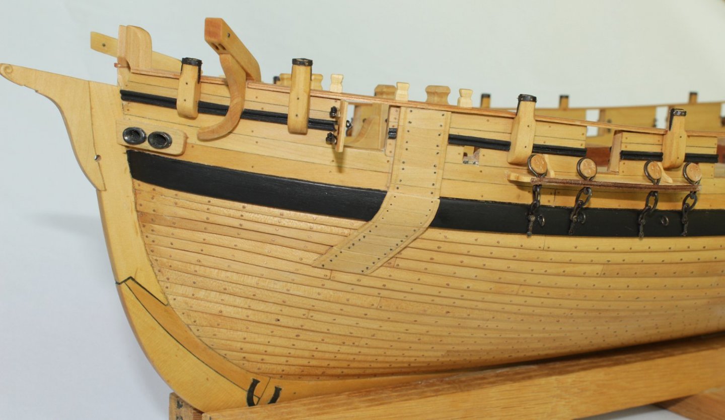
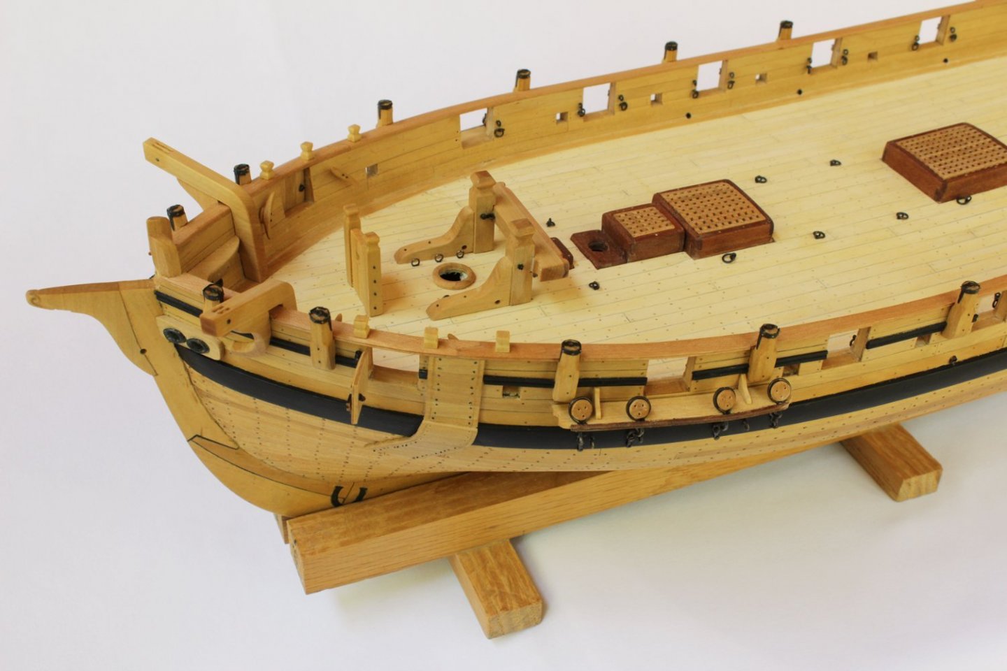
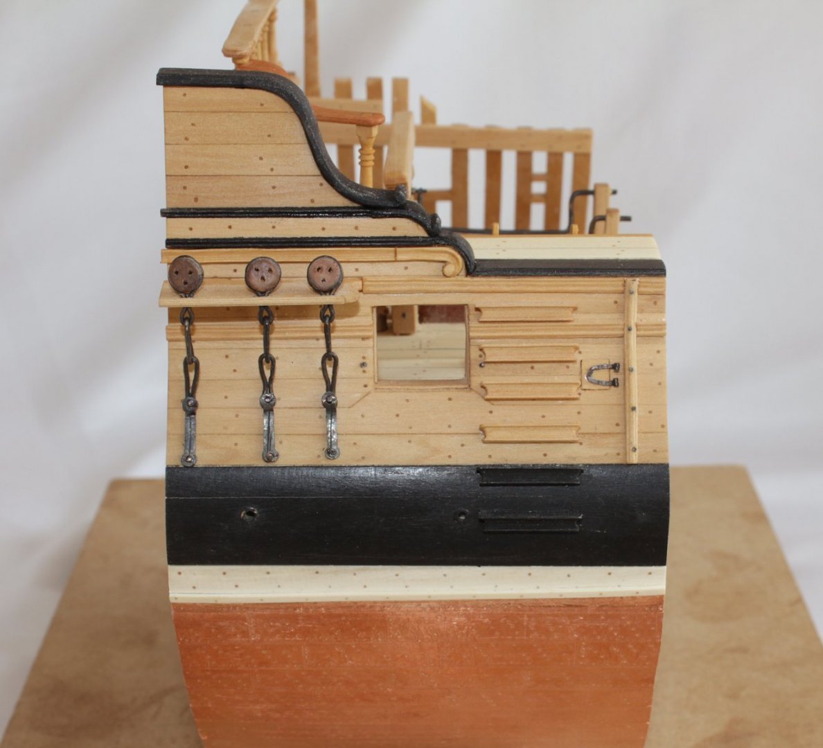
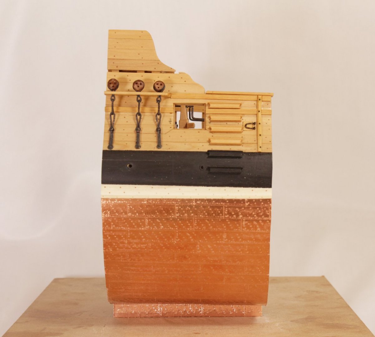
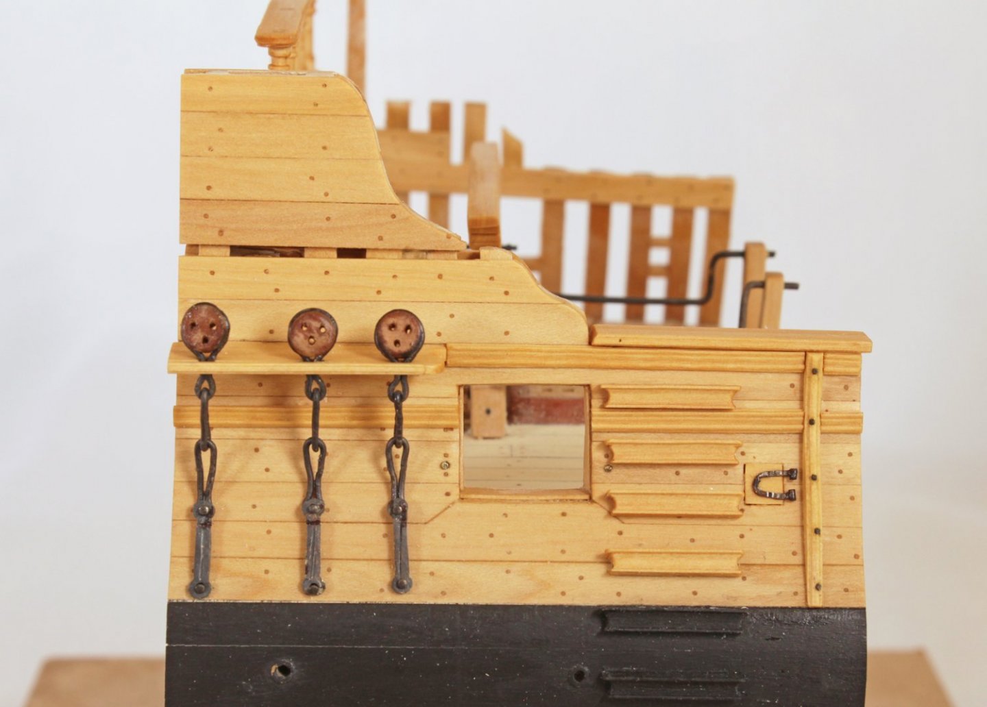
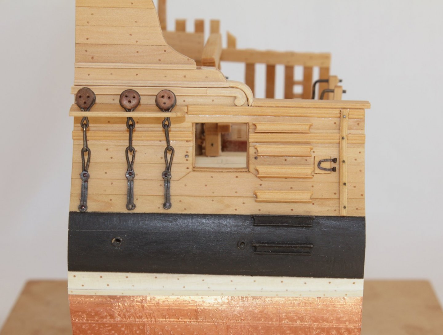
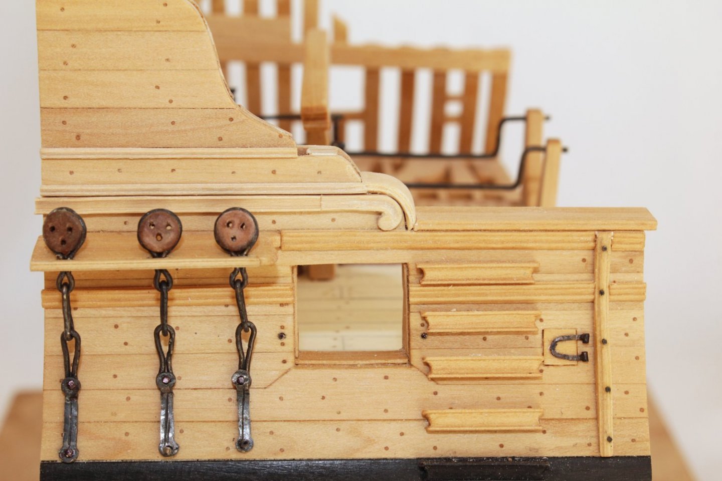
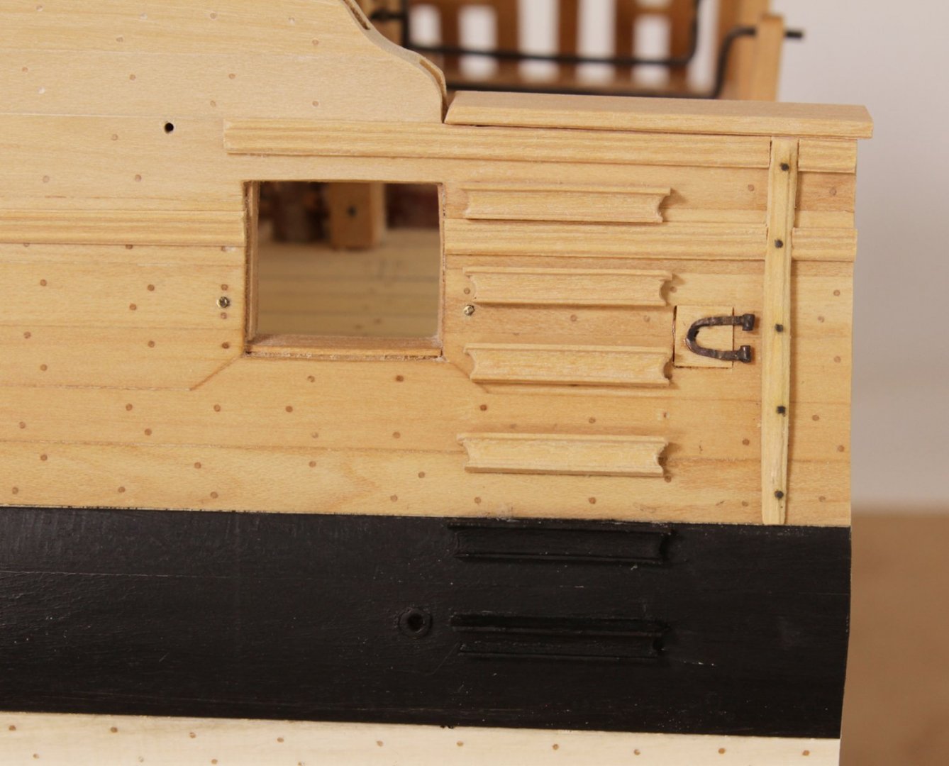
I realize it has been a long time since this build log has been updated. Between finishing the Echo cross-section and the garden, there has been very little time for her. I have finally made some progress. The channels, deadeyes and chainplates have been installed. The angles for the chainplates was determined by stepping a false lower mast and running a line from the top to the chains. The deadeyes are made from English boxwood. I have not decided whether I like the color contrast of the channel moldings. These were made from apple. I tried a different approach on the preventer plate. Previously, I would cut the plate from sheet brass, drill the holes and score the middle of the plate. This time, I used 24-gauge square copper wire. I set up a jig with two brads, wrapped the wire around the brads, pinching at their bases and silver soldered the ends and center sections together. Heating the plate during the soldering process had the benefit of softening the metal so it could be bent over the middle link. Other details have been added. Preventer eyebolts have been installed, as well as eyebolts along the two masts. Only the foremost port was fitted with a cover. This was fitted so it would hinge on its fore side. The contemporary model shows six exposed timberheads, five in the bow area and one aft. The plan only shows three in the bow and none aft. I followed the plan. Next up will be rigging the guns.


- 277 replies
-
- 37
-

-

-
NAIAD 1797 by Bitao - 1:60
tlevine replied to Bitao's topic in - Build logs for subjects built 1751 - 1800
I'm speechless. That is absolutely gorgeous.- 371 replies
-
- 10
-
-

-
NAIAD 1797 by Bitao - 1:60
tlevine replied to Bitao's topic in - Build logs for subjects built 1751 - 1800
I agree. Please show us more of the stove. -
That sums it up perfectly, Greg. If it were not for you and David, my model building would never have become what it is today. What you gentlemen create is the stuff we can only dream of achieving.
-
Looks great!
-
Thanks for the update, Ron. Love the breechings.
-
Echo by tlevine - FINISHED - Cross-Section
tlevine replied to tlevine's topic in - Build logs for subjects built 1751 - 1800
Thank you, Christian. -
Swan-Class Sloop by Stuglo - FINISHED - 1:48
tlevine replied to stuglo's topic in - Build logs for subjects built 1751 - 1800
Convolvulus sabatius Also known as African bindweed or Blue rock bindweed. Not creeping Jenny. I have ripped out enough of that weed to recognize it anywhere. Aren't you afraid that the felt will pick up a lot of dust? -
Beautiful, as always. I am thrilled to see you might actually be human...a few specks of sawdust!
-
Echo by tlevine - FINISHED - Cross-Section
tlevine replied to tlevine's topic in - Build logs for subjects built 1751 - 1800
Thank you to everyone. Druxey, I have a project I am working on for the Guild and then I need to finish Swallow. After that...who knows. -
Echo by tlevine - FINISHED - Cross-Section
tlevine replied to tlevine's topic in - Build logs for subjects built 1751 - 1800
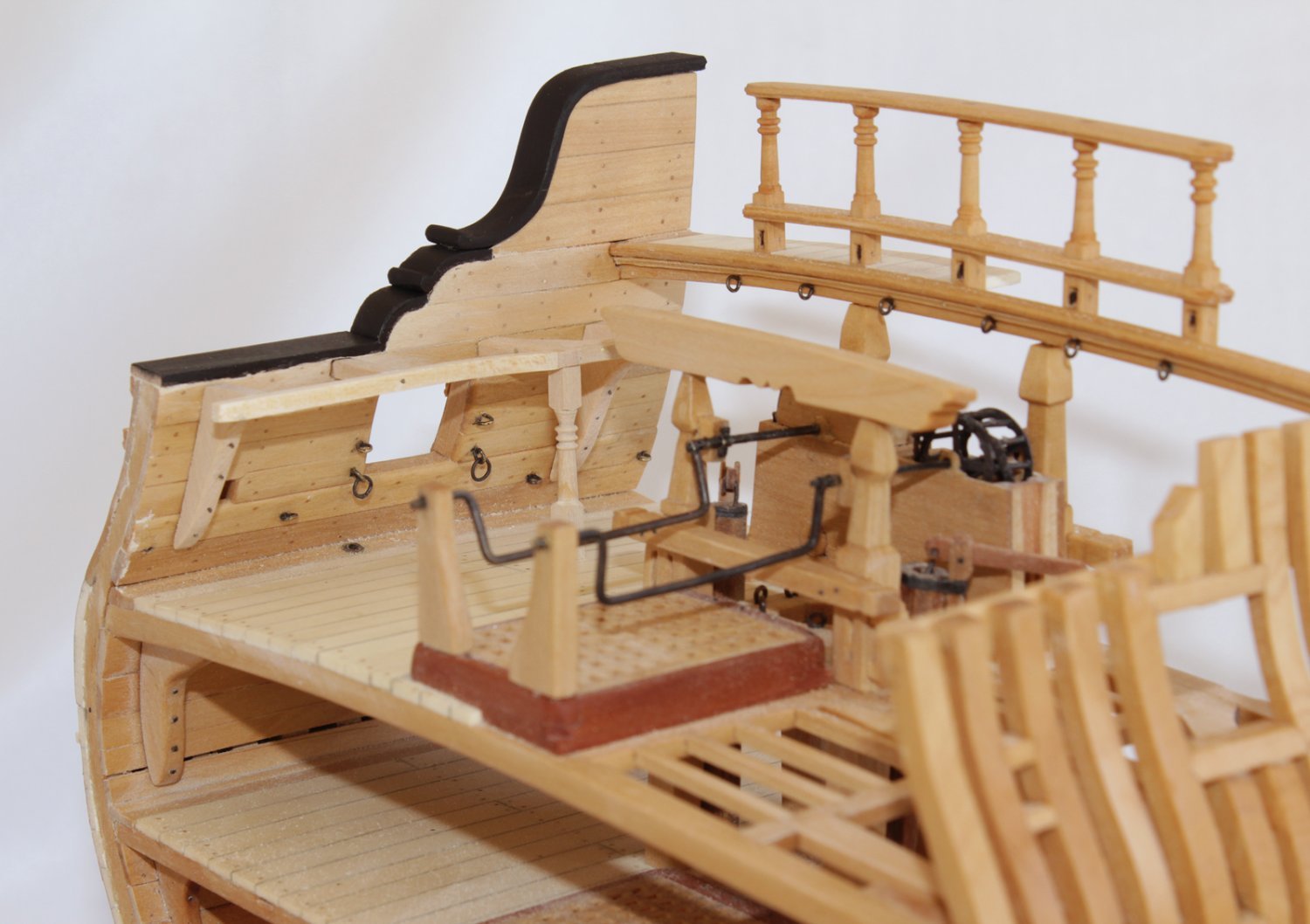
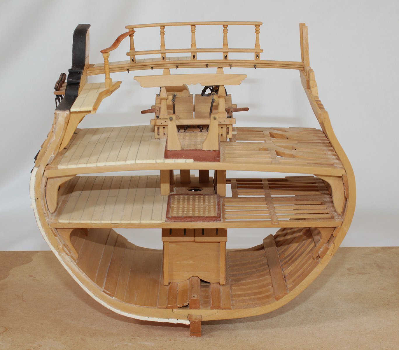
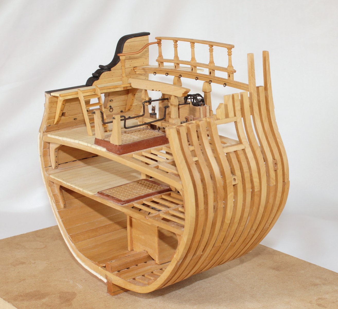
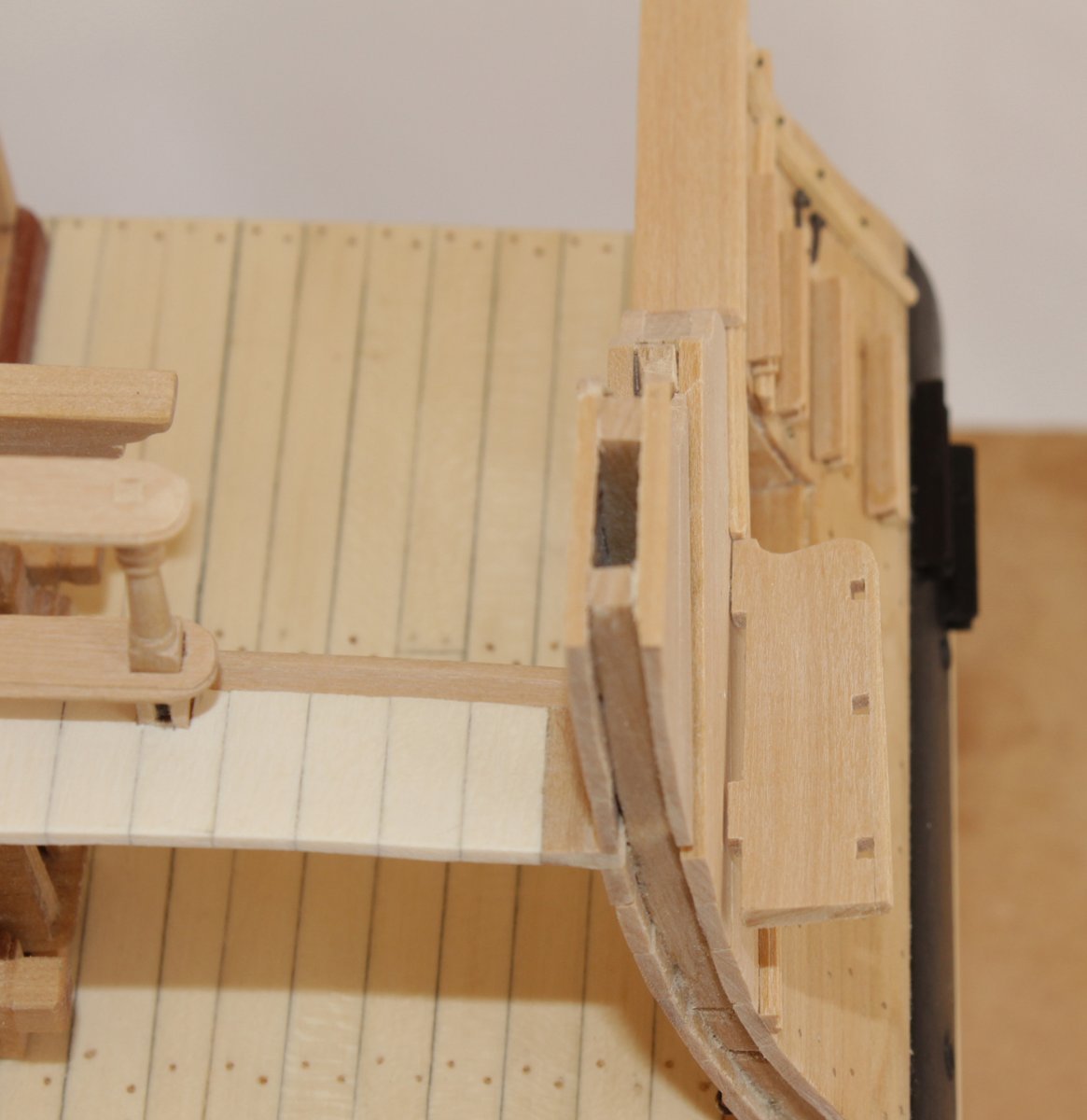
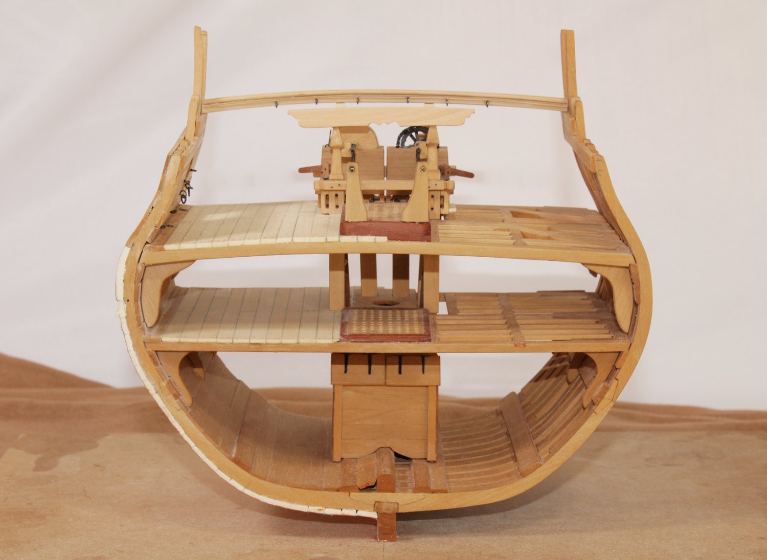
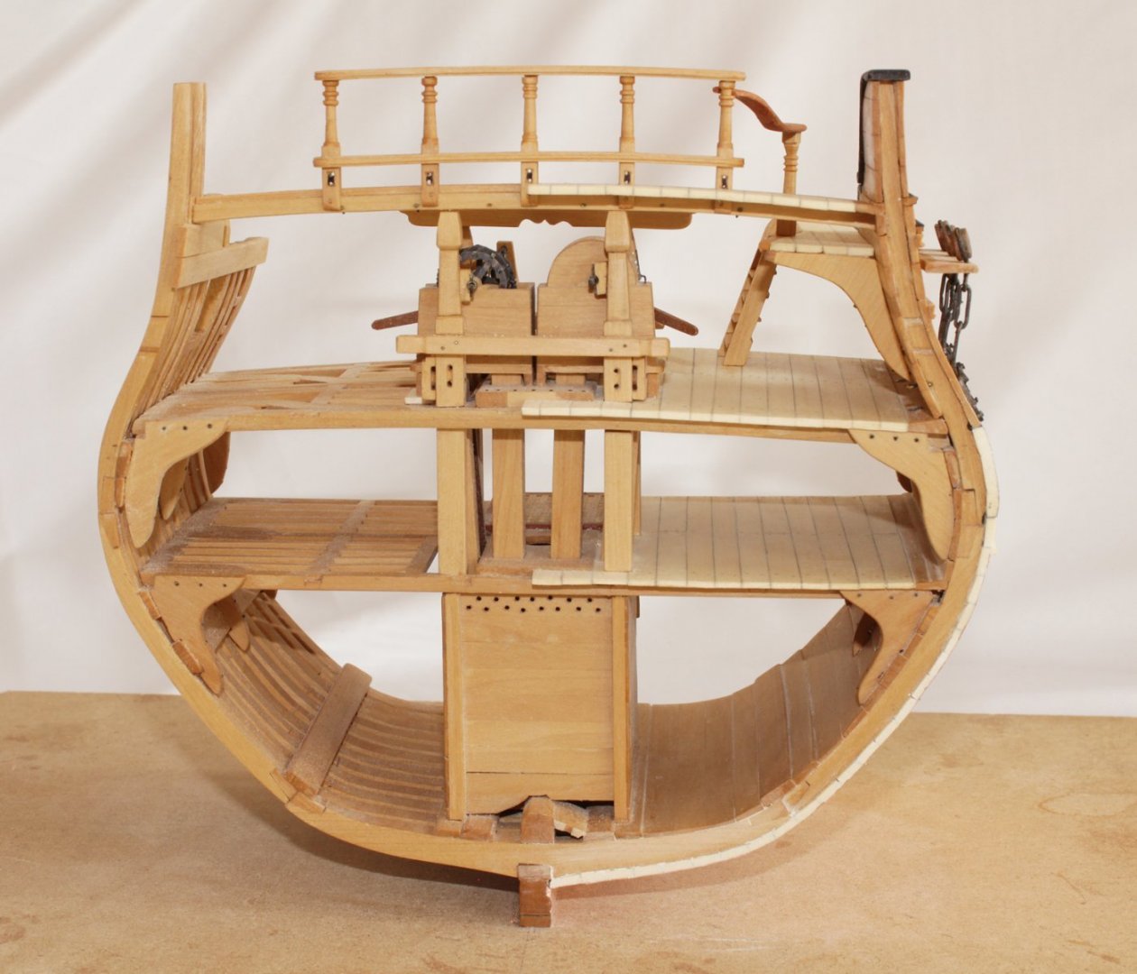
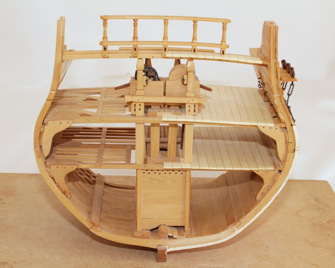
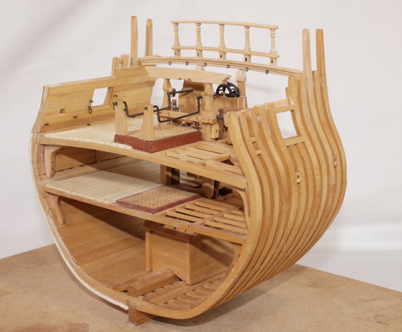
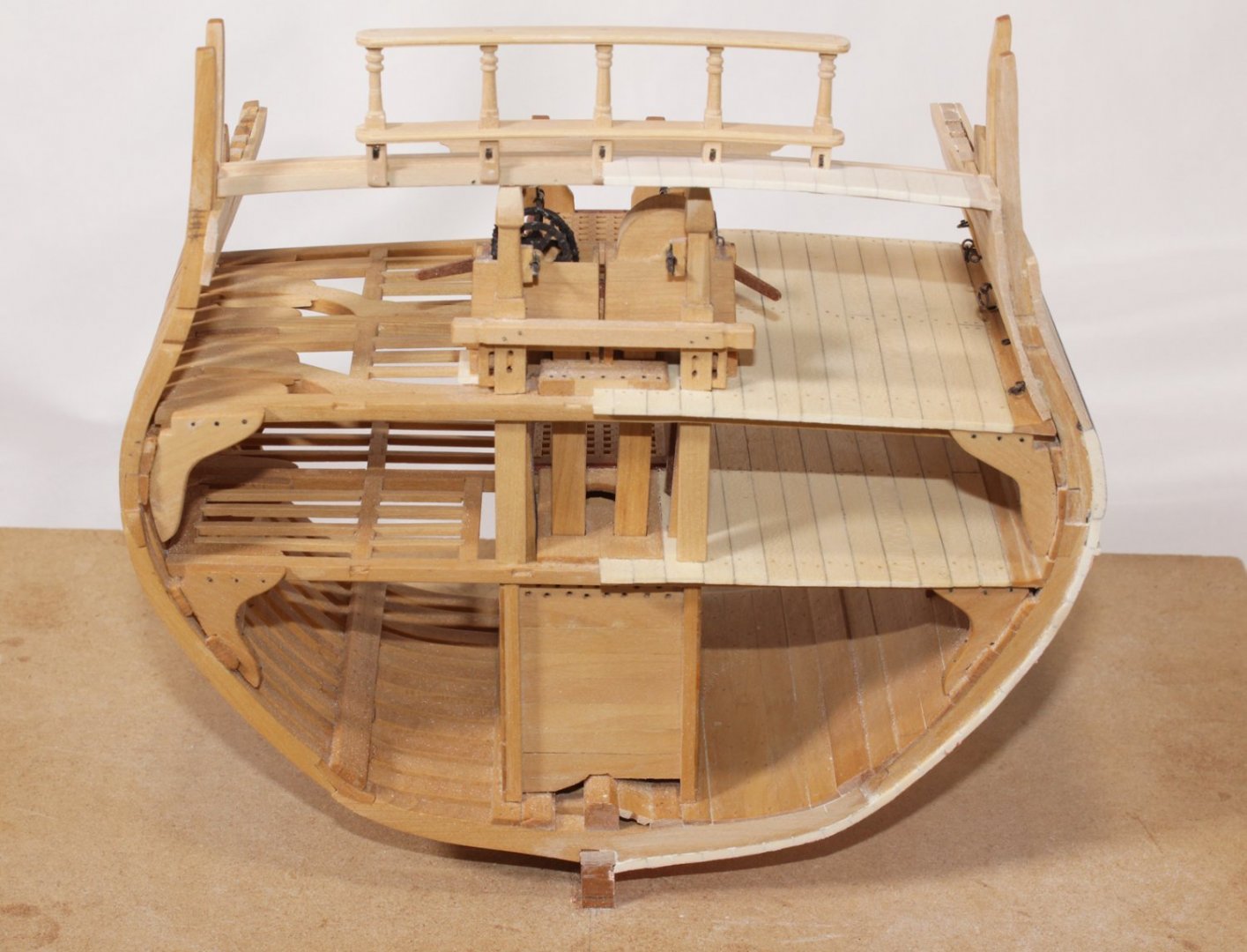
The last two items to address are the gangway and the ladder going up to it. The gangway is comprised of a frame of wood, secured to the bulwark with knees (two of them are visible in this cross section). The frame is then planked. I initially misinterpreted the drawing in the practicum and installed a stanchion between the deck and gangway. The location made no sense to me as it would have been in the way of the gun. The stanchion is actually between the gangway and the rail connecting it with the quarter deck. The rail was somewhat tricky to make; it is curved in two directions. There is a "fork" between the rail and the upper quarter deck rail stanchion and a tenon through which the gangway stanchion inserts. When I made this rail, I thought I was using castelo. After a coat of finish, it was apparent that this was pear. After these photos were taken, I removed the rail and made a new one from castelo. The last thing to make was the ladder. Echo is officially finished. All that remains is to clean her up, and decide how I want to mount her.


- 52 replies
-
- 33
-
-
-
-
Echo by tlevine - FINISHED - Cross-Section
tlevine replied to tlevine's topic in - Build logs for subjects built 1751 - 1800
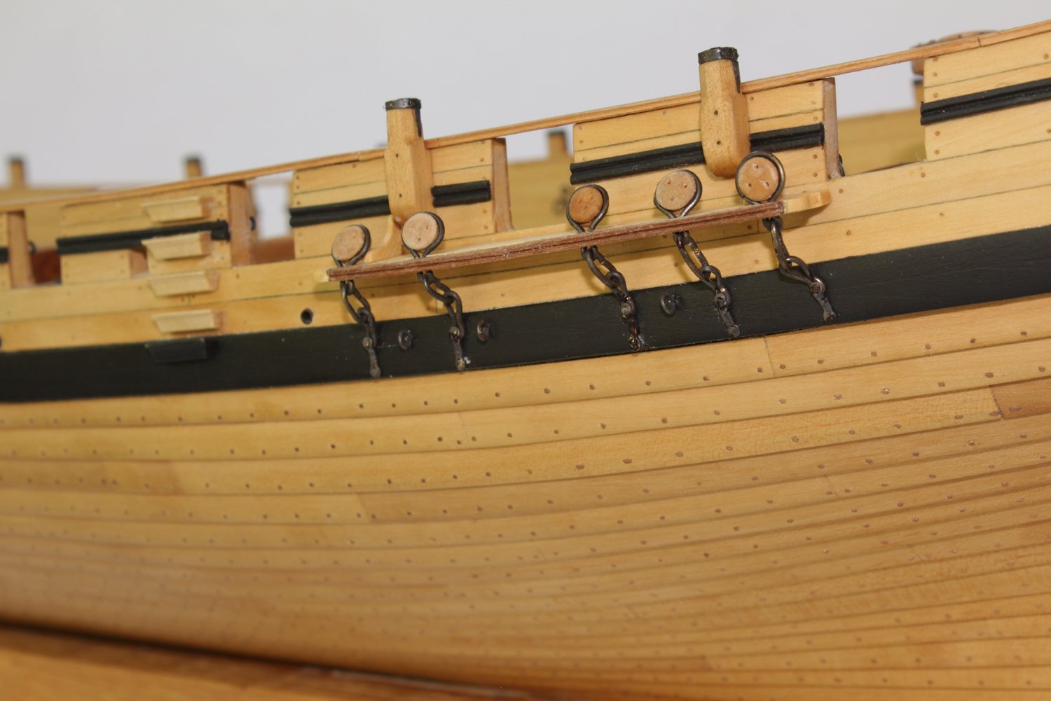
The channels were made and installed next. These were glued and pinned to the hull. The covering strip is only temporarily installed. These also have a carved edge, similar but slightly narrower than the sheer rail. The deadeyes were turned from swiss pear. The chains are brass, The middle link was silver soldered and shaped first. The toe link and deadeye binding were then installed. These were shaped and the deadeye installed after they were soldered. The ironwork was then blackened and given a coat of matte finish. The preventer plate was cut out from sheet brass. Next up was making the drift rail and hance. The hance is a section of rail that forms almost a ninety degree bend as it connects the drift rail with the planksheer. I tried several times to carve it from a single piece of costelo. I finally gave up and made it from three laminations, heat bent to shape. This has the same molded edge as the planksheer. Below the drift rail is the wider drift molding which terminates in a volute just behind the hance. We are now up to eight molding profiles. I decided to paint the rails and their extensions onto the hull, the planksheer and the drift rail. To prevent getting paint on the hull, the undersurface of these would be painted off the model, the rails installed and then the upper surface and edges painted. The planksheer offered no difficulty. Because the curvature of the roughtree rail was gentler, I was able to heat bend a strip of costelo to the required shape. The photo is after a few coats of very thin artist acrylic paint. It still needs cleaning up and a coat of finish applied.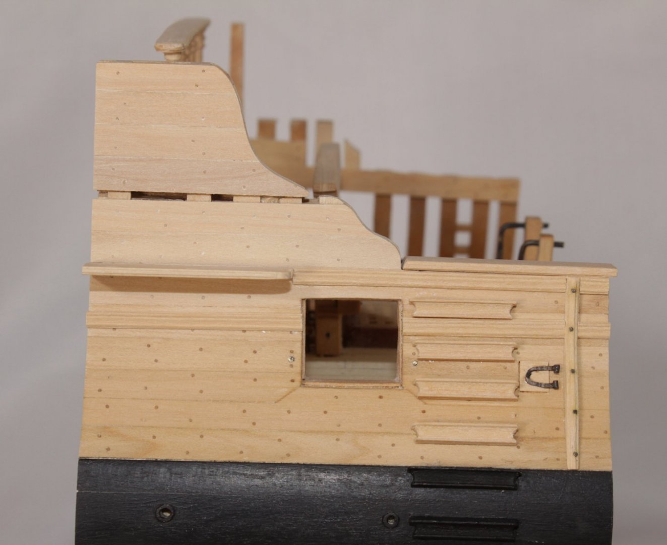


- 52 replies
-
- 25
-
-
-
Echo by tlevine - FINISHED - Cross-Section
tlevine replied to tlevine's topic in - Build logs for subjects built 1751 - 1800
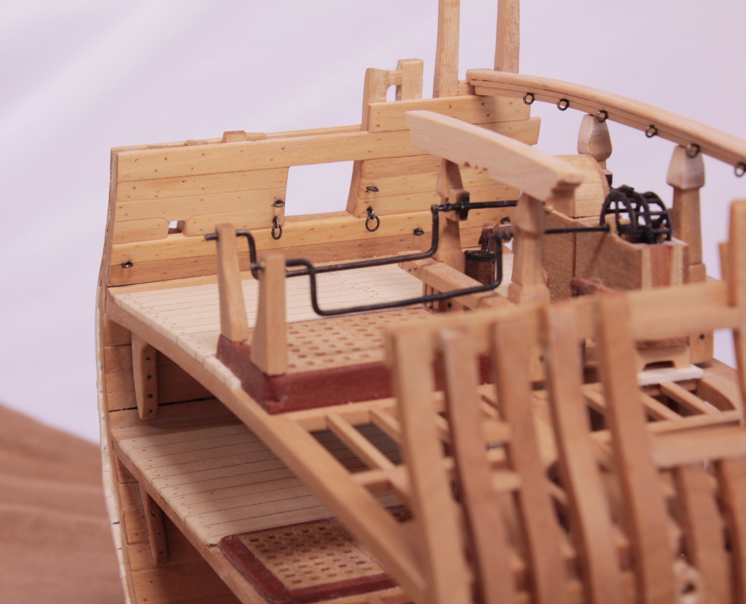
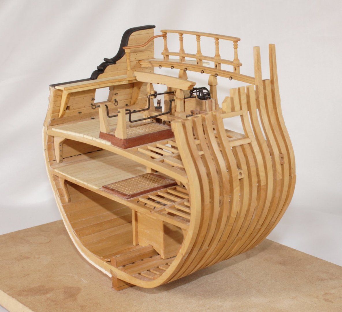
The oar port lid has been installed. The hinge is flattened copper wire and the knuckle is brass rod. My metal skills are insufficient to build a functional hinge this tiny, so the lid is glued in place. Although the plan shows two fenders, I only had room for one. I must have made a measurement error at the beginning of the build and I refuse to start over! The outer face of the fender is carved with a scraper and bolted to the hull. I had to make five scraper shapes for the various fittings seen in the picture. The steps were made in one long strip which was cut to length and the side curves were made with a U-chisel and files. Aft of the gunport are the holes for the pins which will attach to the channel.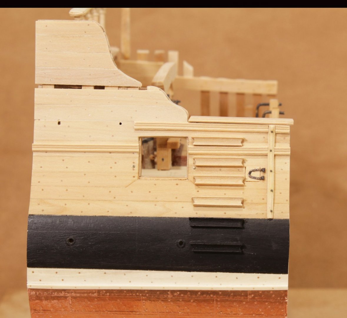
- 52 replies
-
- 20
-
-
I am building the Echo cross-section from Admiralty. The practicum is fantastic. Take a peek at my progress to date.
-
Try this. Lay a piece of paper over the previous plank and gently rub a pencil along the edge. This will give you the exact shape of the previous row and you can use that as a template for the next plank.
-
Echo by tlevine - FINISHED - Cross-Section
tlevine replied to tlevine's topic in - Build logs for subjects built 1751 - 1800
Druxey, there is a lot more to go. I have just finished the upper works planking and will begin the rest of the hull "extras" next. I am trying to decide whether to install the gangway. Of the two sets of plans I have for Echo, one shows her with a gangway (ZAZ4200) and the other does not (ZAZ3837). -
Echo by tlevine - FINISHED - Cross-Section
tlevine replied to tlevine's topic in - Build logs for subjects built 1751 - 1800
Thank you for all the likes, Michael, I think the notations are a new feature of the forum software. -
Echo by tlevine - FINISHED - Cross-Section
tlevine replied to tlevine's topic in - Build logs for subjects built 1751 - 1800
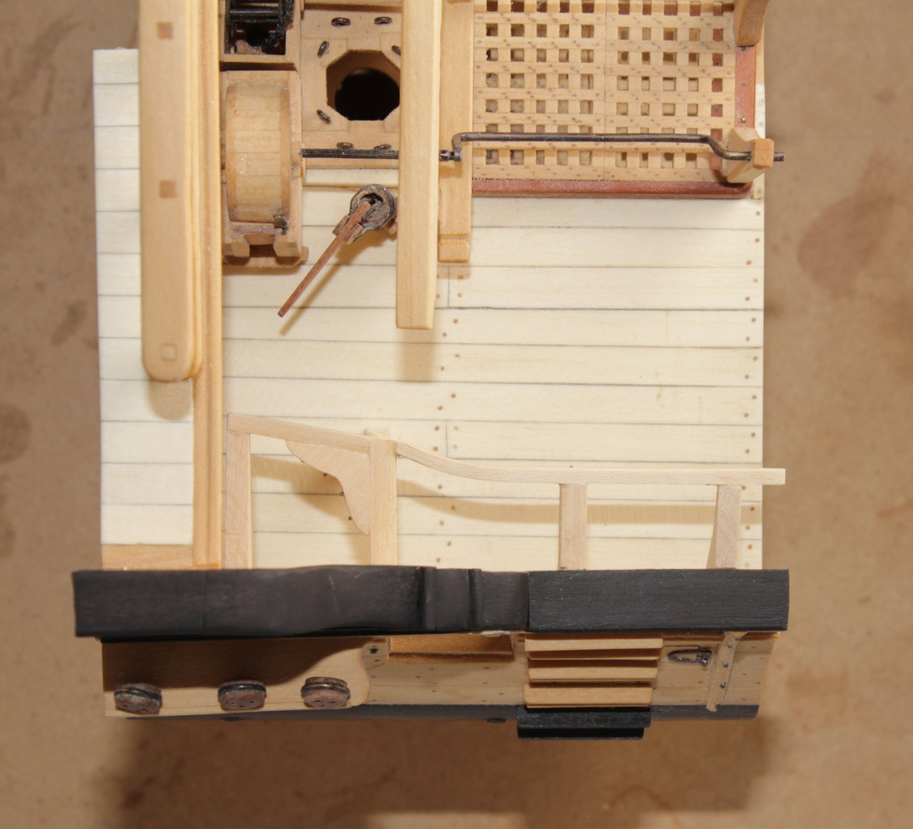
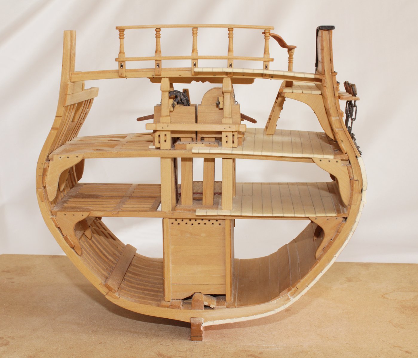
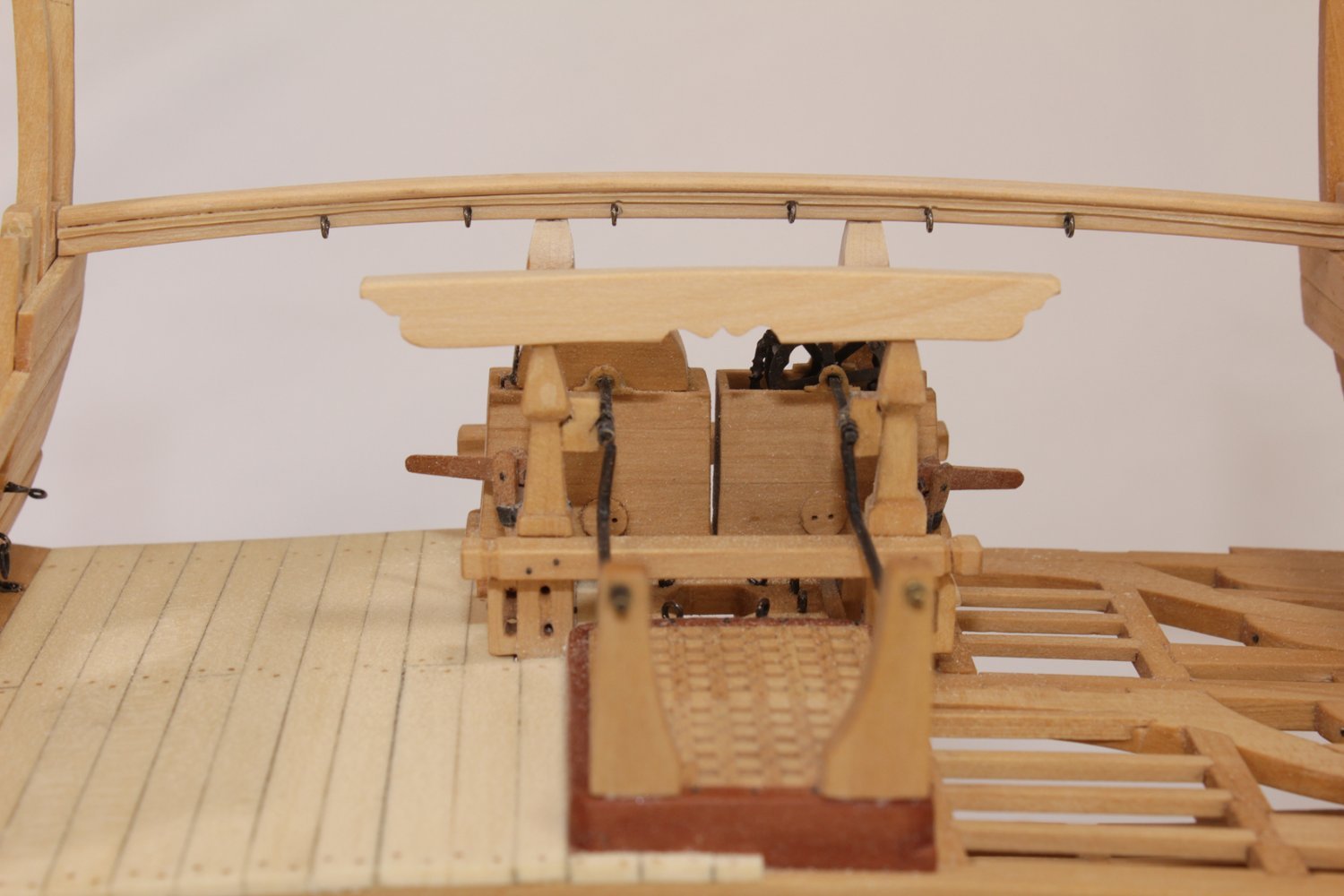
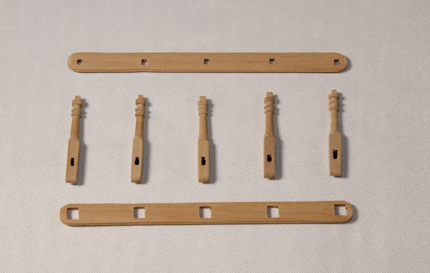
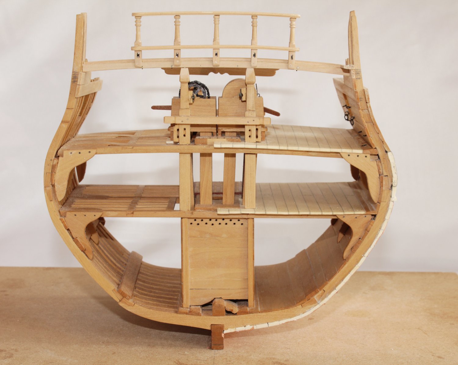
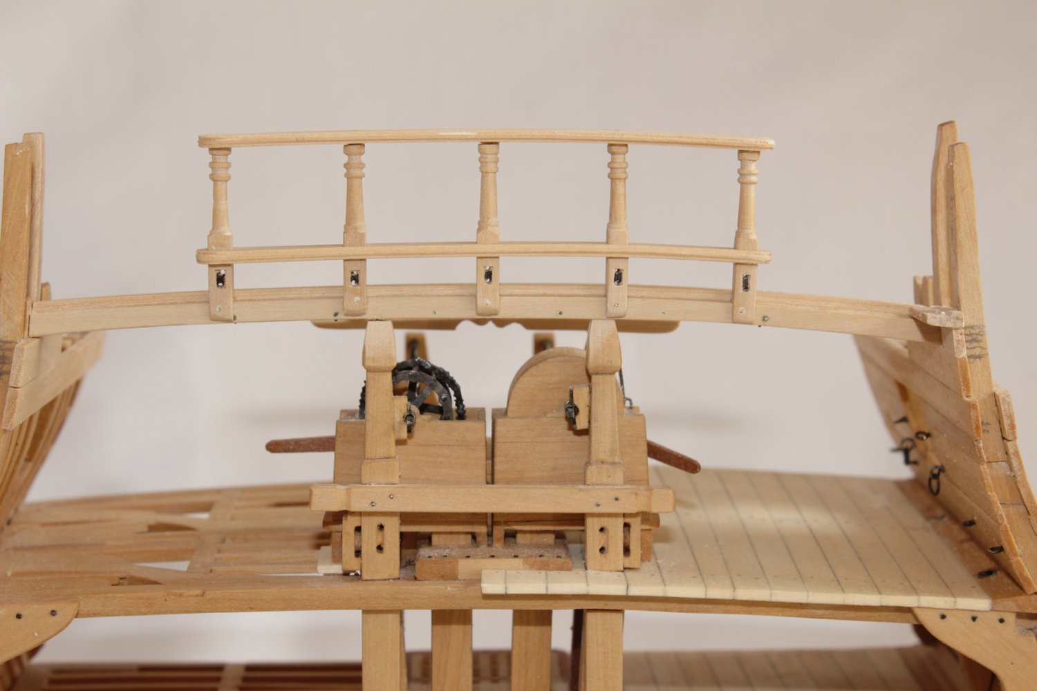
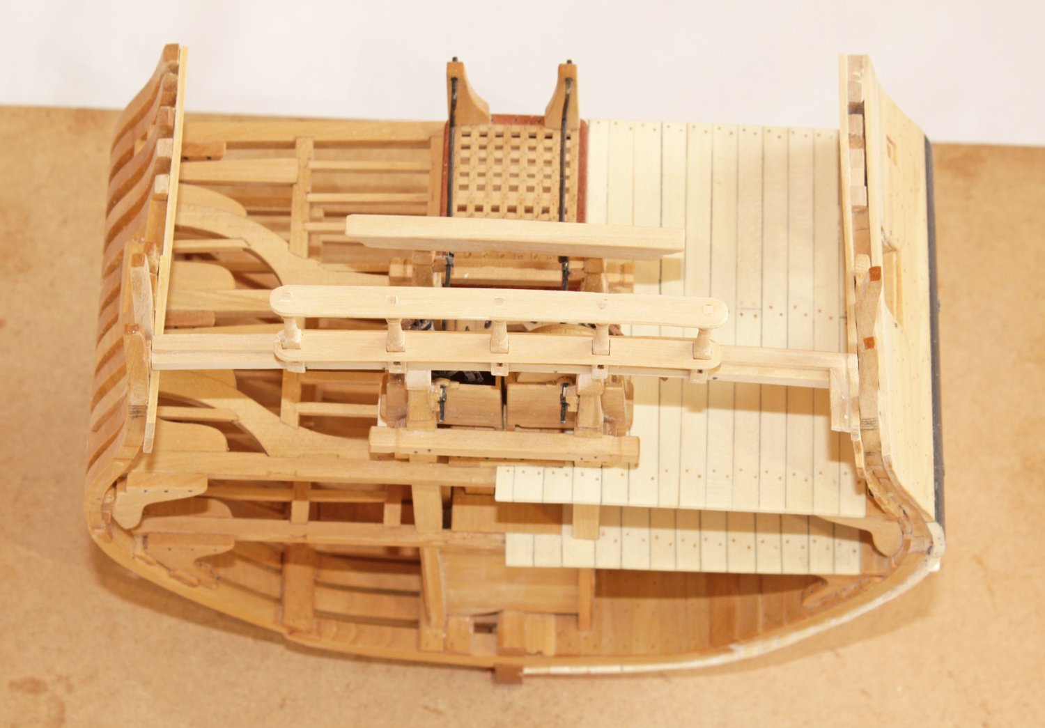
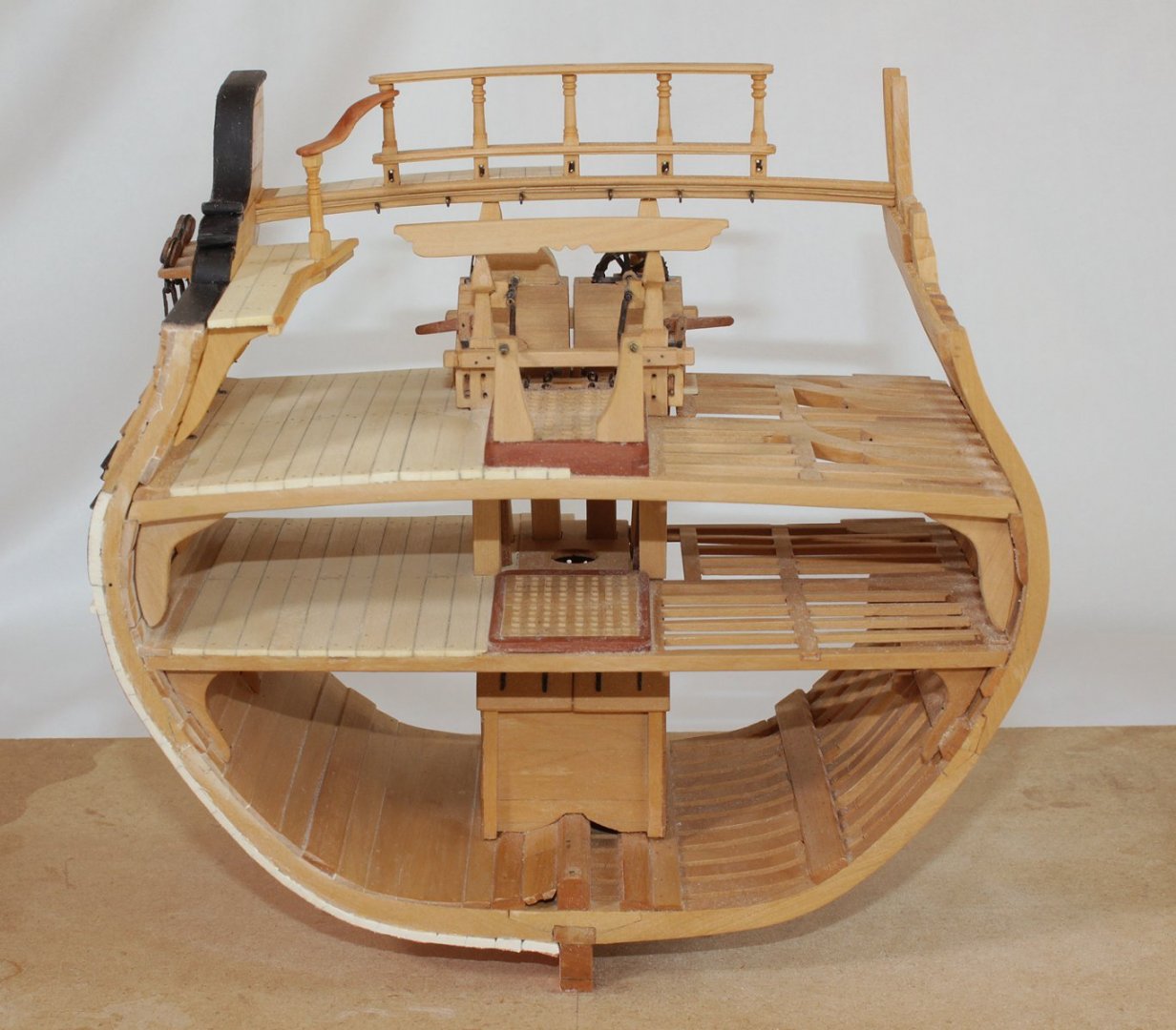
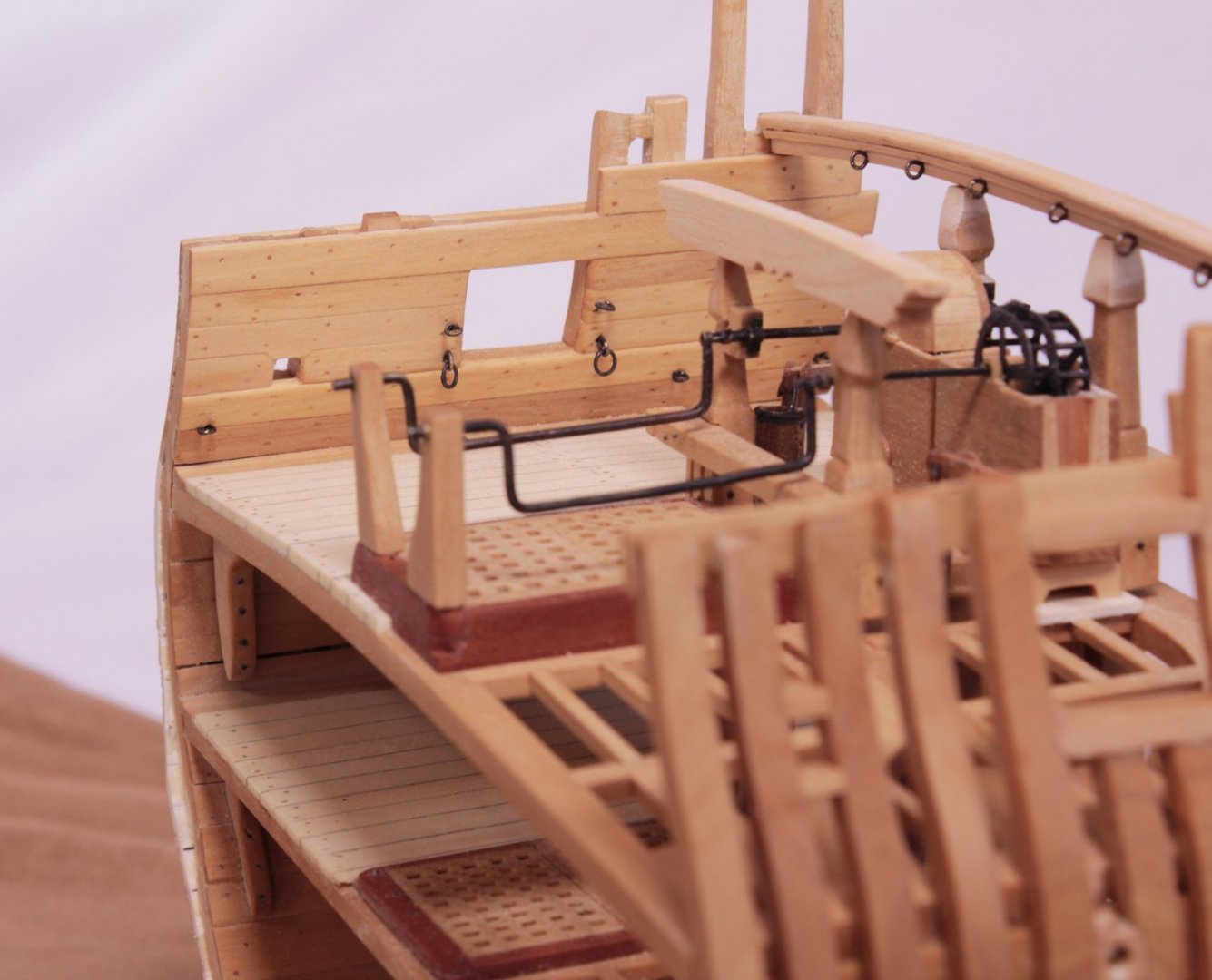
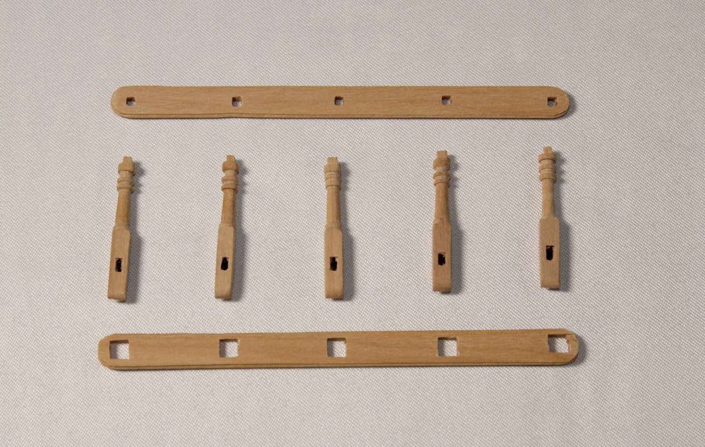
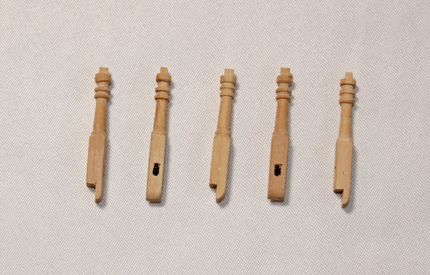
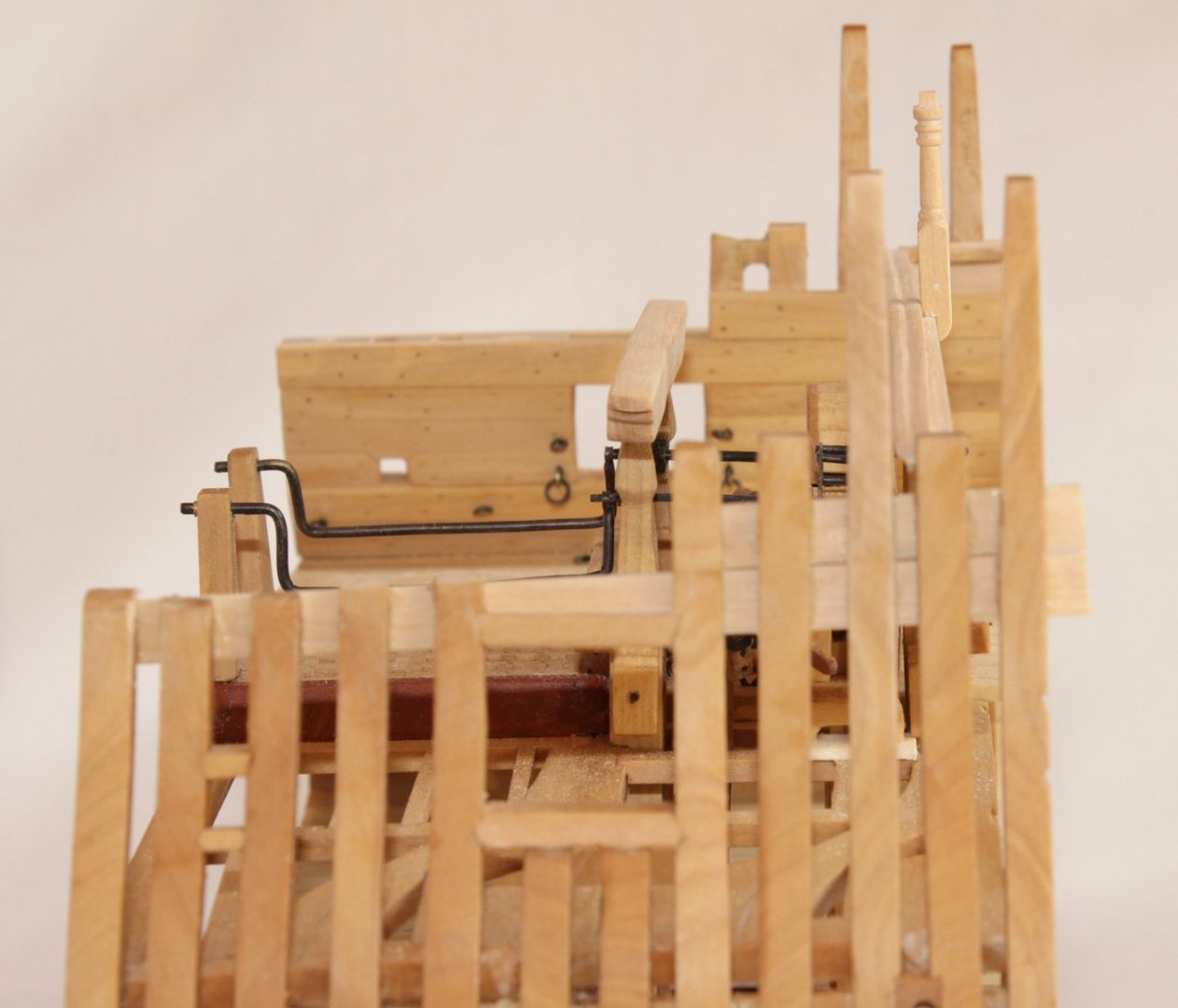
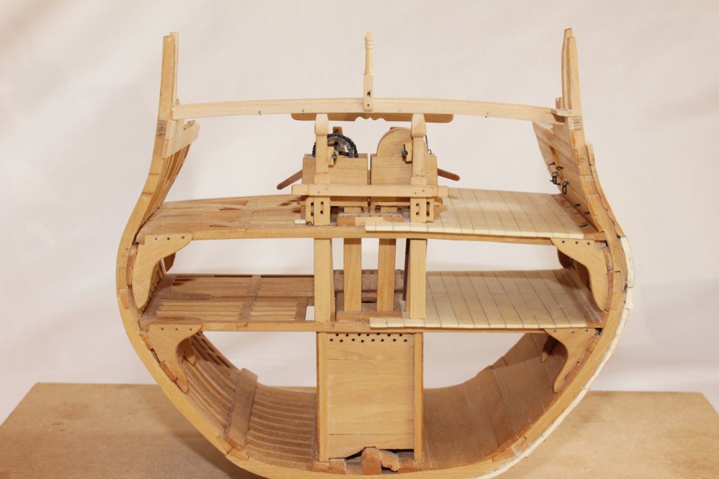
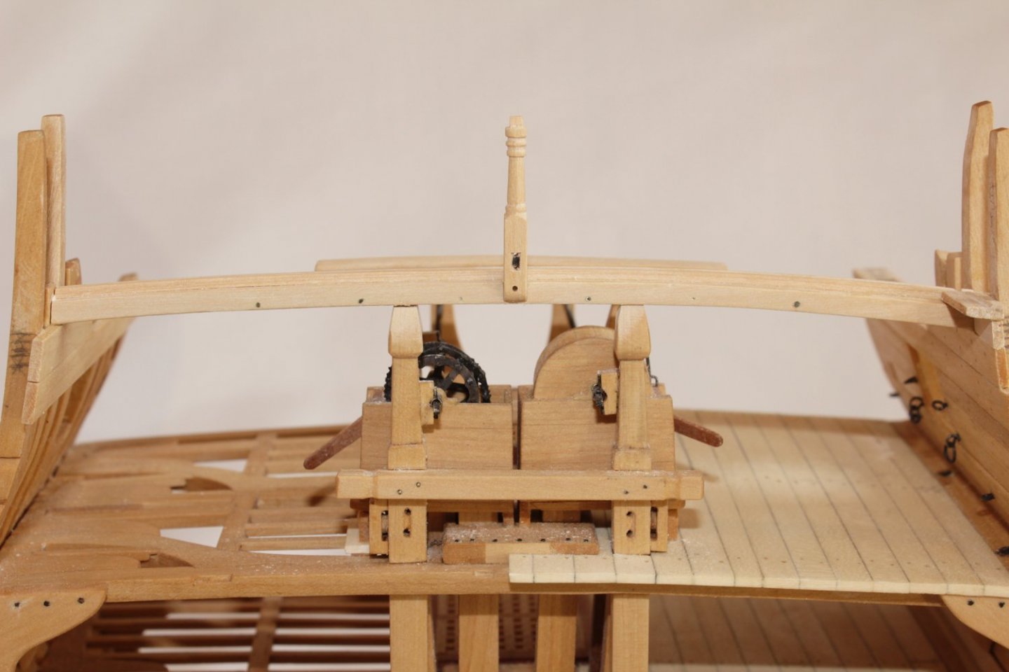
I made the gallows and installed it onto the bitt pins. To keep it secure, I drilled the pins and the gallows for a brass rod, which was inserted. The inner bulwark planking and the bolts and rings for the gun were installed. The breast beam was made up of three pieces. The beam itself was made, using the pattern found in the practicum. A rounded-over piece of wood extended forward from the beam. This provided a step for the deck planking to rest against. Quarter-round was glued under the rounded-over piece. Rings were inserted through the rail and the bolts can be seen on the aft side of the breast beam. The quarter deck railing was next. The rail assembly consists of five stanchions, an upper and a lower rail. The stanchions are morticed to allow them to be bolted to the aft side of the breast beam. These were made up on a lathe. A sheave was located below the lower rail. I simulated the sheave by drilling and squaring off the sheave slot and painting the area between black. The centerline stanchion was glued and pinned first. In these pictures you can see the rebate for the deck planking on the beam. Once this was secure, the lower rail was inserted over the stanchion; this acted as a template for the locations of the remaining stanchions. They were inserted through the lower rail and spacers were used to keep the rail at a constant distance from the beam. The stanchions were then glued and pinned. After they were completely dry, the lower rail was glued onto them. The upper rail was installed. Because some of my tenons were not exactly the size of the openings in the upper rail, I shortened them so they did not extend all the way through the rail. Dummy tenons were inserted and the top of the rail sanded smooth. Finally, short segments of deck planking were installed.


- 52 replies
-
- 22
-
-
-
Brass Blackening Building Time Survey
tlevine replied to Dave_E's topic in Metal Work, Soldering and Metal Fittings
I agree with Dave and Pat. I typically use a 3:1 dilution (water:blackener). Before I attempt any blackening, the parts are either soaked in vinegar or warm Sparex. If they don't look sparkling clean going into the blackener, they will not look good coming out. If you use Sparex, any forceps you use to remove the parts must be made of copper. Several short soaks, polishing between each one (wearing gloves so the oils from your hand are not transferred to the part) will give better results than one long bath. -
HMS Bounty by AdamA - 1:48
tlevine replied to AdamA's topic in - Build logs for subjects built 1751 - 1800
Somehow, the words CA and temporarily don't belong in the same sentence. Why not PVA? Dissolves easily in isopropanol. -
I'm glad you find all that wedge cutting easier! 😄
-
Thank you, Mike. The loss of these books would have been a tragedy to the hobby.