


garyshipwright
-
Posts
901 -
Joined
-
Last visited
Content Type
Profiles
Forums
Gallery
Events
Posts posted by garyshipwright
-
-
Thanks Guy's. I do still have just a tad of planking that I want to do at the hatches. Other then that maybe a clear finish over top of it, to bring out the detail of the pegs and seams.
Gary
-
Merry Christmas and a happy new year every one.
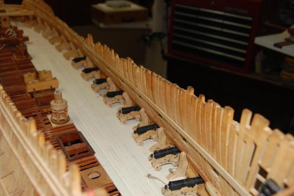
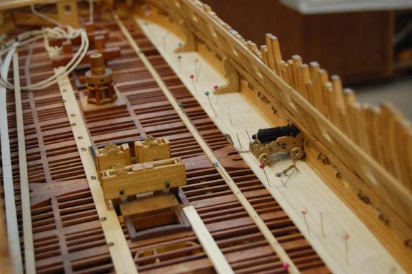
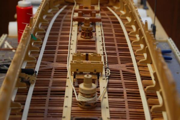
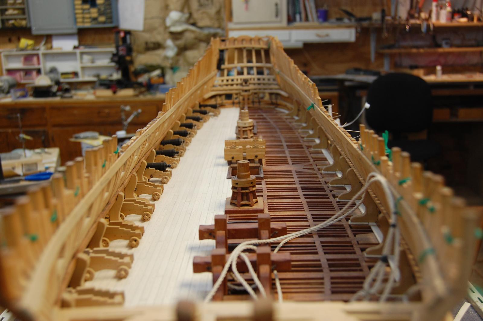
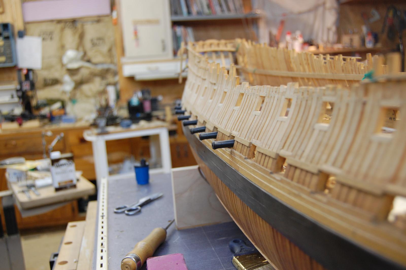
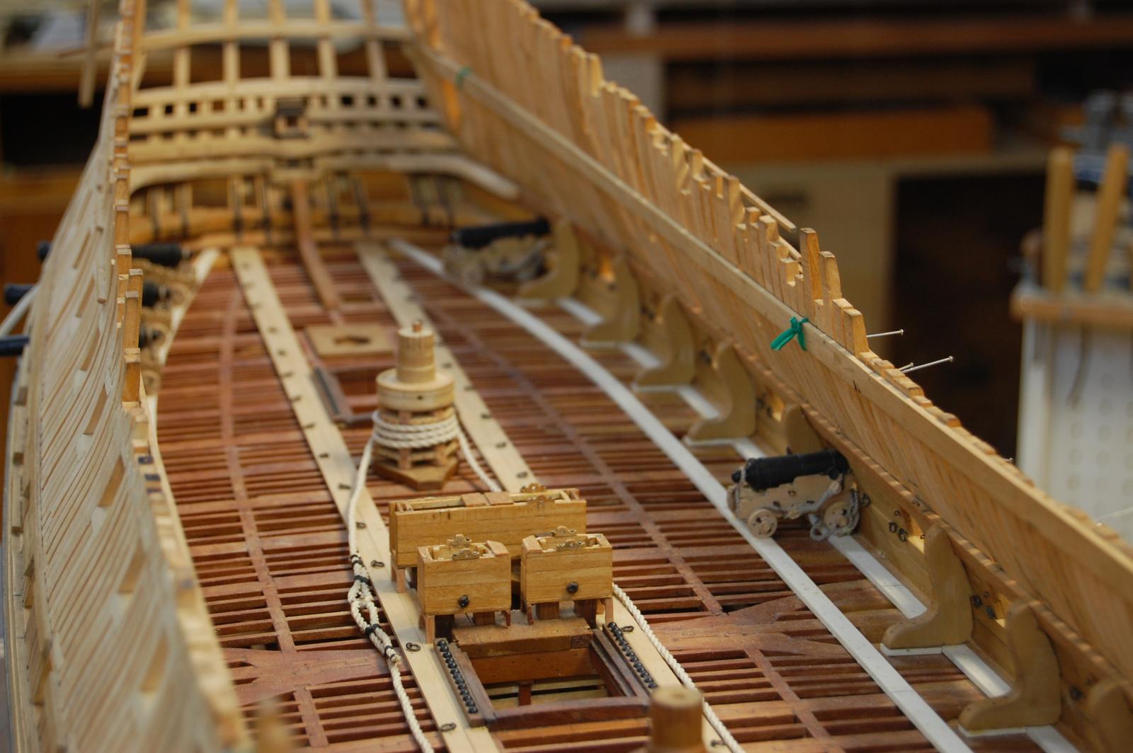
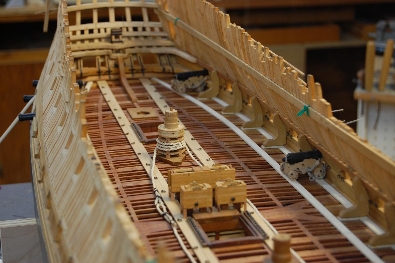
Thanks to every one with their kind words. It seems that I have a small up date on Montagu gun deck. I took off the planking I installed the first time, or was it the second time but instead of installing just enough for the gun's, ran it all the way over to the hatch ways and left one side unplanked. The deck planking is silver maple and boy is it white and every thing has been pegged but have not done any kind of stain on it. Thinking about toning it down but not sure of the how or with what so if you have any ideal's please let me know. Have been expermenting but not happy with what am coming up with yet. Do know that Frolick used maplewood on his deck of his La Belle Poule, and looks real nice. Seems it is a honey oak color and doesn't blind you when you look at it, but havn't found out what type of maple and if you know what type maple and stain please let me know. The cannons are just sitting on the deck till other items get done and will be reloacted to a safer place once I start working on them again. Any way folks Merry Christmas and may you get that tool or kit that you been wanting for the past year.
Gary

- capnharv2, Jaxboat, harvey1847 and 16 others
-
 19
19
-
Hi Michael. Frolick shows how to make a mast in his book, The Art of Ship Modeling, on page 185. Its a very good book and does give one some insight's in to other items like casting cannons, framing and a whole lot more. Good book for your library.
Gary
-
Continuation
Hi Garward. Nice work sir and was wondering how do you make the round dome heads on the bolts? Do you have a jig and is it possible for you to show how you make other metal fiitings also for your works? Am very interested in how the good folks of the site make different item's in metal and yours are high on my list. Thank you sir. Gary
- michael mott and drtrap
-
2
-
Thanks Tim.
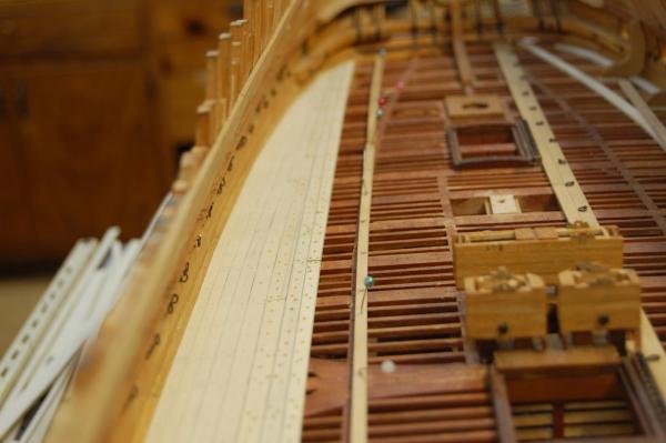
Hi Chris. I’ve played with it a bit. It is as thin as water. The best way I found to do it on
something this large is to use a cut up cotton tee shirt. Using rubber gloves of course I
dipped the tee shirt in the dye squeezed the excess out and then rubbed it in. At the ends
I did tape it off and used a small brush to better control it. I’m very happy with the way
it came out. After it dried I also installed three rows of planking below the wales. That
is the extent of hull planking I will do.
Hi Rusty. Nice build sir and seems that other's have allready taken the good word's so I am taking my hat off to you sir. Good job. Gary
-
Hi Gary
If you click on the accessories link at the top of the page then download the moulding pdf which is top left of the next page.Everything is listed with sizes and prices in Euros.Be warned some seriously nice kit and I know I for one could spend a fortune on there.Look out for the trunnion caps unbelievable detail!
Kind Regards Nigel
Hi Nigel. I downloaded the accessories PDF sir and the only item that I saw was bolt's with nuts and not clenched bolts. Is that the item? Thanks Gary
-
Thanks Nigel. I went to there site sir and nothing comes up or at leasty what I can see. Any more help would be grateful, knowing what sizes and cost of them also. Thank you again. Gary
-
Hi Alex. Have a question for you sir and wondering were you found the information. The clench bolts that you show on the outside of the gun ports, was this done on English ships? I thought that this was done on French ships but was hidden on English ships under the outer planks. Another question is how is this detail done, cast or metal work and can you show how this was made. Thank you sir. Gary
-
Your very welcome sir. As you said there was a lot of variations on the theme. Just wish I could find more of the top and butt showing on the gun deck and would have done Alfred's gun deck like that. One thing is for sure , when ever I get to the upper deck, her planks will be done in the top and butt. On the Montague, they are already in my stash of plans sir. Was going to copy my wale planking according to her's but went with, hum come to think of it, can't remember who.

Gary
-
Hi druxey.
I would normally agree with you sir but I found two plans that show the planking laid out at the NMM, of the Tremendous of 1784. Her gun deck shows straight planks drawn in,J3001 and her upper deck J3002 which does in fact show the outside planking in short lengths, cut in top and butt. Also there is that one of the unknown 74 which shows the upper deck with straight planks instead of top and butt planks. One thing that I have thought about Steel Plates of her gun/upper deck. Her gun deck shows the binding strakes and the upper deck show the lay out of the planking along with the top and butt plank's. Guess my question is why didn't he show the lay of the planking on the gun deck like he did for the upper deck. We may never know sir. The other plans are the Venerable of 1784, J3049 and J3052 which also shows the lay out of the planks and her upper deck only show straight planks along with the Cressy of 1807 of her upper deck which show's straight planks. From what I can tell druxey, only the plan of the upper deck of the Tremendous, shows the top and butt planking. May be you eyes can make out more of the detal sir. Do you have any primary plan number's showing the lay out of the planking for the gun/upper deck of any of them. Would be happy to have a look at them if that's ok with you.
Gary
-
Hi Daniel.
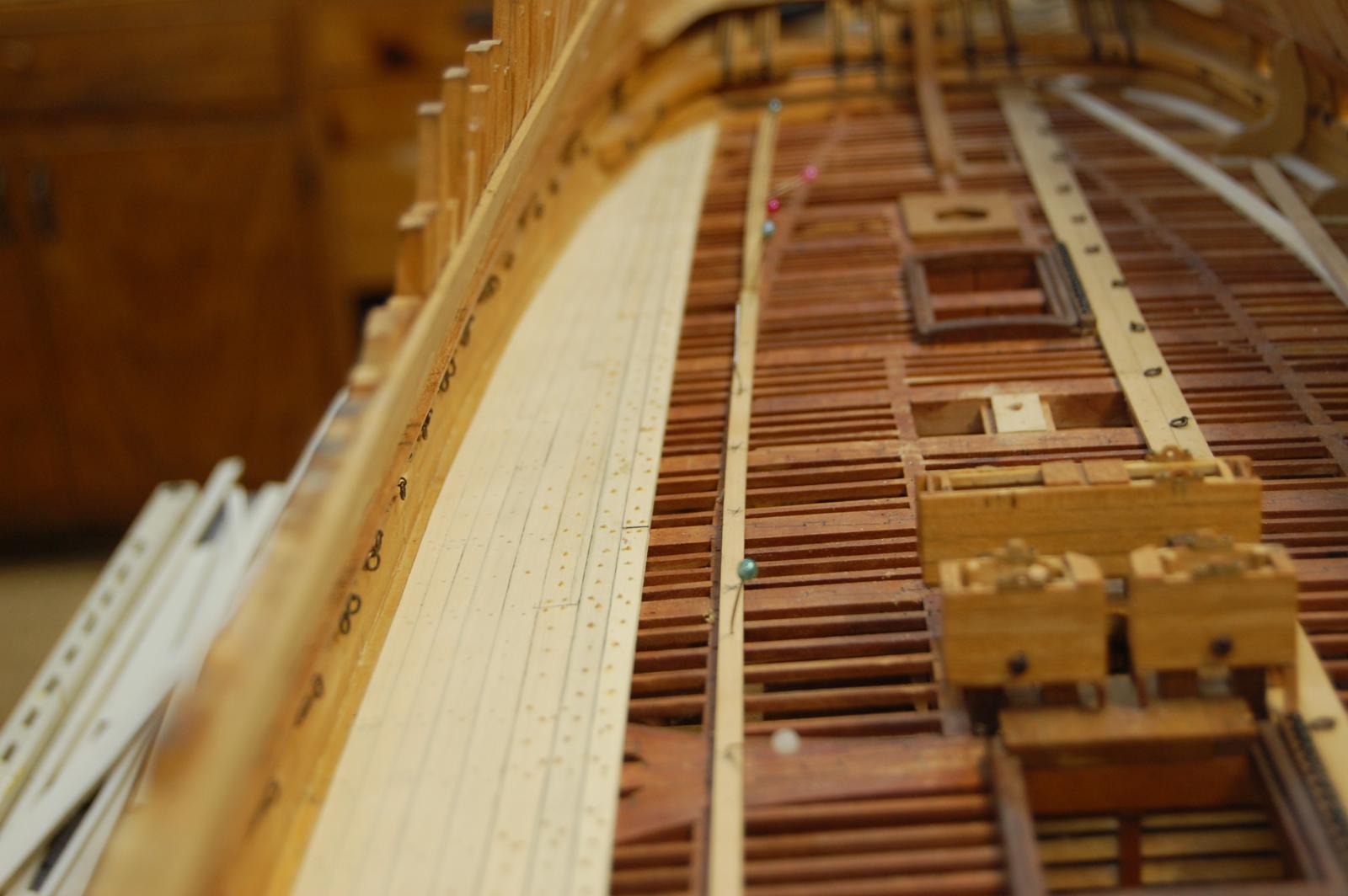
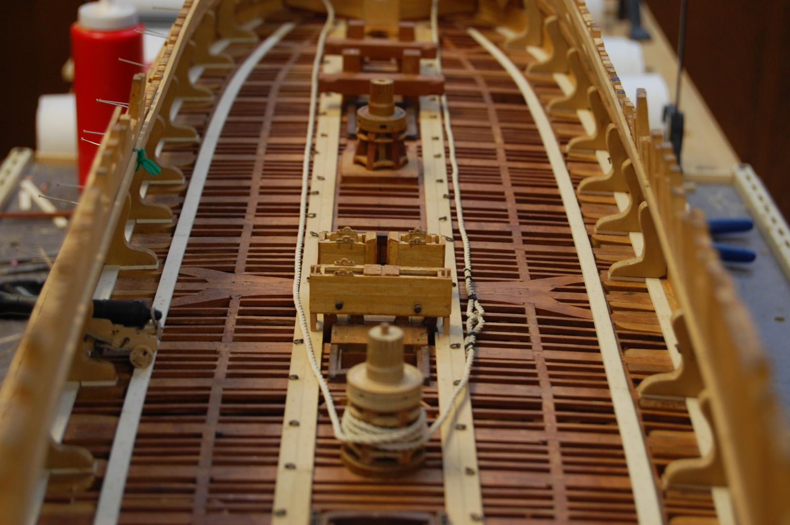
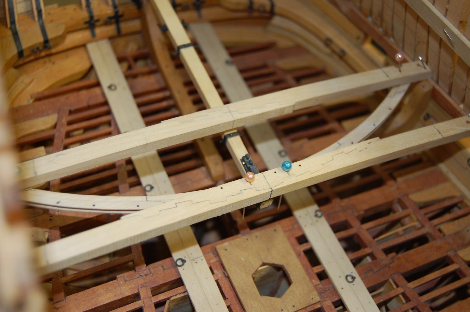
I have to agree with druxey sir and from researching the deck planking for Alfred it does look that planking was straight parallel planks after 18th. From researching this, to be some what accurate on Alfred, there just doesn't seem to be to many plan's showing how the planks were laid before 18th. at least what I can find . The ones I have found show curved planking before 1800, which has been reduced in width as it progress aft and fwd. Another thing I have found is that on the gun deck the outside plank's was joggled in to each other and the upper deck out side planking was worked top and butt, which seems to be different then what Peter Goodwing say's in his book. It does seem that this was not always done, looking at other plan's. They only give rules for the out side planking and the binding strakes which were to be oak along with the first shift which was also to be oak. It does seem that laying the deck is a lot like running the plank on the out side, a jig saw but a fun type jig saw. To me, laying the deck in different width's and in a curve looks more pleasing to the eye's. More in keeping with hand cut plank's, done in saw pits. Here is a photo of Alfred's deck laid so far. If you want to see some plan's showing the lay of the planking, go to the NMM site and look up Tremendous 1784, and J7921 unknown 74. Once you start getting in to the 1810 ,1815 time frame planking seems to have been layed much different.
Gary
-
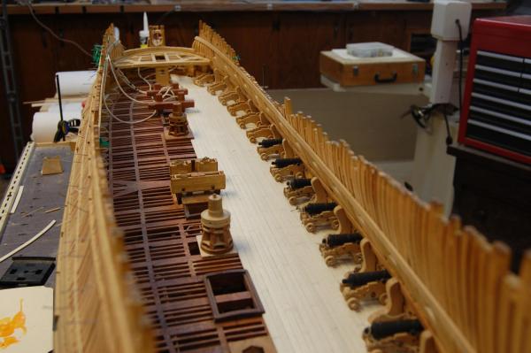
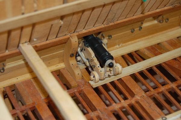
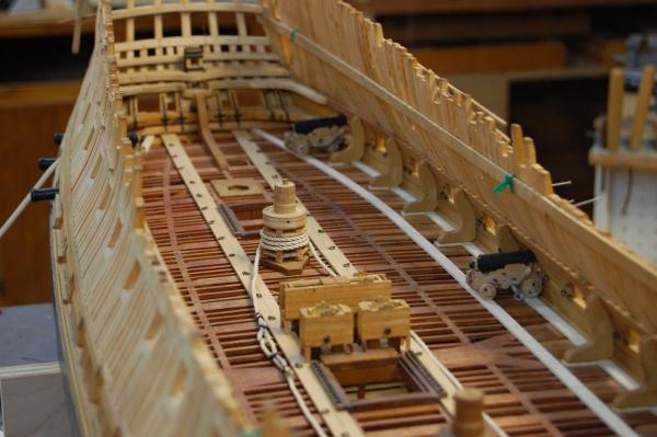
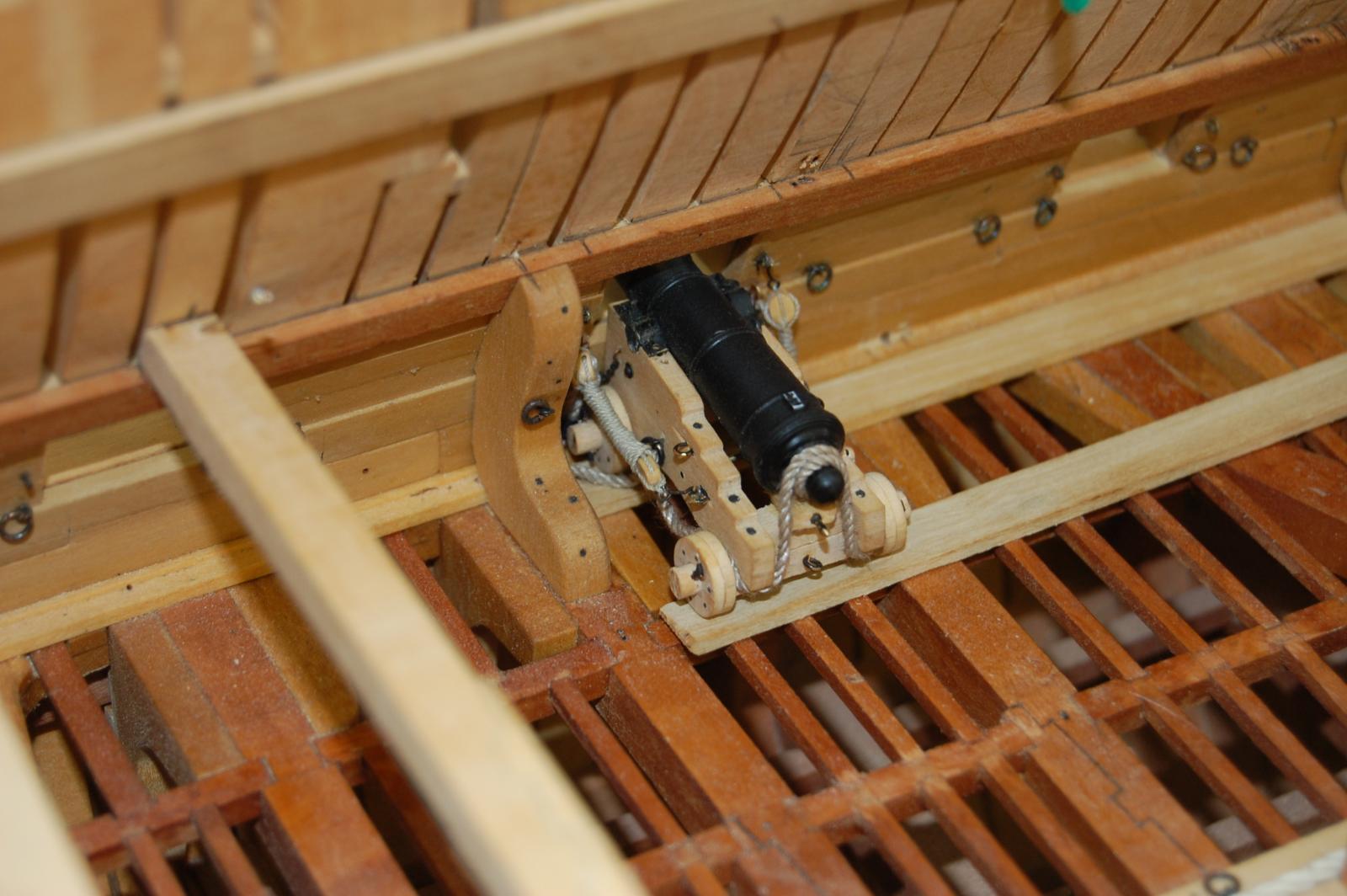
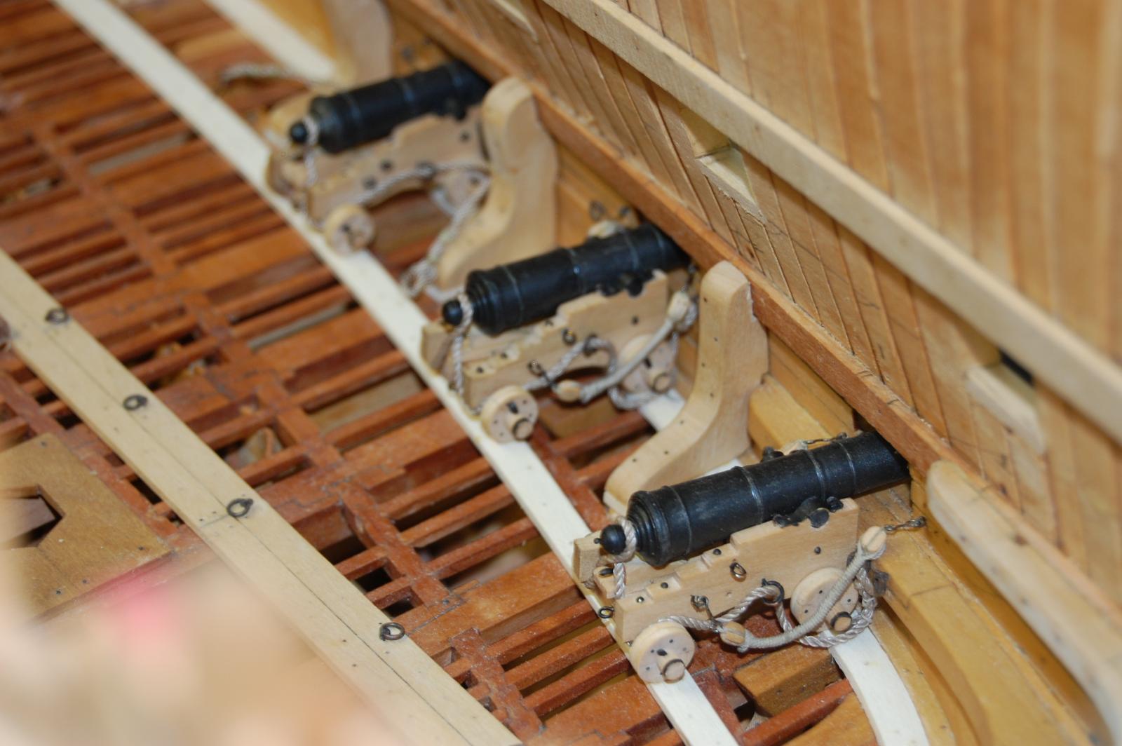
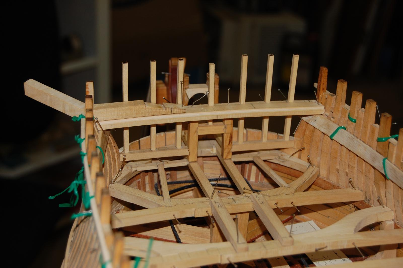
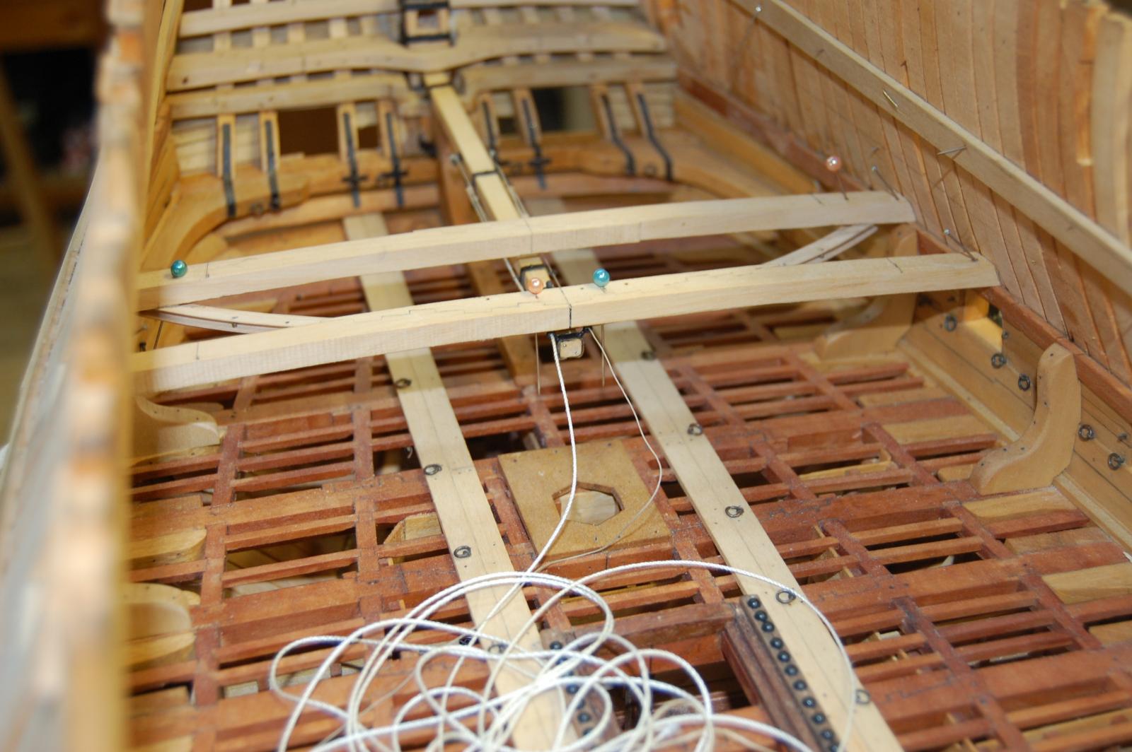
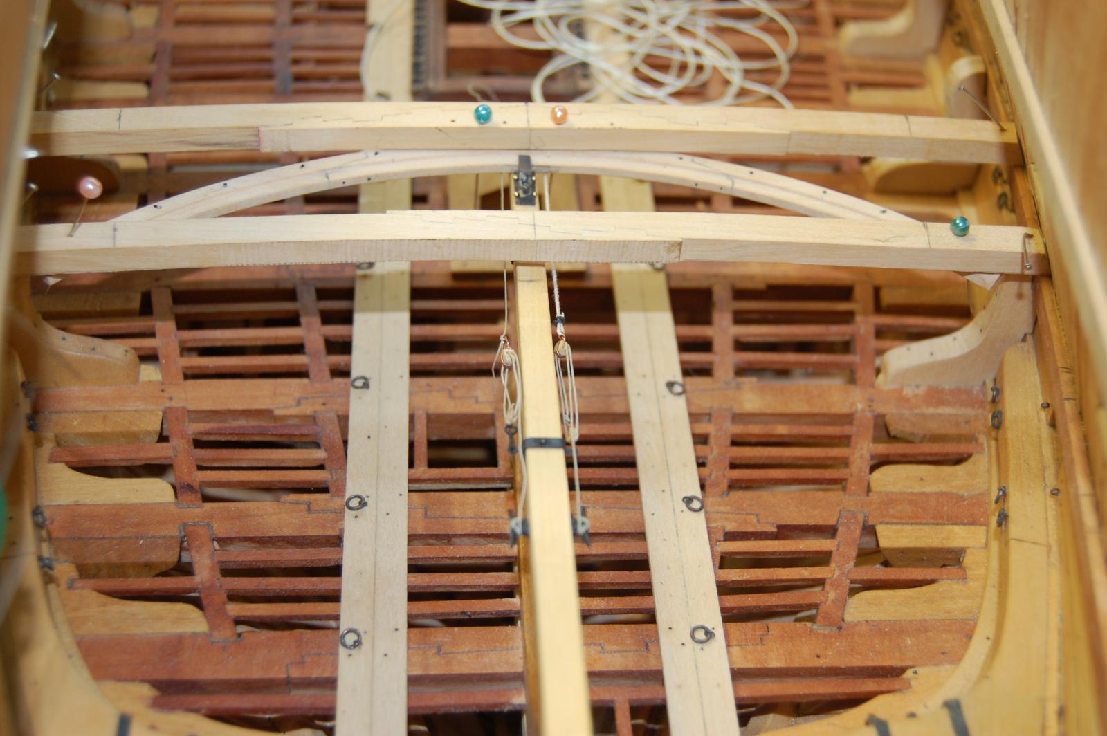
Hi Remco. Thank you very much sir. Am glad you like the cannons sir and seems that your statement is just a little modest but I do thank you. Here are some more photo's of the gun deck with a few more details. Am not sure if I will leave the curve planking which is due to the curve of were the back of the cannon truck's land. May just plank one side for cannon's and leave the other side alone. Reason is that I just don't want to cover all of the detail up and am sort of stuck on the do I want to or not decision. :mellow: Gary


-
-
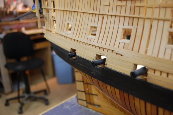
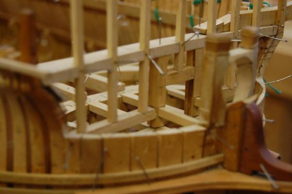
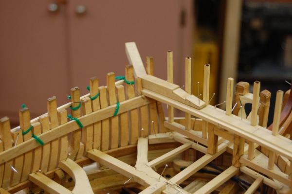
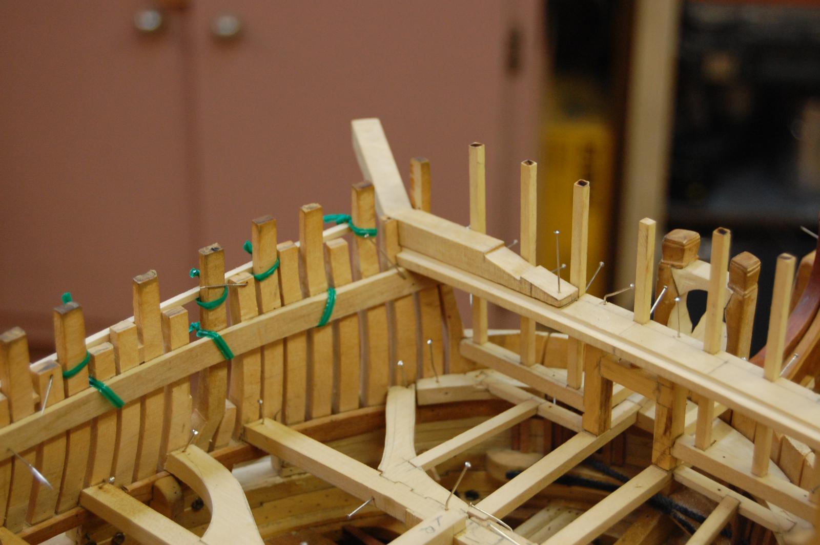
Hi Jim. Your post caught my attention about your cat heads and I don't believe that they was covered by the deck planking. Am not 100 percent sure but the most forward beam of the forecastle was very wide and had a rabbet on the aft edge for the planks to land on. On top of this beam the cat heads would set. I went through the book and most of the 50 gun ships show this type of set up if they had a beakhead bulkhead. Much like Alfred had. If you look in the 50 gun ship book by Winfield, on page 82 and 83 at the most forward end of the forecastle deck you will see this very wide beam. Also on page114 that plan gives a side view of the beam setting behind the beakhead platform. Am not quite sure why McKay shows the deck planking covering up the cat head beam which looks a little odd to me. Of course it being you ship, you can do it as you see fit sir. Here is a picture of Alfred's beakhead along with one of the cat heads waiting to be finished. You will also see the large beam with the rabbet in the photo's. Just something to think about and might help keep you from putting them on to early. Gary


-
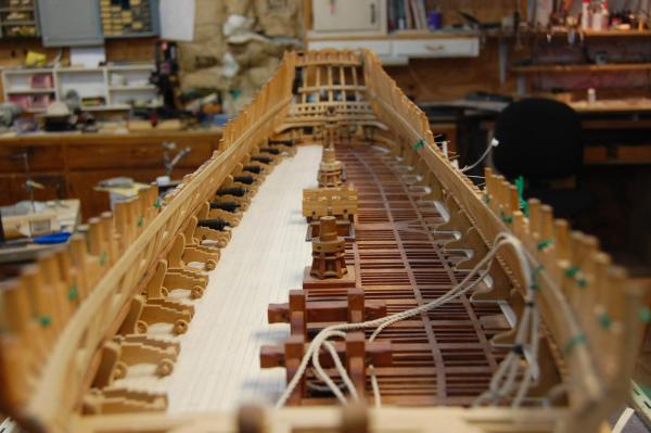
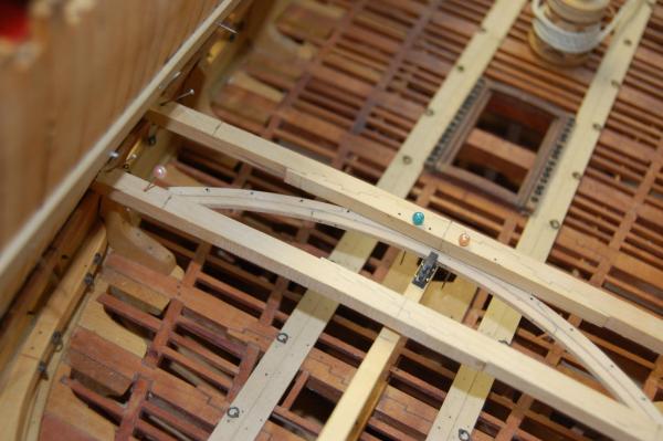
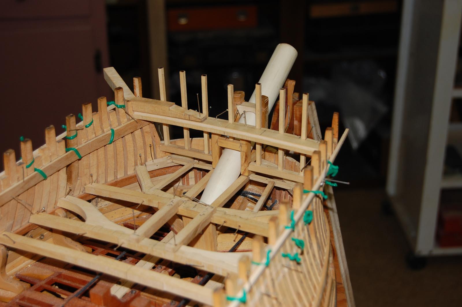
Hi guys and thanks for your kind word's. I finally have a little bit of a up date of Montagu. Work is keeping me very busy these days but did finally get the metal work done on her tiller. Do believe I will have to take the tiller out to get a good picture of it. Also have installed the sweep, gooseneck along with the tackle for the rope for the ships wheel. The plan is to try to install it like Ed did in one piece but being her wheel is two decks up might just not be the easies thing in the world but we will try. Enjoy the photo's folks hopefully I have more time in the future to work on her. Gary


-
-
Thanks druxey and Mark. Good point guys and maybe they didn't but to look at the other side, why did they come up with the locking collar and bolt as shown in Lavery's book Arming and fitting, on page 21. Lavery says that it was a method of rigging the tiller ropes 1790 and mention the spectacle frame near the after end. Says the drawing is based on plans in Rees Naval Architecture of 1819. It does make sense about the goose neck locking the tiller and rudder together which just might explain why nothing is mention about this. Thanks again guys.
Gary
-
Thanks druxey. When it comes to the AOS books am very careful with the information and try to back them up with some sort of primary research. There is one difference or missing item between the contracts and the French ship and that is the bolt that went through the rudder head and the iron strap, locking the two together on French ships. The English contract doesn't say any thing about this bolt so to me, this strap was more for strengthen the end of the rudder head, then to lock the two together. So going back to my question, how was they locked together during this time. Anyone have any ideals?
Gary
-
Hi Daniel. Yes sir that is the same set up in the Diana and Pandora. Any time frame on it when it may of come in to use? Thanks Daniel. Gary
-
Have a question for the good members of the form which I can't seem to find a answer for. In 1780 or at least that time frame how was the end of the tiller locked to the rudder and what time frame did this start. To give what info I have, I have checked Peter Goodwin's book, Sailing man of war, which on page 136, talks about the tiller locating plate but doesn't give a time frame for when it may of come in to use. You don't really see this on models or plans but EdT in his log shows the same set up as shown in the AOS Diana when he attaches the tiller to the rudder to lock the two together. The Pandora of 1779 also show the same set up on page 71 item 20/21. True Pandora should answer my question but I have some doubts of things in them. I also checked the French 74 gun ship by Boudriot and on page 132 vol 2 they show a iron U shape plate fastened to the aft end of the tiller where it fits into the slot, and this plate protrudes forward enough to leave room for a ring to be welded on either side. They show a pin passing through the plate and the rudder head and forelocked to lock the tiller to the rudder. . Now were my question comes in is due to the contracts I have and after reading them it seems to point to the way the French did it, which is why am looking for a time frame or maybe some of the members have a contract that tells us about the tiller locked that EdT shows in his build log. The contract's say that the tiller is to have a strap of iron around the after end, of sufficient length, let into the wood and bolted with bolts afore the rudder head and to have a hoop and eye on the fore end for the rope. The strap of iron seems to be much like the French and nothing like what Goodwin mention's in his book. Any one have more info on this. I like the way Pandora and Diana shows it but looking for a answer to this one. Thanks in advance for the help guy' and gal's.
Gary
-
Thanks Grant and Mark.
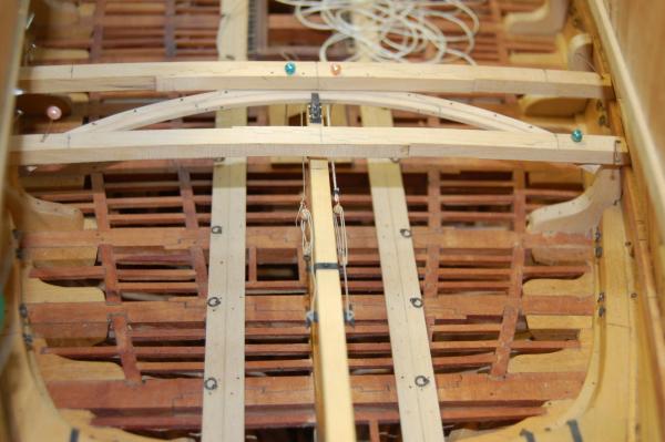
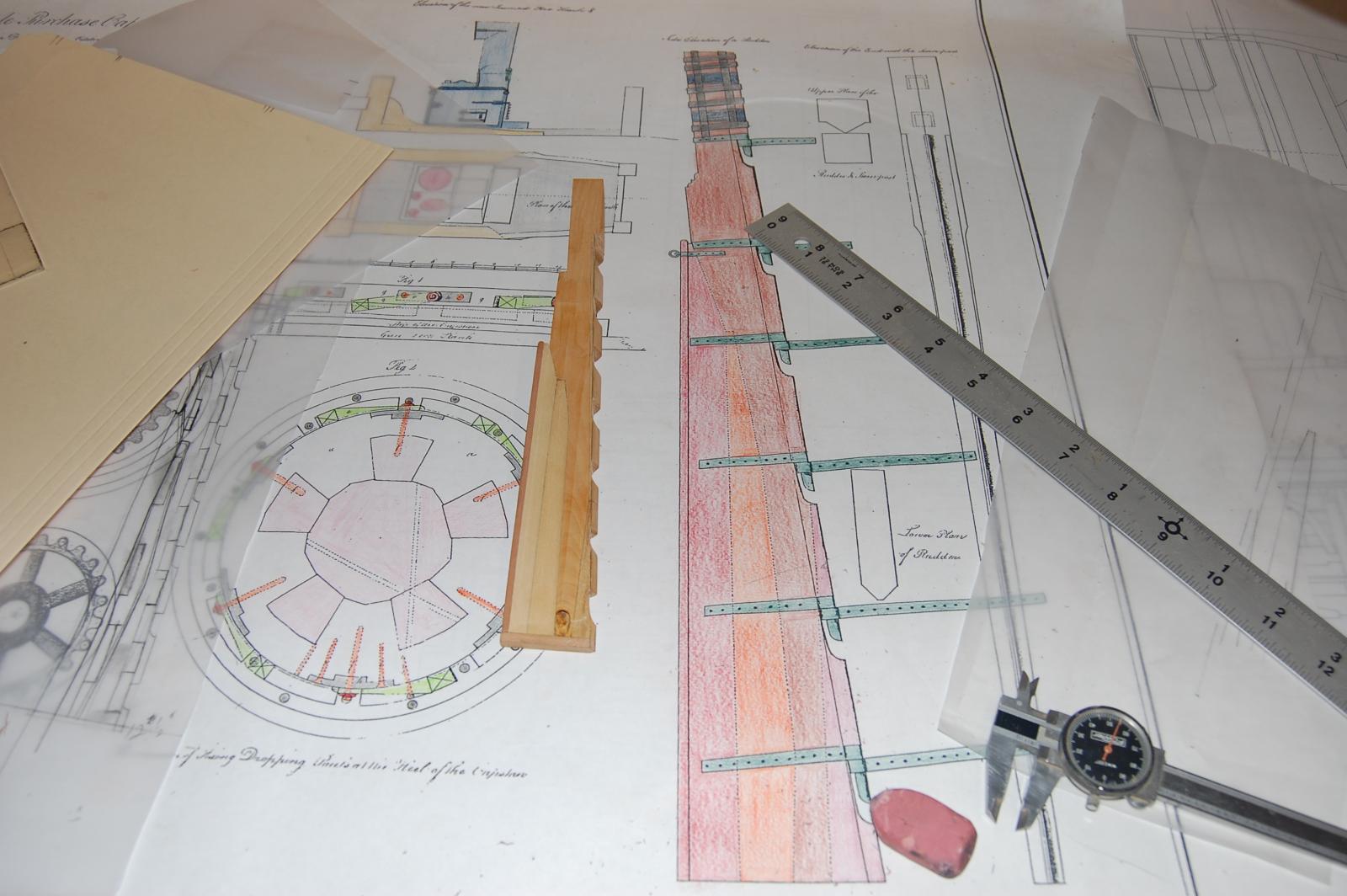
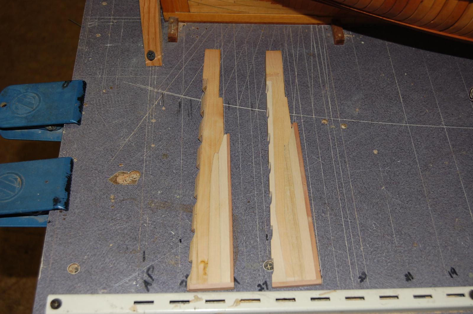
Sort of got tired of working on the cannons so decided to work on something different and this time the rudder. I built a rudder earlier from a plan I got from the NMM and unlike the TFFM rudder this one is a little different. I sort of built two of them and this is the second one. The first one I ended up having a knot in, which the main piece is made of boxwood and figure that the knot would end up in the waste, at least that's what I thought.
 ( O well, it was fun making another one. Have finally got a chance to really use my little smith torch and it's a blessing to have it. Don,t believe that soft solder would have stood up to the abuse of all the cutting, filing and twisting that it took to finally come out with the finally braces. Still have some clean up to do, due to the metal work. Funny how even small metal work makes a mess. Any way hope you enjoy the photo's. I didn't add any small planks under neith the braces and to me it doesn't look to bad.
Gary


- Jeronimo, Blue Ensign, dvm27 and 11 others
-
14
-
Hi Guys and thank you.
Guy,your very welcome sir and glad that you are enjoying the photo's hopfully more will come.
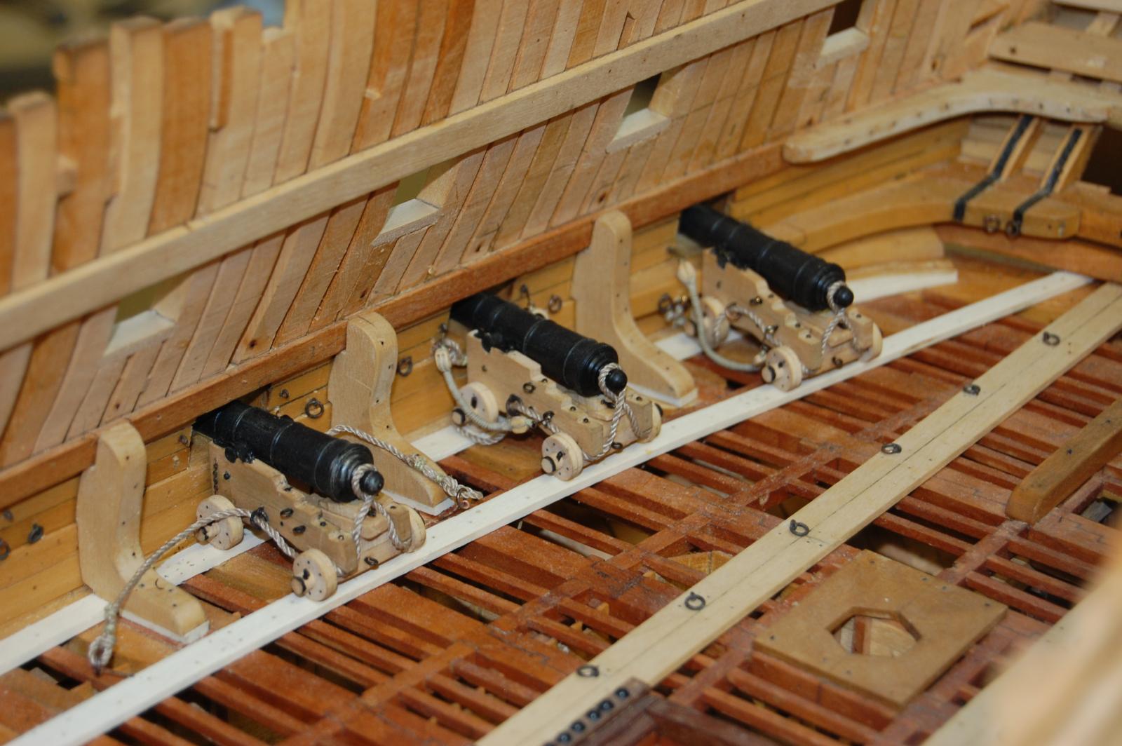
Thank you Chuck,the hooks and blocks are a nice addition to the gun's. Thank you for them and should be ordering some more in the next couple of weeks or so.. Am sure you told me this but can you remind me of what type of metal you used? They seems to have a lot of strength.
YaRus, According to the contracts I have, it gives the height of the orlop deck to the gun deck as being 6 foot 6 inches from the beam of the orlop deck to the bottom of the gun deck planks. The gun deck from the upper deck as 7 feet, which was from the top of the plank of the gundeck to the top of the upper deck plank. The upper deck height was at the quarter deck as 6 foot 9 and at the forecastle as 6 foot 6 1/2 inches which was taken from the upper part of the deck planking to the top of the quarter deck and forecastle deck beams.
Remco your cannon's was a big help sir in the way that you rigged them. Your's gave me some thing to shoot for.
Thanks Brian, do hope she is of some help to you as you build yours. I take it that you are following the practicum by Romero. It does give one good ideal's but I sort of went down a different path of building Montagu. For me I wanted a more accurate Montagu then what you would get using Harold's and Romero to build one. If you have any question along the way let me know sir. I do take it you will be framing it using Harold's type of framing and jig? Good luck and look forward to your build log.
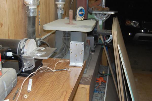
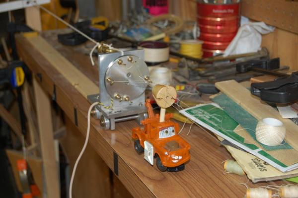
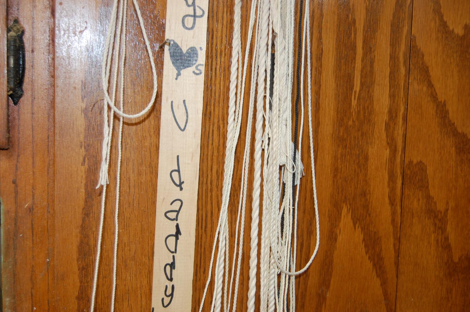
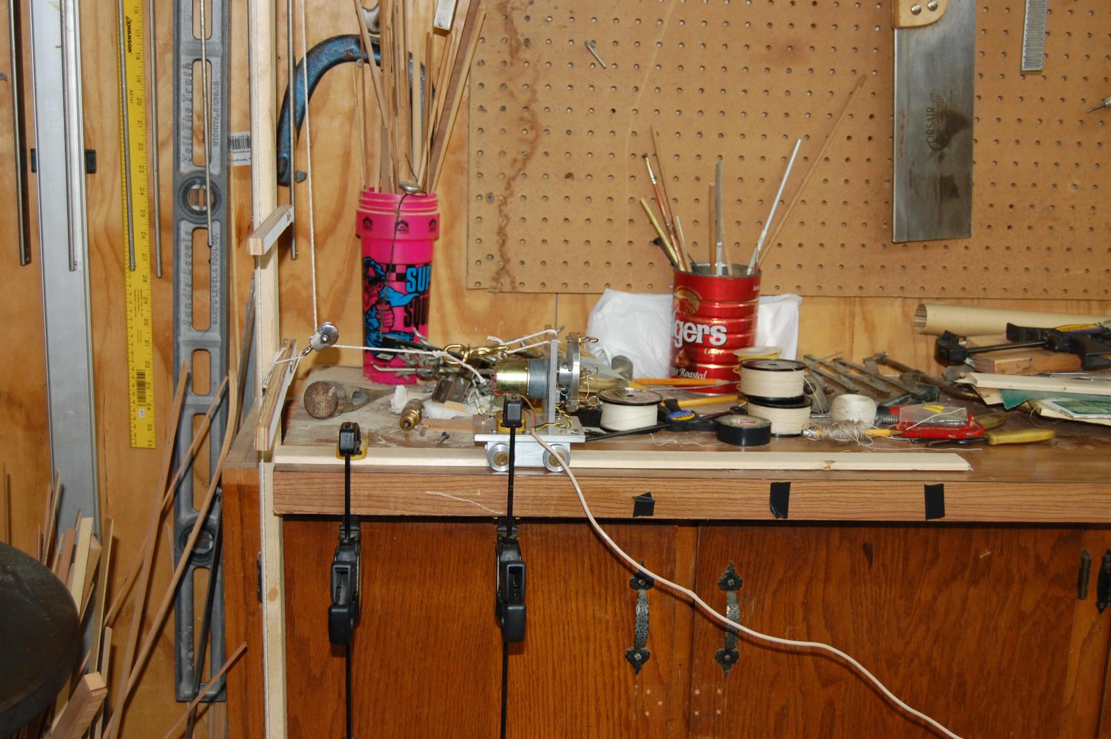
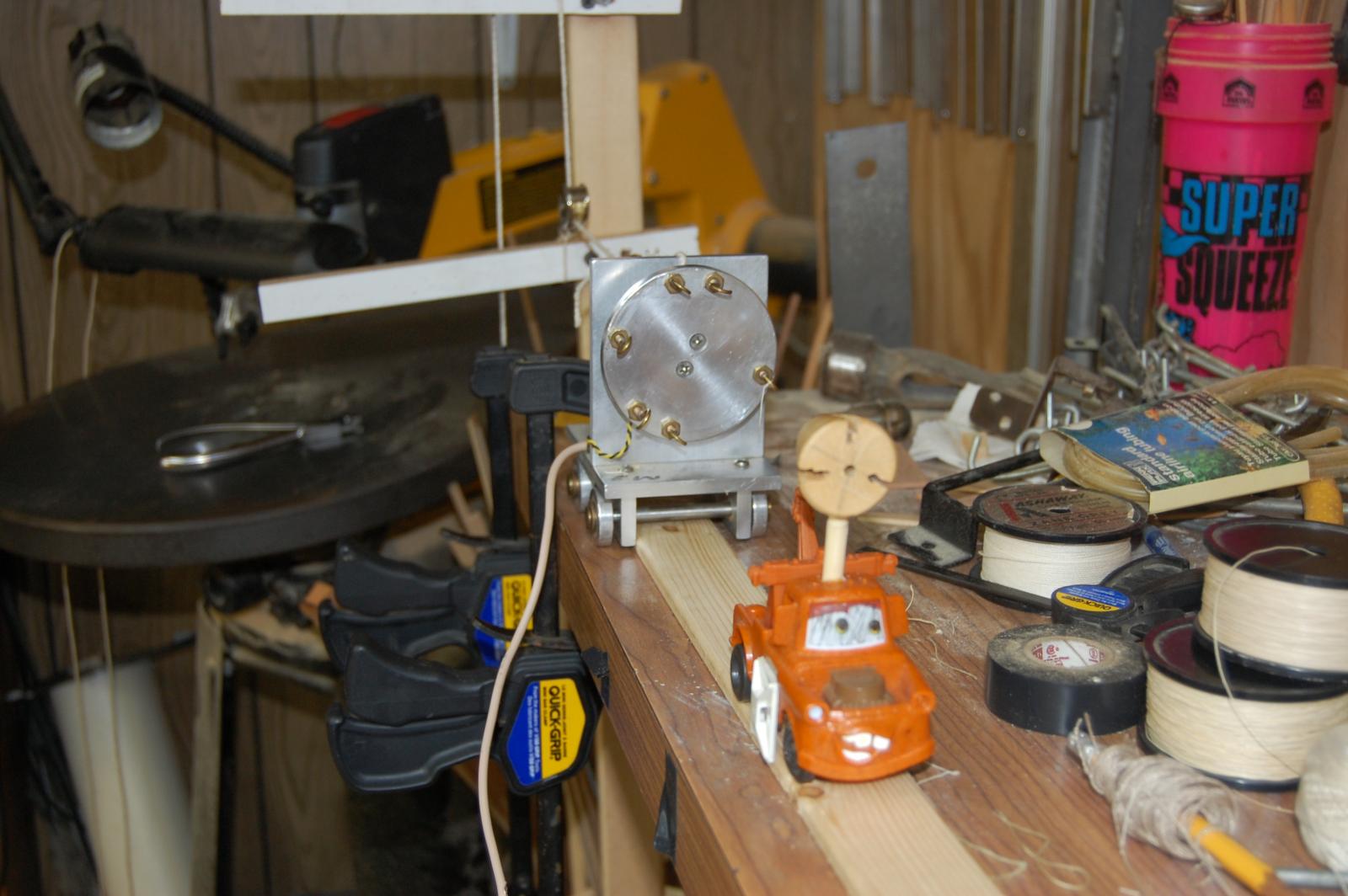
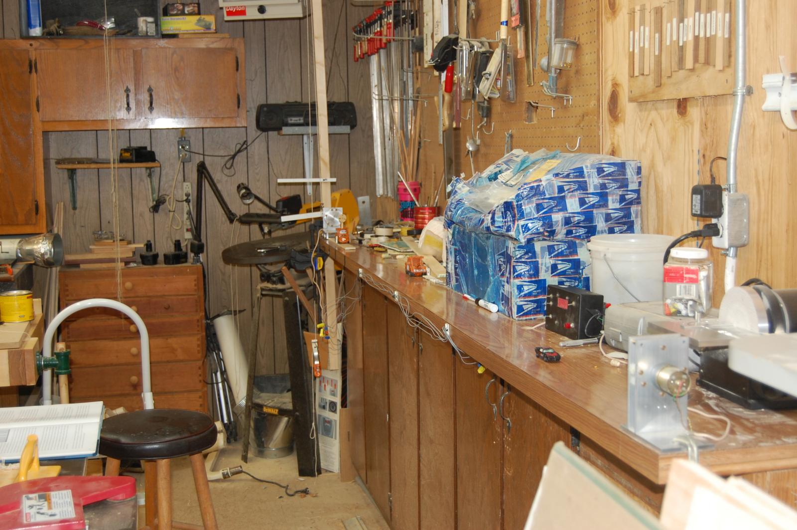
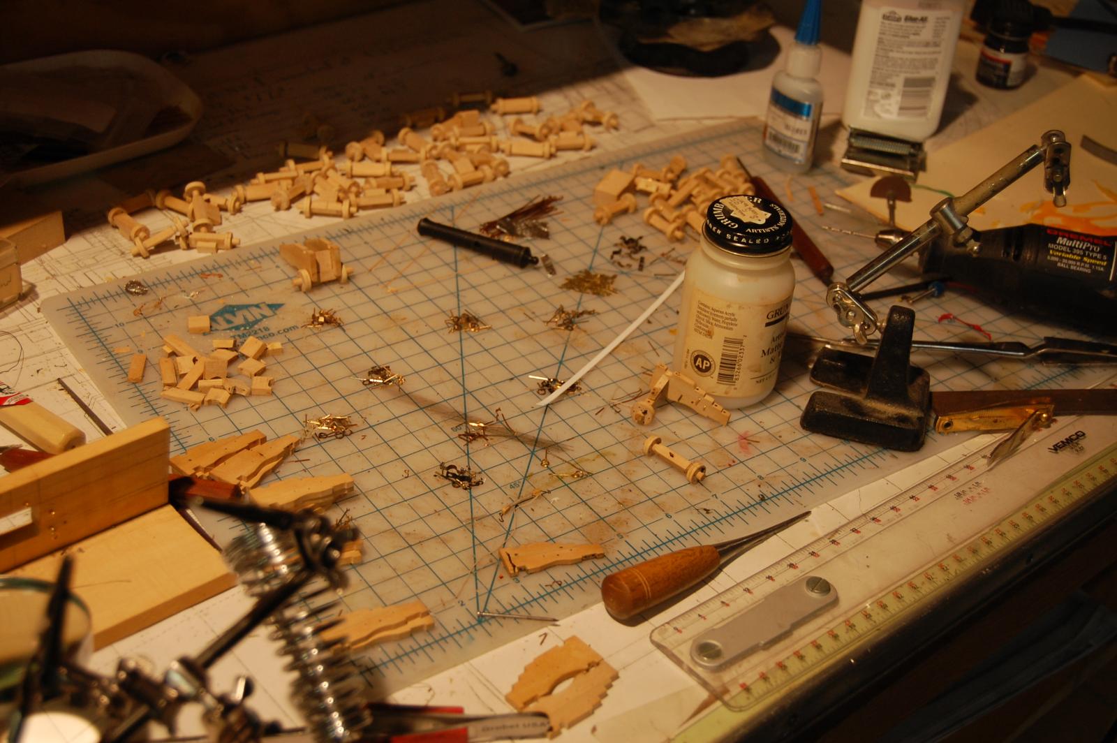
Well folks here is another update on Montagu and this time it's in making rope for the cannons. I have had a rope walk which was built by a good friend, of mine, Tom Nance, and purchased it from his wife after he passed away. It sort of been stowed away until I have had a need for some rope and after spending some time expertmenting I manage to make some rope for the cannons along with the messenger that you saw in the last post. It is based on the same rope walk that Frolick used in his book The art of shipbuilding. Another one of the photo's shows the pile of parts and pieces setting on the work bench waiting to be installed on the gun carriages, that is as soon as I have a little time to work on them. As you can see in another photo, my rope walk can be any length which at the moment is about ten feet long. .
Gary


-
-
Hi Mark. the beeching rope is tucked some what under the cannon itself sir for inspection. That's why the tackles are frapped, that and I think it looks better then having them going to the deck and coiled. Of course there isn't going to be a lot of deck to set things on any way. I just may have to play around with the breeching rope and see how it looks in different position. Gary.


HMS Montague 1779 bygaryshipwright - 74-gun Alfred-class
in - Build logs for subjects built 1751 - 1800
Posted
Merry Christmas Chuck, Michael and to the good folks for the likes. As far as letting the maple oxidize Michael I will sir. Gary.