Hubac's Historian
-
Posts
3,308 -
Joined
-
Last visited
Content Type
Profiles
Forums
Gallery
Events
Everything posted by Hubac's Historian
-
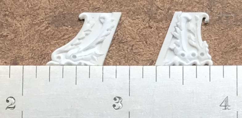
 What I’m thinking about, EJ, are these transitional pieces that ornament each step in the sheer railing:
-
I have a question that is not related to this discussion - more a point of curiosity. This beautiful, old dockyard model of Bellona - even in its interior - appears heavily aged and distressed; much much more-so than your typical dockyard model. Was the distressing deliberate, on the part of the model-maker,do you think, or is the model’s appearance the natural by-product of vigorous handling, over the years? Either way it is curiously different from most other original models I have seen. Apart from that, Mark, nobody could ever accuse you (and Gary) of not doing your due diligence. Fantastic work, as always, and an interesting engineering conversation.
-
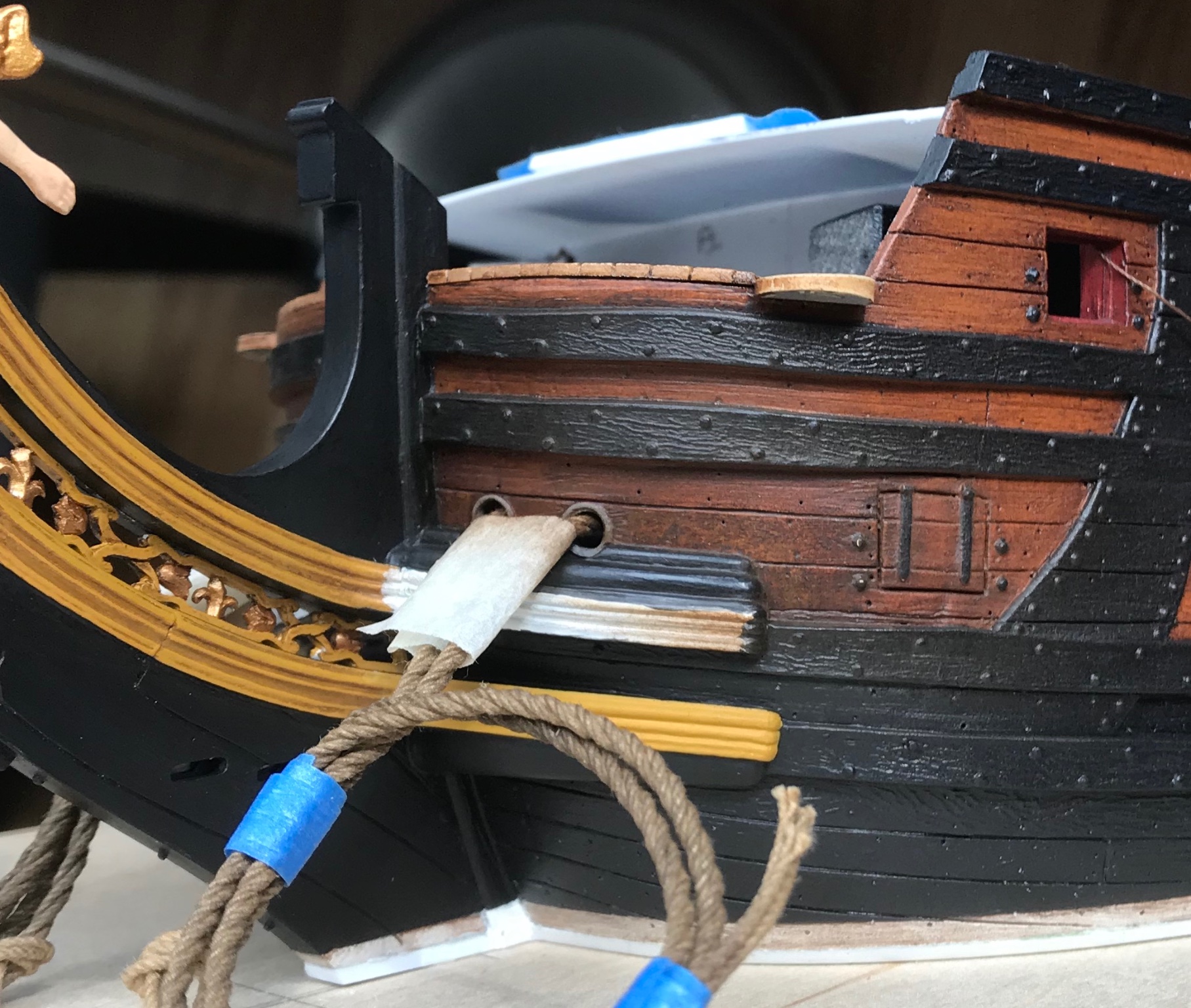
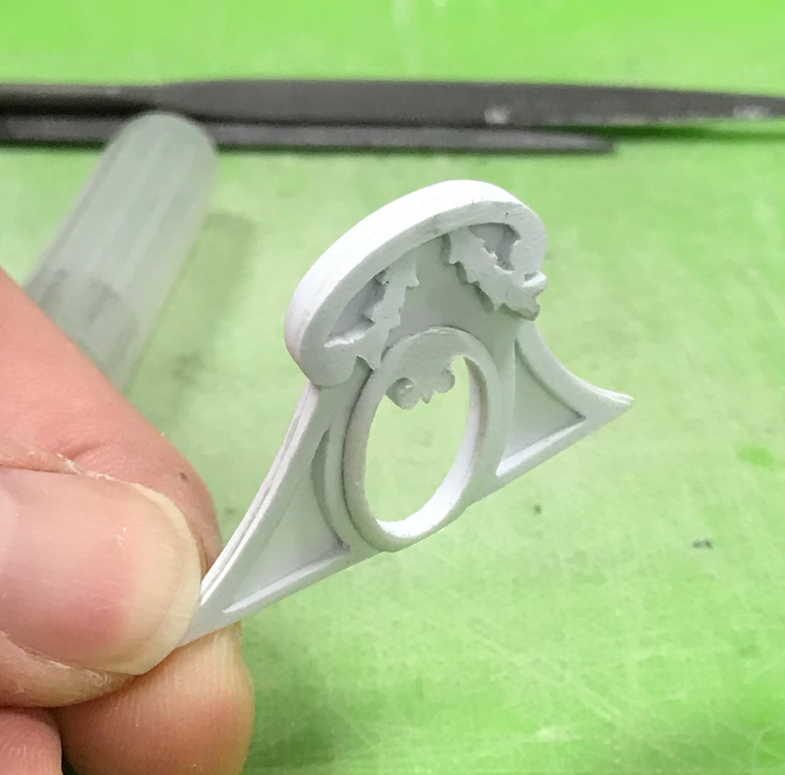
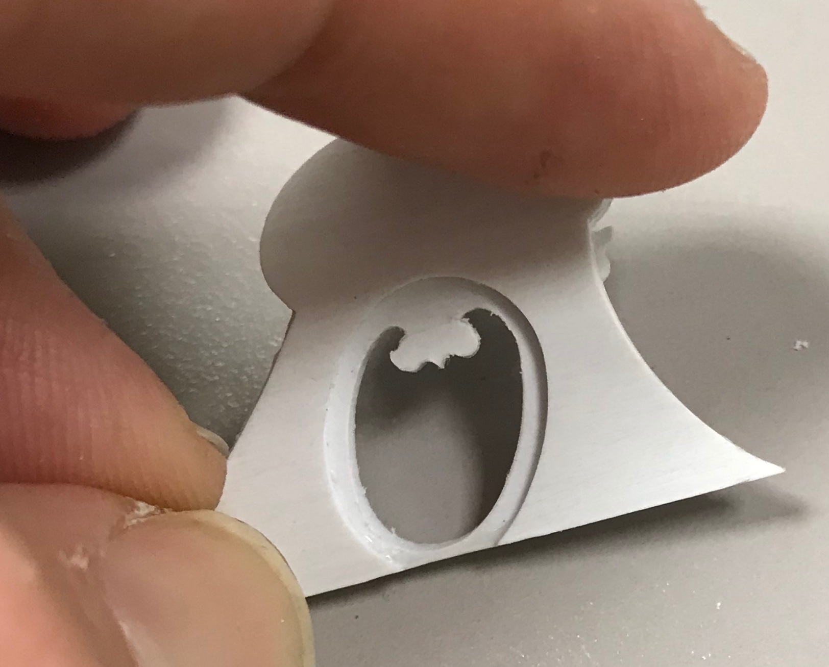
I appreciate the thought, T_C. When I first painted the ship sides, I worked in manageable sections (3-4 port openings), and I only left the oil on the surface for five minutes, before wiping off the excess. This go ‘round, I left the oil on for significantly longer - about 15 minutes - but the contrast was still high after cleaning away the oil, in the darker areas, with spirits. Fortunately, what I proposed seems to have worked pretty well. It will certainly be good enough in this area which is overshadowed by the headrails, anyway. A shot of the stippled effect before blending: Then after blending: Tonight, I’ll resume the yellow ocher. I’ve also been affixing the port side amortisement. I cut through for the octagonal ports and the one real window - the oval of the Admiral’s quarters. This would be moving faster, but I am too nervous about traveling with the upper bulwarks. There is too much time invested to risk damaging them in-transit. In the daytime, I’ve been doing more tedious tasks like cleaning up the kevels. I spent a good bit of time re-reading Henry’s log, today, as I consider how I will run all of my tacks and sheets.

- 2,699 replies
-
- 10
-

-
- heller
- soleil royal
- (and 9 more)
-
Hello, Kevin! Your approach to this kit, and your engineering work-arounds are fascinating. I appreciate your commitment and will follow the project with great interest. You are making a fabulous job of it, so far! All the best, Marc
-
Take your time, Man - she’s coming along beautifully! I’m wondering whether the kit provides fittings for the transitional hance pieces that foot each step in the sheer. I’m not sure if I’m using the correct terminology, here.
-
It has been a slow week of mixed results and some small progress. Painting-in of the head timbers was going well enough. Unfortunately, I over-estimated the blending capability of Van Dyke Brown oil paint to conceal the color-fills I made to the ventre-de-biche of the deadworks. I thought I was being careful to feather-in the new color, yet because of the contrast of the original weathering, I still ended up with a clear line of demarcation: This was after two applications of oil and wiping off the excess. Part of the problem is that the original weathering is sealed under a clear top-coat, so I can no longer lighten or manipulate it. I can only go selectively darker. Toward that end, last night I began applying heavily thinned wash-coats of the oil paint, and have succeeded in eliminating the strong contrast. I didn’t take additional pictures, but the appearance is much improved. At the moment, though, the color appears a bit mottled, as I was applying the color with light dappling touches, over and over again; a brushing motion only “washes” away the color you put down on the previous layer. I then charged the chip-brush I’ve been using with un-diluted oil paint, and left that to semi-cure overnight. My hope is that, this evening, the wash-coats I applied will be sufficiently durable that I can take light sweeping passes with the charged chip-brush to smooth the tone and blend back smoothly into the ship sides. We shall see. In preparation for building up the amortisement on the upper bulwarks, I coped together all of the individual parts, and this helped me feel better about the paint problem. Thank you for looking in, and enjoy your weekend!


- 2,699 replies
-
- 10
-
-
- heller
- soleil royal
- (and 9 more)
-
Thank you, Mark and Jan! Yes, T_C, the forward wing will be inset into the frieze - eliminating a shell - the afterwing, though, lands directly over the aft octagonal port. I will pare that wing away.
- 2,699 replies
-
- 2
-
-
- heller
- soleil royal
- (and 9 more)
-
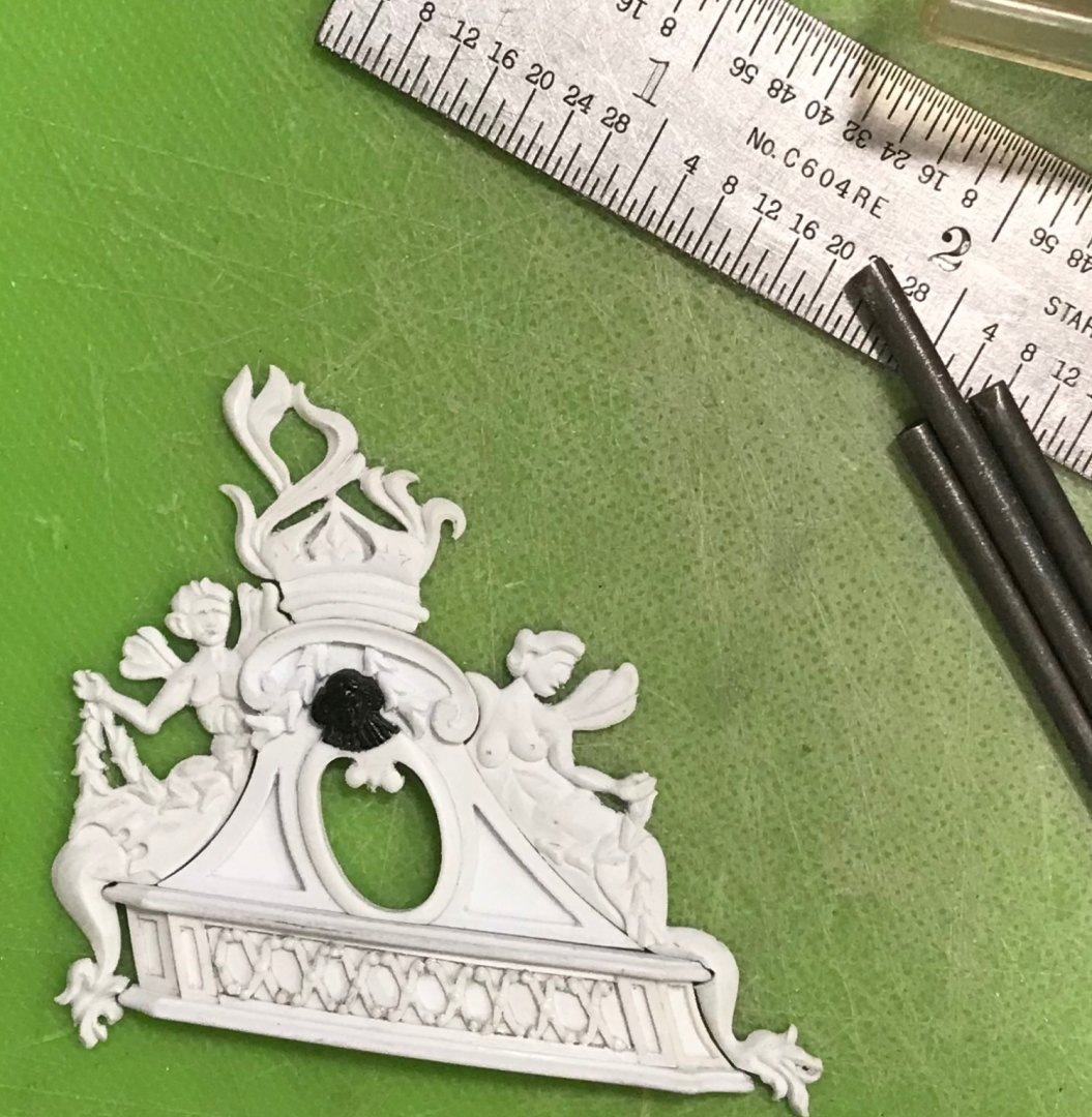
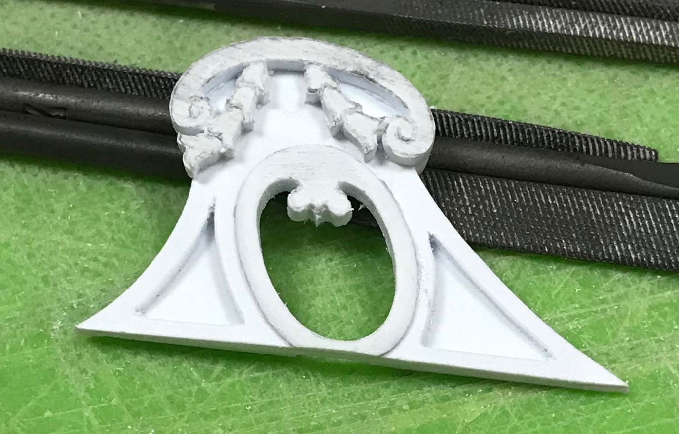
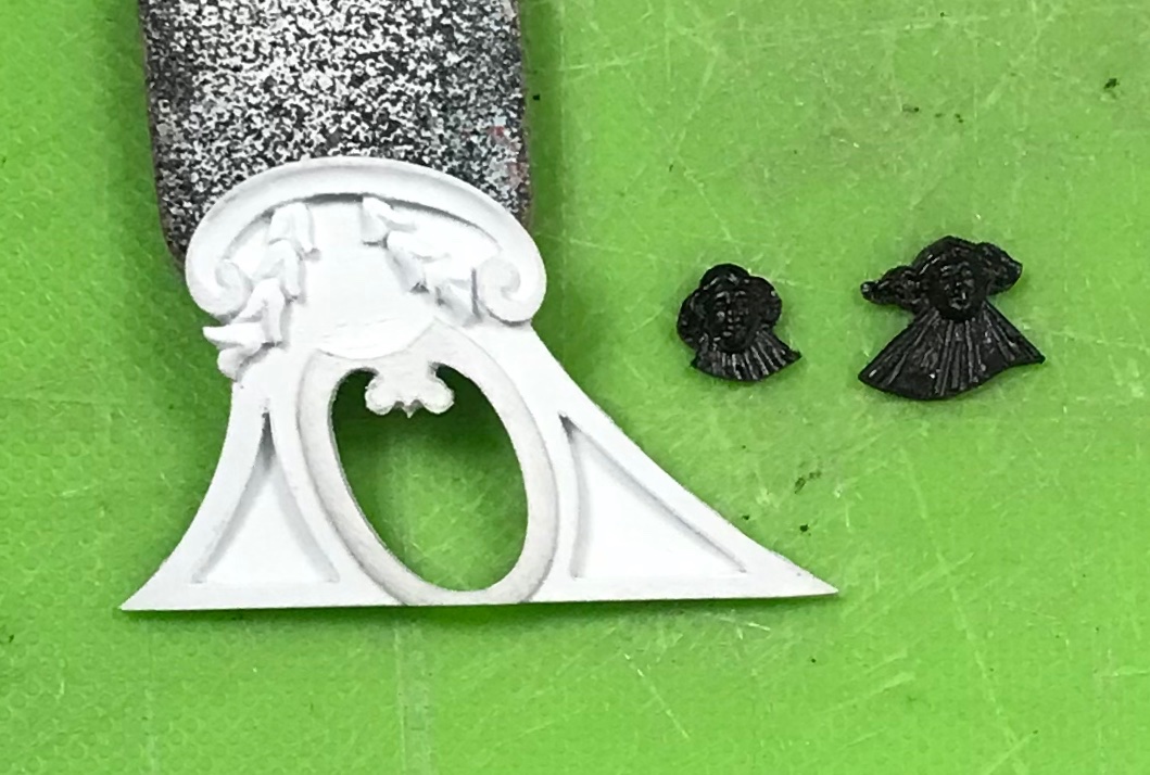
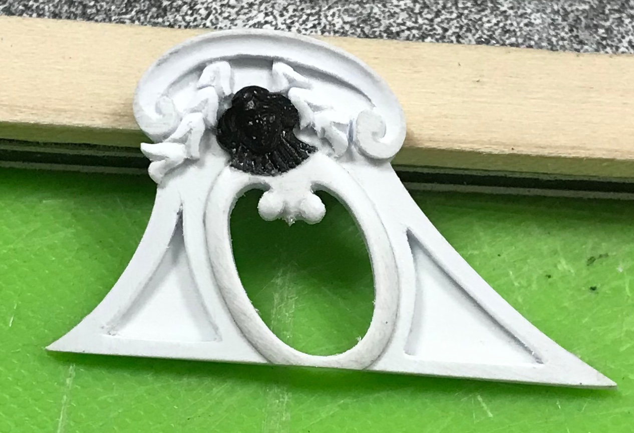
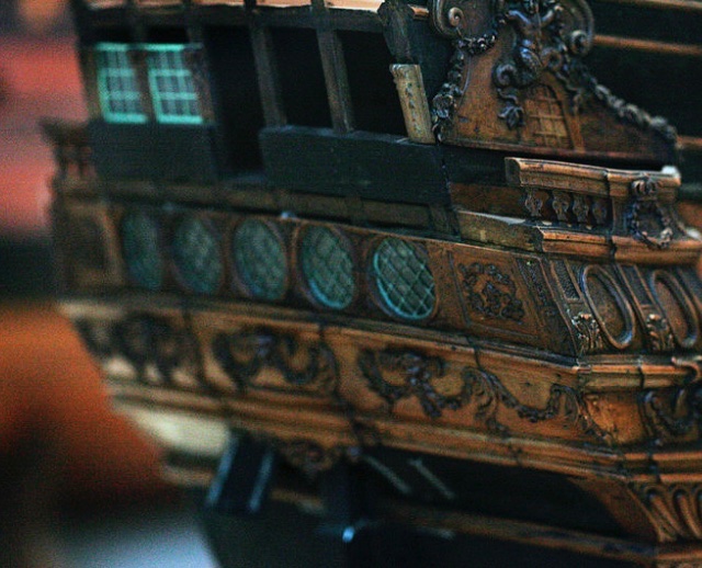
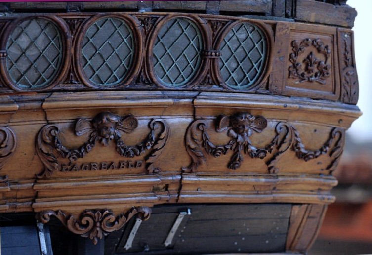
So, the upper finishing of the amortisement has been straight-forward but surprisingly labor intensive. This particular photo of Tanneron’s damaged model of L’Agreable is so instructive because it provides so much information about the fabric of his construction, as well as the shaping cues for the upper finishing of the amortisement: My ambition, always, is to attempt to capture some sense of the magic that makes Tanneron’s models so impressive. Toward that end, it’s a process of layering details with all of the care of execution that one can muster. As has been my method, the upper finishing is made up of a series of laminations: a base layer of 1/32”, a middle 1/16” layer, and a top layer of 1/32”. I toyed with the idea of using Bondo fills to fair panel recesses at a continuous depth. I did not think the Bondo would adhere well enough to the plastic to withstand the slight flex of fixing the part in place. Conventional model putty would be too brittle. In the end, I decided that the 1/16” layer was deep enough to create a sense of shape without having to go through undue effort for minimal gain. I think it worked out pretty well. A montage: Given my struggles to carve good faces, I decided to extract Louis’s radiant head from the same place on the kit’s stock quarter galleries. I wasn’t sure, early on, just how much space I would have left-over, after the bellflower garlands were in place, so I left the heads oversized for the time-being. You can see the subtle shaping of the 1/16” layer, above, as well as the slight rounding of the final window framing. The garland and cornice were a separate 1/16” layer. Just as they are, above, they would be fine, if I decided to stop there. Attention to detail is everything, though, so I took the shaping a little further: The garland diminishes, in depth, as it rises to the cornice, and the cornice, itself, is now tapered in a gentle arc from its center to its ends; this small detail helps to accentuate the convex shape of the windowed center, below. I coved the inner surface of the cornice, modeled the bellflower garlands, and then I gave Louis a haircut. I was able to incorporate just enough of the fanning rays of light, beneath his head, to satisfy the original design: The first layer creates the recess I need to capture the acetate window: I made up the acetate panes, yesterday, but botched the engraving on one, and will have to remake that. So, now that I have all of the elements of the amortisement, it was time to see how this was all going to map out on the upper bulwarks. The whole layout hinges on exact placement of the canopy section. Although the uneven underlying ornament makes it difficult to place these pieces, and the parts have yet to be faired to each other - this placement should enable me to salvage my aft octagonal port: I will have to drop a wing from the forward pixie, but I am now confident that I will be able to make this work. With my kids back in school, and the uptick in their activities, I have found that I am not sufficiently alert, in the evenings, to do good paint work. All of the putty fills at the bow are nicely faired and I brush-primed all of the raw plastic, but I just haven’t felt like I could give it the focus it requires. Opportunity will present itself in the coming days, though. As ever, thank you for the likes and for looking in!

- 2,699 replies
-
- 12
-
-
- heller
- soleil royal
- (and 9 more)
-
I love all that you are doing here, Gary! Your ship is incredible, and your insight, here, and on related logs is very interesting. Personally, I think you really exemplify what the NRG is really about. Awesome stuff!
-
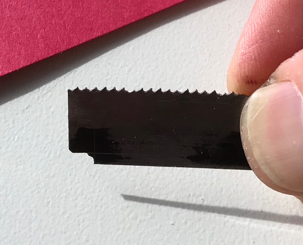
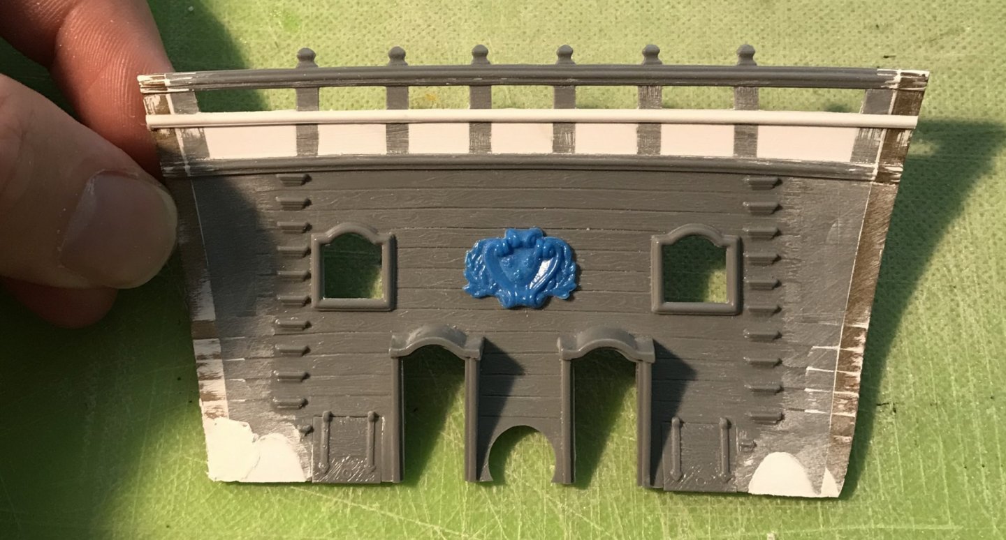
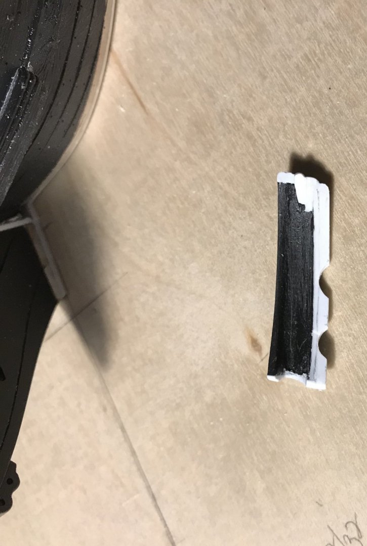
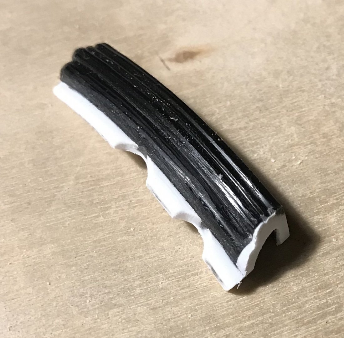
Alright, so I’m pretty psyched with how this all came together: Before glueing on the top and bottom moulding plates, I faired the canopy to the curvature of the upper bulwarks. Now I can simply sand the plates down to match. For this profile scraper, I decided that attempting to scrape the full reverse curve was likely to chatter and dig into the plastic - particularly, along the bottom return. So, I simply ground the top portion of the reverse curve, and then rounded the underside by hand. Now, I can move-on to the upper finishing of the amortisement. That should be a fun little bit of trompe-l’oeil, as I attempt to create a sense of depth in what is now a very shallow platform.

- 2,699 replies
-
- 9
-
-
- heller
- soleil royal
- (and 9 more)
-
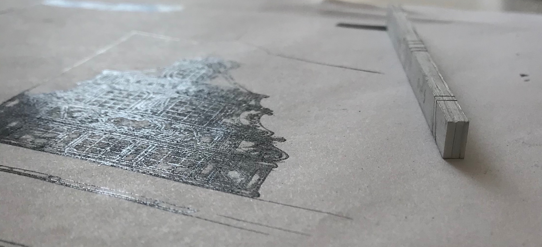
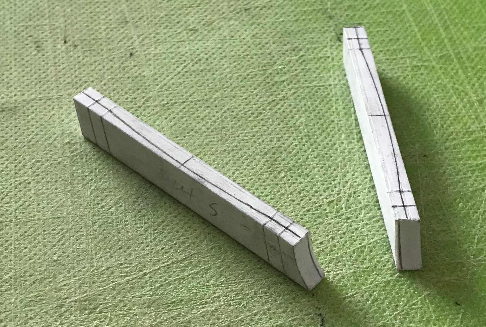
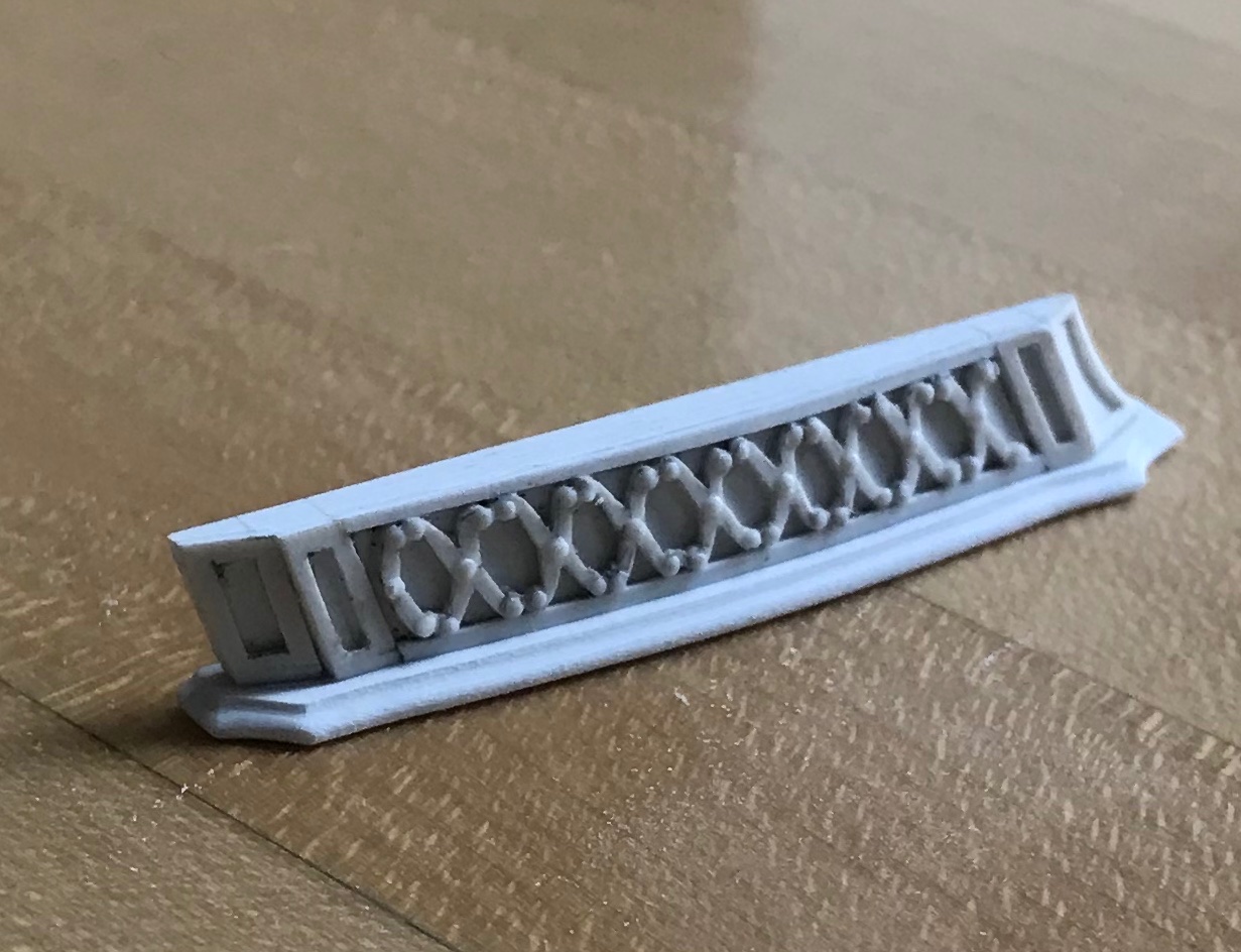
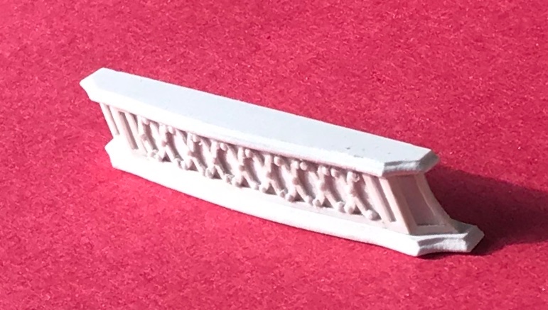
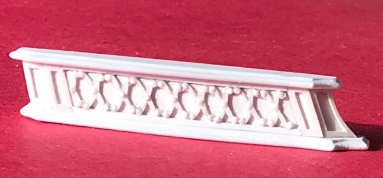
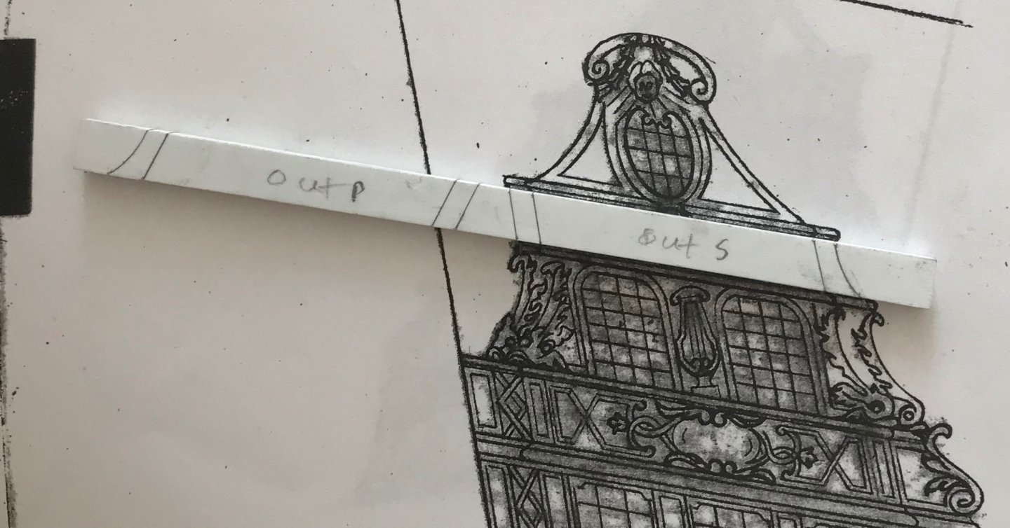
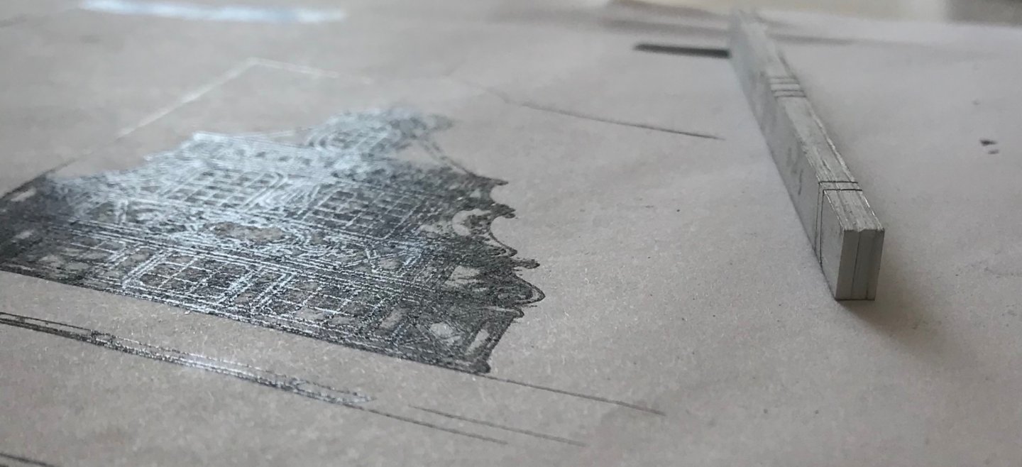
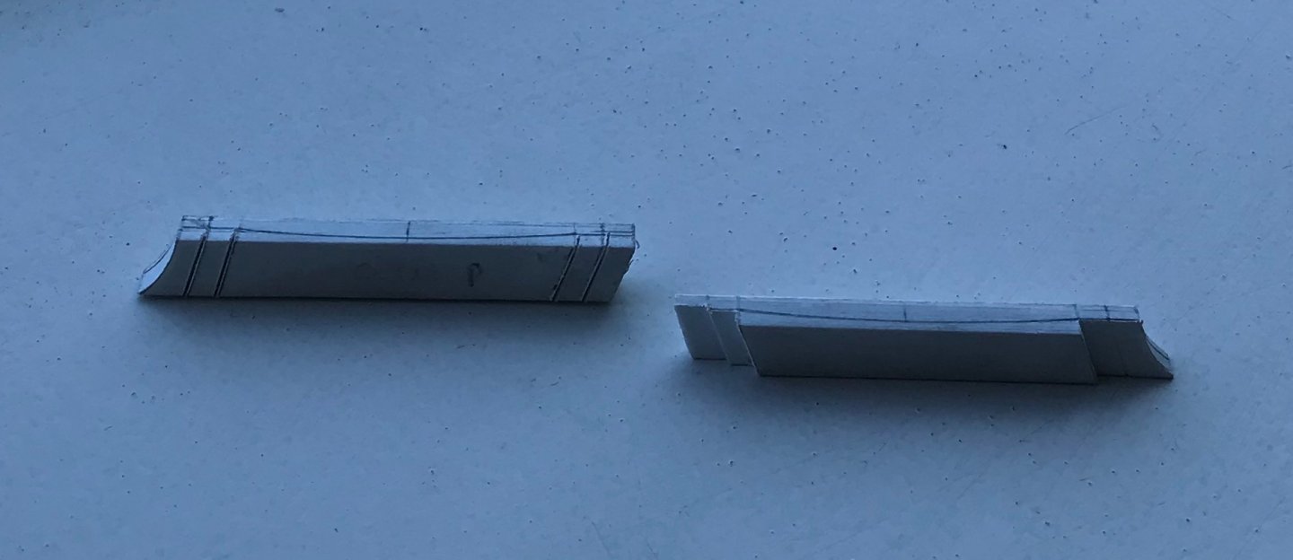
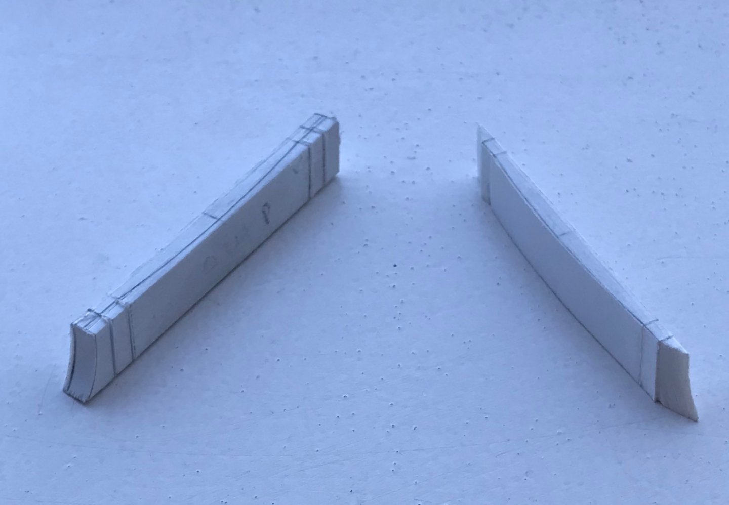
Thank you very much, Victor and EJ! This next level of the amortisement is fun to make because, while it seems simple, it is actually a pretty complex form. Without having drawn a top plan view, I have to wing-it, a little, when it comes to establishing depth and taper. The first step was to make up a styrene billet. The canopy is 1/4” in height, between the top and bottom mouldings. I made my billet stock a little wider, in order to file in the top and bottom taper necessitated by the tumblehome of the ship’s sides (see pic below). Once I had billet stock, I could lay out all of the paneling and the outer parameters of the canopy: The tricky thing about this aspect of the project is that there does need to be some depth to the canopy - which will be further overhung by the top and bottom mouldings - because the upper-most section of the amortisement has at least some depth, at its center, which tapers out to the sides (where they abut the pixies). Considering that, the canopy must also diminish, slightly, in depth, from top to bottom. And, on top of all of that - there are a series of reverse curves that define the bombastic form of the canopy. In layout, and looking at it from the top view, that all looks like this (excepting for the reverse curves, at the ends, which I did not draw-in): With the layout pencilled-in, top and bottom, and on the outer face, I could then make a series of shoulder cuts, with a fine back saw. After hogging out the bulk of waste, at the ends, this is what that looks like: Once all of the shoulders were neatly defined, I could set-to shaping the subtly curves ends and middle: The end scallops are set-down about 1/32” lower than their adjacent short flats, so that when I apply the panel framing details, in the next step, there will remain a stepped demarcation between the ends and middle section. As I had hoped, the second Xs moulding came out much more cleanly than the first. These decorations are springy enough to accommodate the tapering surface, without appearing to become distorted. Once, I have the port-side canopy made and both canopies paneled, I can use them to pattern the exact top and bottom overhang of the mouldings. More to follow...

- 2,699 replies
-
- 9
-
-
- heller
- soleil royal
- (and 9 more)
-
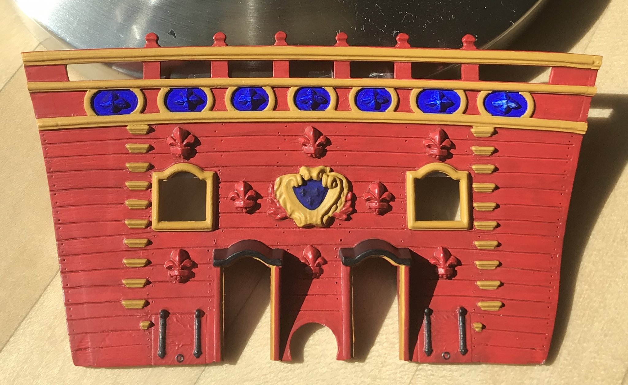
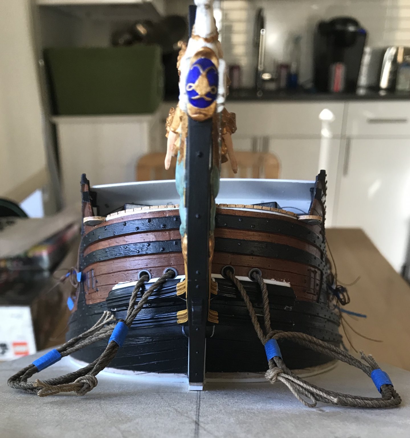
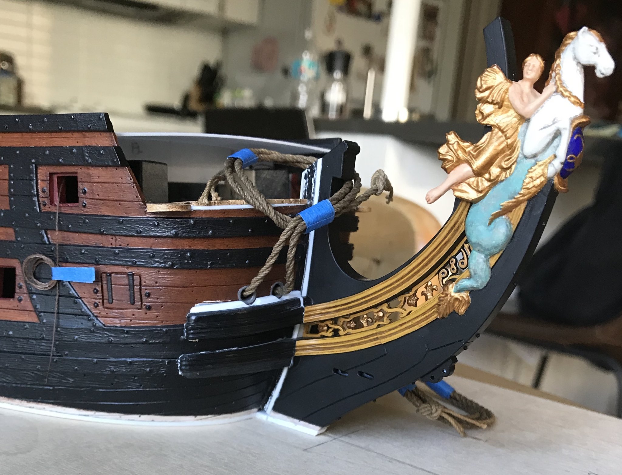
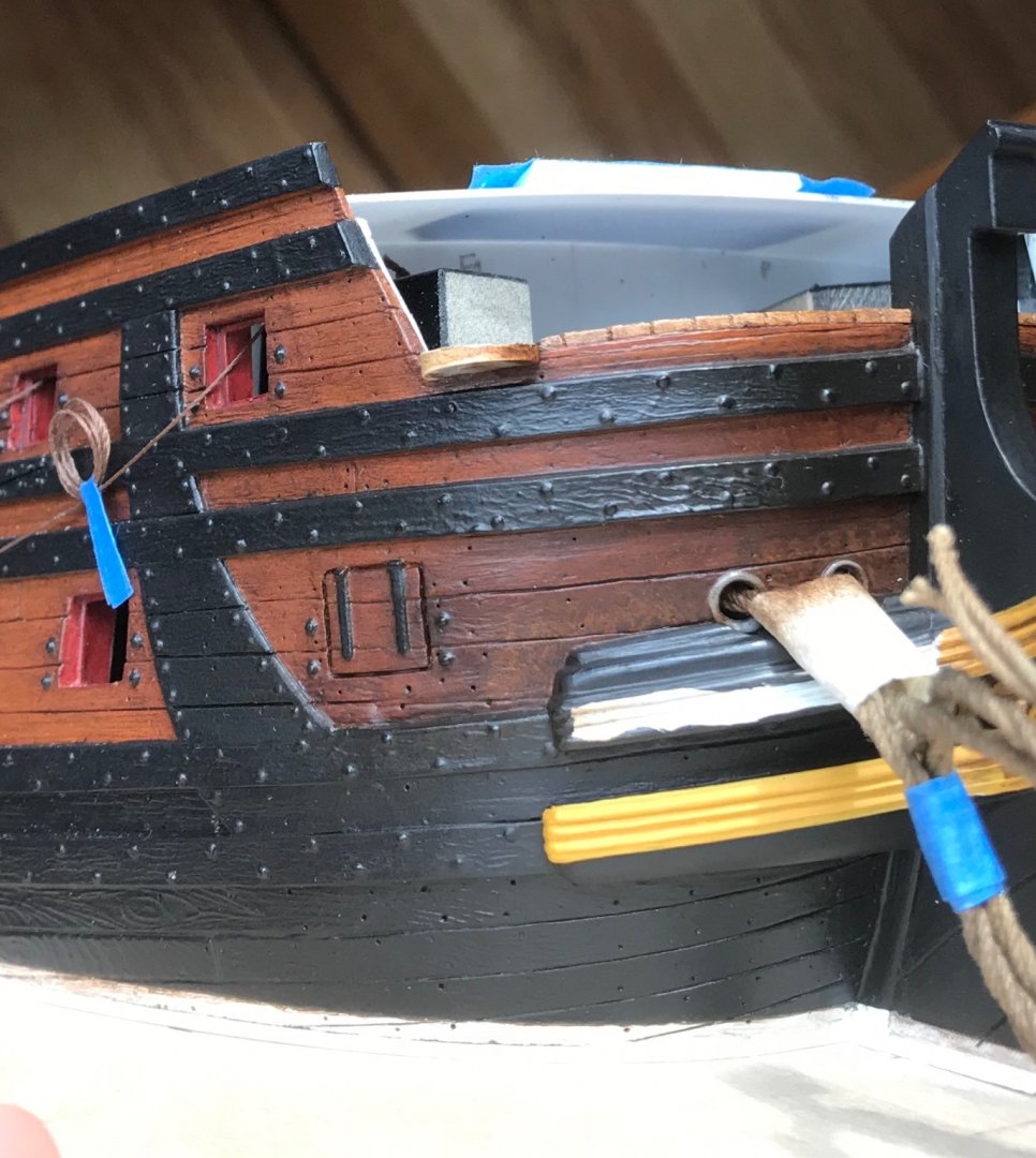
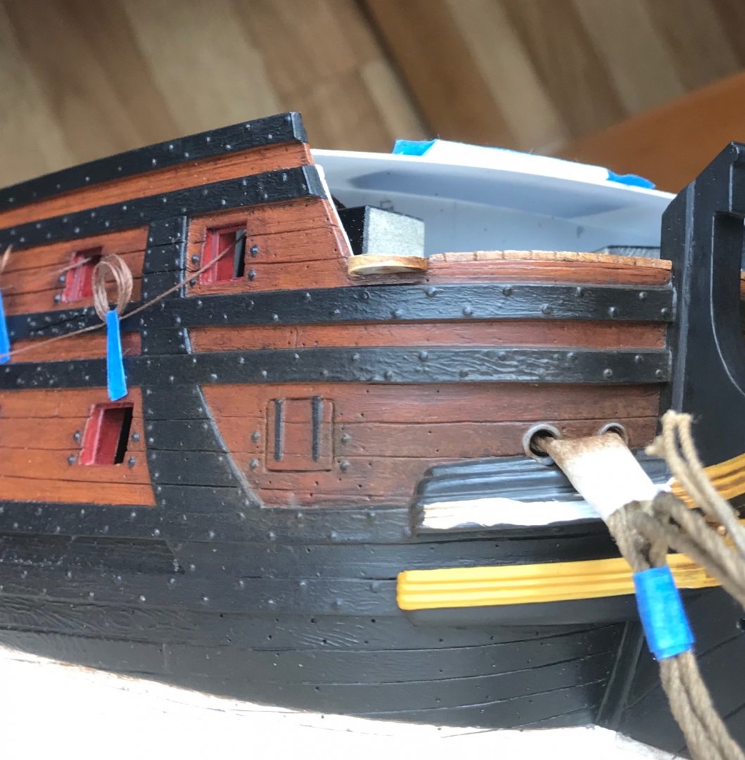
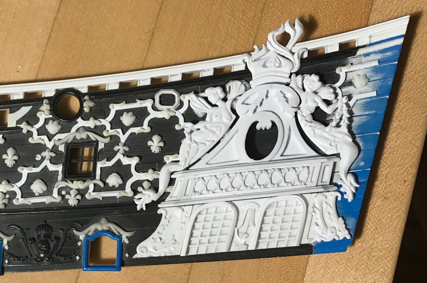
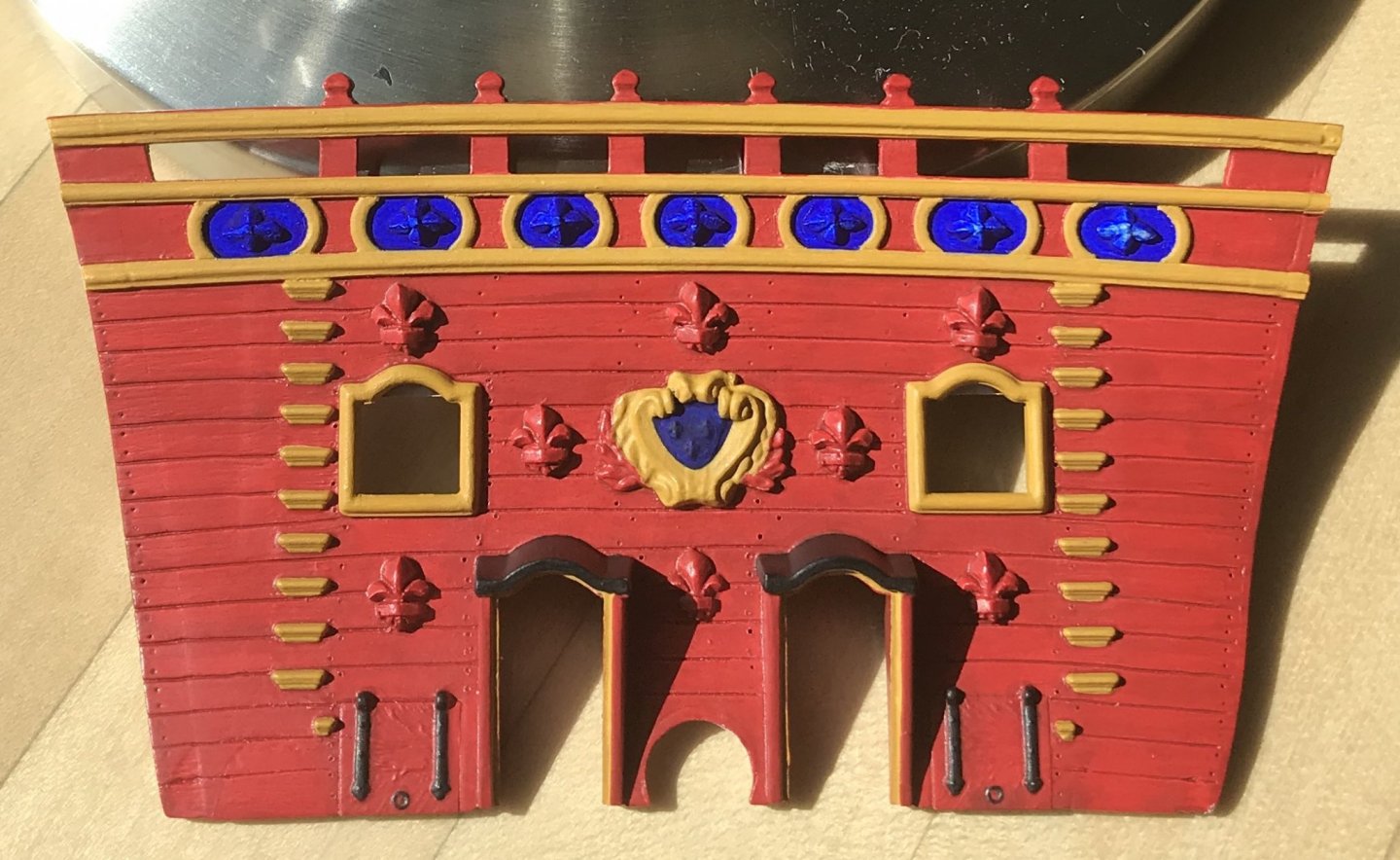
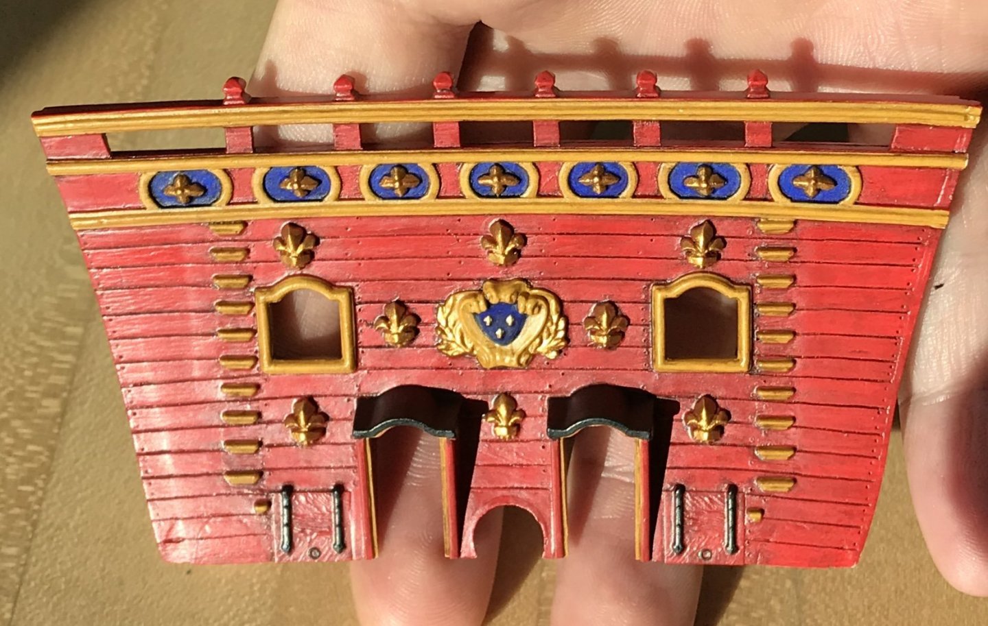
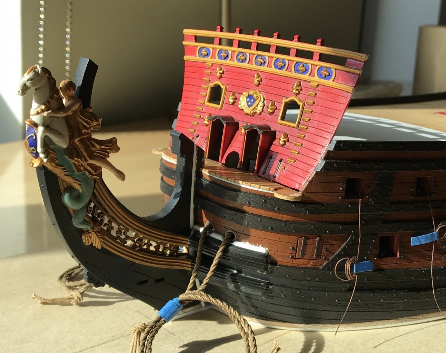
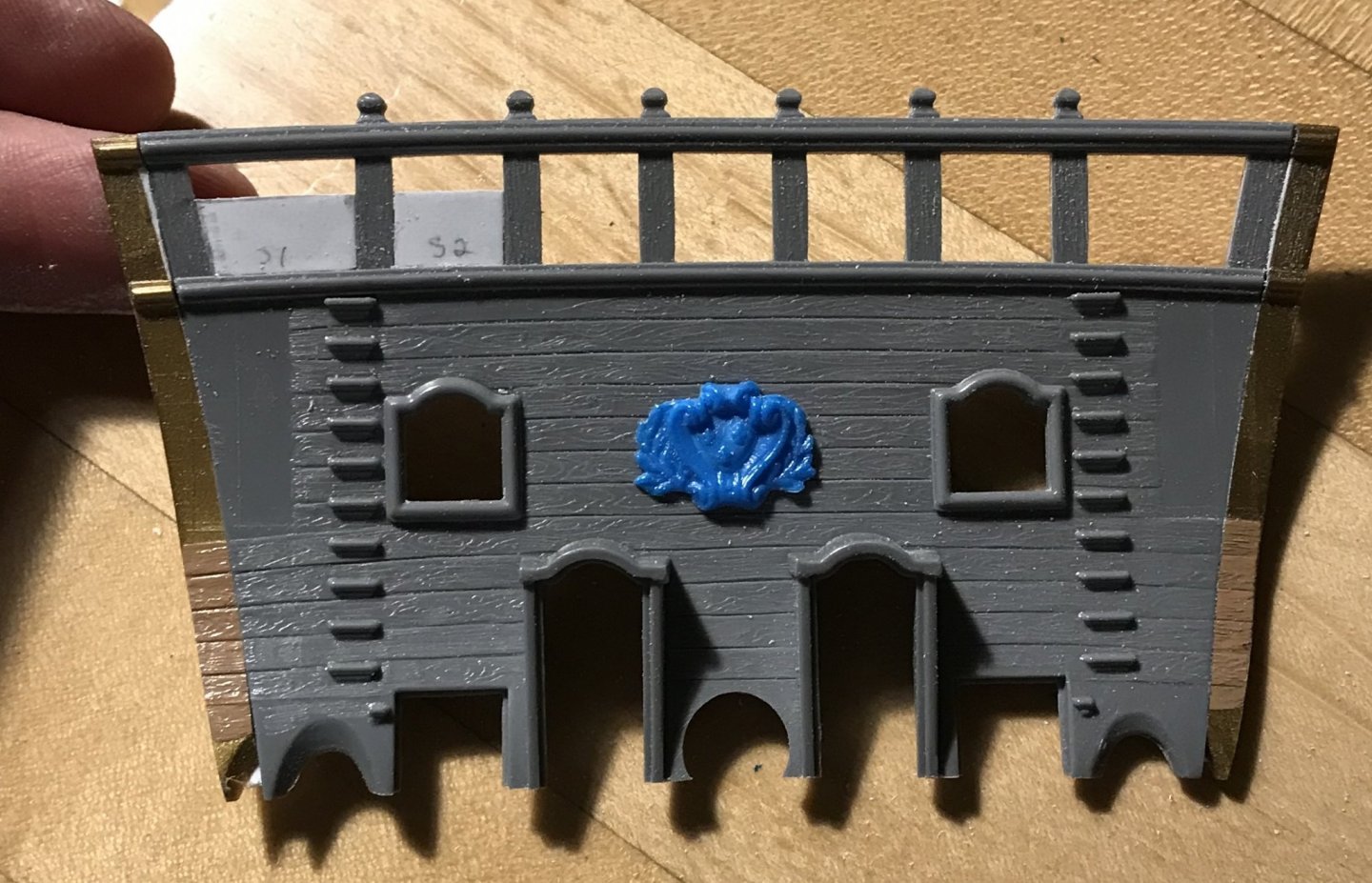
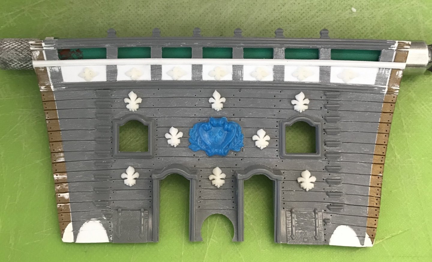
The beakhead bulkhead is painted, now, and ready for installation. Before I do so, though, I will do a little addition to increase the glue surface area, backing the bulkhead. I decided at the last minute to add panel framing around the foliate diamond ornaments. It echos, if not exactly, panel framing around the lowest tier of fleurs on the upper bulwarks. I didn’t really have the necessary space to copy this, so I simplified the paneling. In fact, I originally wanted to use fleurs, but I couldn’t reduce them enough to make it work. Even the smaller fleurs that I made for the stern counter were too big. So, here’s the paint work bright and clean, as on the first day of her re-launching in 1689/90: And here is two years of sea grime and paint oxidation, as just before the battle of Barfleur: The blue, here, is really a cobalt blue, but it deepens to the ultra-marine with a very light wash of walnut ink. The first red acrylic I applied was a proprietary mix for BLICK art supply. The color was lovely, but I soon discovered that the paint would wash away when wetted. I’m not sure why that is; perhaps, in thinning the paint with regular tap water, I altered its curing properties. Anyway, I washed away the paint with soap and water and then applied ModelMaster’s Insignia Red acrylic, which is the red I’ve been using everywhere else. I can successfully thin this formulation with tap water. It turns into a pleasing red ocher, once the walnut ink is applied. The other decision I had to make was whether to paint the top sheer of drift rails gold or yellow ocher. I decided, ultimately, to go with the yellow ocher, and to save gold for the ornaments, themselves. Thanks for the likes, comments and looking in!
- 2,699 replies
-
- 19
-
-
- heller
- soleil royal
- (and 9 more)
-
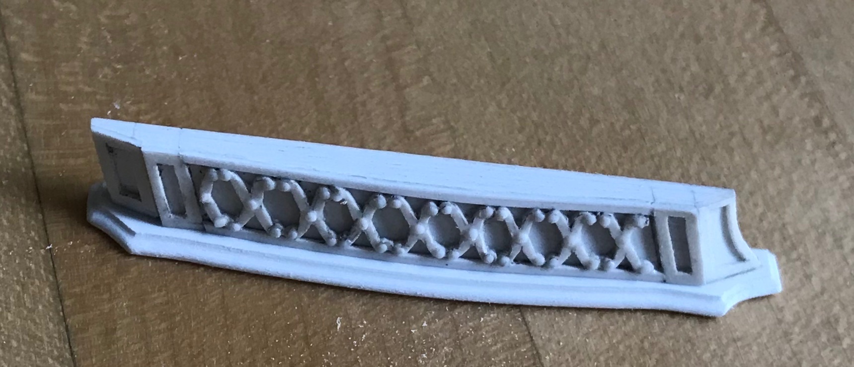
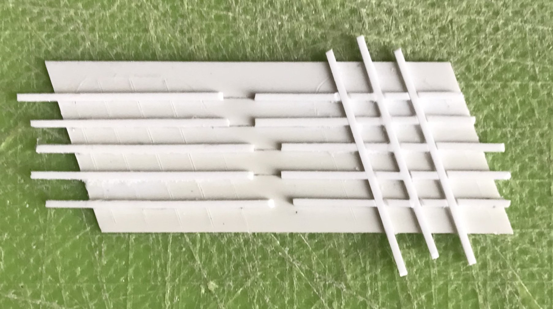
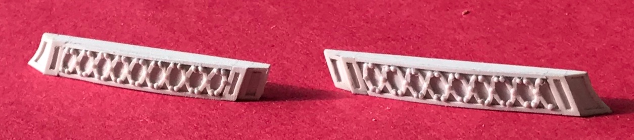
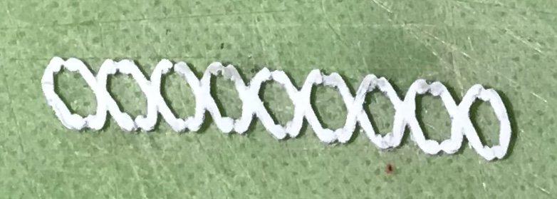
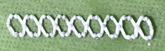
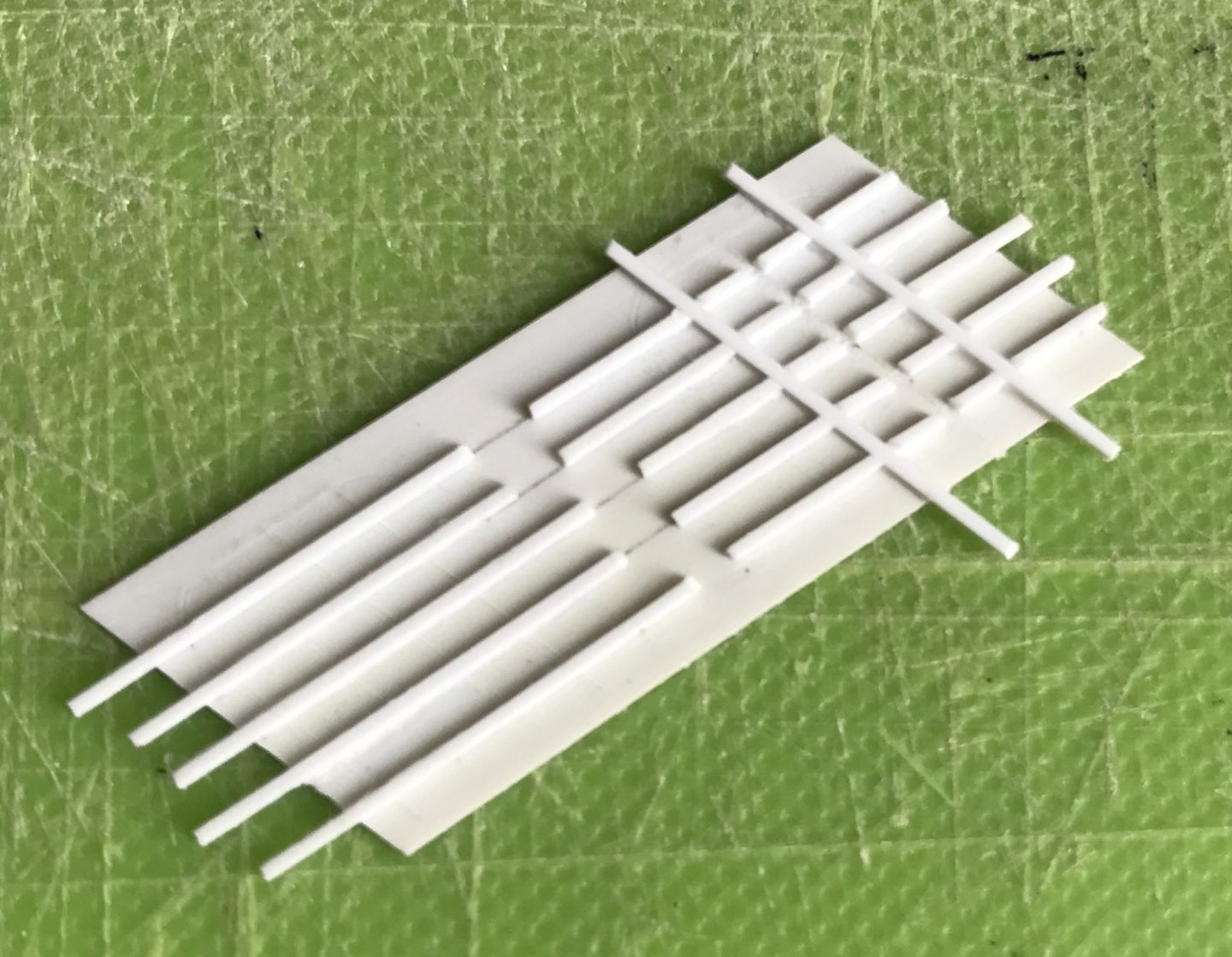
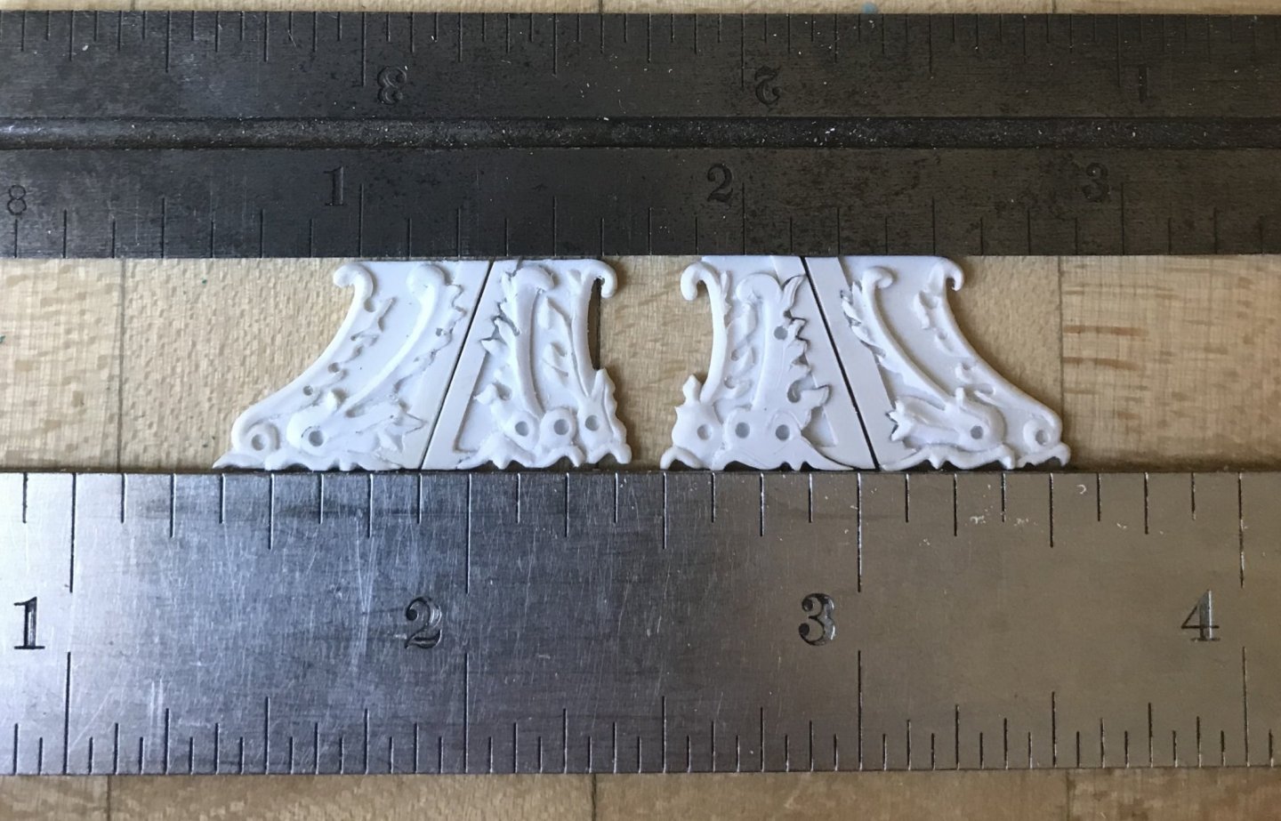
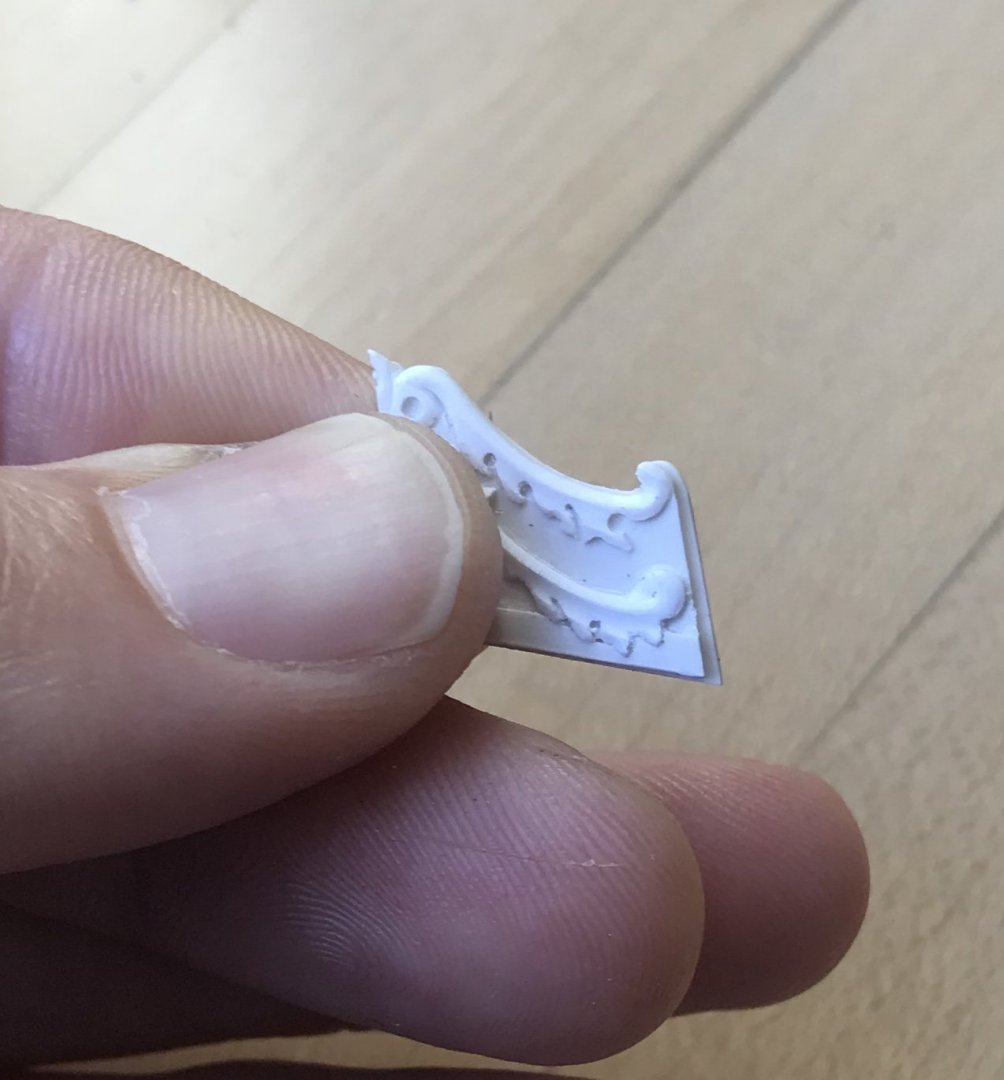
Thank you, Victor - Little by little, we are getting there! I made this - I’m not sure what to call it - Xs ornament for the starboard side. Even more so than the trailboard, this thing is terribly small and impossibly fragile. This turned out okay. The first effort was a disaster and had to be scrapped; a lighter touch and a pointier blade produced much better results. Still, though, the extensions of the Xs don’t have the neatly uniform rounding I was hoping for. I decided to add tiny domed slices of styrene rod to dress it up a bit, and give the whole thing some dimension: I think this helps. Once it is straightened out and secured to its backing it will look plenty good enough. The port side should turn out better, now that I know what I am doing. The beakhead bulkhead is painting up really nicely, and it will provide an exciting (for those who get excited about these things) glimpse into the eventual coloration of the stern. More on that to follow. Enjoy your weekend, everyone!
- 2,699 replies
-
- 7
-
-
- heller
- soleil royal
- (and 9 more)
-
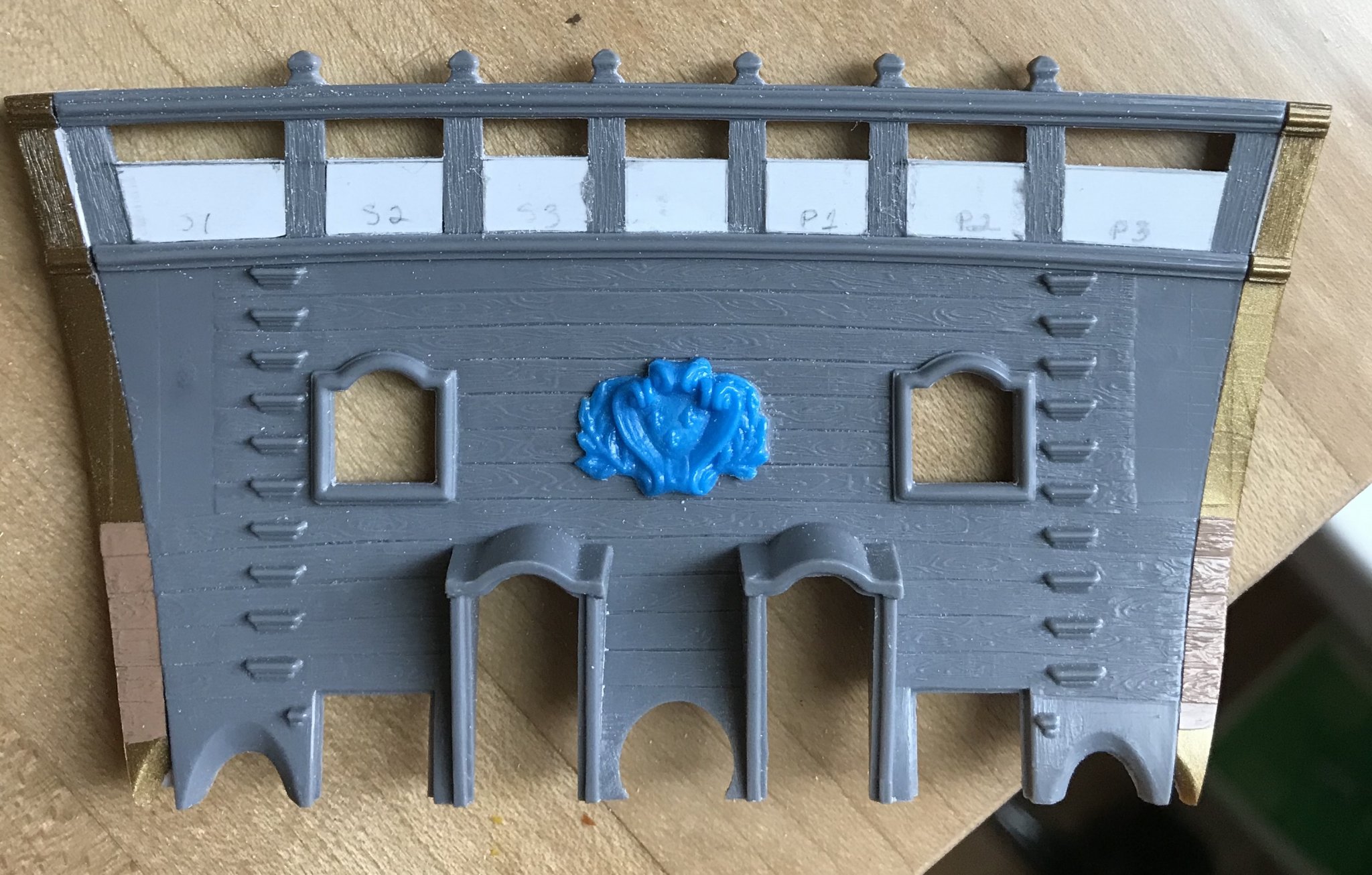
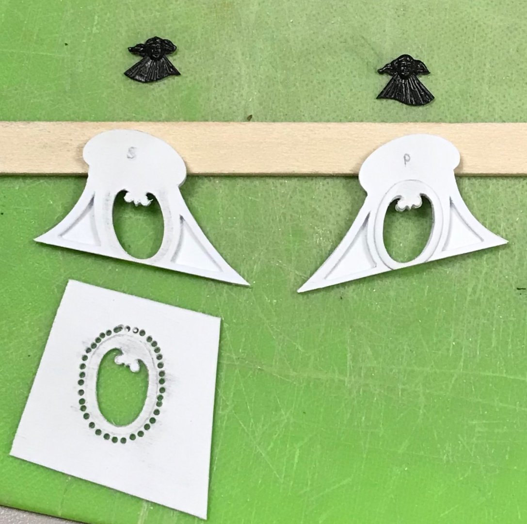
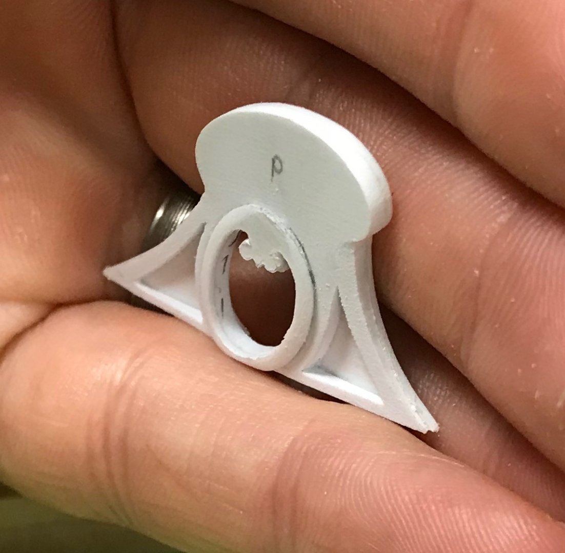
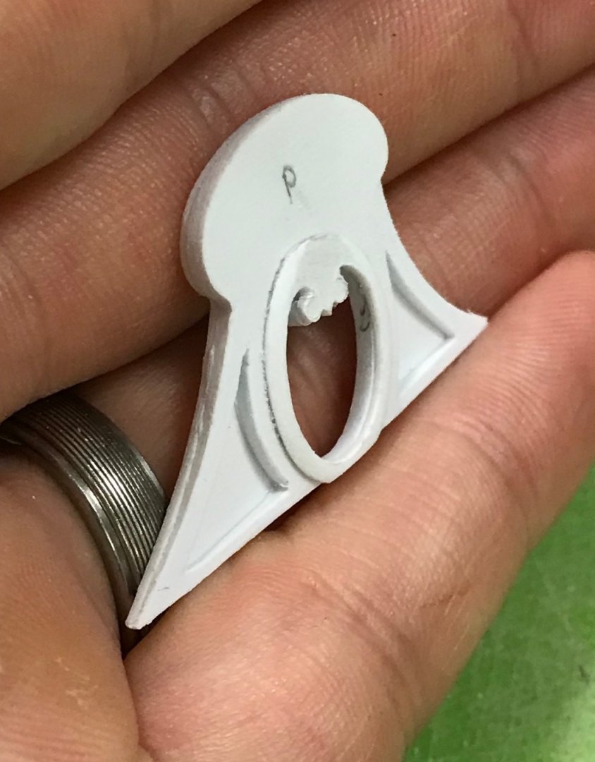
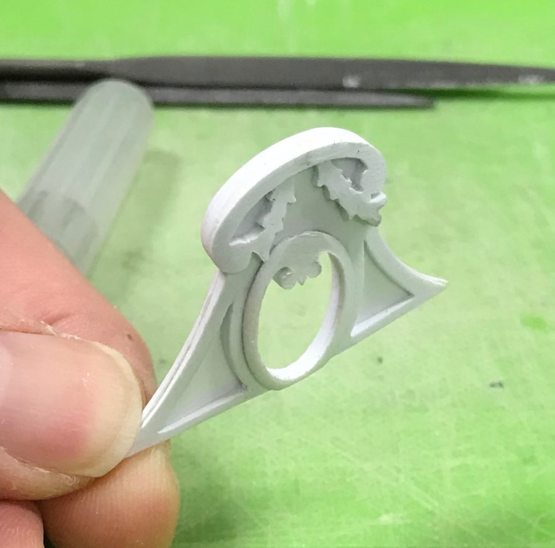
I appreciate the compliment, Mark! Well, with the harps made, the windows are now complete, and I’m about 60% of the way, done, with the amortisement. Final assembly will take some finessing, but here is what we have so far: Next up, I will tackle the semi-structural elements above the windows. Thanks for the likes and for looking in!

- 2,699 replies
-
- 13
-
-
- heller
- soleil royal
- (and 9 more)
-
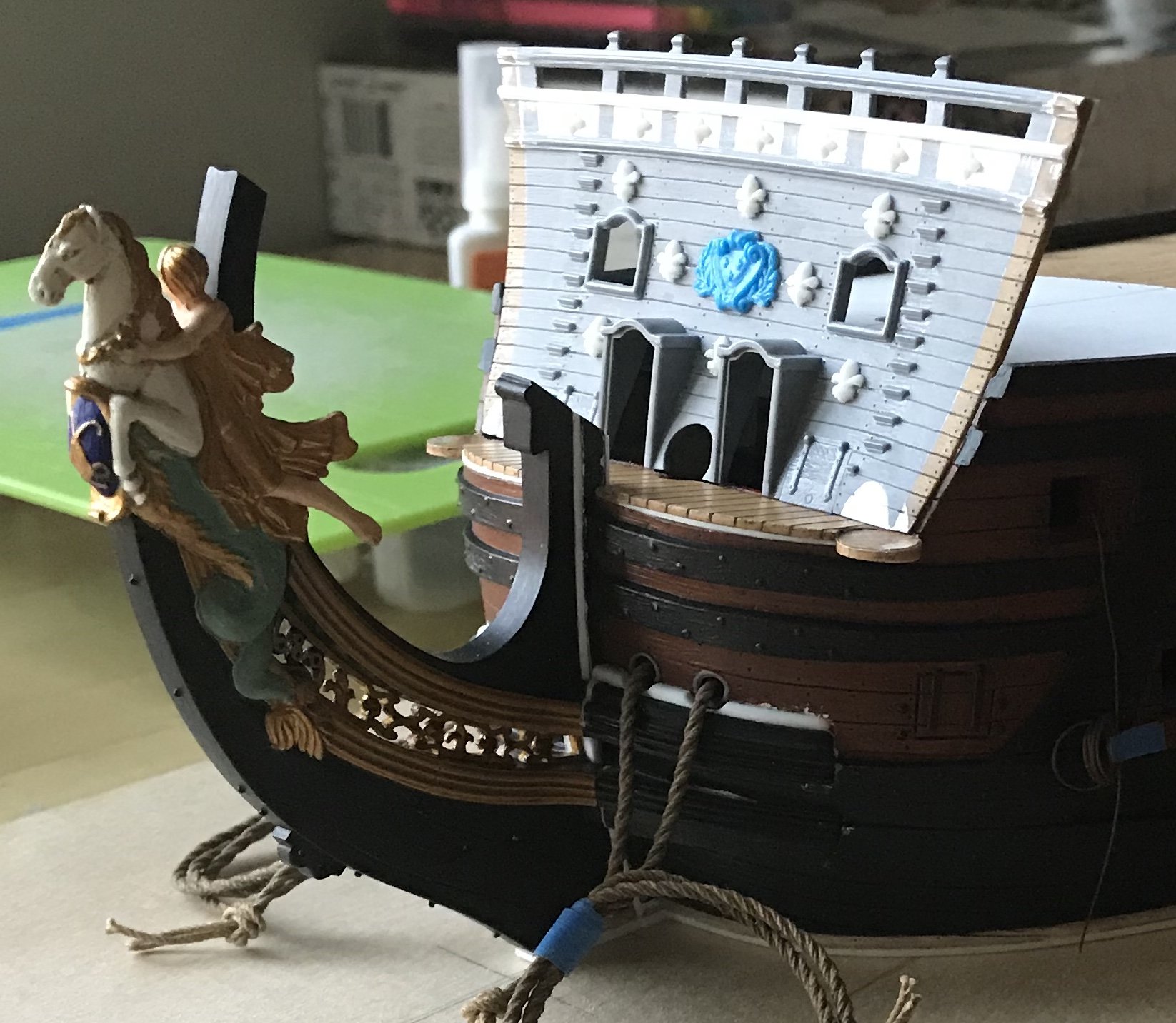
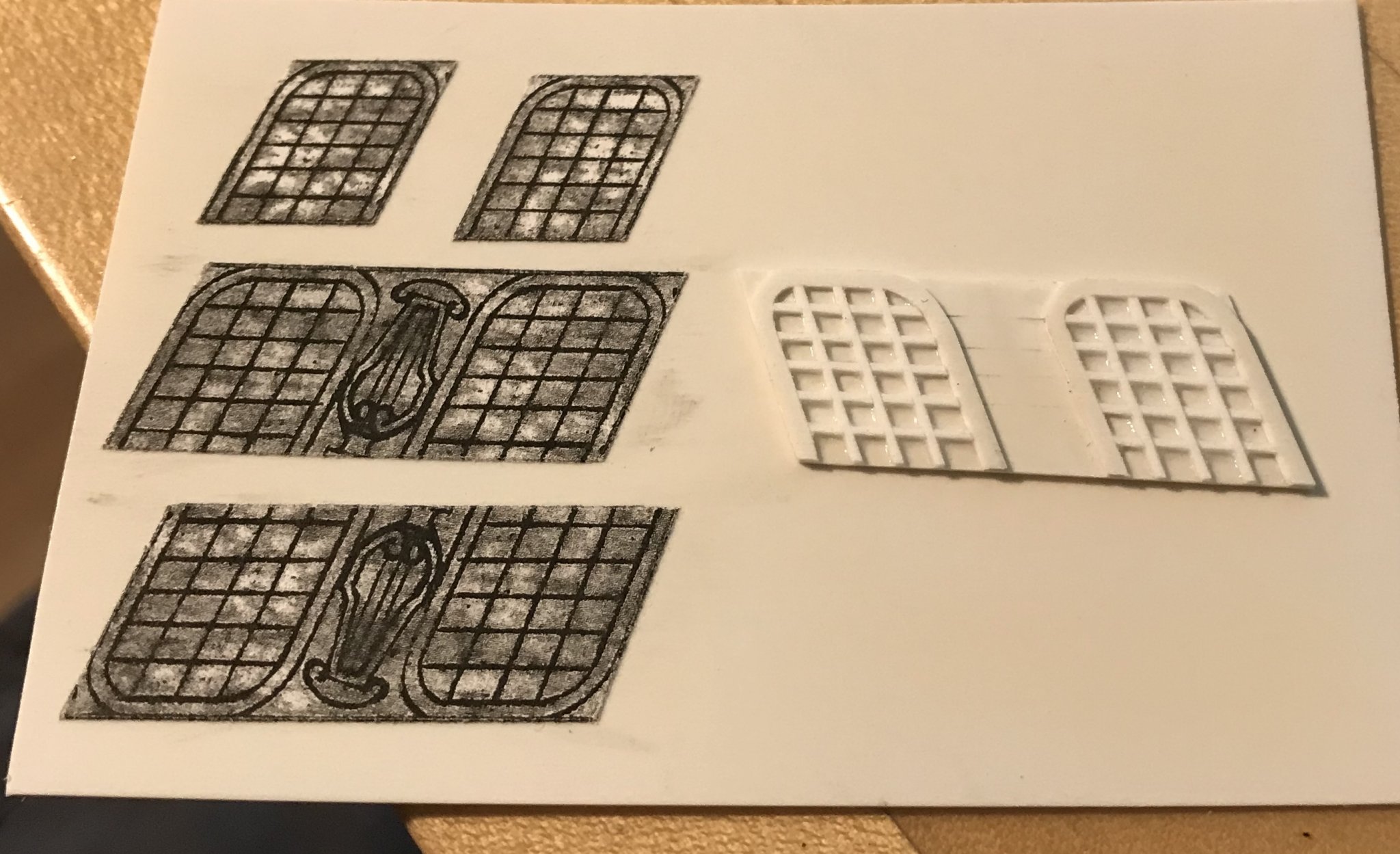
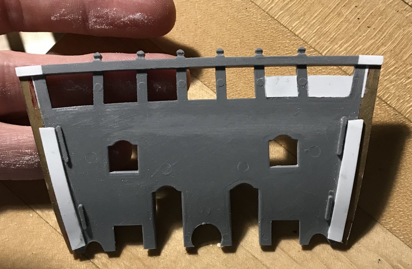
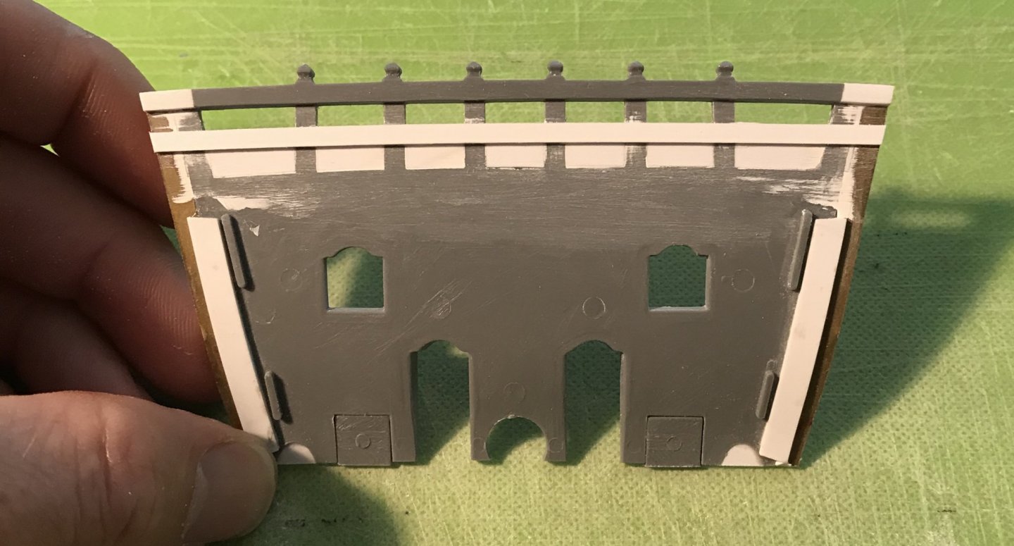
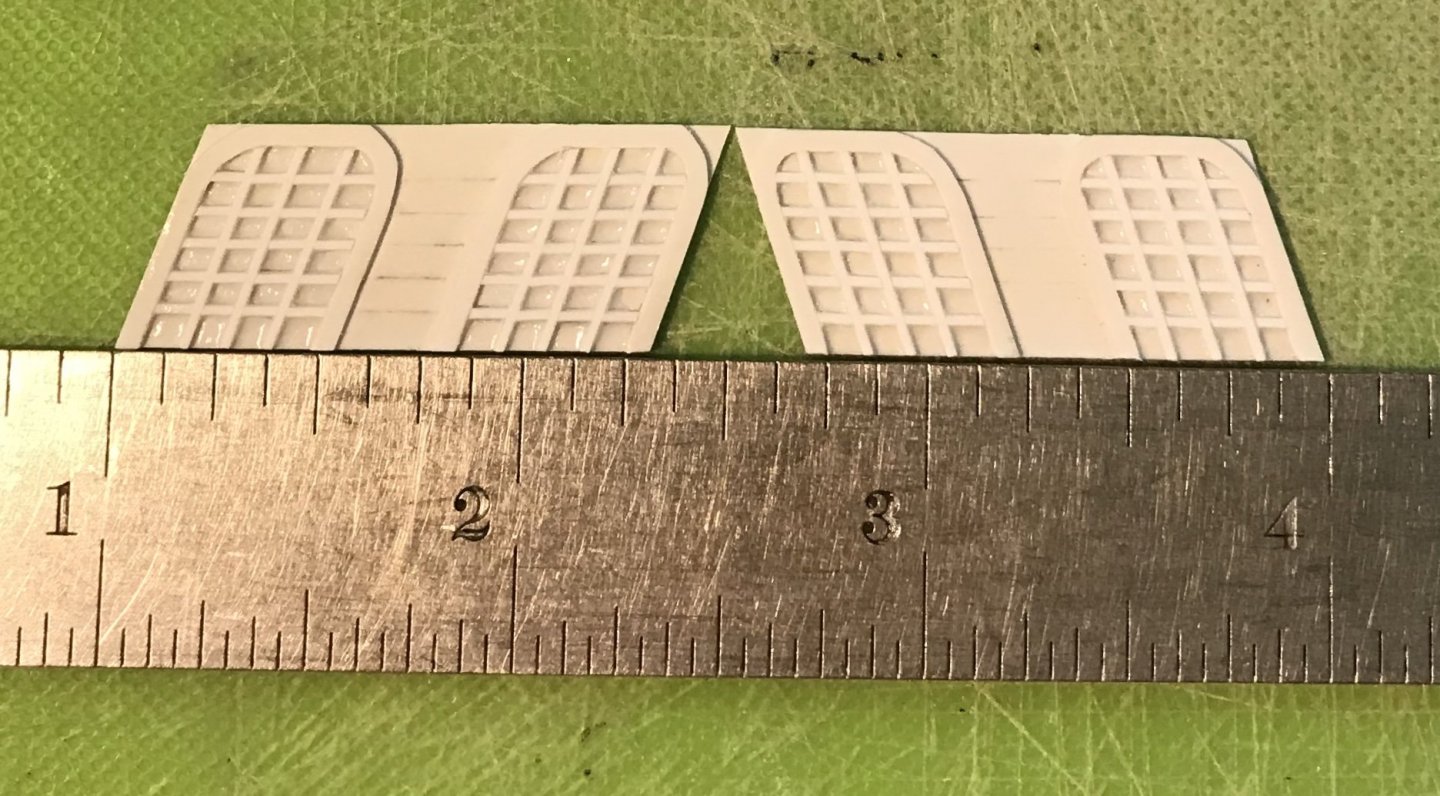
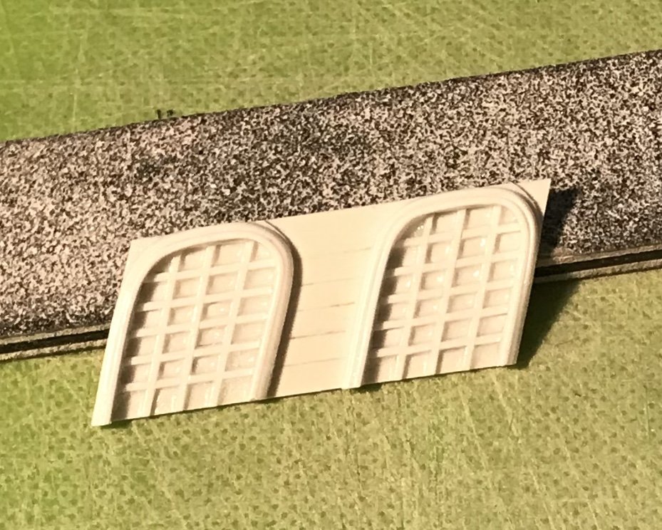
Thank you, Dan! What makes it all the more gratifying is how easy it is to do. Well, this has been a banner week in my mobile shipyard. I’ve made up the false amortisement windows, and I have finished modifying and prepping to paint the beakhead bulkhead. What’s missing is the lyre carving between the windows. I’ll re-draw that this weekend, and get busy making those next week. Now, these windows would be fine, as is, but they’re a little two-dimensional, IMO. Adding just a little bit of moulding gives the windows a better sense of dimension: I will likely just paint them flat black with either white or yellow ocher mullions. I haven’t yet decided. The Beakhead Bulkhead: After grafting-on side extension pieces to make up the extra width of the hull, I decided to close what I find to be the exaggerated open timberhead space on the bulkhead. I will cut-in the cathead timbers, at deck level, when it comes time to install them. Once painted, this paneled effect will disappear. I added another band of moulding to delineate the space: I decided to close the lower chase ports, as they won’t be armed, anyway. I also filled the concavities that would ordinarily accept the lower footing of the roundhouses; these were no longer necessary, as the bulkhead has been set back, by its thickness, so that the ship sides overlap it, as would be the case in actual practice. As a side note - I have found that I really like the Tamiya white putty; it’s much finer than the squadron white, easier to apply and more durable. I, then, scraped away the raised grain; re-engraved the plank seams so that they extended all the way to the ship sides; sanded for texture with 50 grit paper, and drilled for the nailing. To finish up my modifications, I decided to add a field of fleurs, as was often done at this time. I also decided to make use of my foliate diamond ornaments for the band I created when filling-in the timberheads. Next, I’ll prime, paint and install the bulkhead. As always - thank you for the likes and looking in!


- 2,699 replies
-
- 11
-
-
- heller
- soleil royal
- (and 9 more)
-
I’m not sure what scale your Sovereign is, but assuming it is the same as Katherine - this is a fascinating evolution in warship design. Your work and progress are remarkable. I really like the blocks you are using and will have to look into those, myself.
- 1,035 replies
-
- 4
-
-
- royal katherine
- ship of the line
- (and 1 more)
-
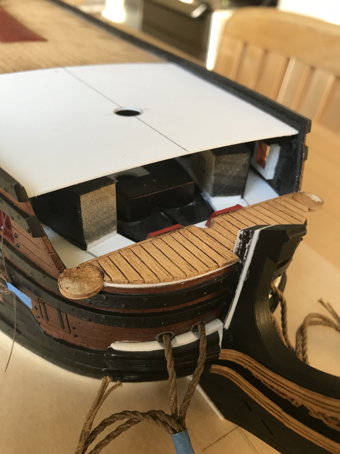
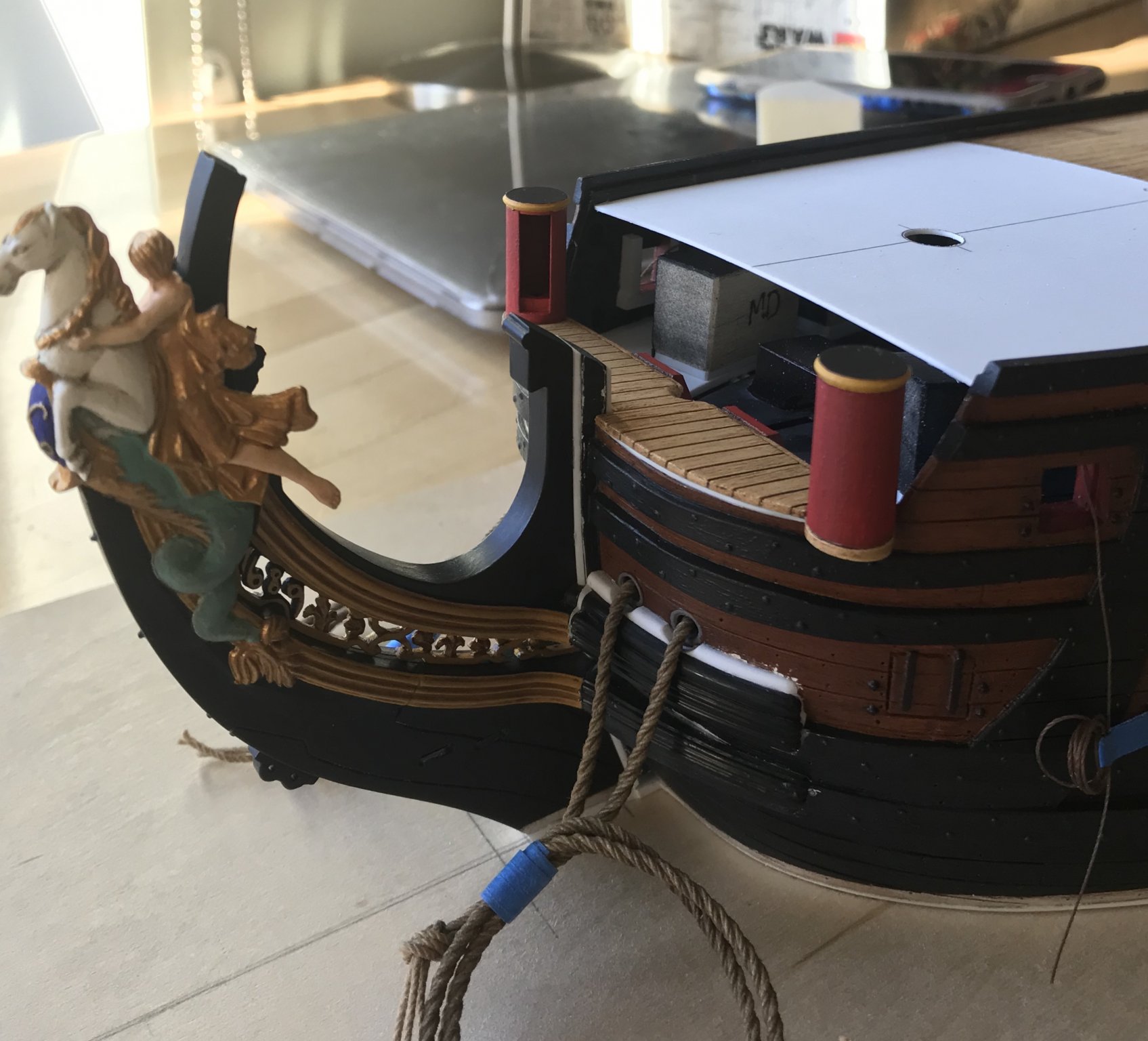
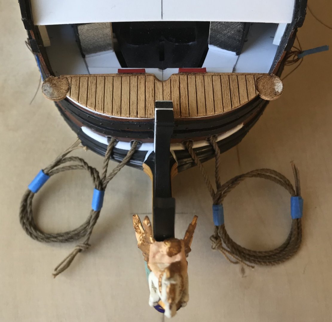
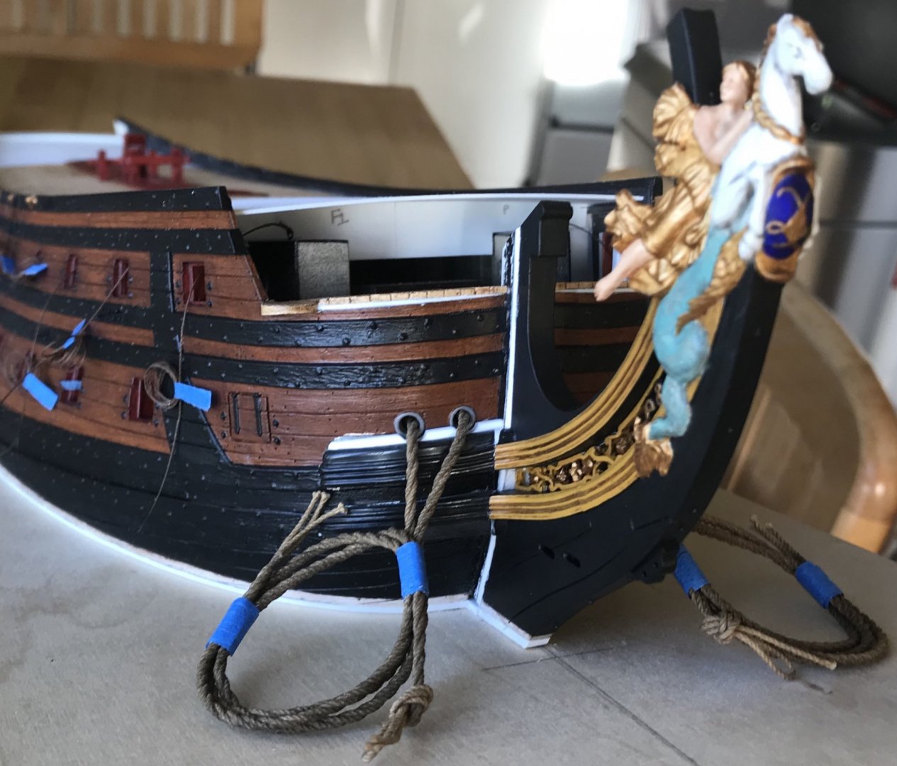
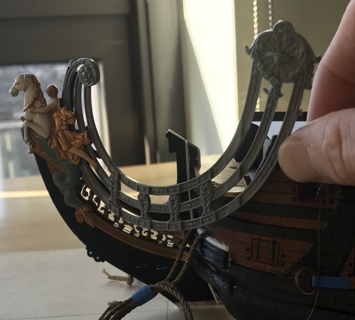
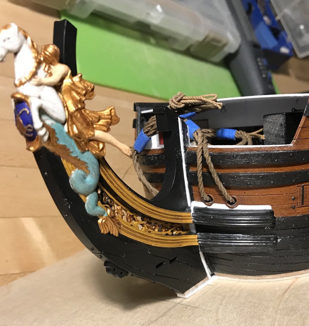
I have heard that sentiment here and elsewhere, and it is my guiding ethos on this build. My objective, always, is to maintain a standard that will allow the viewer to get up really close and scrutinize the work. It isn’t that they won’t find flaws, errors or omissions, but they definitely won’t find any distracting sloppiness. So, the knee extensions are glued-in, and I think the run of their sweep is fair and consistent. I like the look of the raised bolsters around the hawse holes. Given how fragile the artists’ acrylic, raw sienna was when I applied it - I was surprised at how difficult it was to scrape away from the glue areas, a year later. Granted, there was a clear topcoat applied, but it took real effort to scrape the yellow, once you were past the topcoat. There’s a little bit of putty work that still needs to happen, here, and then I’ll prime, paint and repair finishes in the bow area. The beakhead deck is secure, now. You can see the styrene fill, along the leading edge: Filling that gap facilitated a natural camber which should be present, anyway. Ultimately, I have decided that I will maintain the roundhouses. While I agree with Chapman that they probably are not correct, the wrapping hull modification was complicated by the fact that this sweeping wrap extends up into the upper bulwarks. Builders of this kit know that the upper bulwarks are separate pieces that I am nowhere near ready to install. So, I think I will just avoid all of that, on this build, and look to install additional simple seats of ease. Here are the roundhouses painted, but not installed: I have not yet applied the walnut ink wash. This red color, though, will be what I apply to the beakhead bulkhead, along the run of the main deck ports, selectively throughout the lower quarter galleries, and throughout the stern facade. It is also an artist acrylic, proprietary mix for BLICK. I’ve thinned it considerably with water, and the color lays down beautifully in thin coats. I have found that the artists’ acrylics are hit or miss. Fortunately, my blues are going to work! I also picked up a bottle of the Tamiya X20 thinner for acrylics, and this helped with the application of my yellow ocher, so that was a great help. I’m finishing up my starboard amortisement dolphins, and I was amazed to realize that they are about 1/32” taller than the port side: Here, I have the P&S forward carvings back to back: I double-checked the 90% reduction photo copies and there is no distortion from one side to the other. They match up perfectly. I can adjust this, so that both sides match, but it remains a mystery. I have figured out what the process will be for making the false amortisement windows that go between these dolphin carvings. Those will be my next small-work project, and I think they should be relatively straight-forward. Here is the stock port headrail, as it currently aligns: Unfortunately, I will not be able to use these; the headrails need to lap the hull by about another 1/4”, and there is no feasible way to stretch or modify these so that they look good and right. Patterning new ones will enable me to correct the problem of the forward scroll rising up, alongside the sprit-mast, thus spoiling the line fairleads. I will also be able to space the headrail vertical timbers (decorated with lyres in Berain’s drawing) so that they align with the headrail supporting timbers. This way, I can space those supporting timbers, along the trailboard, in a way that makes sense. Ultimately, I believe that I can graft the forward scroll and rear escutcheon onto the new headrails, thus saving an enormous amount of time. If I can achieve all of that, I will have done justice to the bow. Before I do my paint touch-ups, I’ll get busy extending the beakhead bulkhead and getting that in place. Thank you all for looking in. Enjoy this last week of the summer, as best you can!


- 2,699 replies
-
- 18
-
-
- heller
- soleil royal
- (and 9 more)
-
Thank you so much, Mark! I’ve been thinking quite a lot, lately, about the relative ease of constructing the model straight out of the box; with the number of hours that I have invested in these head structures, one would reasonably expect much more to show for it. In fact, it is absurd to me, at times, to consider that this is the single project that I have ever undertaken, that has consumed the greatest amount of focused concentration and effort. A plastic model. But there is no rhyme or reason to what the heart desires, and my heart wishes to transform this really pretty good plastic kit into something fairly spectacular. Despite its relatively ephemeral nature, the project has given back to me everything that I have put into it, so far. But, I won’t be doing this sort of project ever again 😉
- 2,699 replies
-
- 3
-
-
- heller
- soleil royal
- (and 9 more)
-
These upper knee extensions have been a real challenge to fit, so far. A big part of the challenge is that I raised the upper knee a solid 1/32”, in order to buy a little extra space for the trailboard. That modification, though, did result in the need to add and shim with new plastic. One upgrade that I wanted to attempt was to raise the cheeks, surrounding the hawse holes, which I think I reasonably succeeded at. In this reverse-engineering environment, it isn’t perfect, but I think it is passably better than stock. Be well, and thank you for looking in!
- 2,699 replies
-
- 11
-
-
- heller
- soleil royal
- (and 9 more)
-
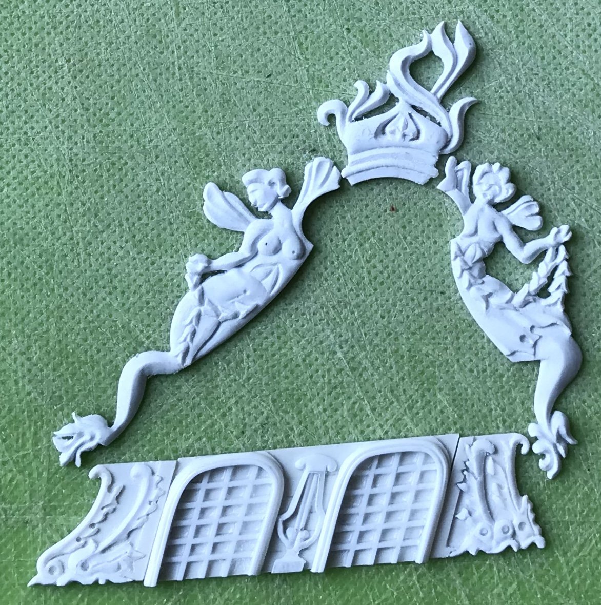
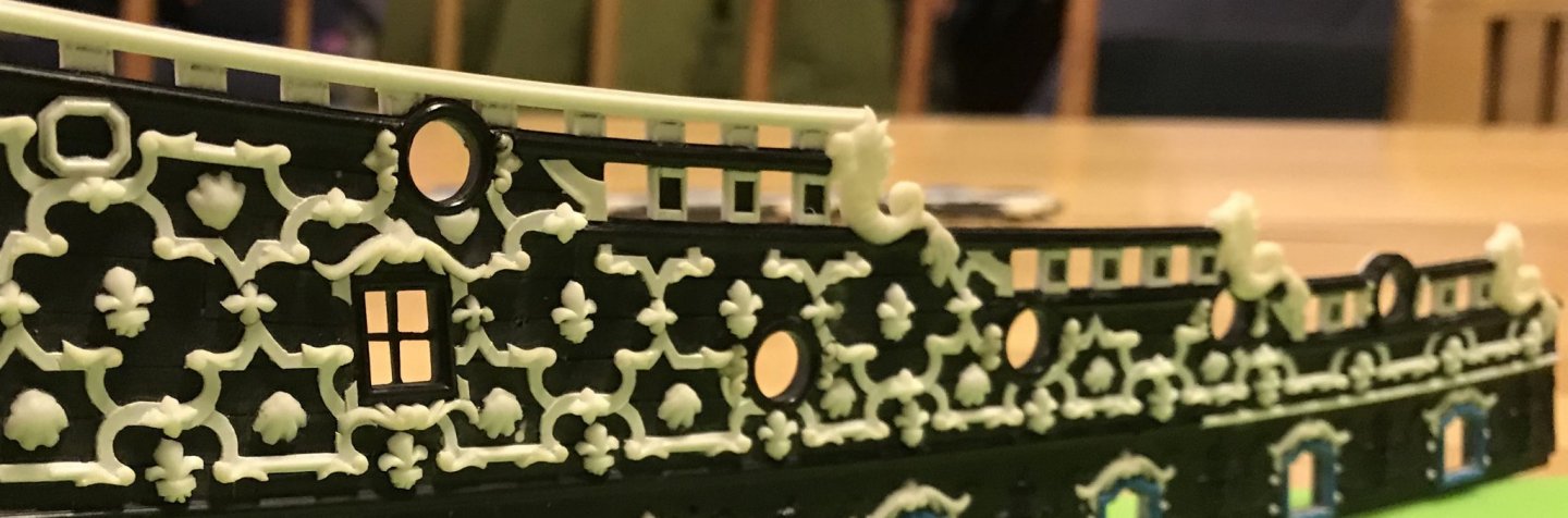
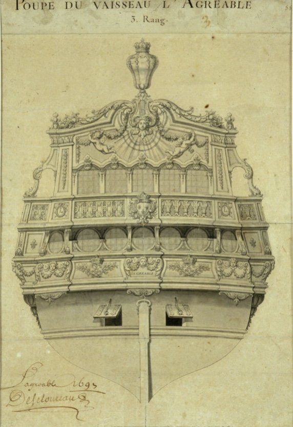
Here’s a small, but I think interesting realization I had over the weekend. Berain’s new ornamental scheme for L’Agreable also incorporates small winged fairies: This is interesting to me because even at this later date, winged fairies are still part of Berain’s design vocabulary. Skeptics of the authenticity of the mermaid pixies, on the amortisement, tend to view them as something that may have been present much earlier than 1689 - perhaps as part of the original ornamental scheme. I tend to think that their presence, here on L’Agreable, at the hand of Berain, re-enforces 1689 as the more likely contextual time frame for my quarter gallery design. These figures are cherubs, and not specifically female, but note the presence of swaged garlands, below. This is all consistent with the ornamental language of Soleil Royal.
- 2,699 replies
-
- 5
-
-
- heller
- soleil royal
- (and 9 more)
-
Every bit of this is just astonishing. I don’t often comment, here, but I have been watching with great interest. Your care and precision of execution are enviable, indeed!
-
I hear what you’re saying Chapman, although if I were serving on a ship like this, I wouldn’t mind having a little extra shelter around me while I do my business.
- 2,699 replies
-
- 1
-
-
- heller
- soleil royal
- (and 9 more)
-
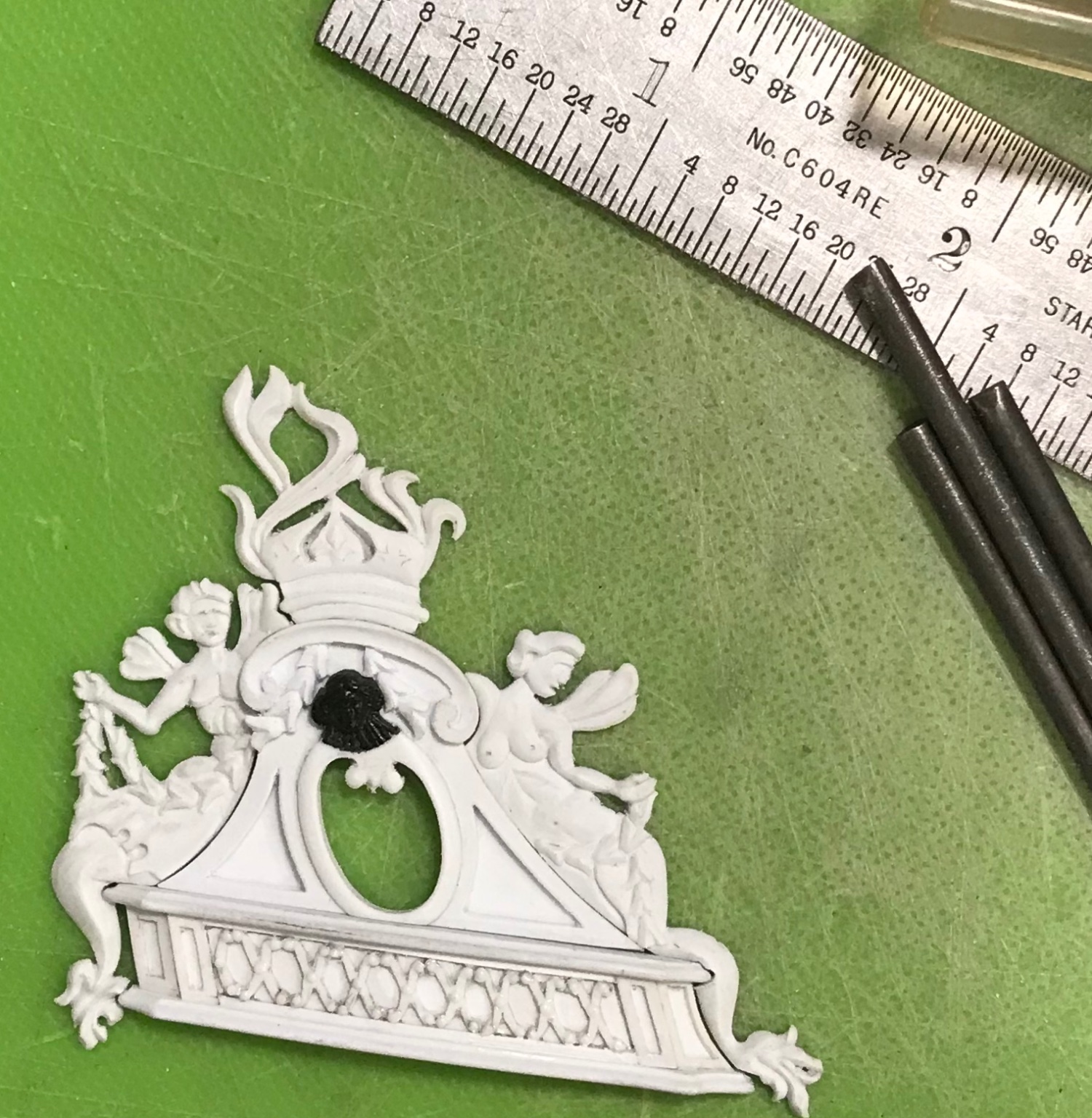
These are difficult to photograph, but I am very happy with the modeling and the overall impression of these: Now that I have worked through the problems, the starboard pair should come out even better. To finish these off, I’ll insert domed bits of styrene rod into the eye sockets. I really appreciate all of the likes and kind comments!
- 2,699 replies
-
- 10
-
-
- heller
- soleil royal
- (and 9 more)