
Beckmann
-
Posts
400 -
Joined
-
Last visited
Content Type
Profiles
Forums
Gallery
Events
Posts posted by Beckmann
-
-
-
-
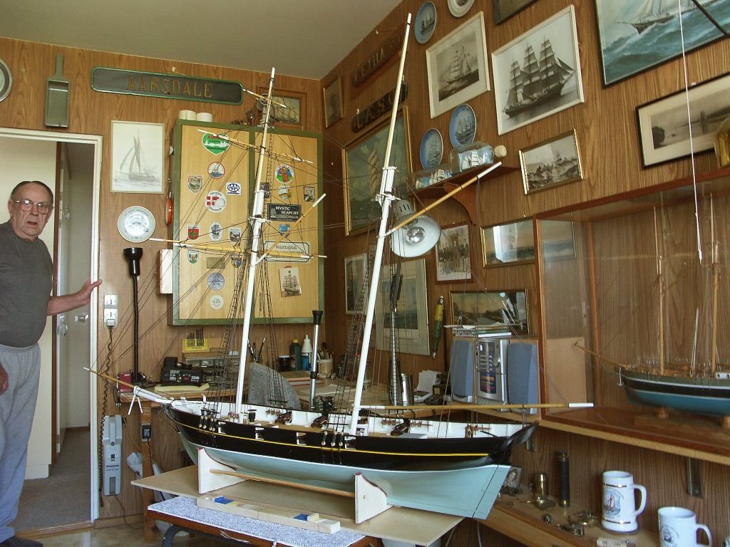
Hi Chris. Very nice. Will they be available as separate Figures as well? I play the Cello myself and would love to have them both sitting in my 1:32 scale captains cabin.
Matthias
- hollowneck, TJM, Ronald-V and 5 others
-
 8
8
-
Hi JJ,
did you develop the carvings yourself, or is there another artist involved?
Matthias
-
Hi Chuck,
I would take one. Great idea!
Matthias
- Jack12477, Canute and thibaultron
-
3
-
-
That looks much better now. Well done!
Matthias
- hollowneck and TJM
-
1
-
 1
1
-
Hi TJM,
Somehow the QG leans backward and the roof leans forward, shouldn't both lean backward?
But beautifully done anyway,
Matthias
- TJM and JacquesCousteau
-
2
-
-
Hi Jack,
that is a nice any helpful jig you created. Well done.
Matthias
- scrubbyj427 and Jack H
-
2
-
Hi Jack, I am looking forward to this. What are your plans? With, or without planking? Frames visible or not?
Matthias
- Jack H and AnobiumPunctatum
-
2
-
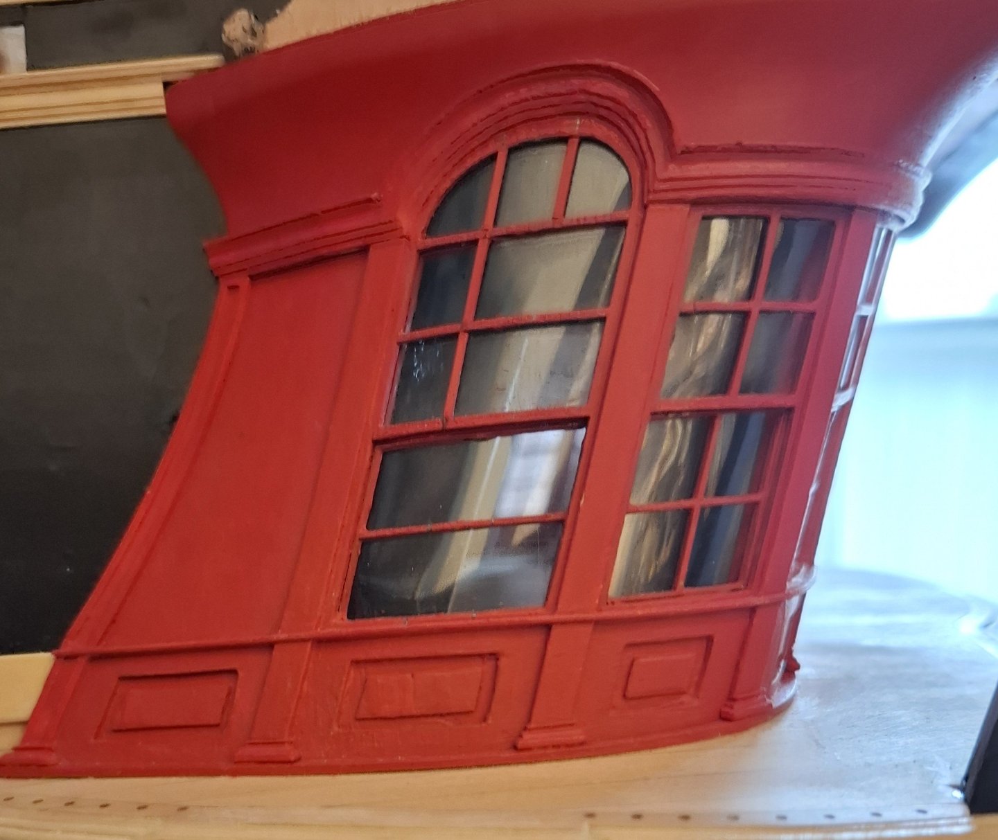
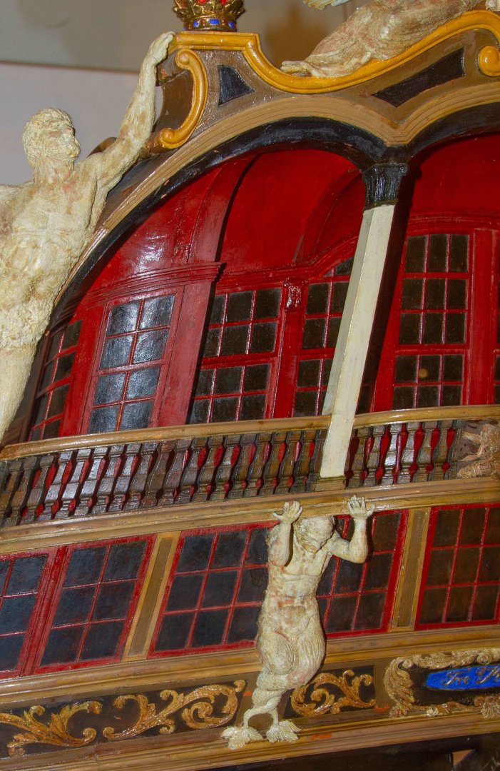
Thank you all for your encouragement and the likes!
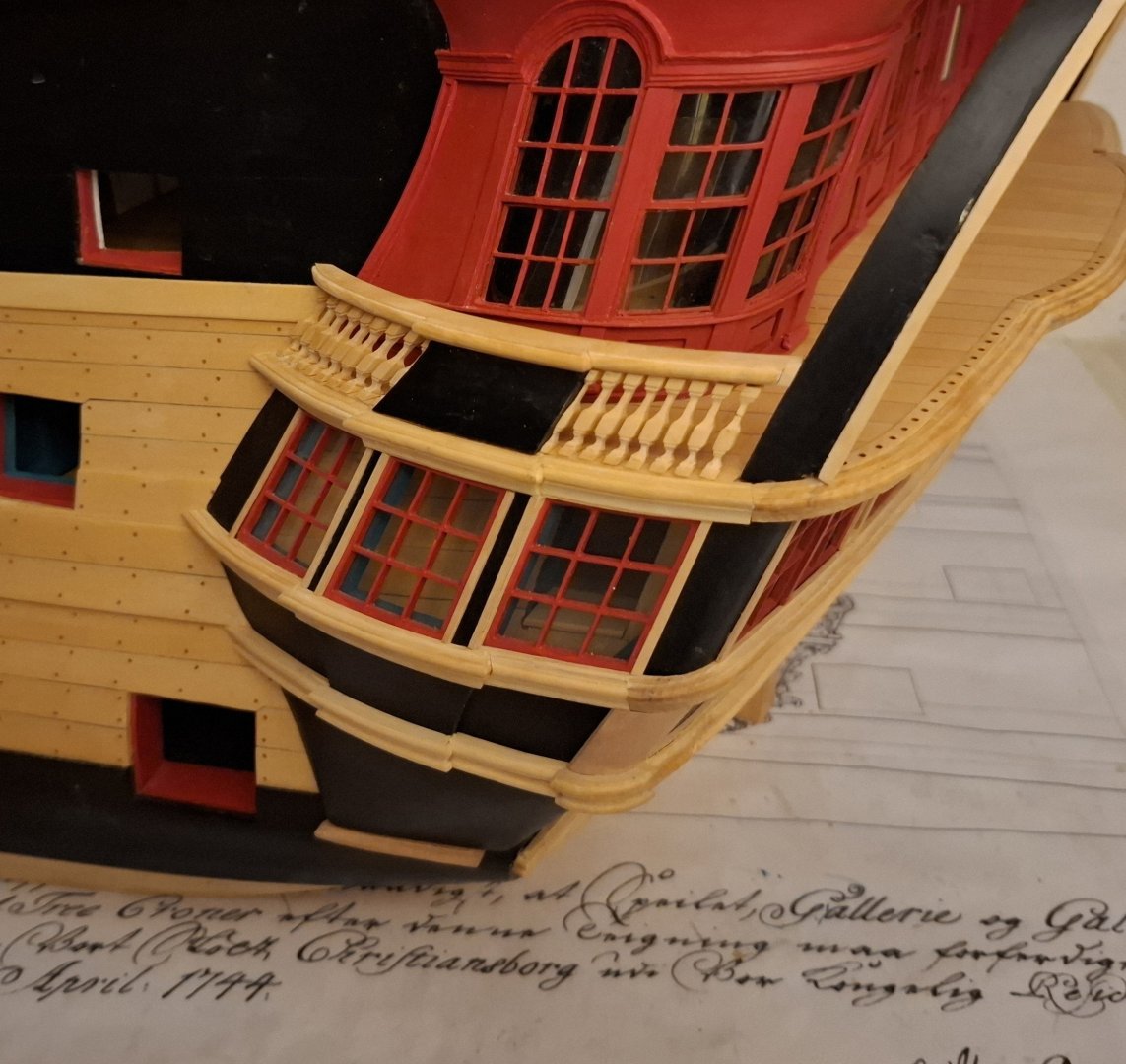
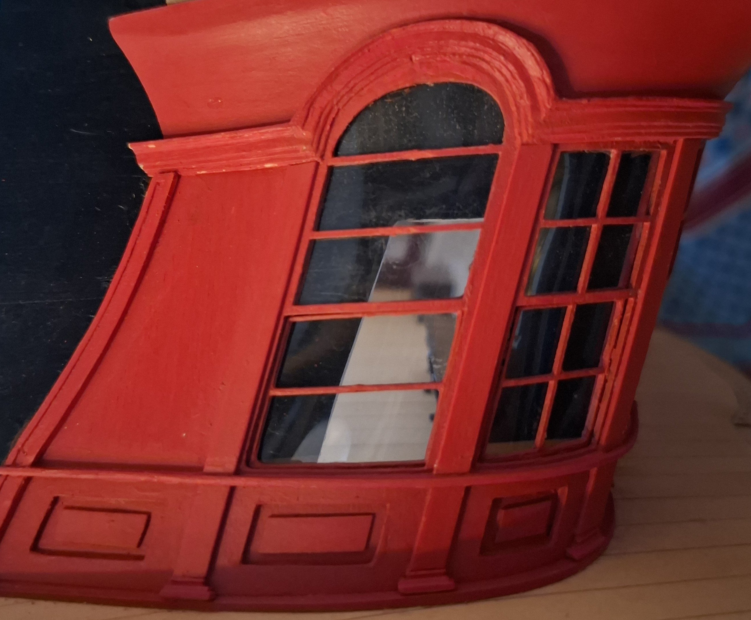
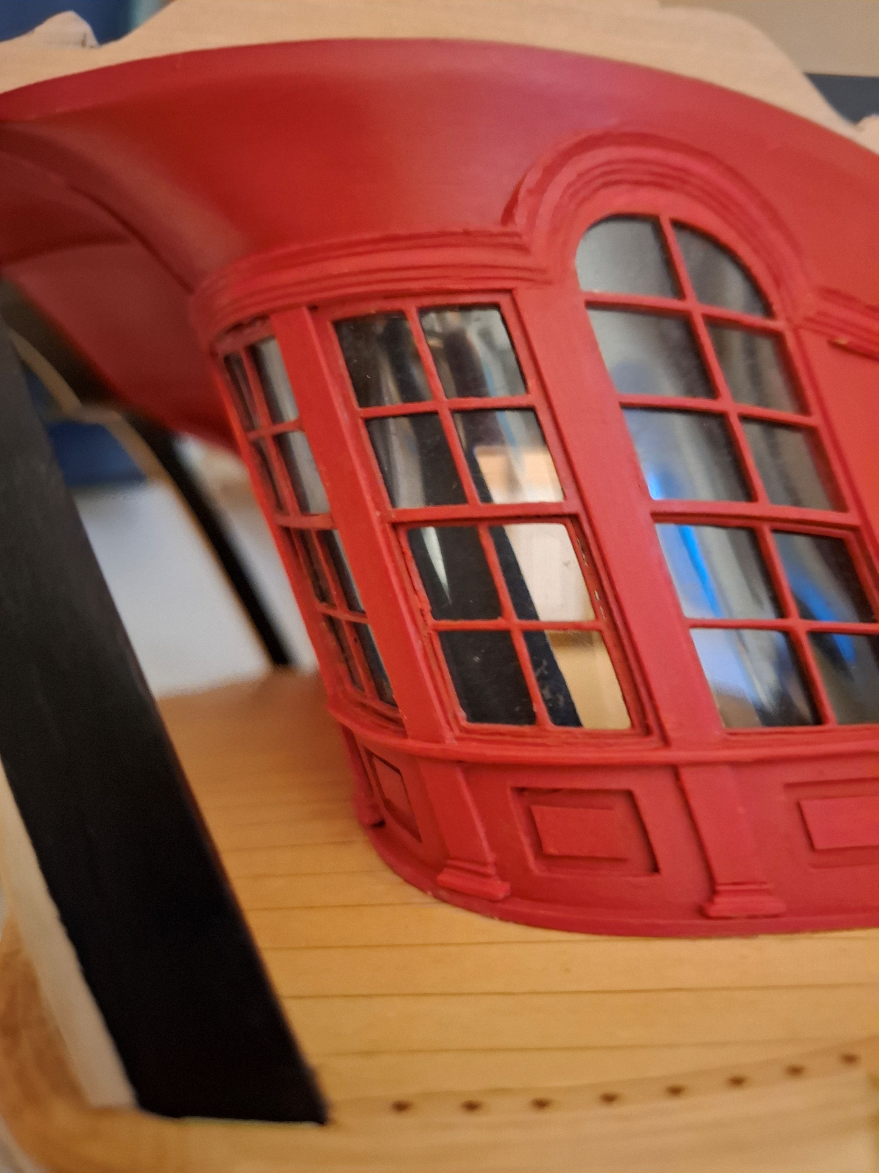
Today, I first need to address an issue, namely my incorrectly constructed window in the upper side gallery.
I had a window here that was actually intended to have double glazing bars, but I inadvertently constructed it with a single central glazing bar, which resulted in horizontal window panes that should otherwise all be vertical. The problem is that the window is glazed and curved under tension. So replacing the entire muntin bar was out of the question. I would never have been able to fit the new window cross neatly into the curve. The only option was to carefully cut out the centre muntin bar and insert new muntin bars. Here is the result: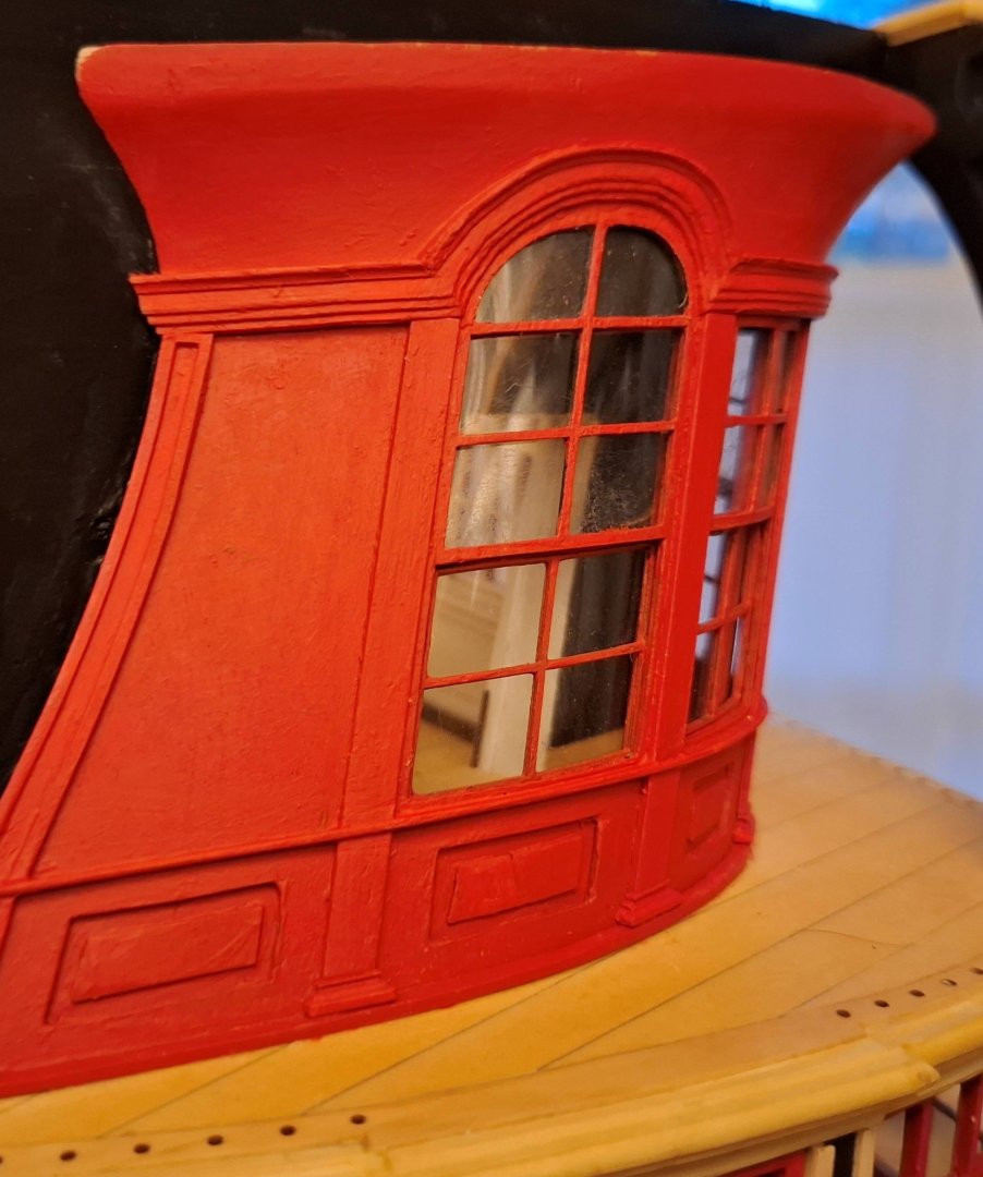

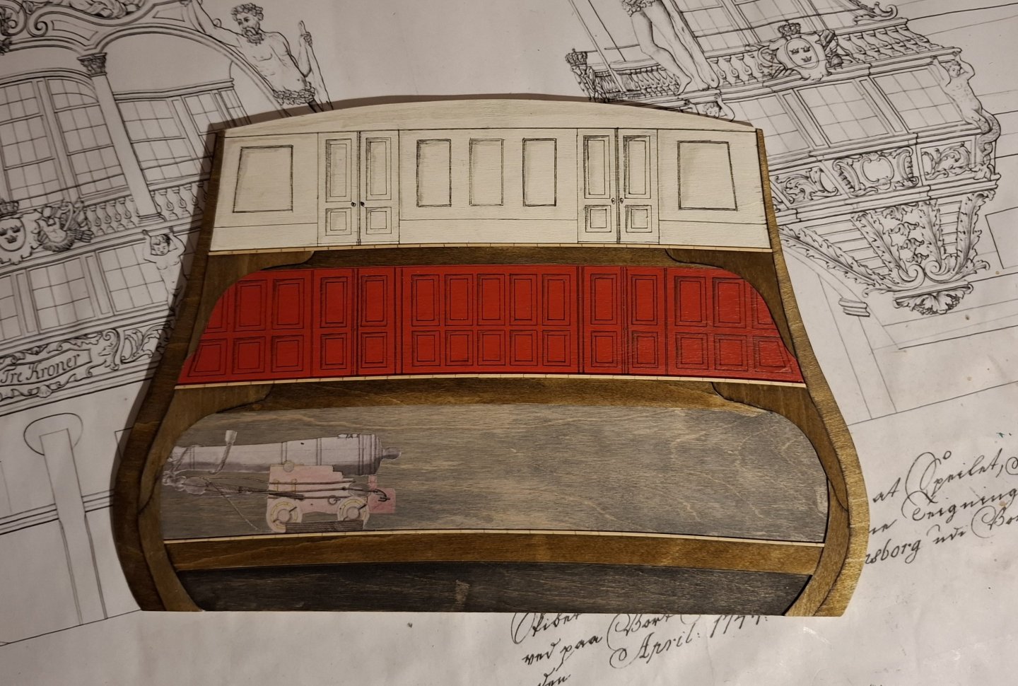
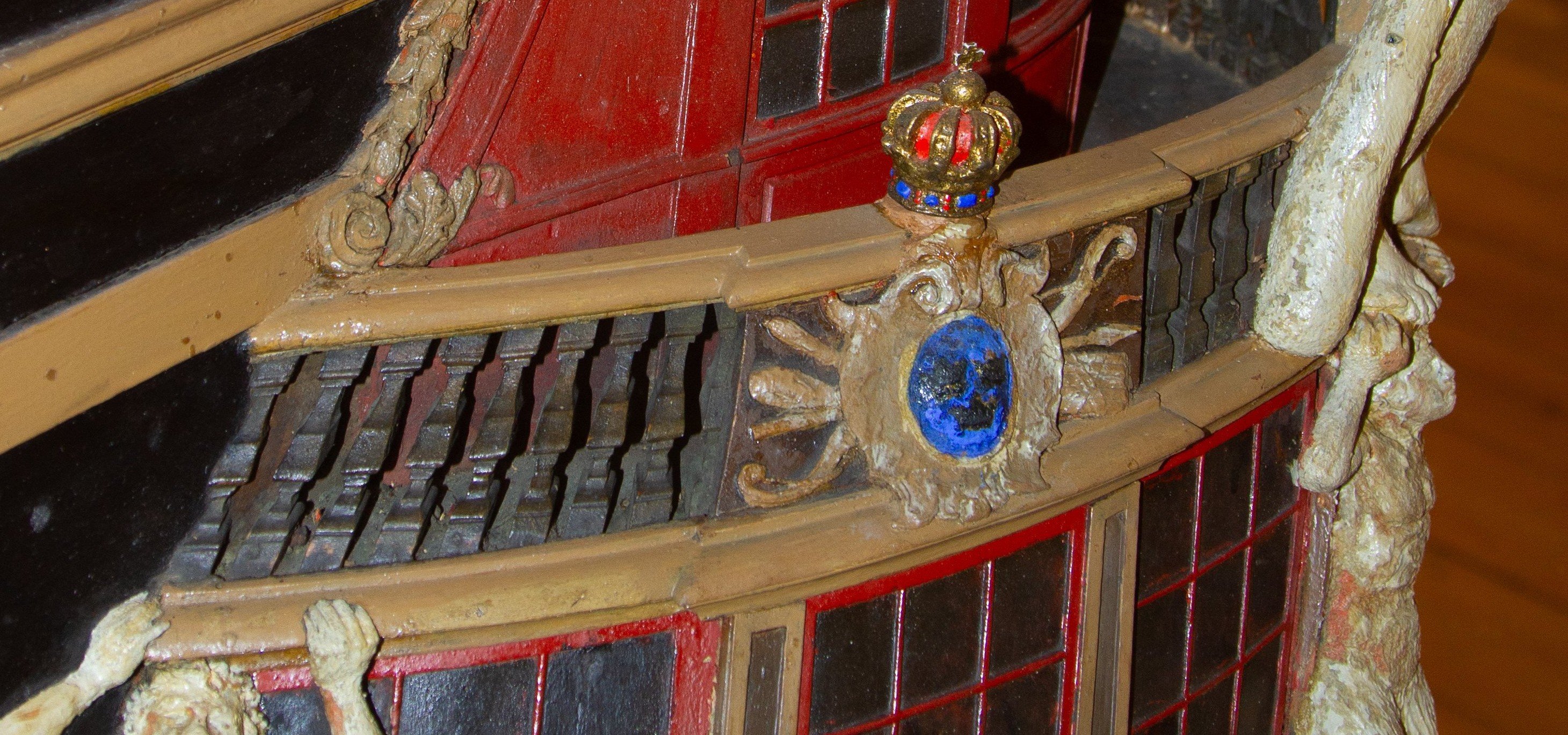
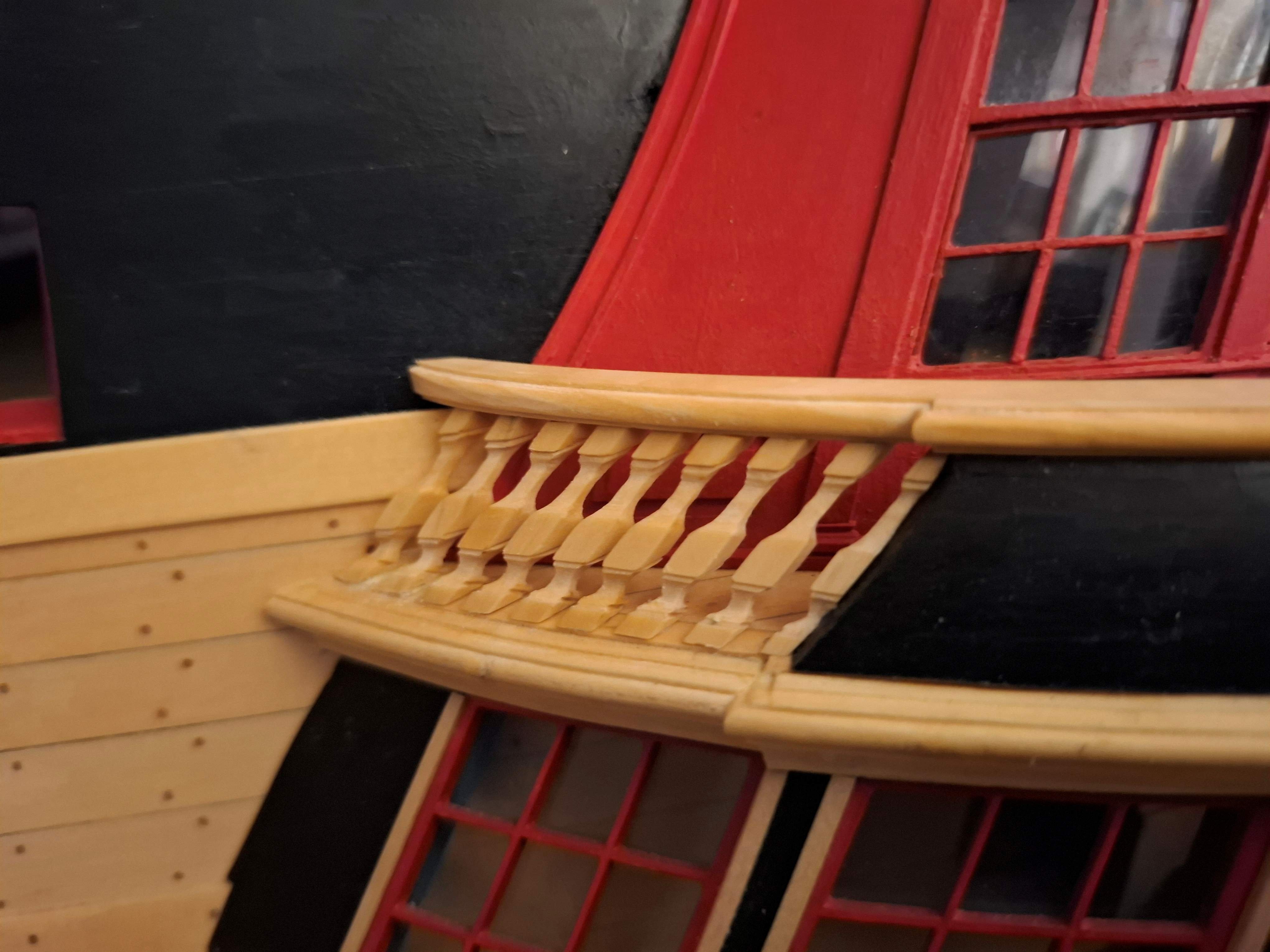
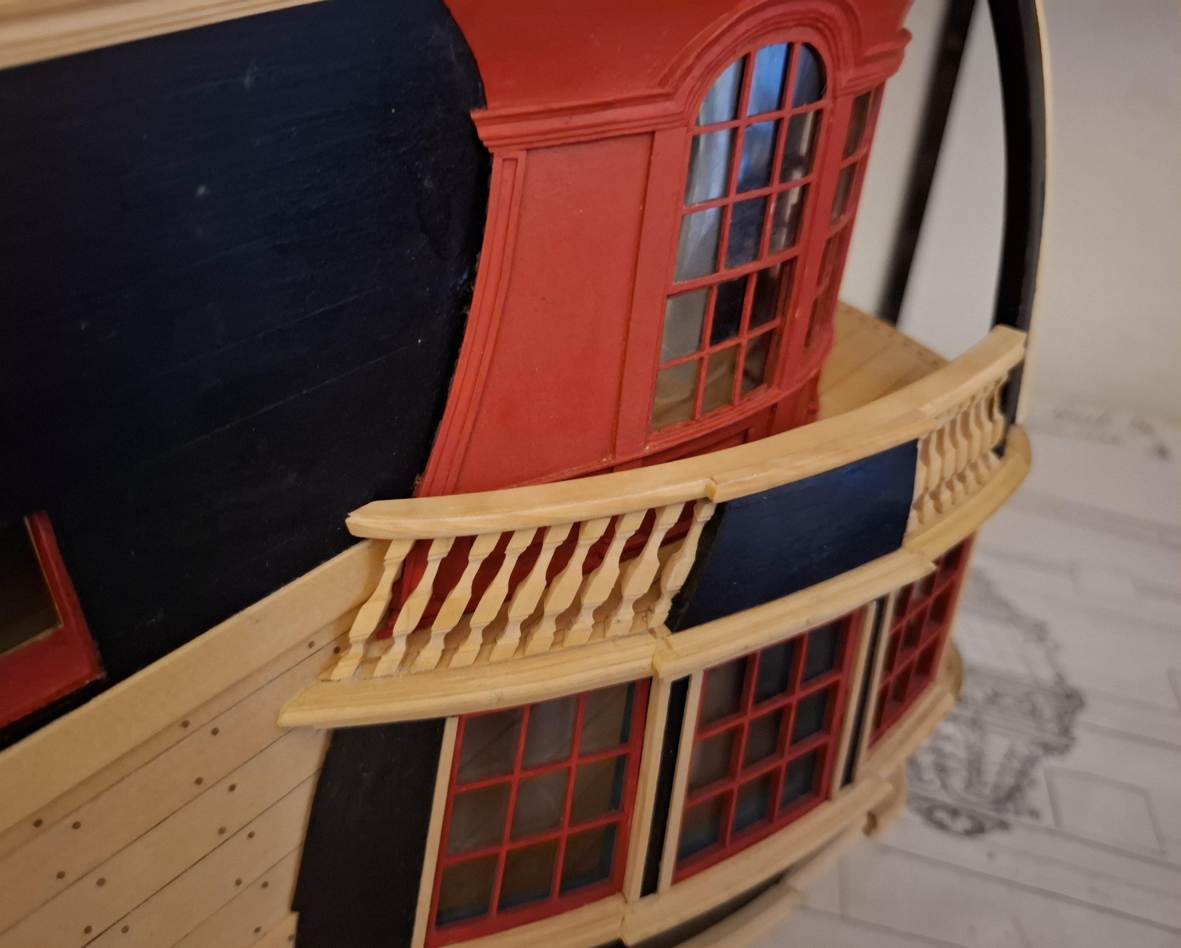
Next, I turned my attention to the gallery railing, a task that I had been puzzling over for a while and which, at least on the starboard side, has not yet been satisfactorily resolved.
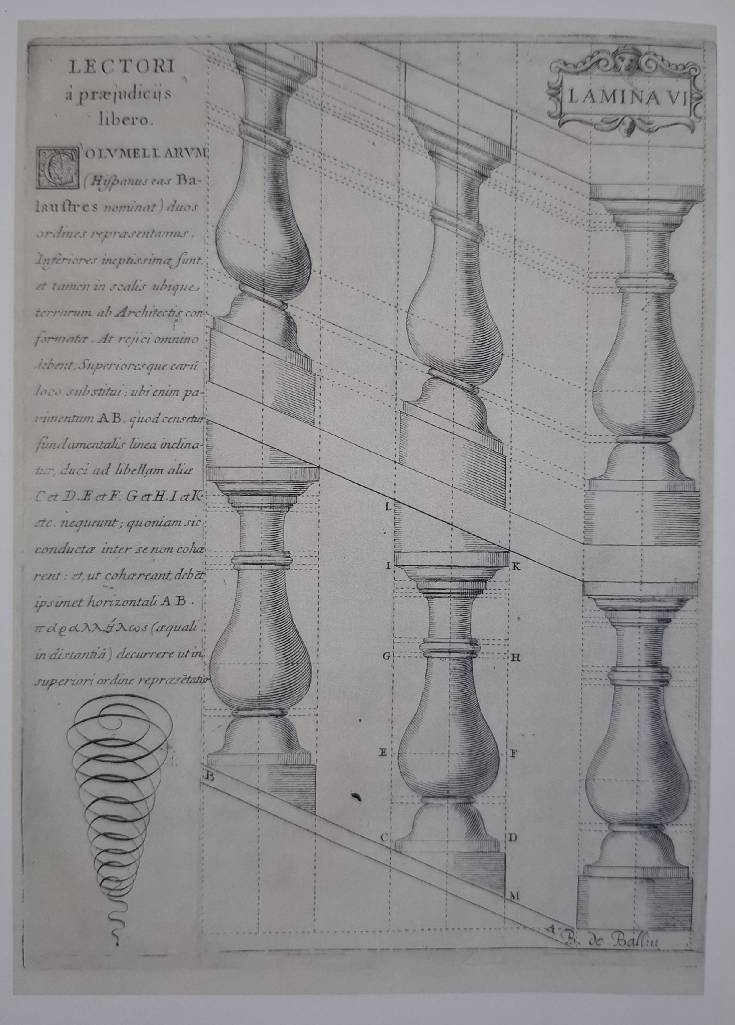
The gallery railing consists of a balustrade, similar to those often found in stone on elaborately designed Baroque balconies or staircases. The individual gallery balusters feature multiple coving, thickening and tapering. To make matters more difficult, they are tilted, in the case of the side gallery backwards and inwards. At the rear, they are later tilted backwards and outwards. One could make things easy and make them all the same and tilt them accordingly. This is sometimes done in architecture for staircases. Then, in the transition to the inclined contact surfaces, wedges are simply placed underneath and above. To illustrate this, here is a drawing from the 17th century: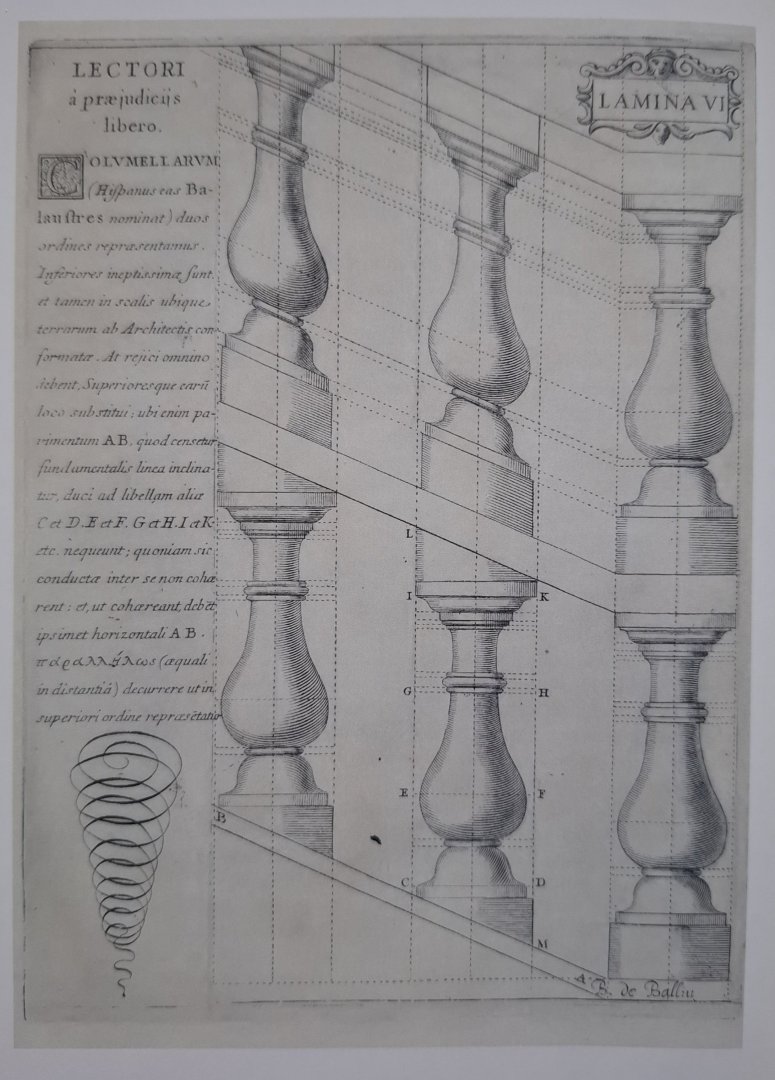
However, since the TRE KRONER model has a tilt here, I have to try that too, of course.

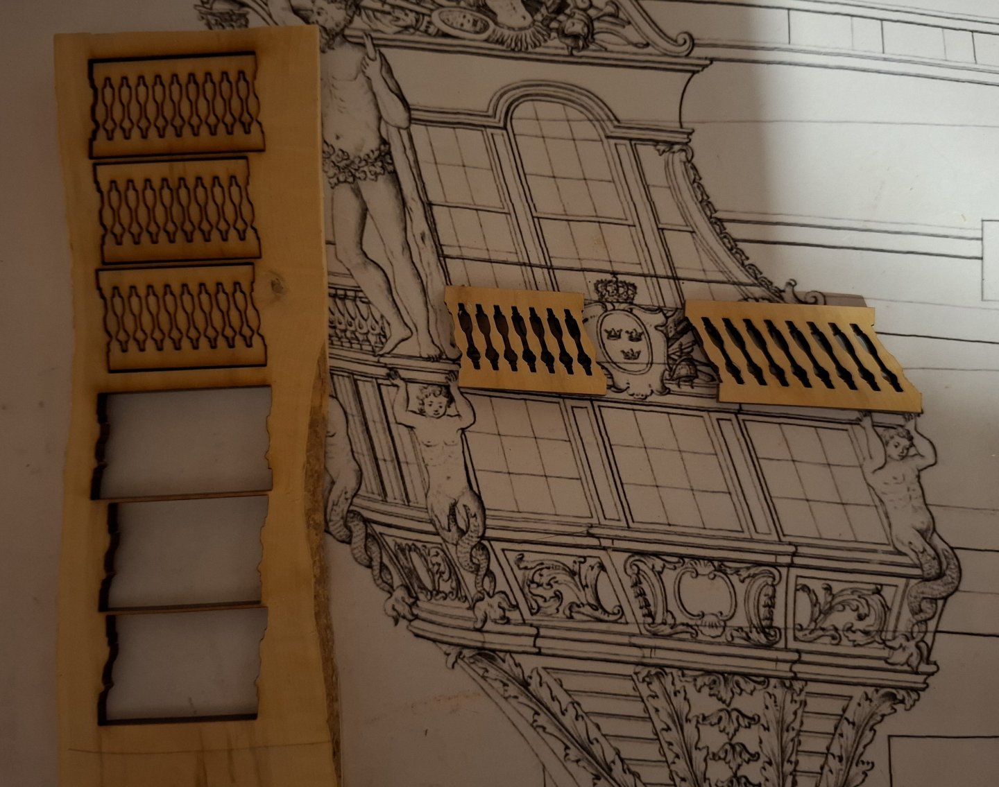
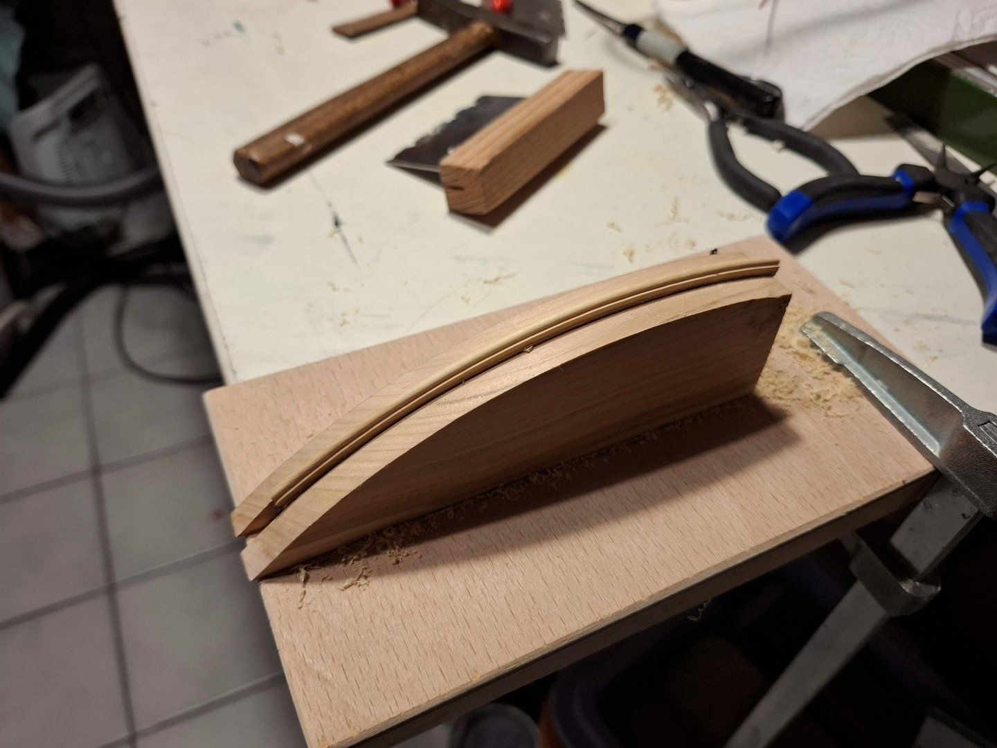
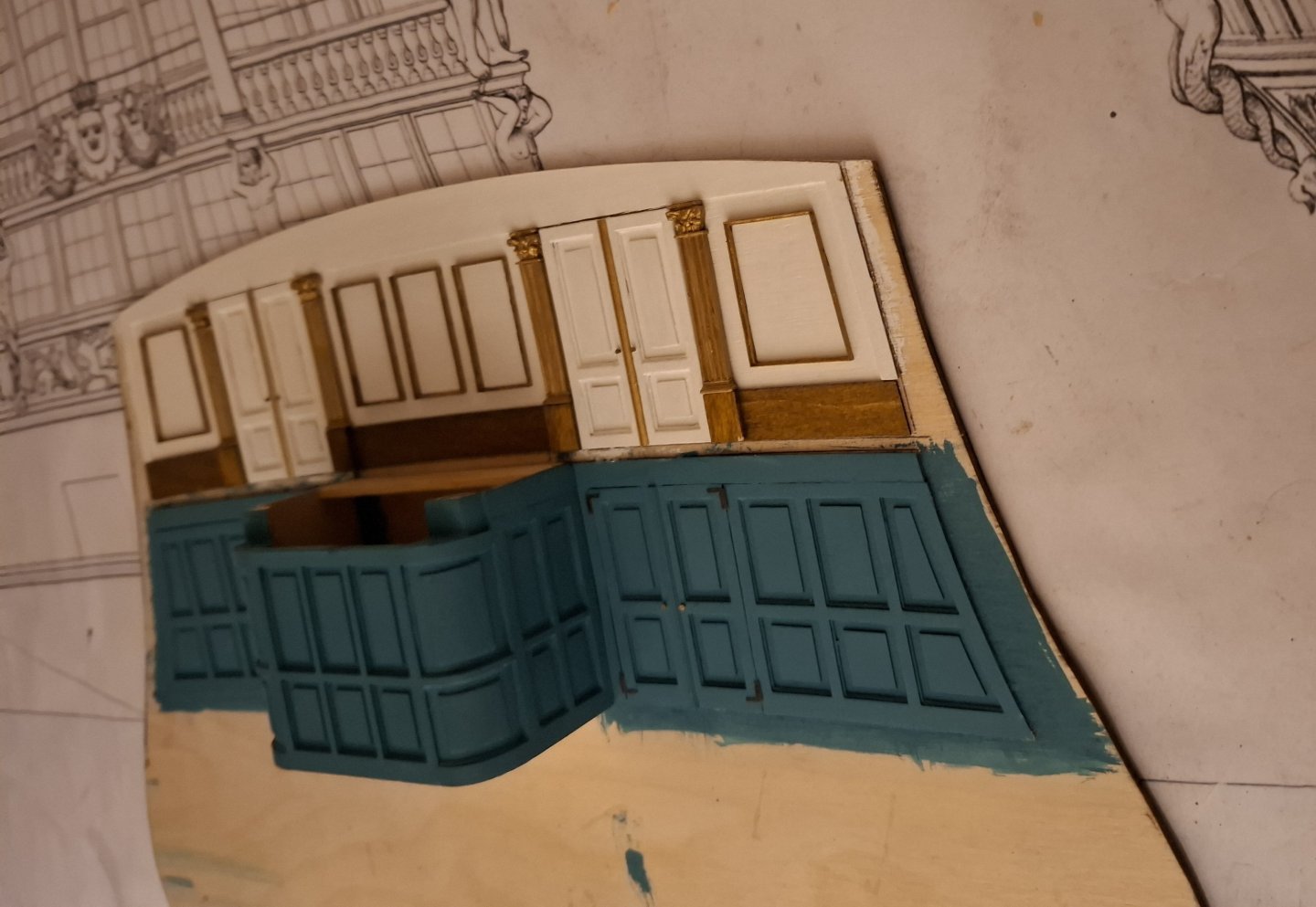
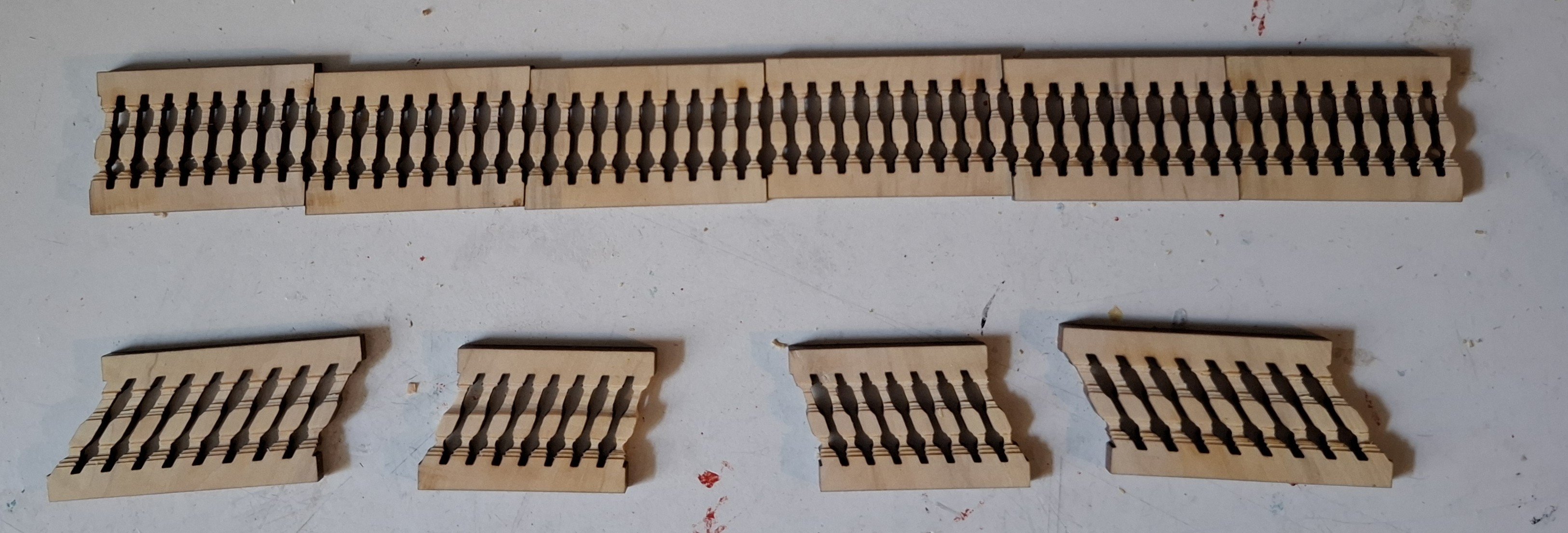
I then drew and cut out the tilt towards the rear.
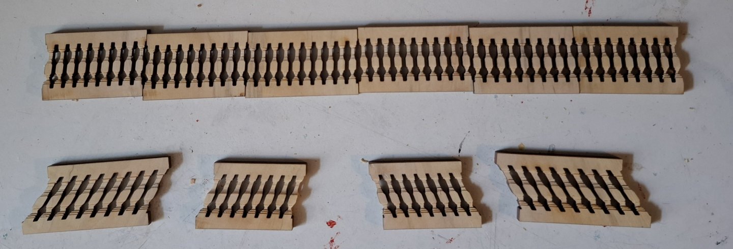
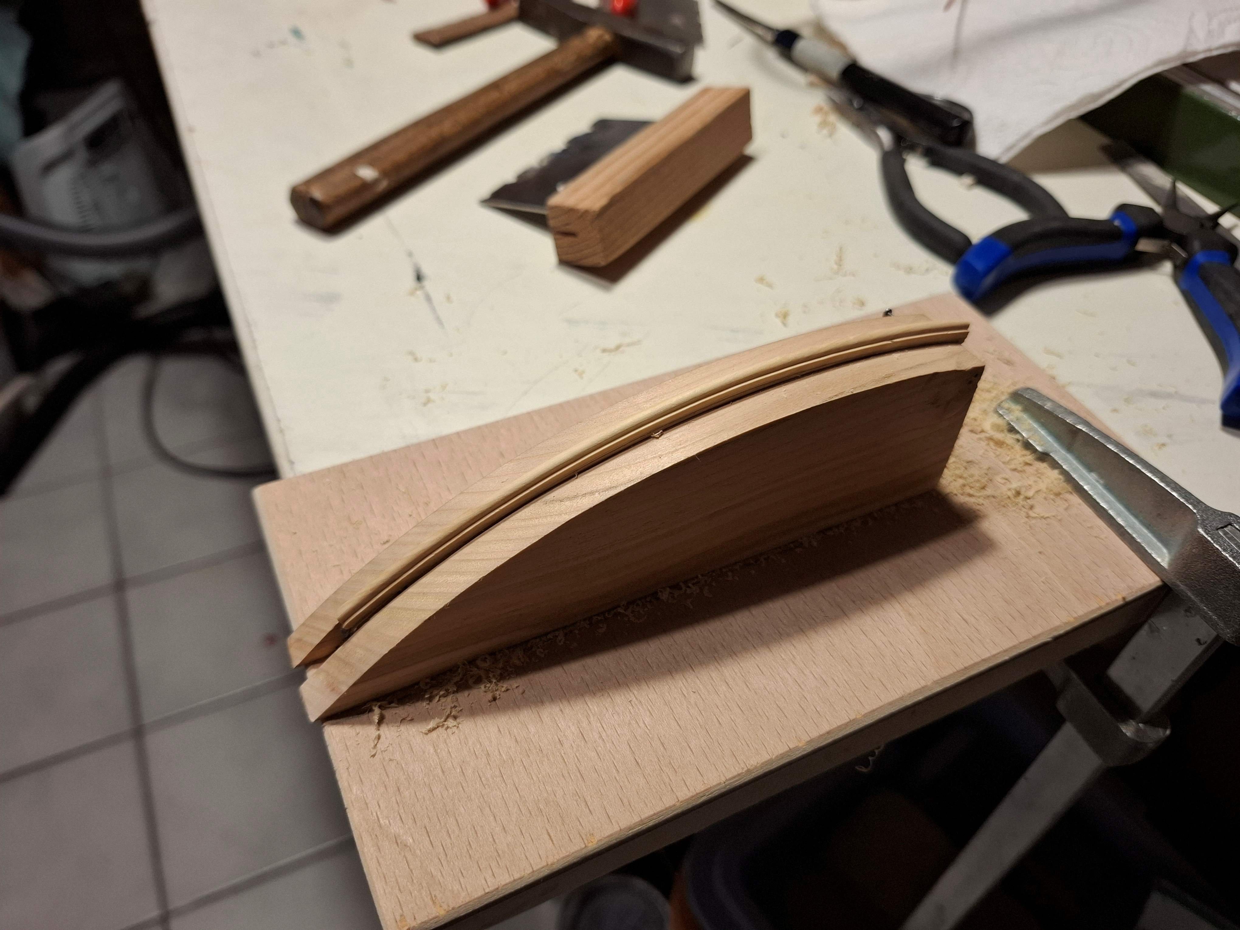
The profile was roughly pre-cut on the circular saw and then finished with a file.
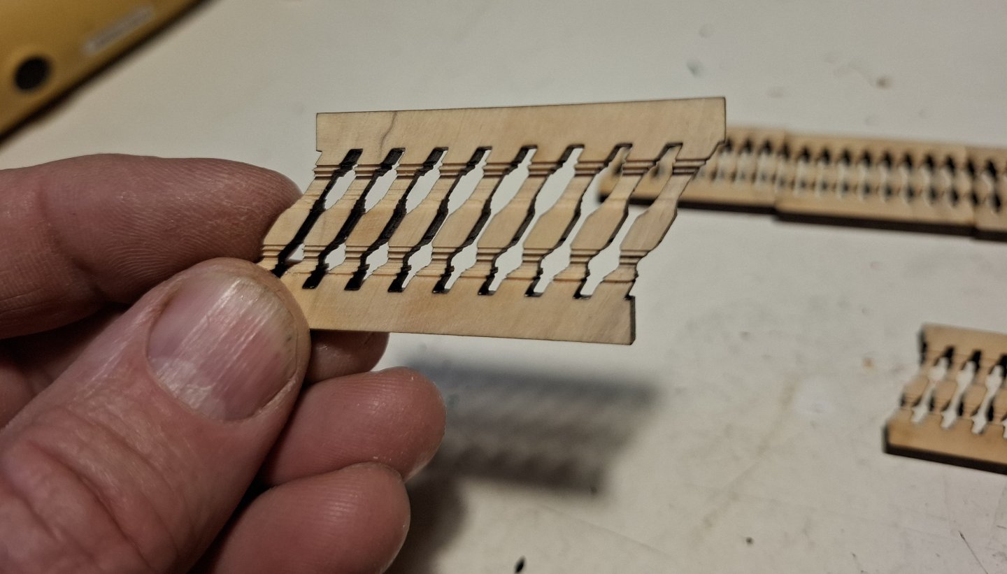
The inward tilt was also worked on as best as possible at the front ends with a file and a carving knife.
The railing rail was drawn on a template.
A hole was drilled and fitted with a small wooden dowel to secure it to the contact surface. Finally, everything was inserted, aligned and glued to the upper railing rail.


Some of the inclines are not quite right. If you build the whole thing two or three times in a row, it will probably get better and better. But I'll leave it like this for now, as it's a lot of work.
Best regards,
Matthias -
This is a lovely project, well done Scrubby. Your aproach to the building is masterly. Of course CAD helps, but one has to solve all the problems in ones own mind before drawing things.
When do you plan to release the project?
Matthias
-
That looks superb, lovely framework.
Matthias
- FrankWouts, CiscoH and scrubbyj427
-
2
-
1
-
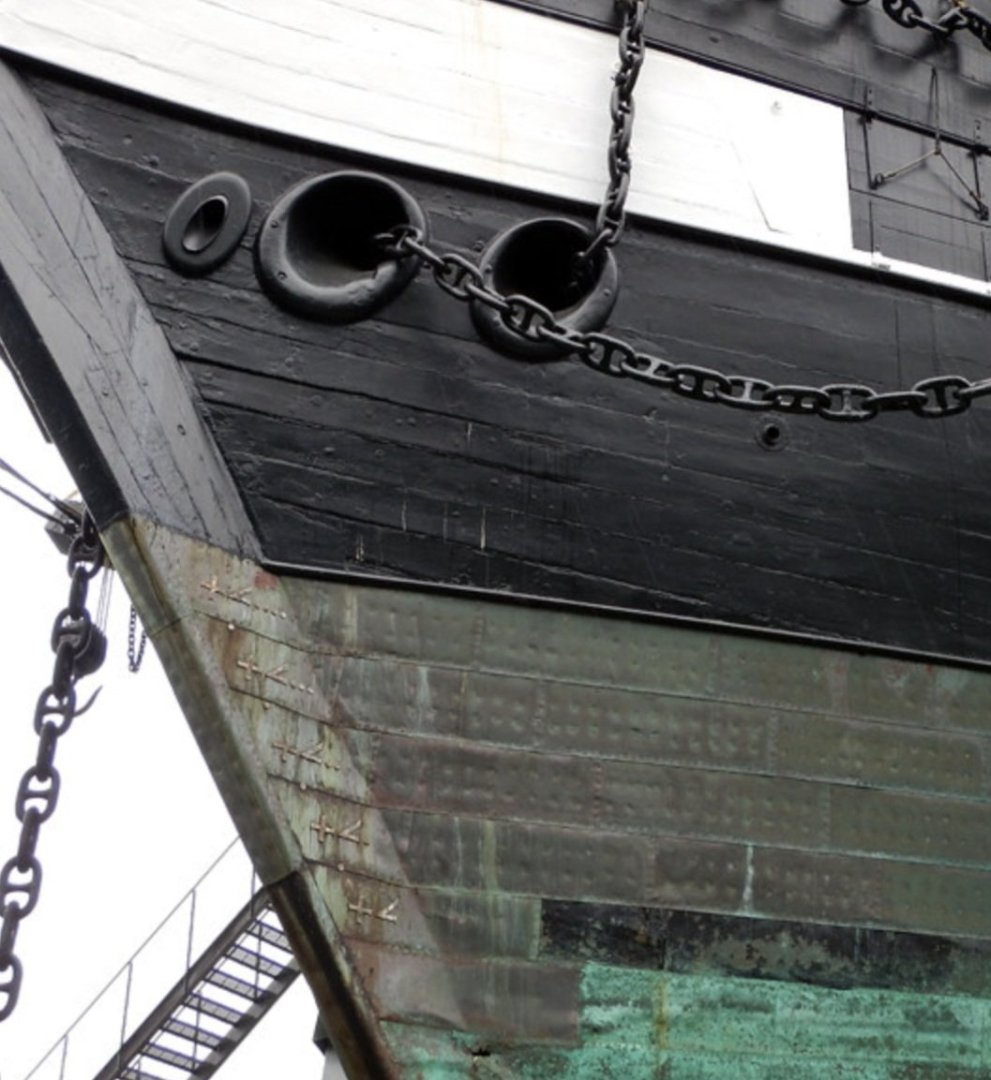
That will be a nice feature with the coppering plates. I don't know wich one is left and wich one is right. The coppering of Fregatten Jylland is symmetric.
Matthias
- GrandpaPhil and TJM
-
2
-
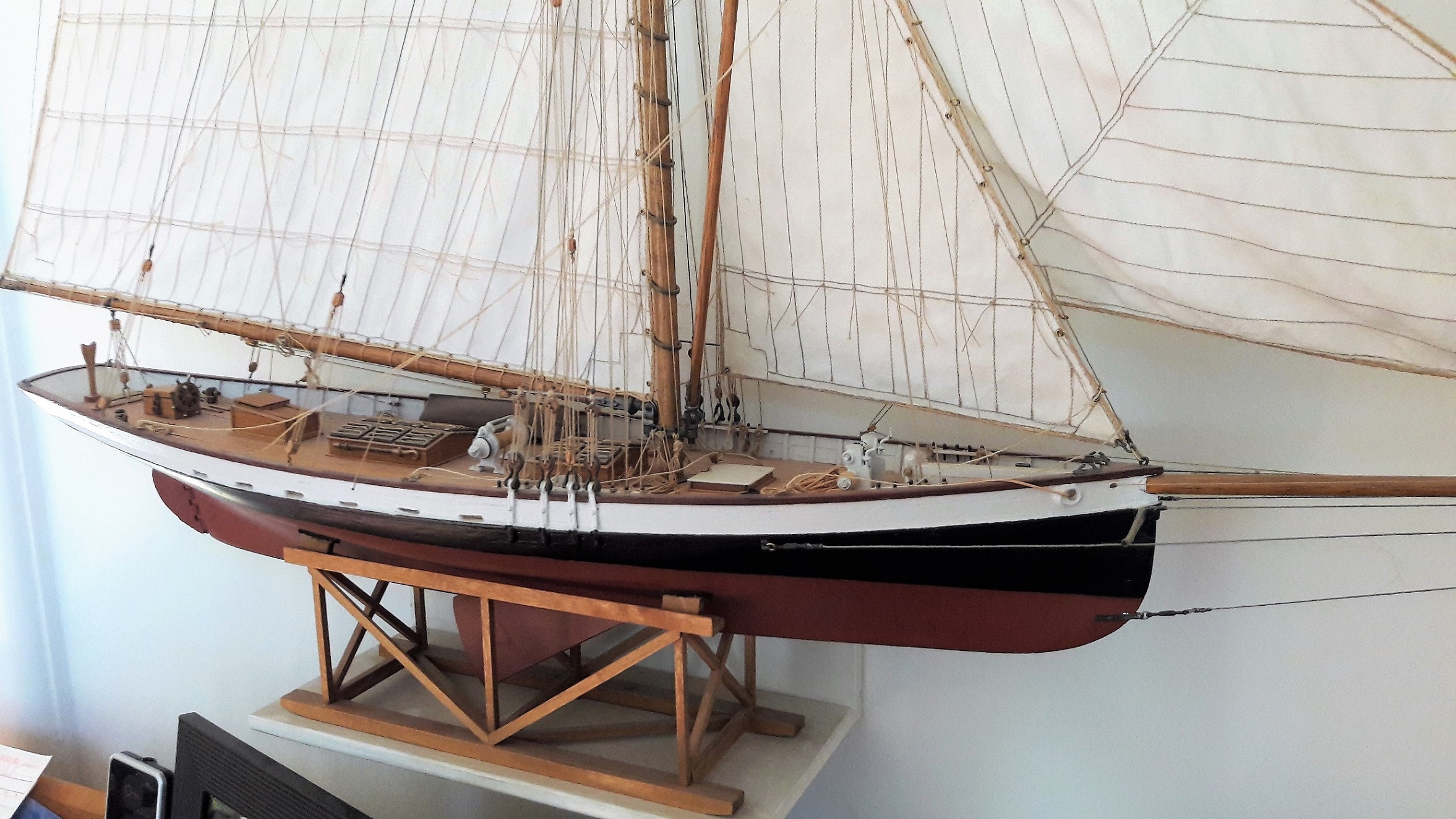
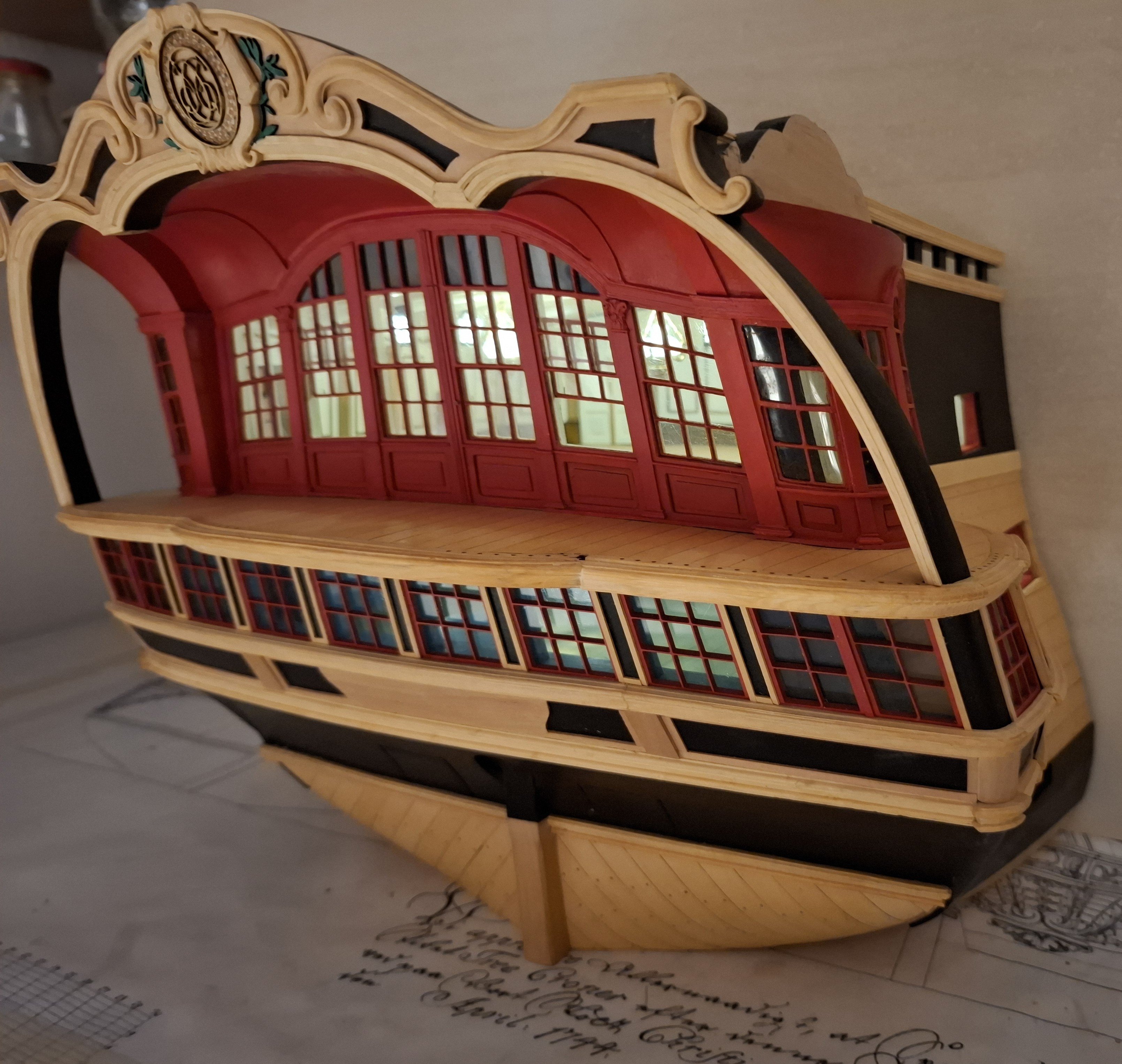
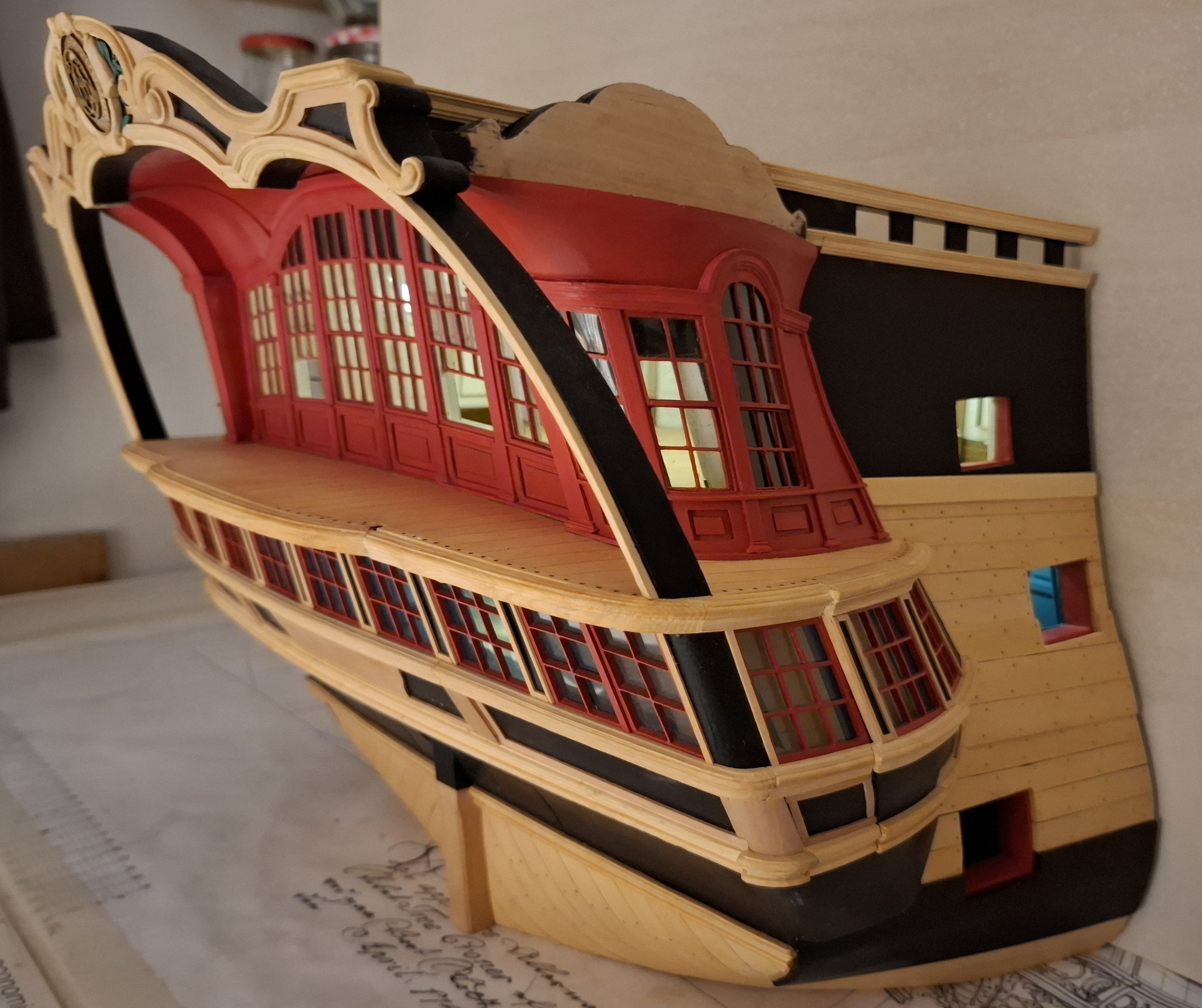
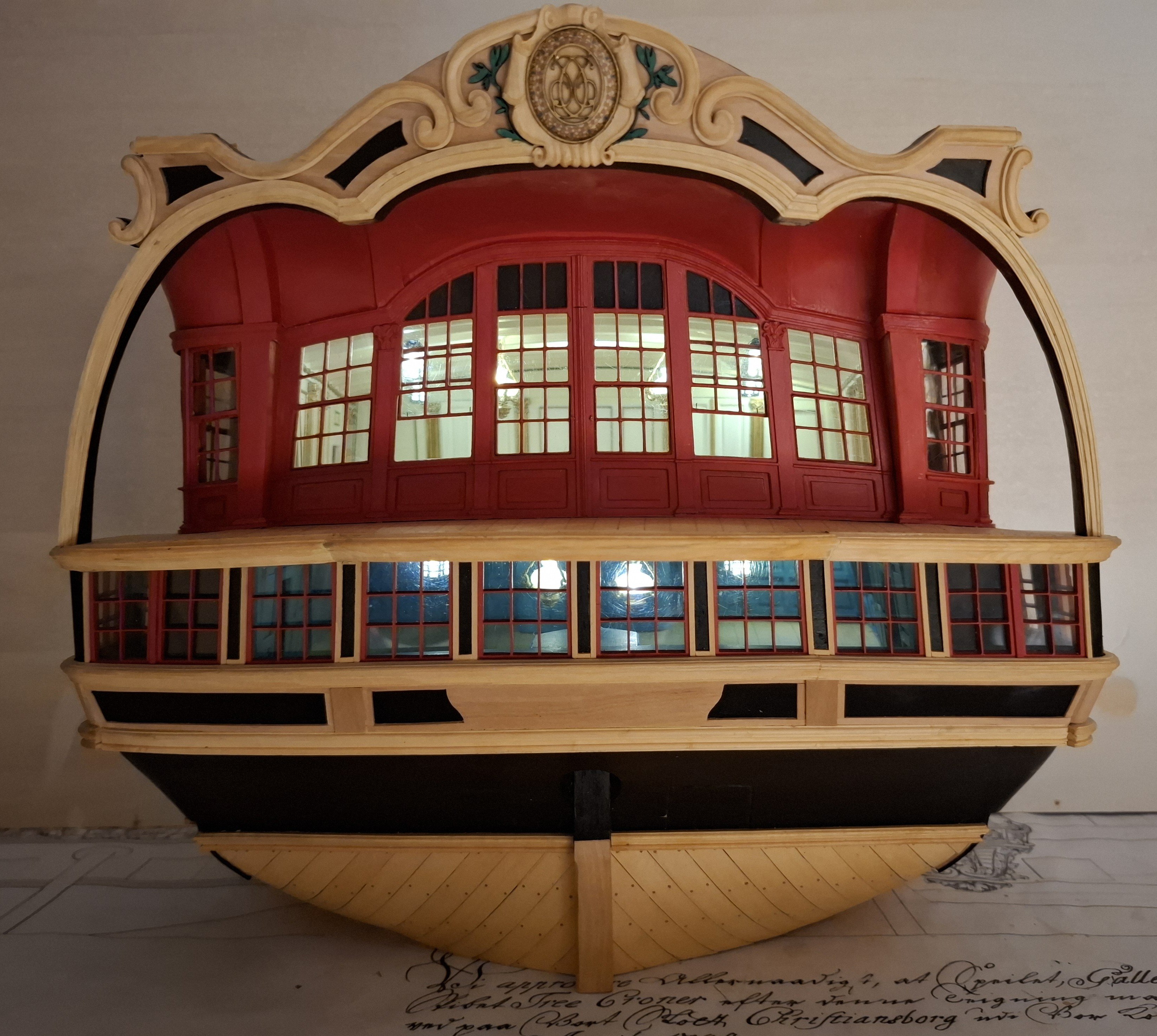
Dear fellow modellers,
After quite some time, I now have some progress to report on my part.
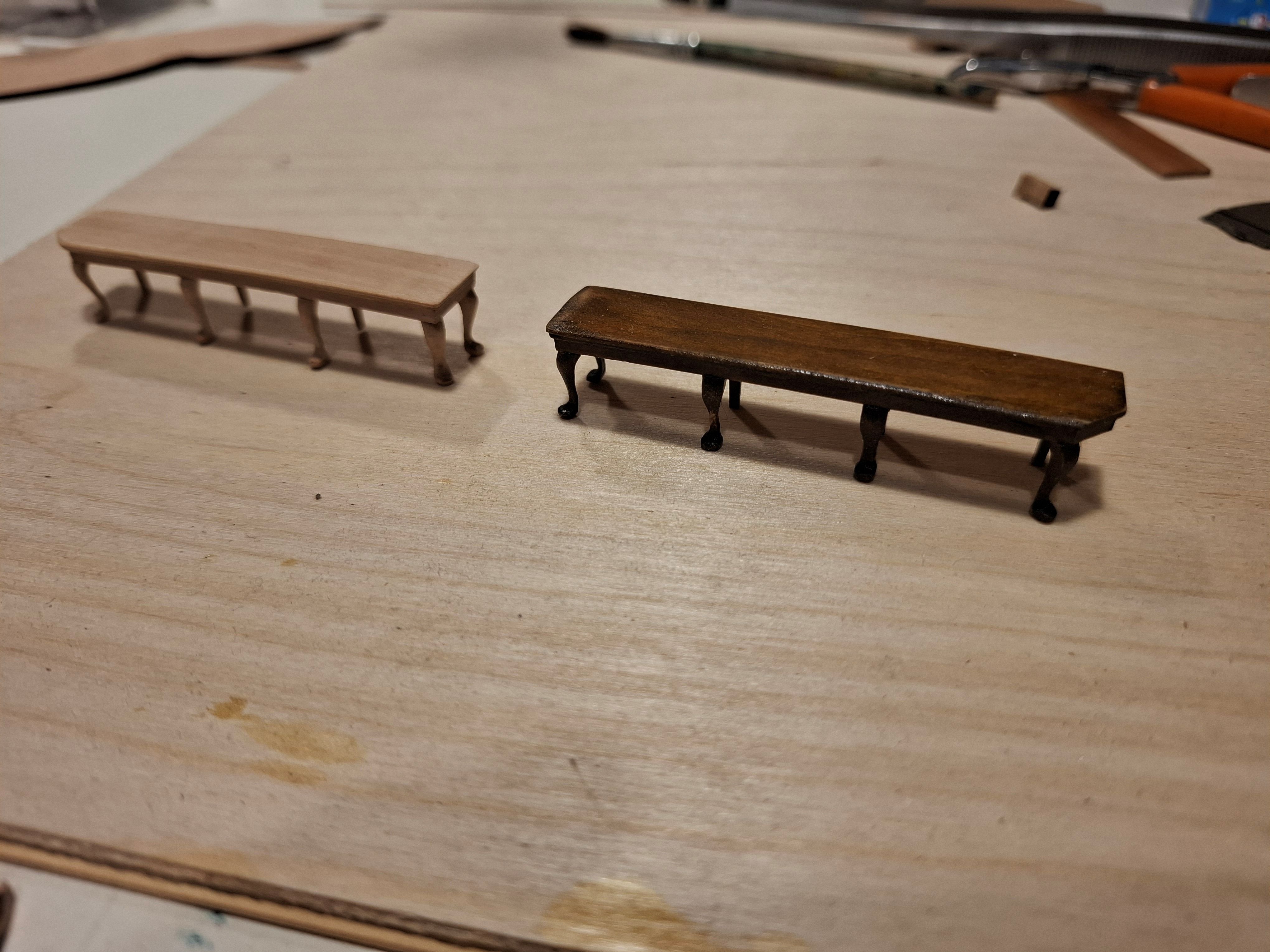
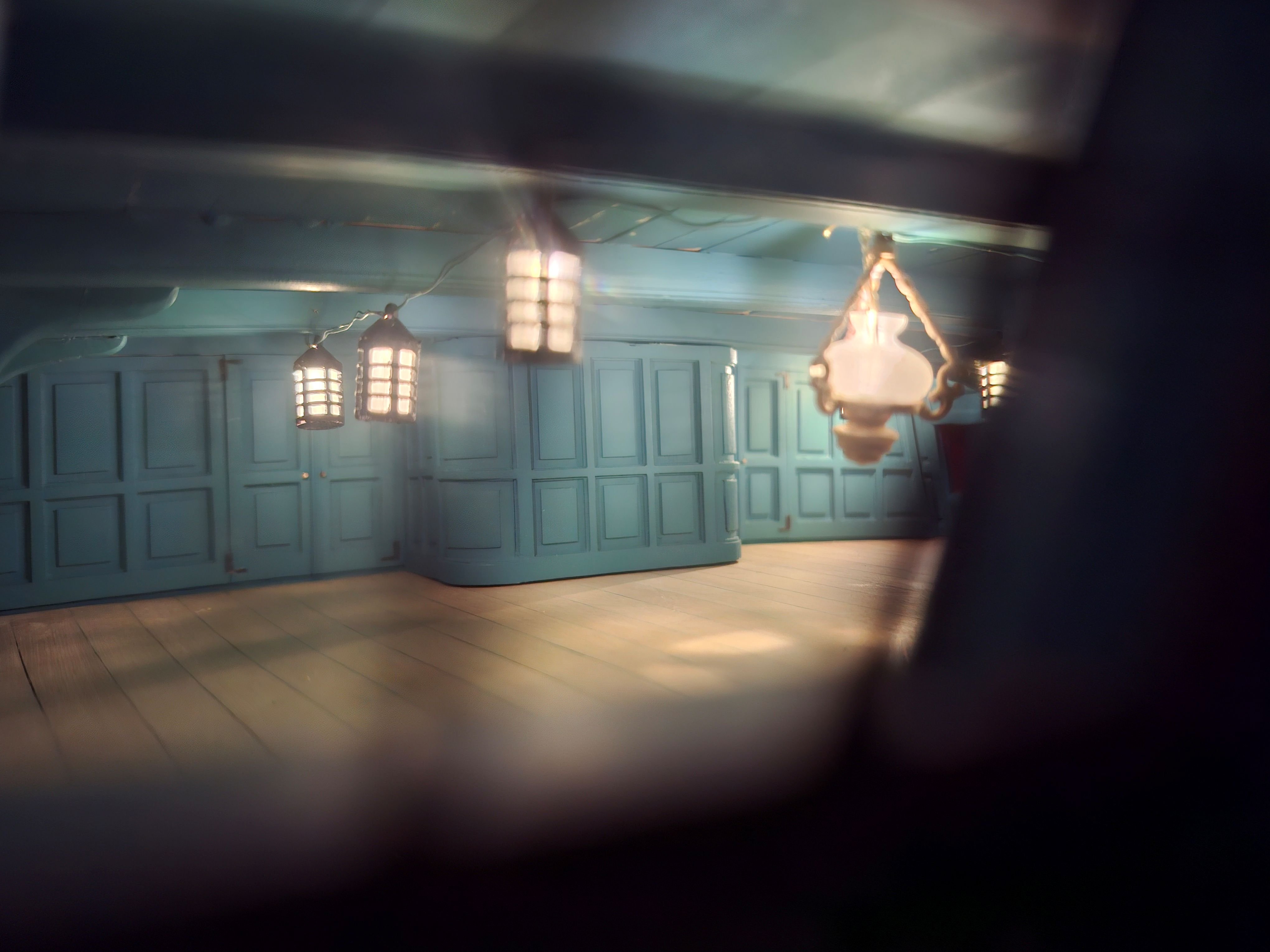
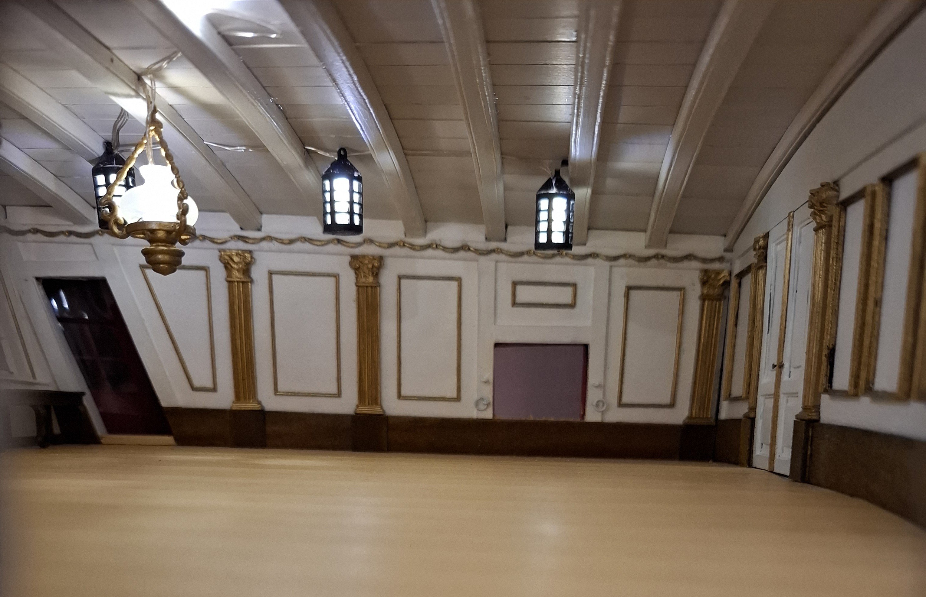
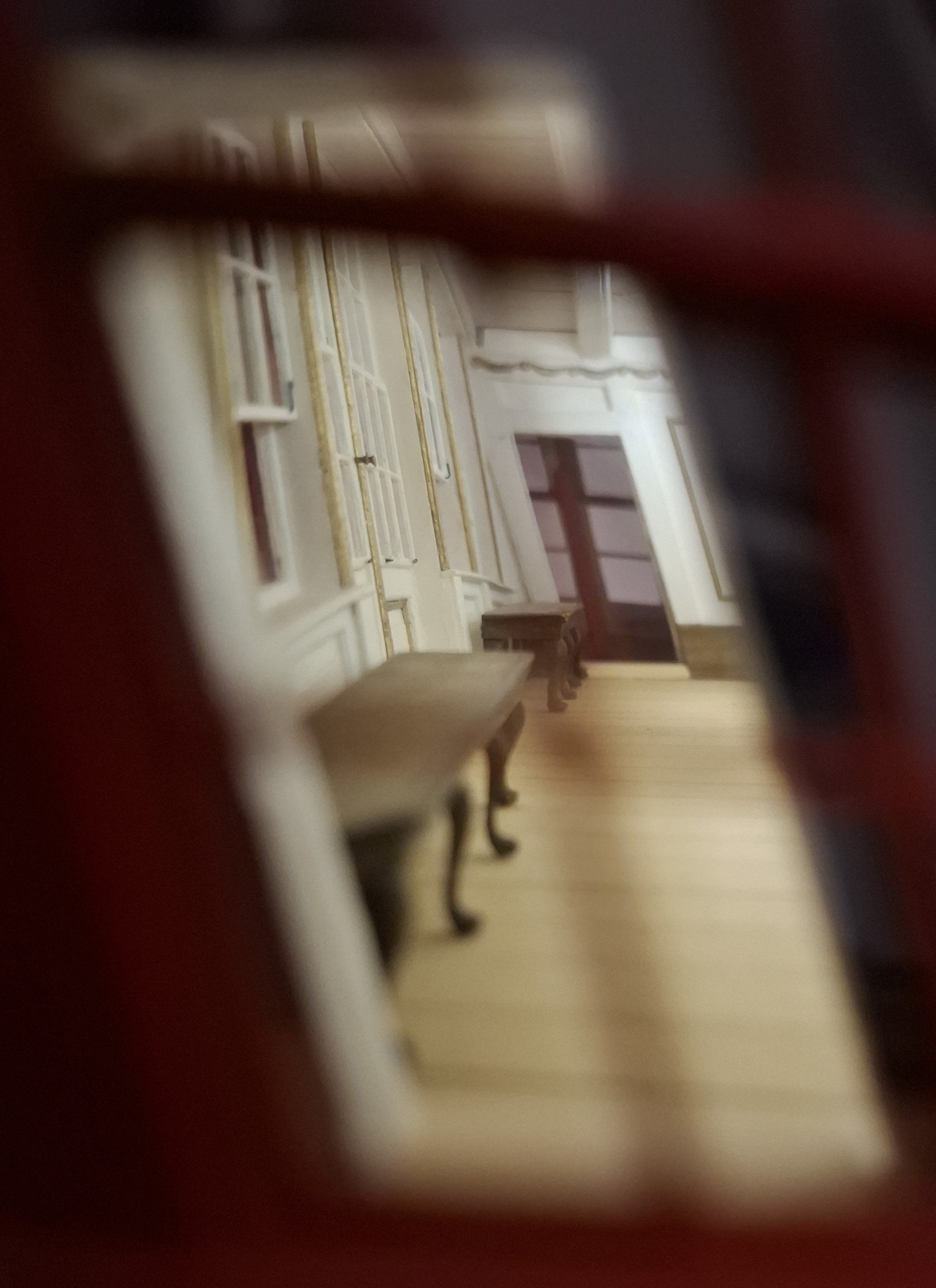
Since I am building a transom model, it will later face the viewer with its stern facing forward. I was a little bothered by the fact that when looking into the model through the stern cabins, you are looking into empty space, so to speak. To remedy this, I added a rear wall to form the missing bulkheads to the ship's interior. Below are a few pictures of the first stages of construction with the bench in front of the upper gallery windows, the deck beams and the rear wall: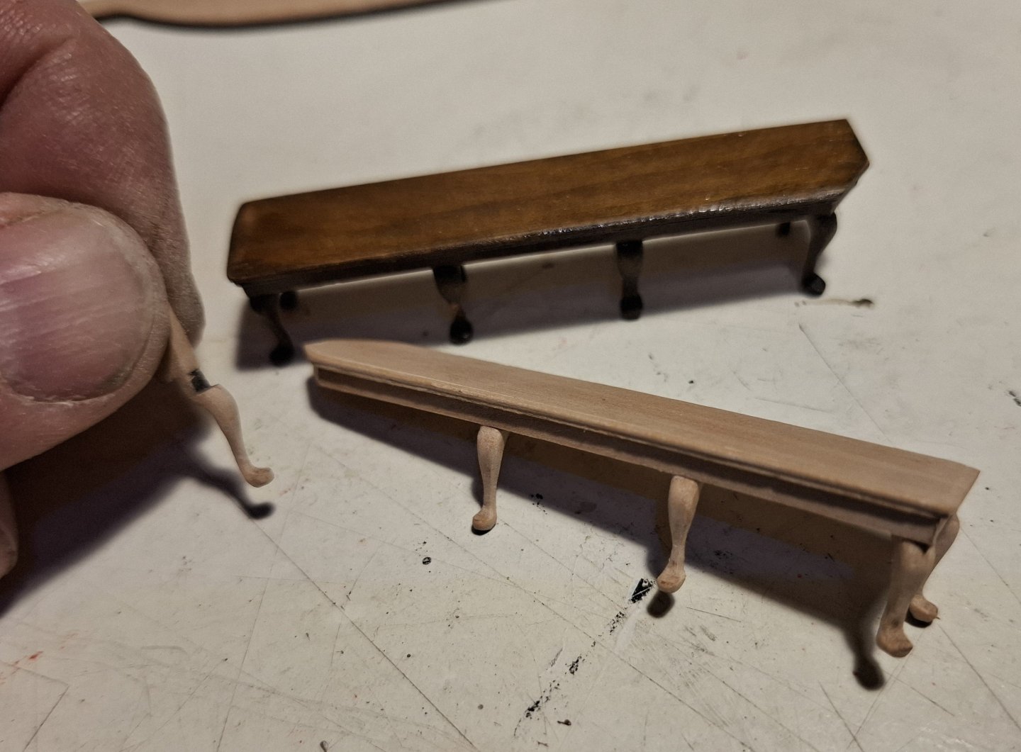


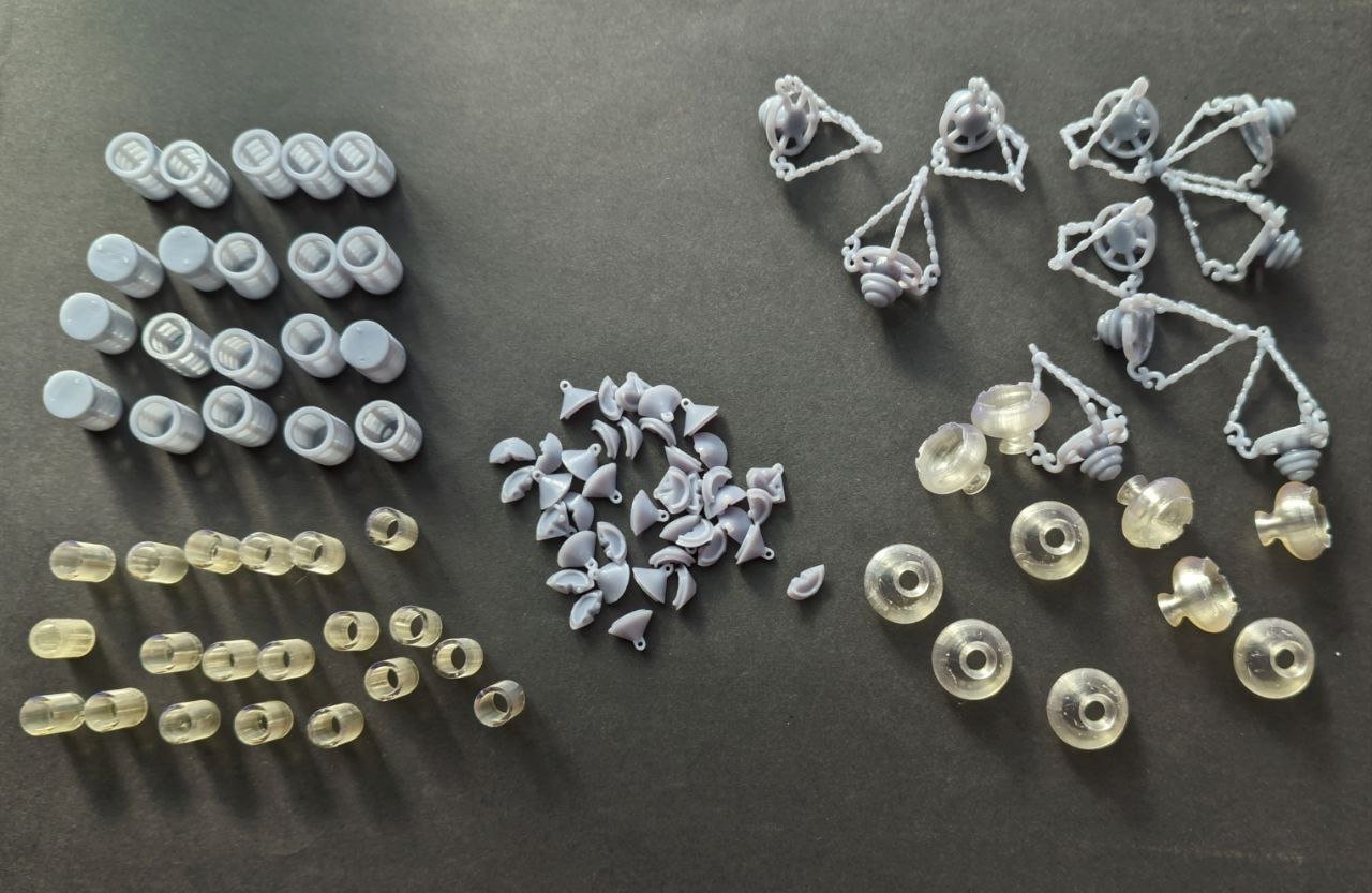
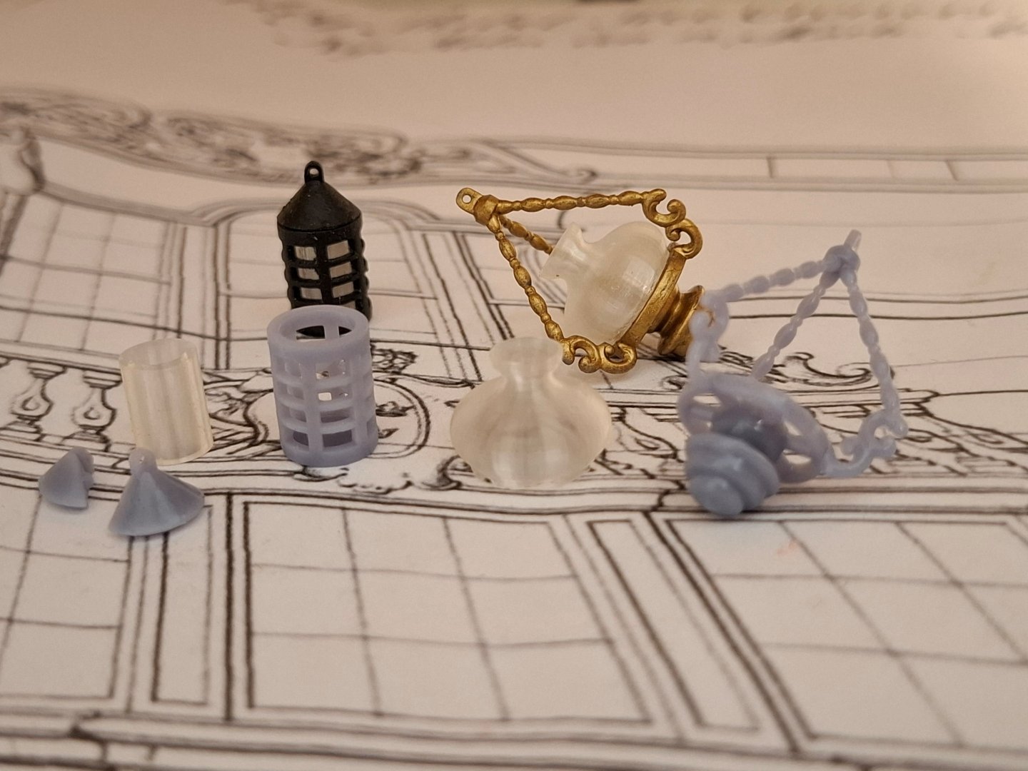
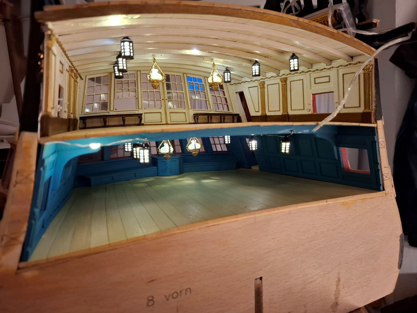
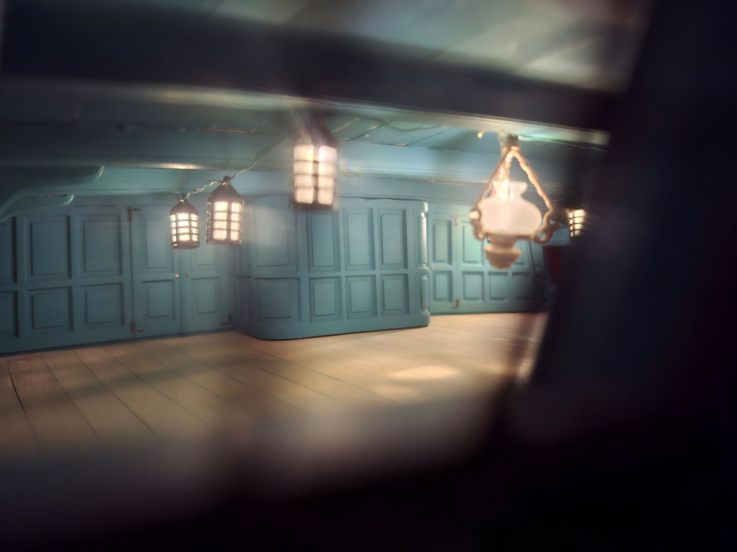
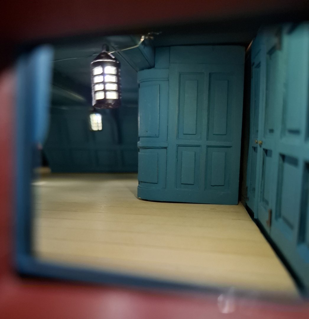
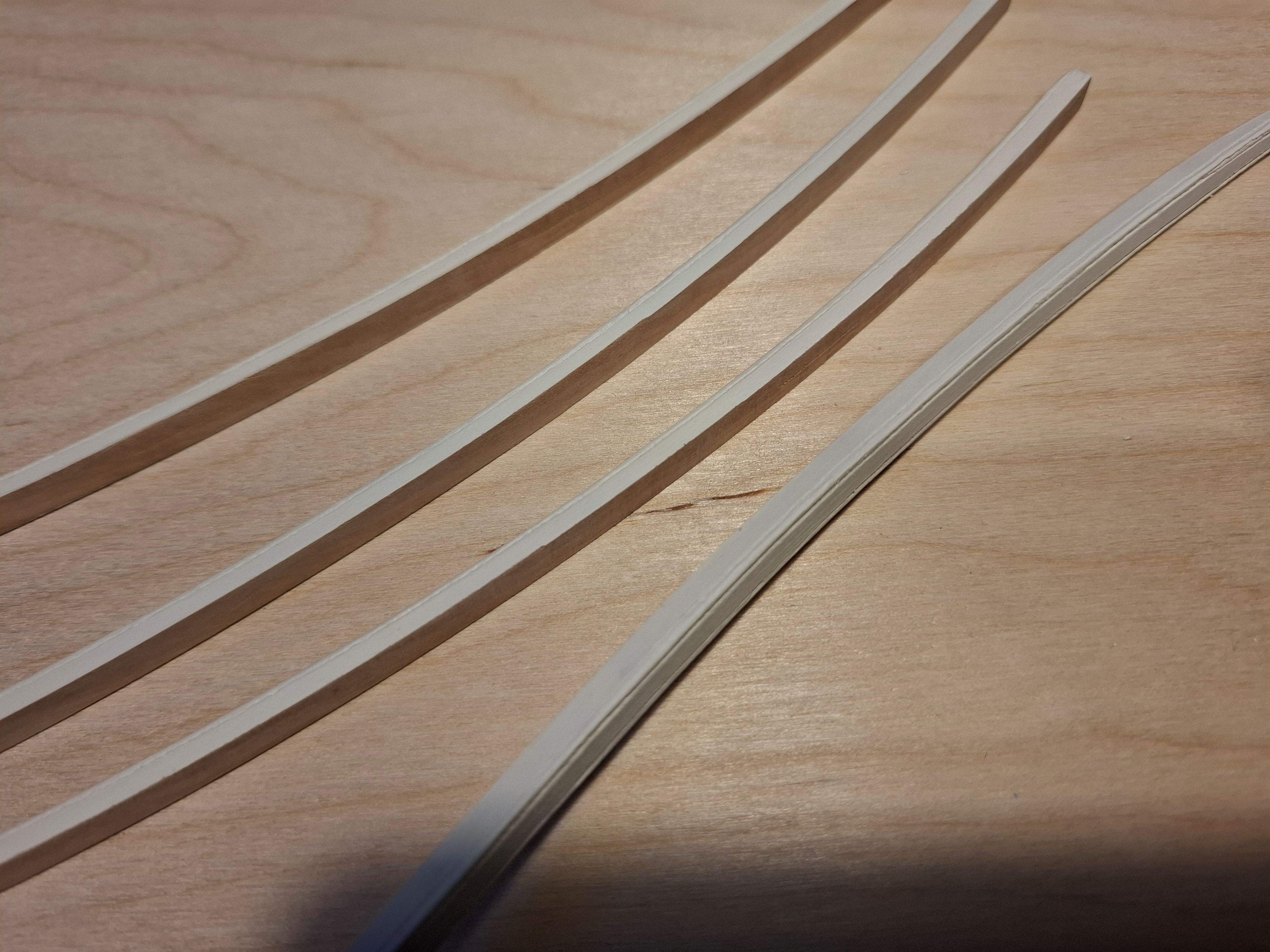
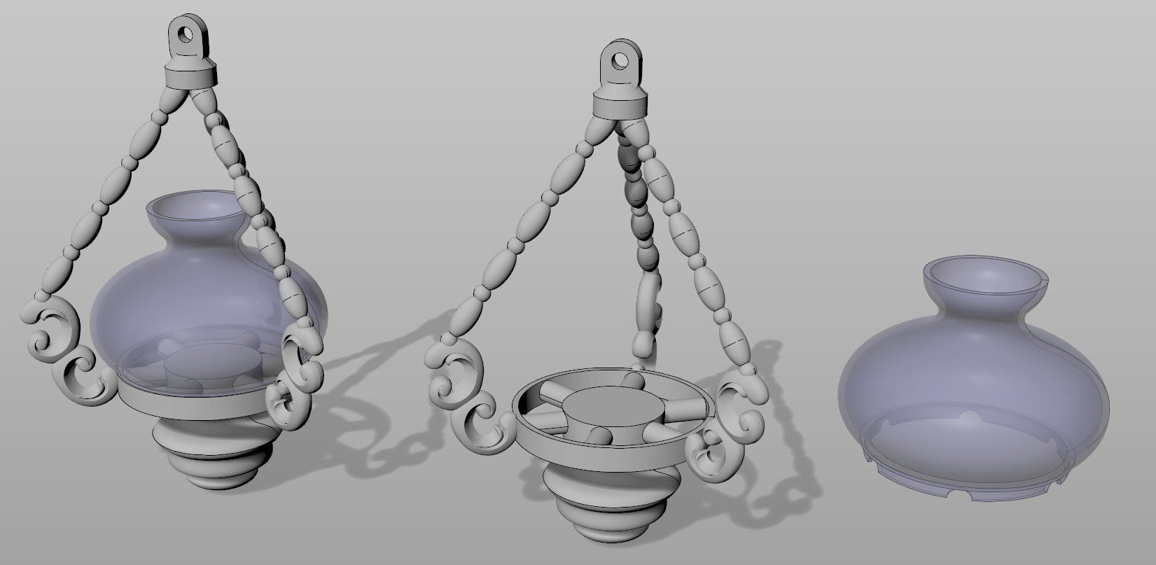
In order to get a good view of the interior later on, it was necessary to provide lighting. There are numerous options for model making here, which are more or less complicated, time-consuming and expensive. In the end, I chose the most primitive option imaginable and purchased a string of lights from Roßmann for €2.95. The small LED lights have a diameter of approx. 3 mm, very thin cables and are spaced 8 cm apart. I made a drawing of the lanterns and petroleum lamps that I had in mind as fittings and asked Igor Capinos to draw and print them in 3D, which I think he did very nicely.

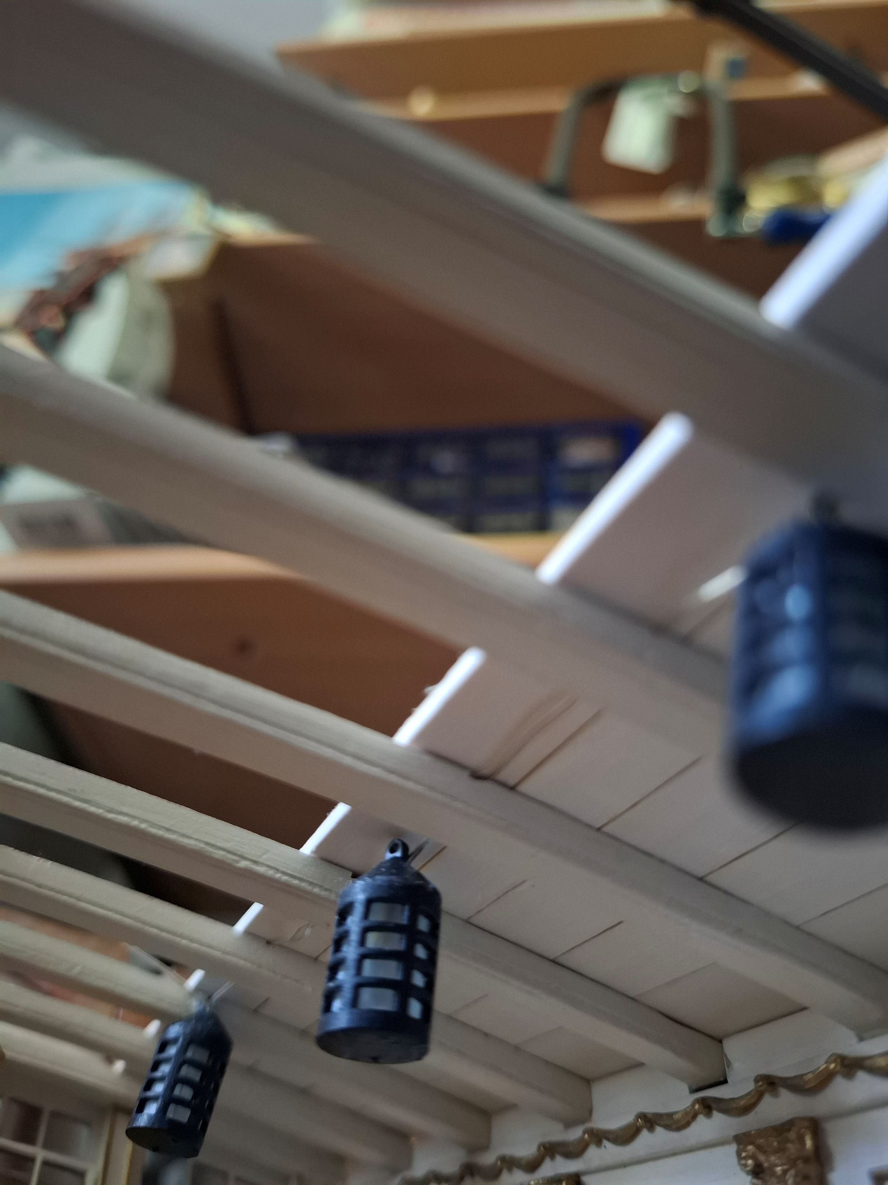
Installing the lighting in the upper part of the model went quite well, as I still had access from above, but in the lower cabin it was a compromise, as I had to run the cables under the ceiling beams, which of course is not so nice.
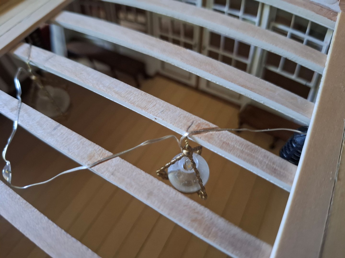

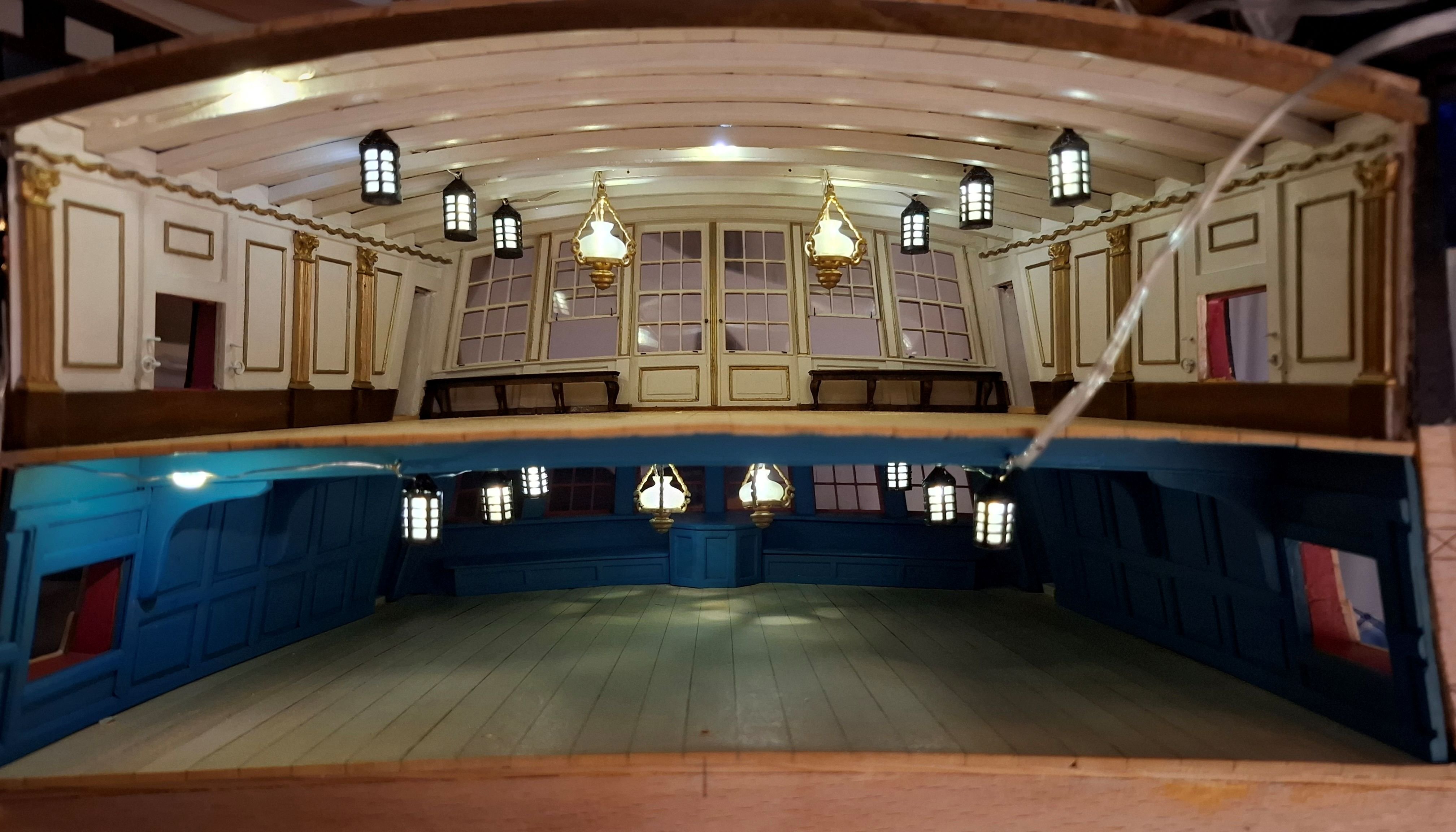
Here are some pictures of the installed lighting on both levels:

I still need to work on the fit of the rear wall here.


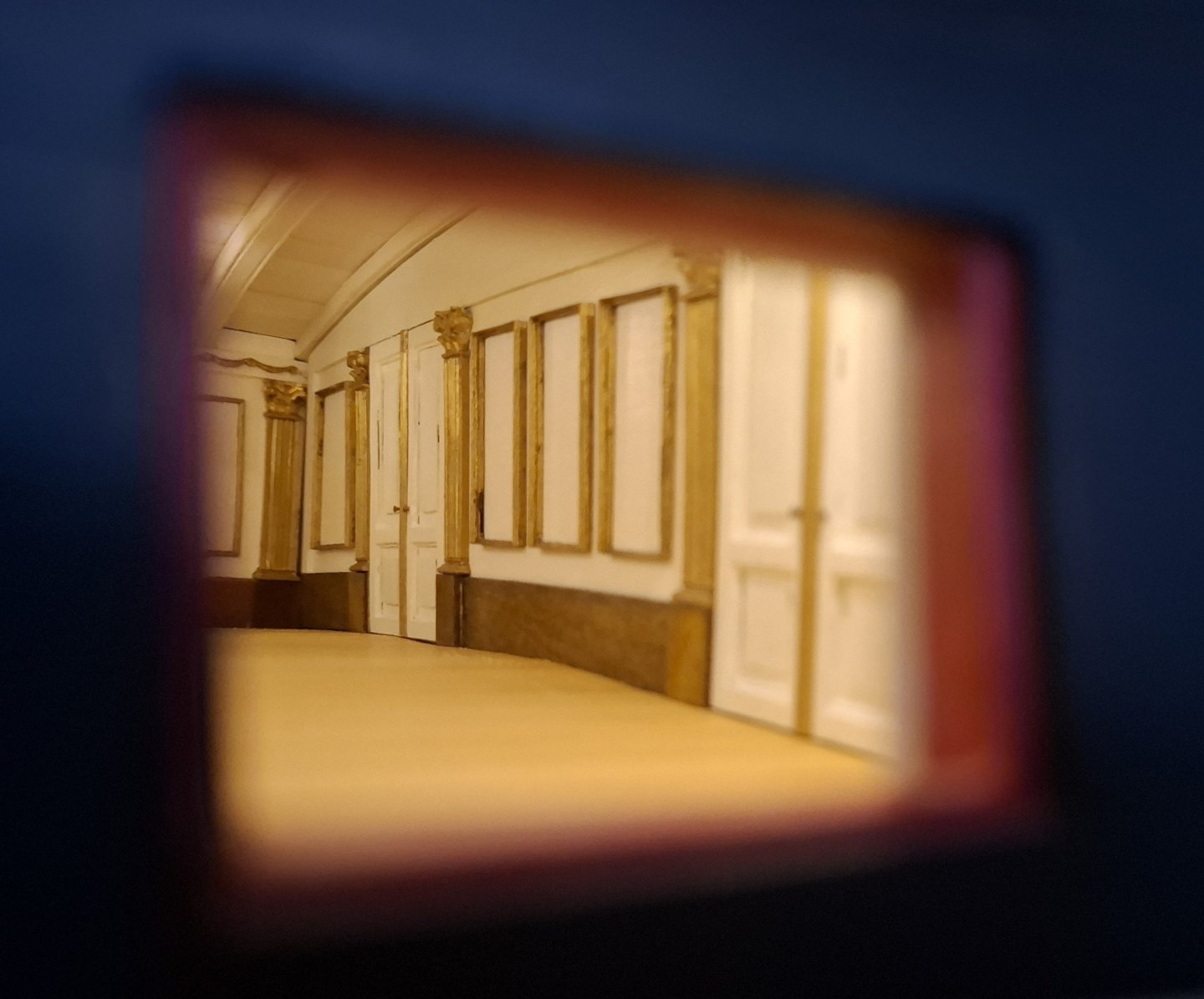
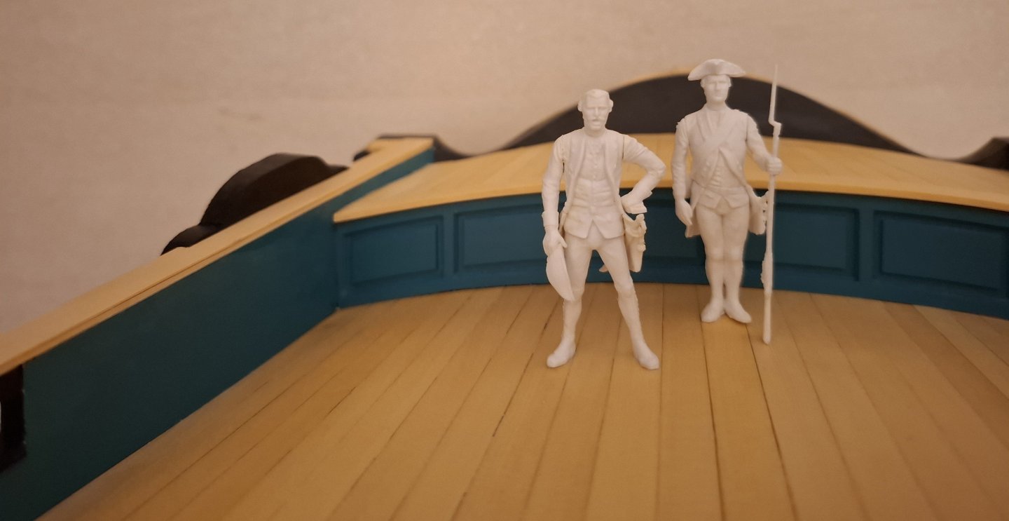
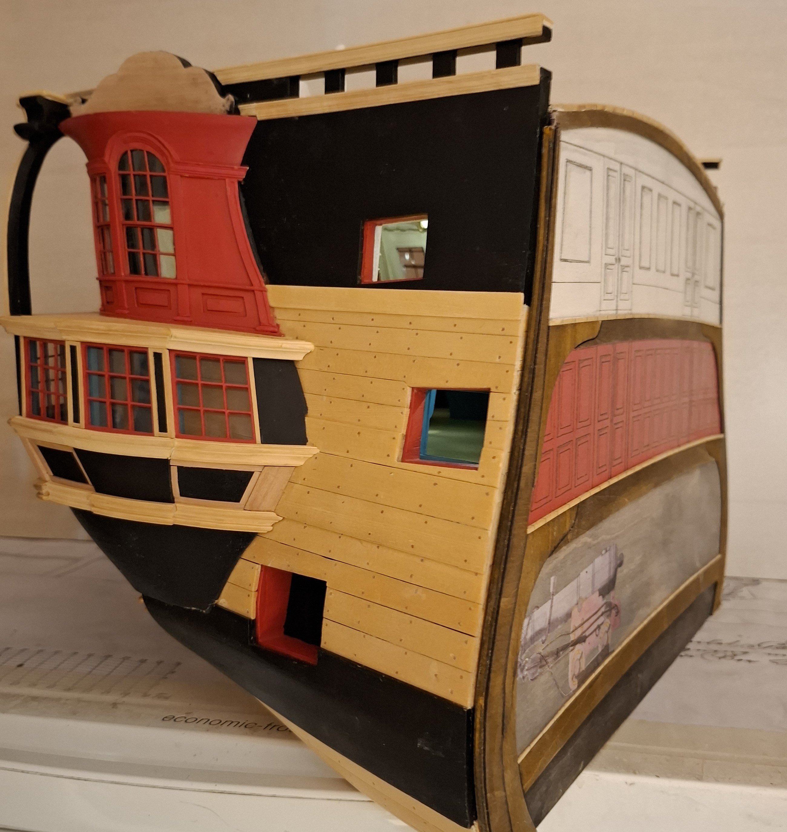
This was followed by the completion of the aft deck with the offset above the arched canopy. My design here is speculative, as the original model does not show the built state here.
I inserted a bulkhead in the front area and added a deck to the upper platform.
Later, ladder ascents and brackets for the hackboard will be added there.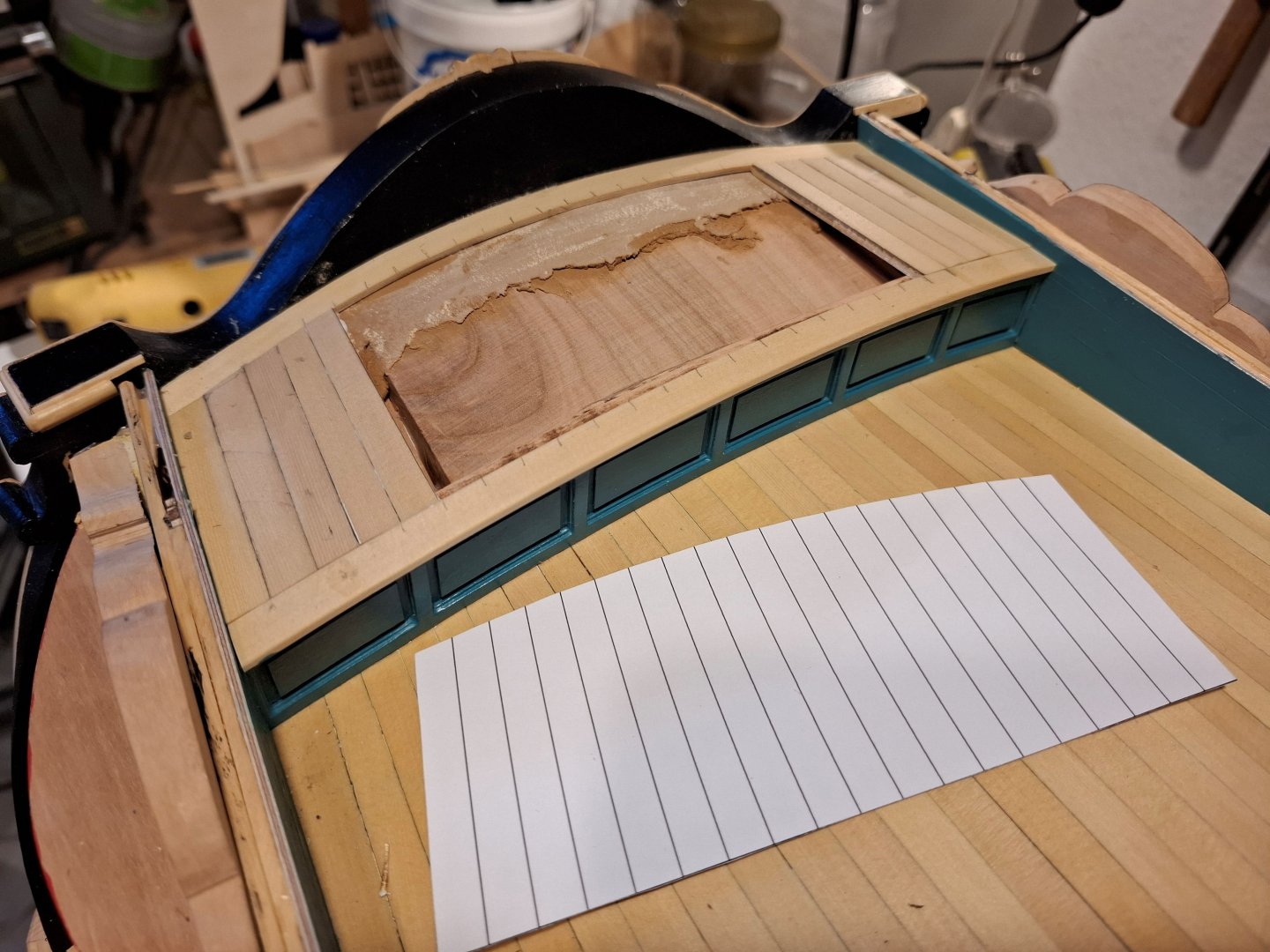
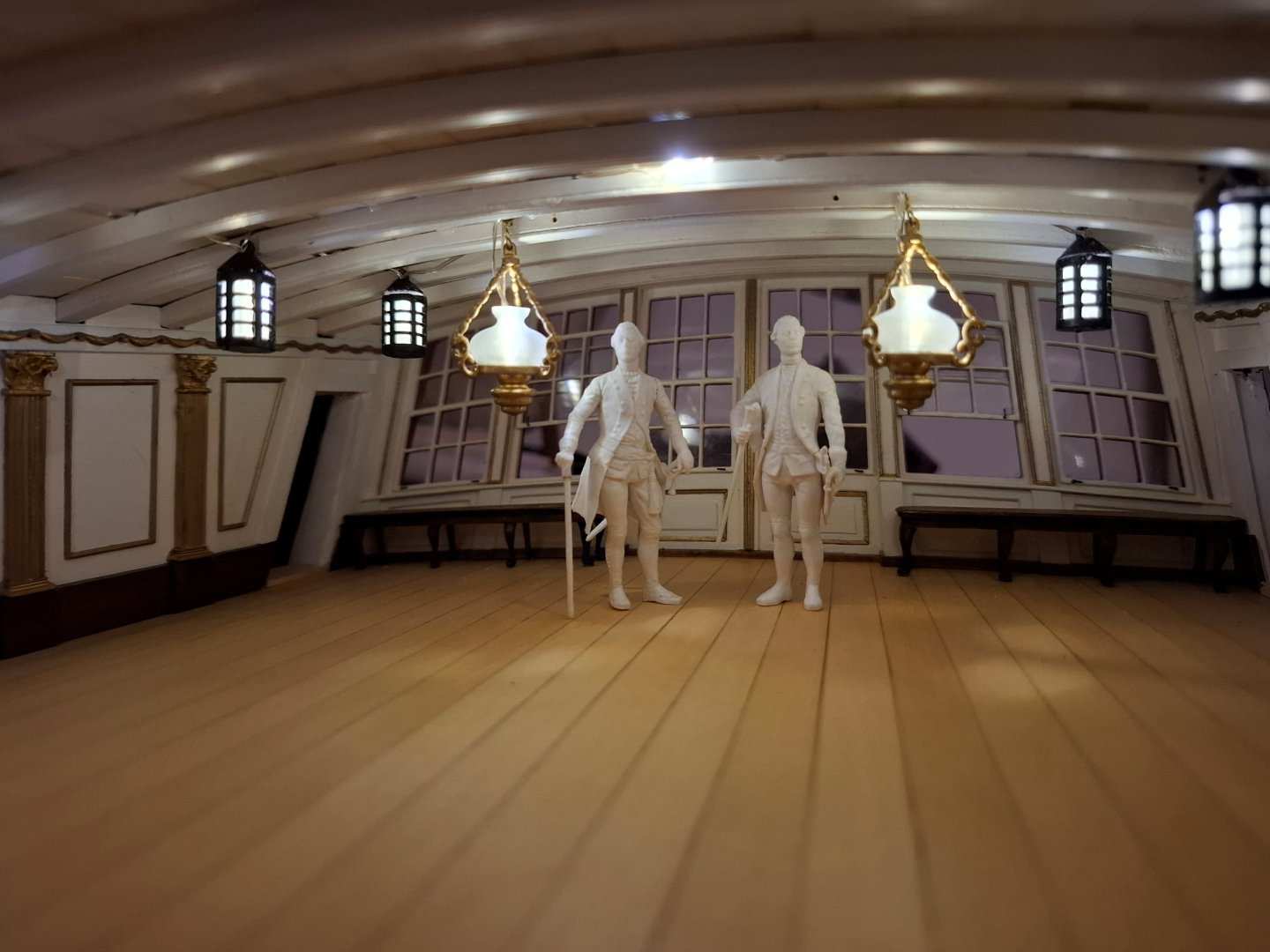
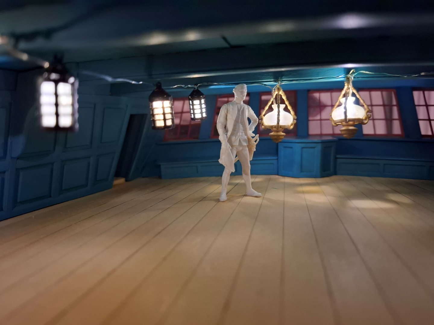
Finally, a few pictures of the overall model as it looks now.


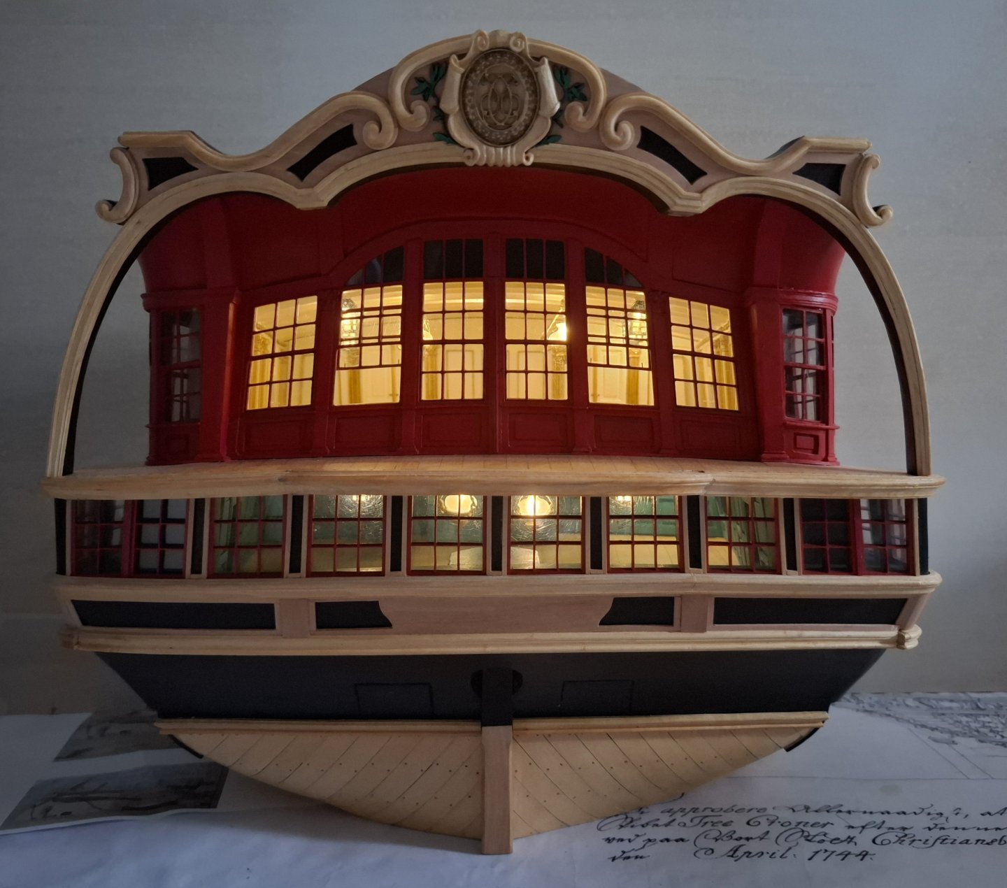
The LED-light seems to be extremely bright, that is an effect of the camera of my mobile-phone. In reality it is more warm-white.
Best regards,
Matthias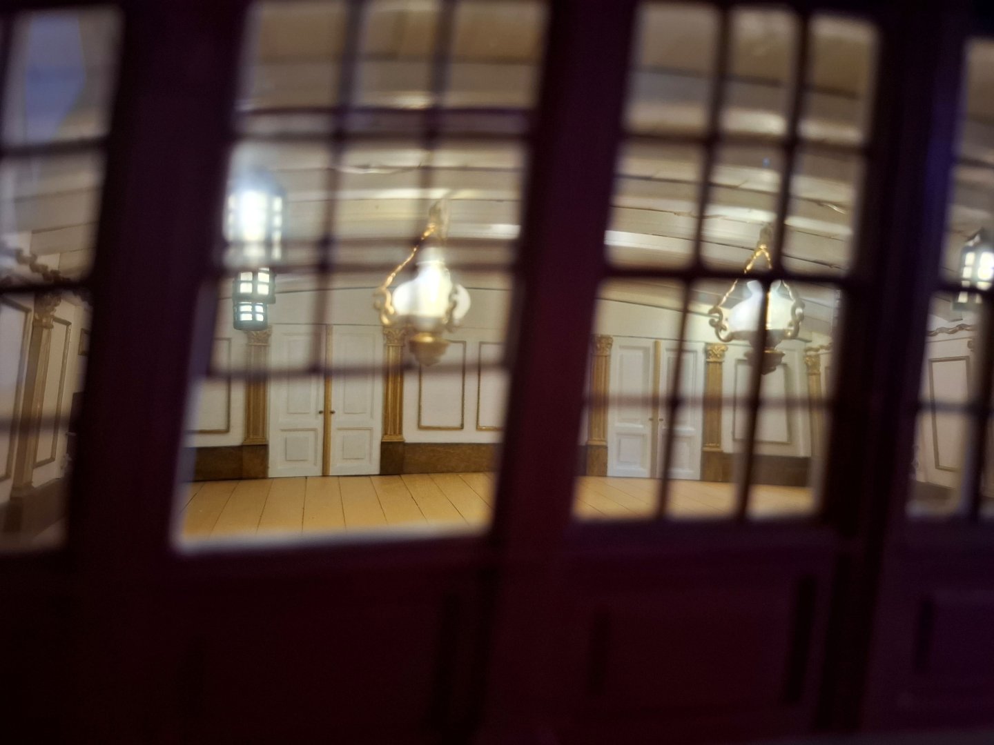
-
-
By the way, do you know this painting of Lüder Arenholt? Elben is the Schoner on the left side.

This picture from Wikipedia you might know as well:
.jpg.25b28dd5cf210686033423295de6485a.jpg)
and there must be this model somewhere in Denmark.
These pictures by Julius Prömmel are interesting as well.
.jpg.ddc446750d4f89b877d55484a548aa40.jpg)
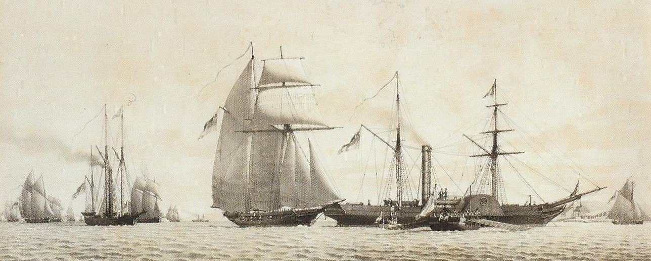
Elben in the center of the painting.
Matthias
- GrandpaPhil, TJM, Thukydides and 2 others
-
4
-
1
-
-
Hi Ben, you are making a great Job on this model!!! I have a question. Is it necessary to glue the keel onto the model so early? Maybe it is easier to fair and paint the frames without the keel and stem on it.
Matthias
-
Hi Frank, I didn't look in here for a while, great progress!! Building the great cabin is so much fun! I enjoied that part a lot, when I built my Winchelsea.
Matthias
- CiscoH and FrankWouts
-
2
-
Really nice design! Well done. You should offer this as a kit, once the prototype is finished.
Matthias
- TJM and hollowneck
-
1
-
1
-
Thank you for your nice comments and likes.
Thorbjørn (TJM), the photos you made for me from the original model at the museum in Copenhagen made it possible to understand the construction much better then by just looking on the plans and the two photos, wich are public available. So thank you again for your help. I will visit Copenhagen this summer and am looking forward to have a look at the original model myself and all the other wonderful models of the Danish Navy.
Matthias
-
Dear fellow modellers,
thank you all for your comments and likes.
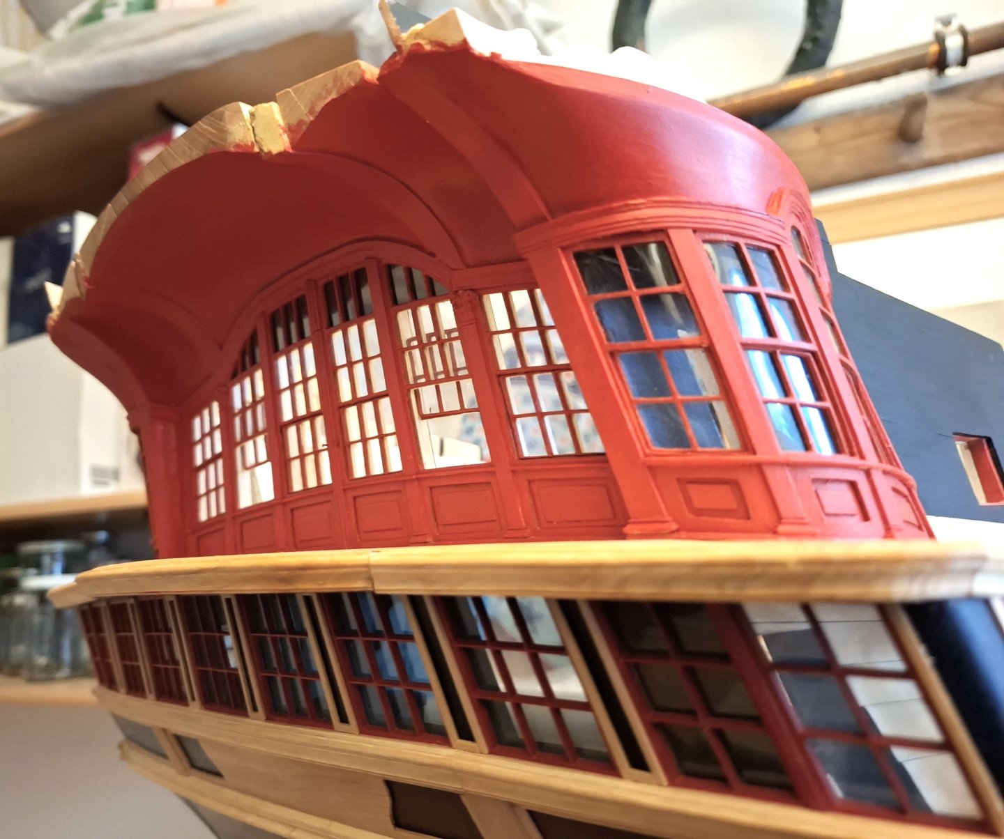
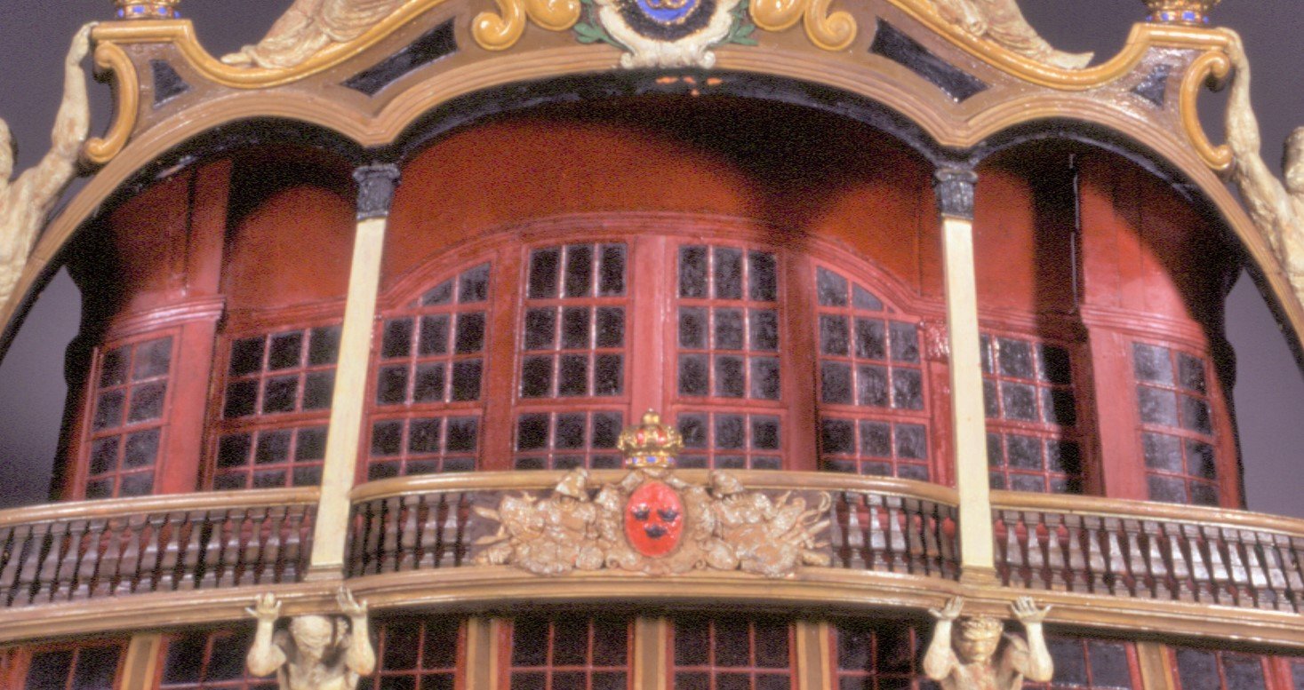
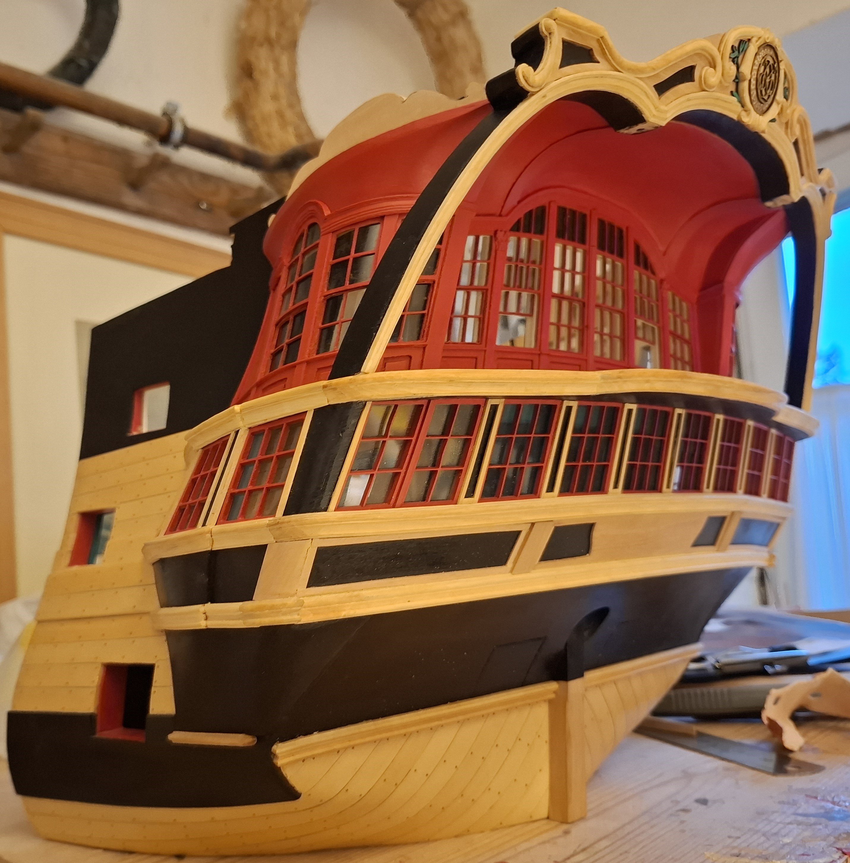
Over the last few days I have been working on the canopy above the stern gallery.
It is an imposing vault, interrupted by four supporting ribs, which swings upwards from the window front of the main cabin almost like a domed vault in a church and then descends again on the inside of the transom arch to end there. All in all, a beautiful but, in my opinion, somewhat unusual construction that raises several questions.
First question: How was the vault constructed?
Second question: As it protrudes very far above the aft deck, how was the poop designed here?
Third question: What might the ship's carpenters have been thinking when they were asked to build it? They probably rebelled at first.
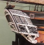
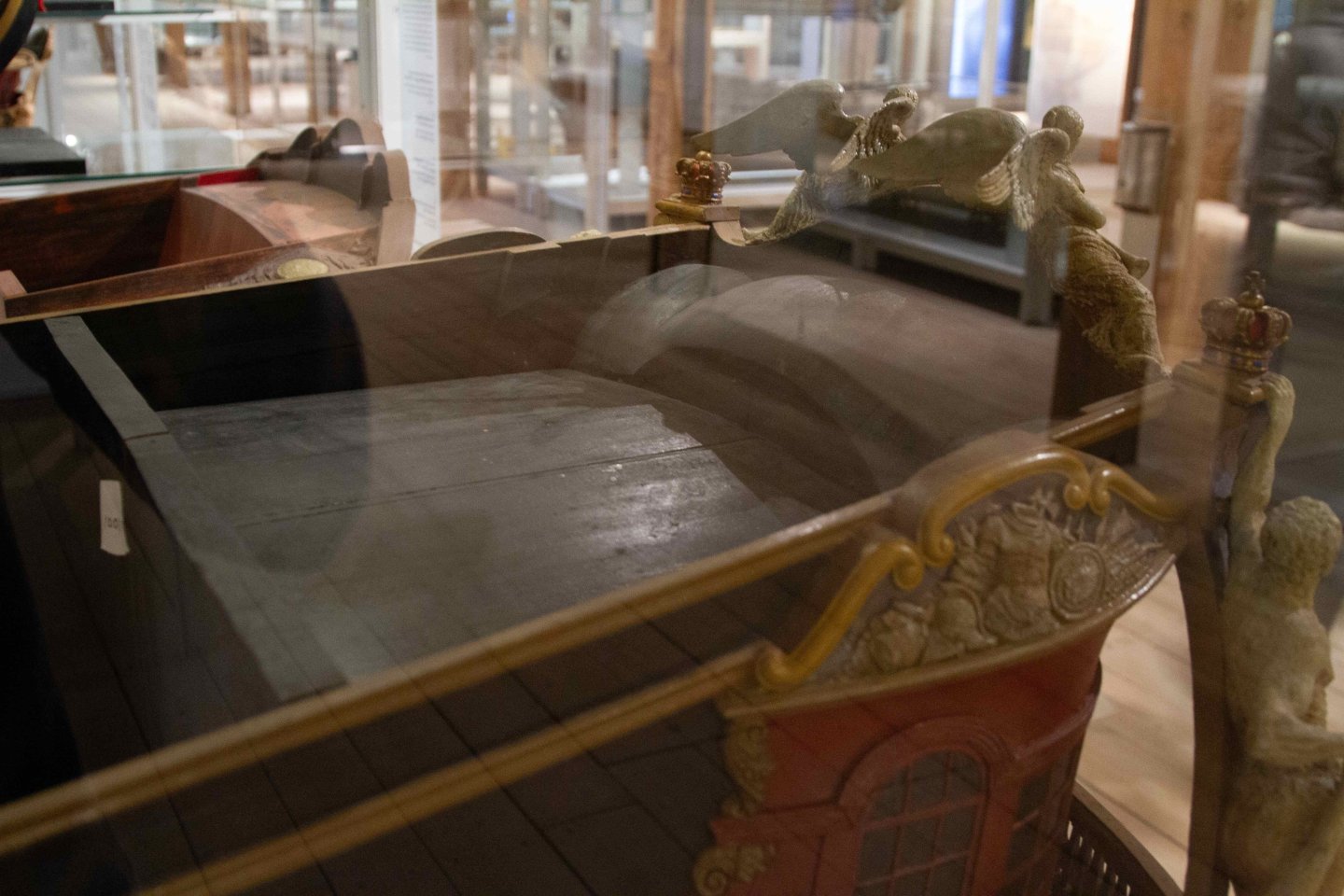
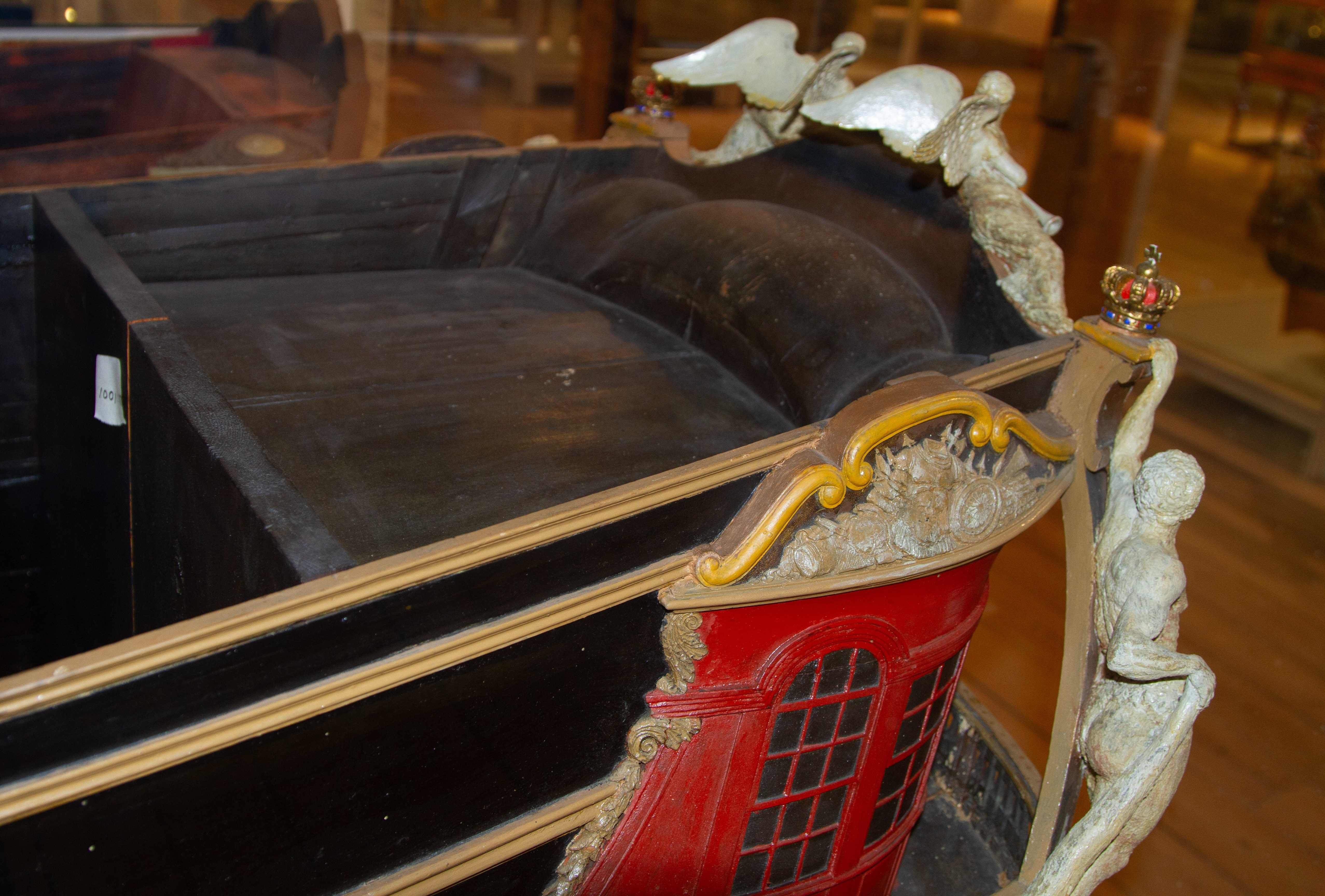
I'll start with a few photos of the original model to illustrate the problem: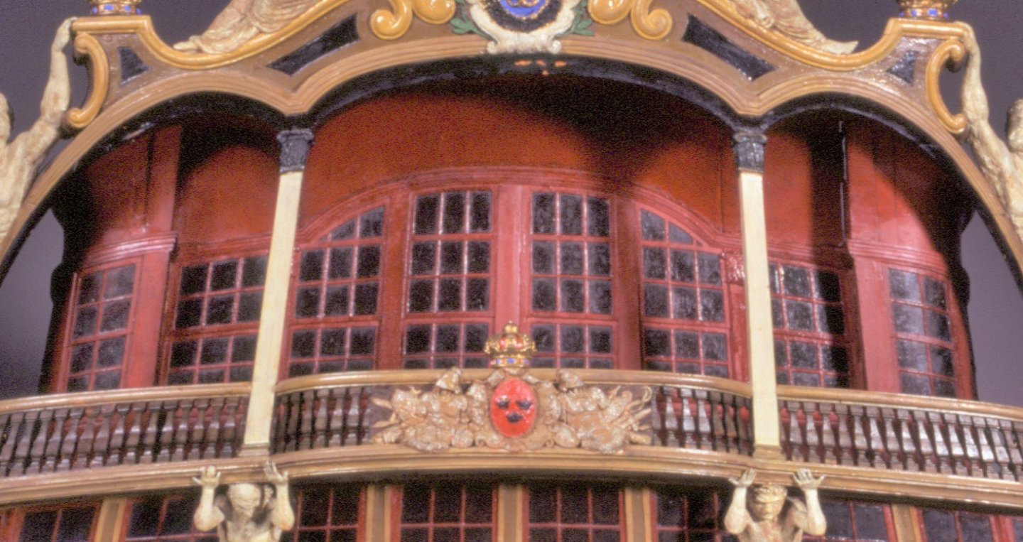
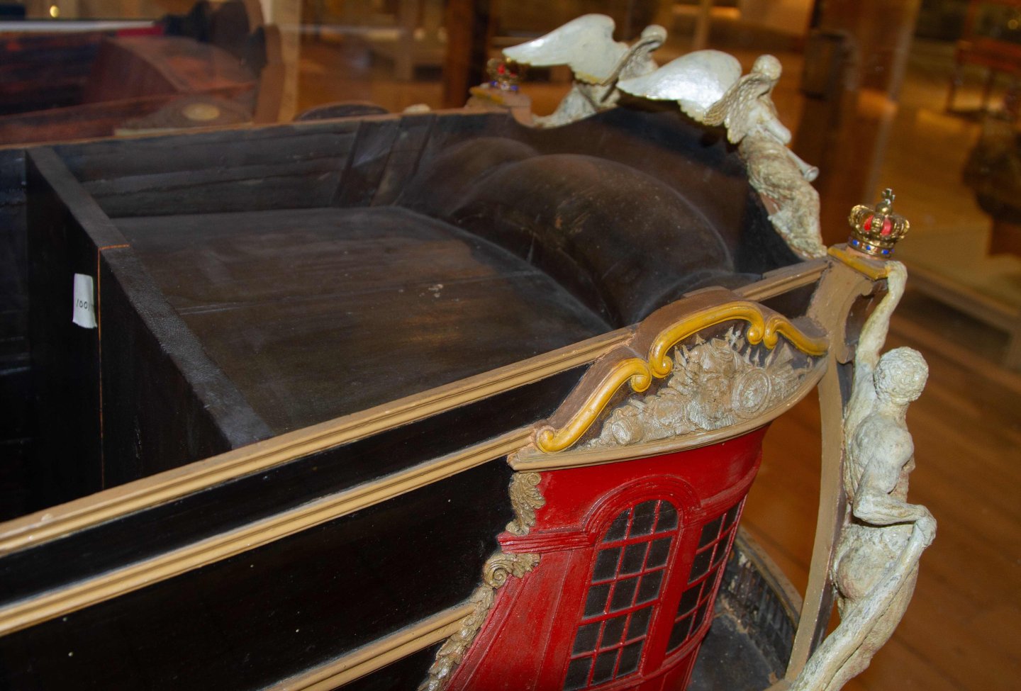
You can see here that in the model the vault shell has obviously been carved out of a block and fitted into place. You can also see in the last picture how far the vault protrudes above the poop deck.
There are some historical models and drawings that show vaulted canopies over the stern gallery, but not to these dimensions.
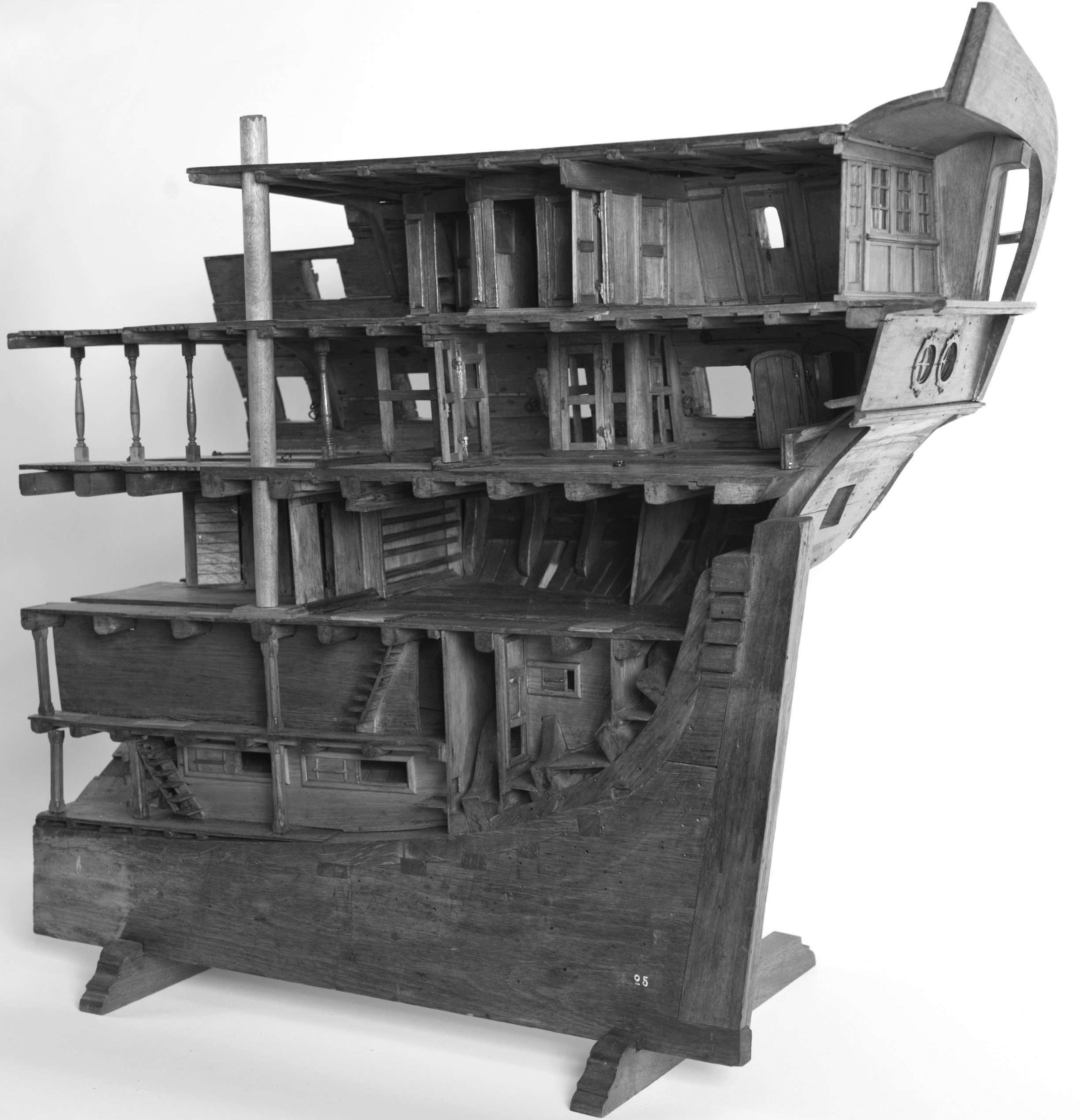
Here are two pictures of the stern model of a Swedish ship of the line from the first half of the 18th century:

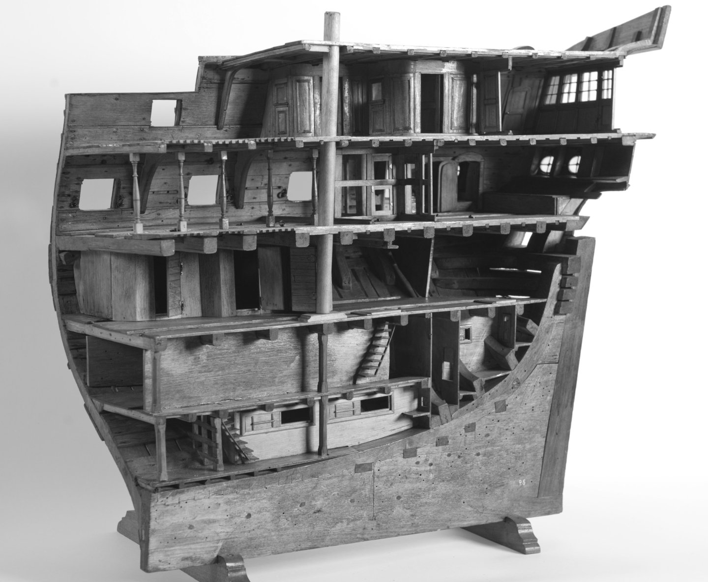
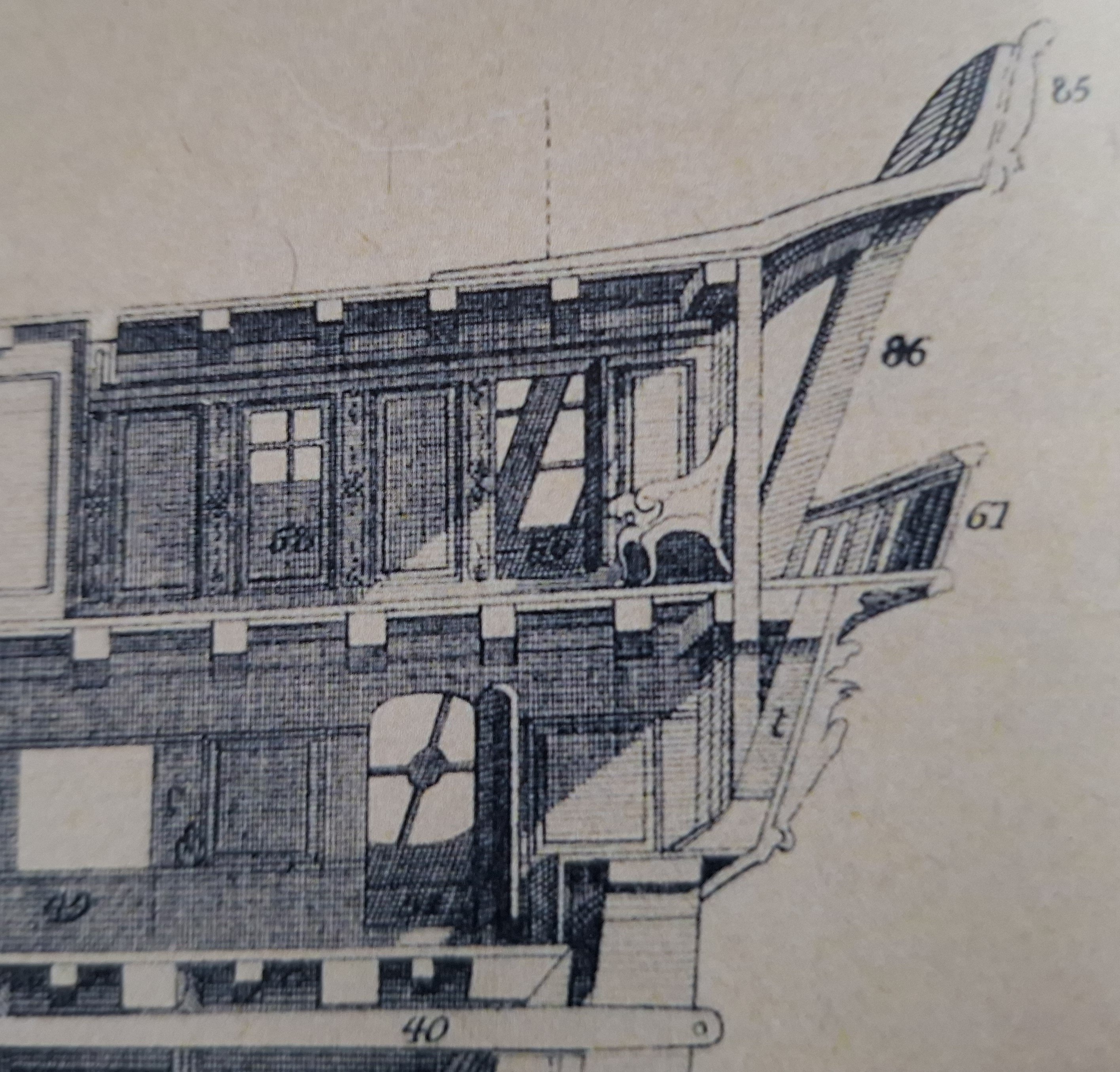
and the drawing of a French ship of the line, also from the first half of the 18th century:

Both show the end of the poop deck above the window front and a construction of knees supporting the canopy and reaching up to the transom.
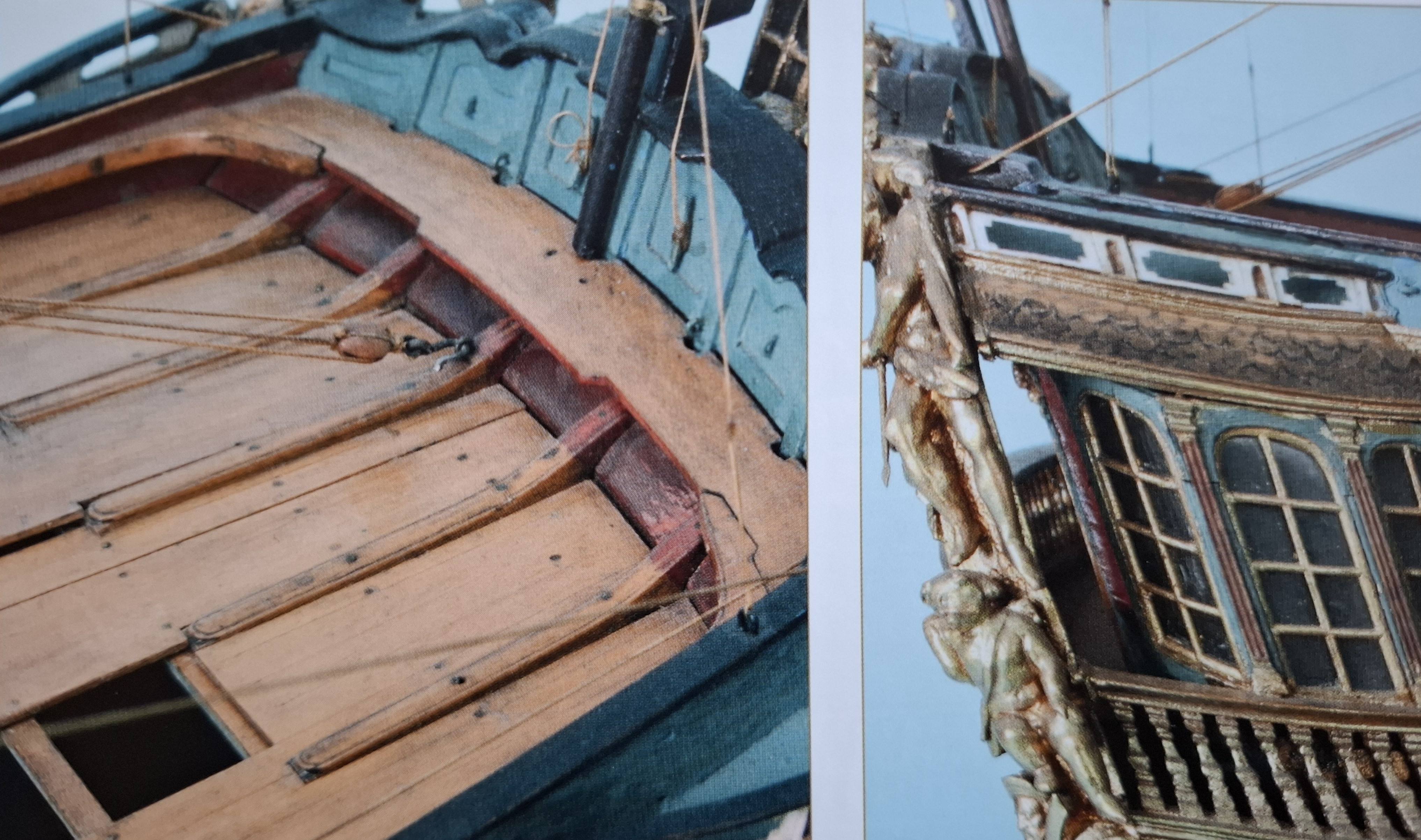
This is exactly what this English ship of the line from 1735 looks like.
Here you can already see a solution for a raised deck level above the canopy; I will end up with something similar.
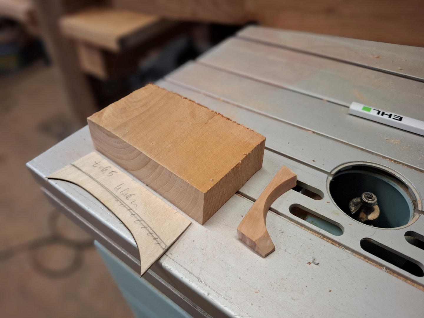
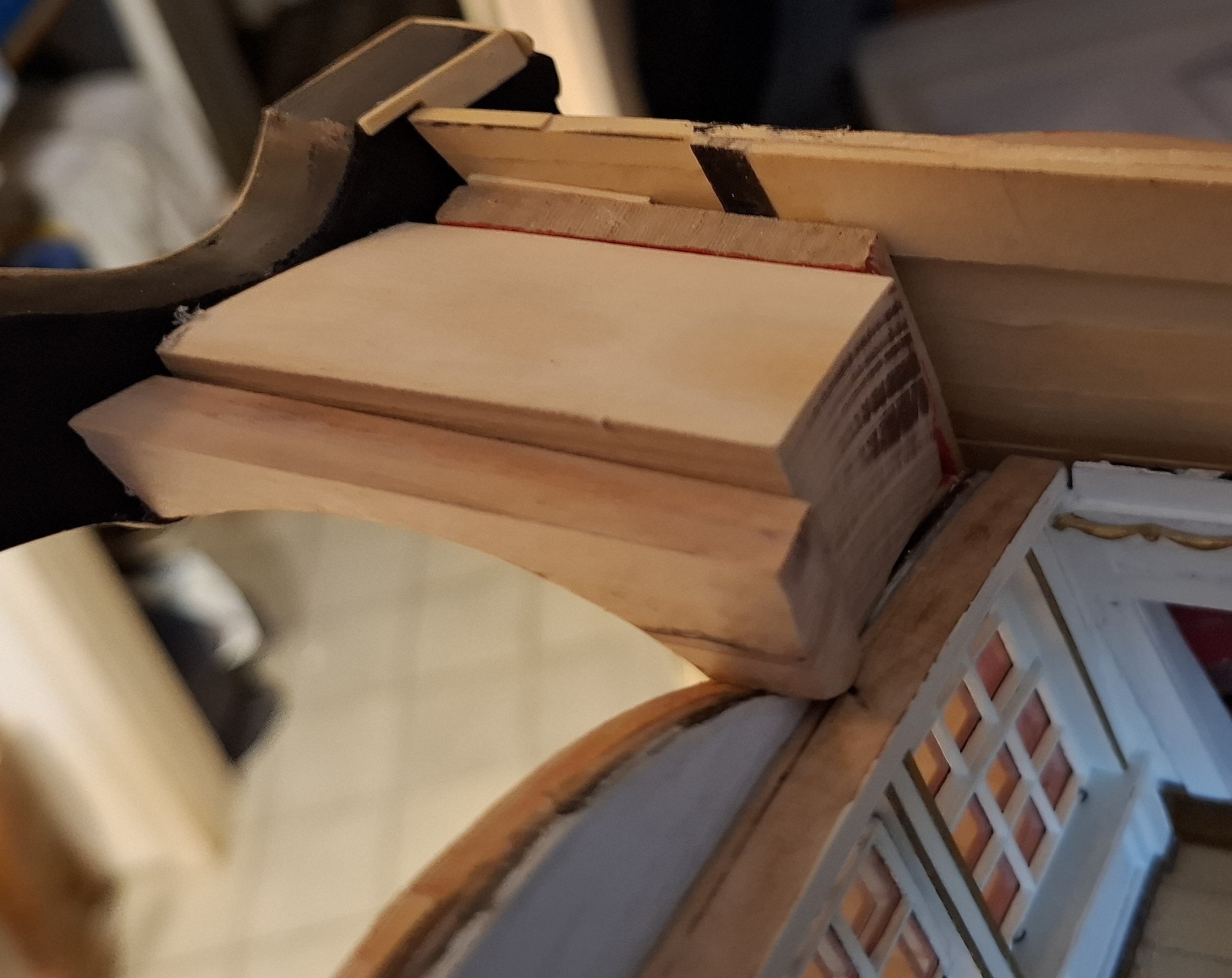
I decided not to make the canopy out of knees, support ribs and planks because of the complex shapes, but instead, as the construction will no longer be visible from above, I also chose to carve the vaults out of solid wood and insert them as a block.
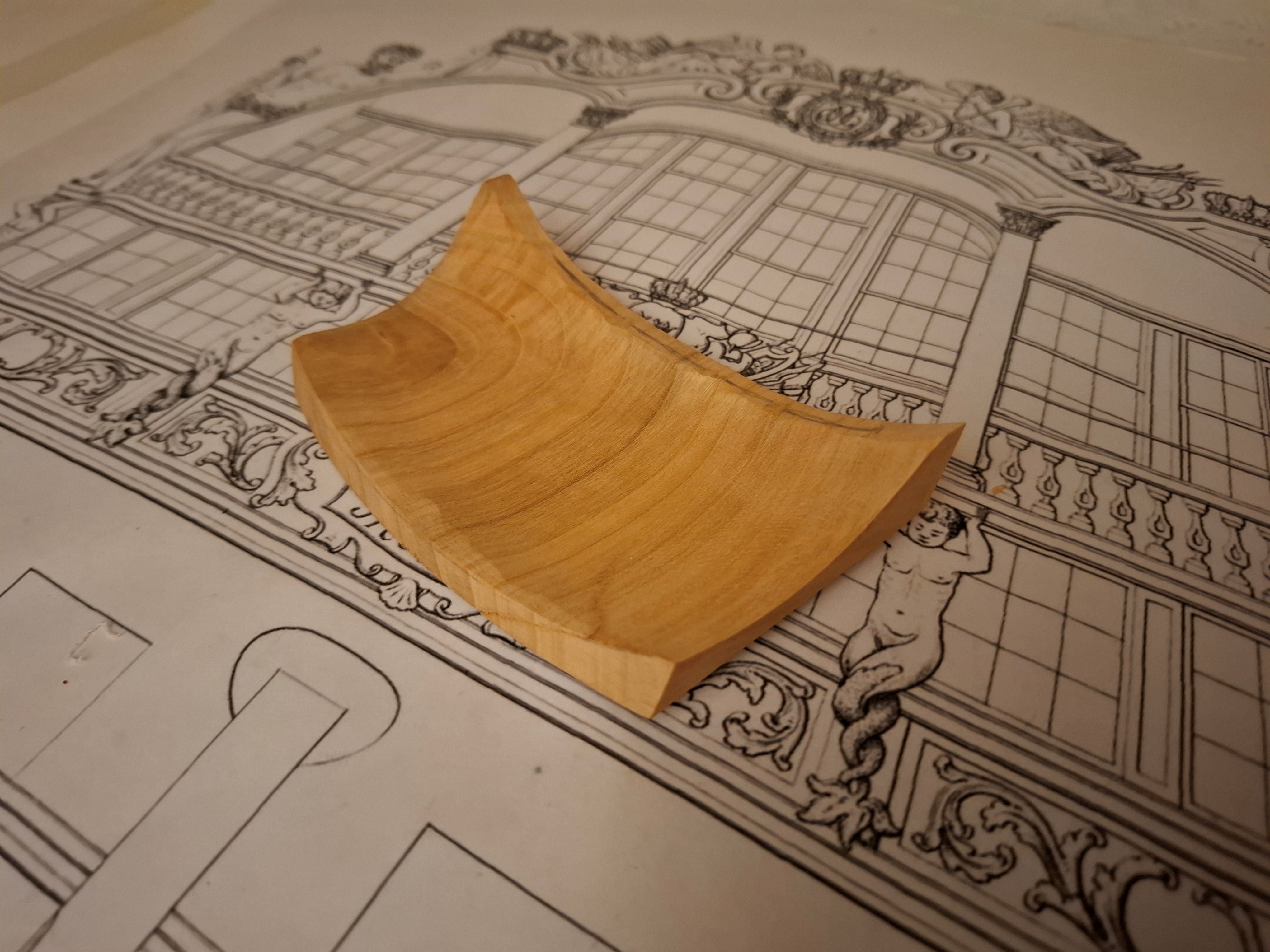
Let's start again with my paper templates to find the shape:
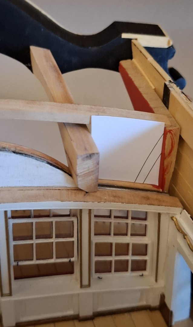
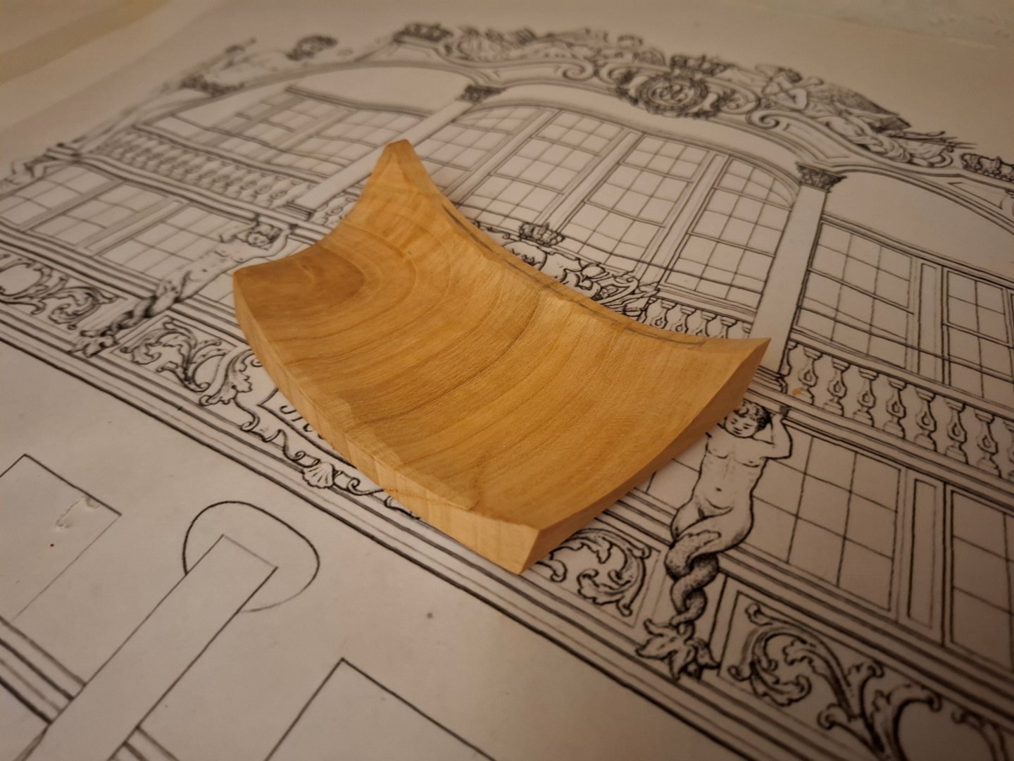
then the wooden blocks were cut to size, the vaults worked out and fitted:

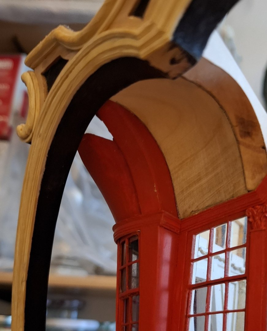

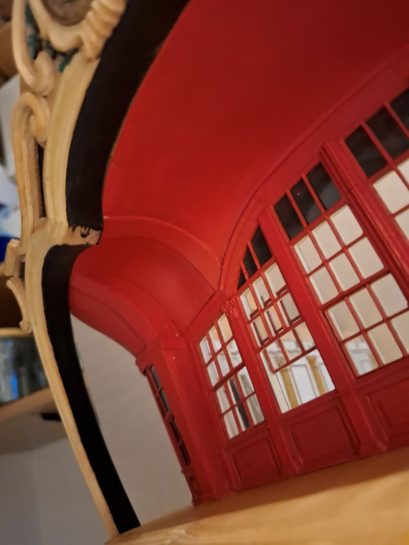
Here you can see the centre vault:
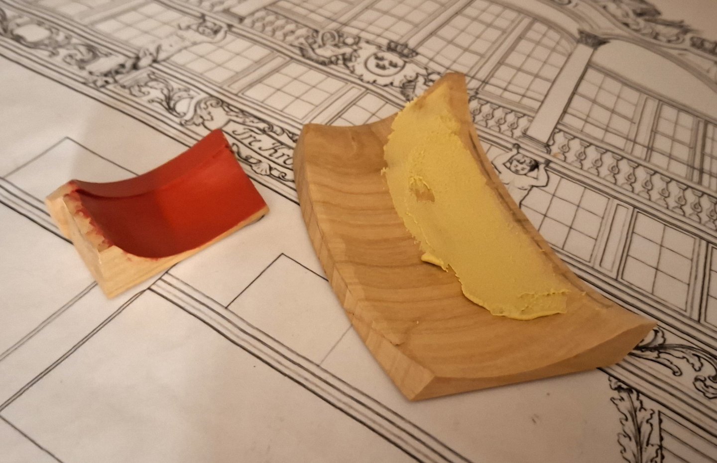
The inside is puttyled and sanded before painting so that the surface can be smoothed out nicely and the unavoidable dentswich appear, when carving out the curvatures can be levelled out.
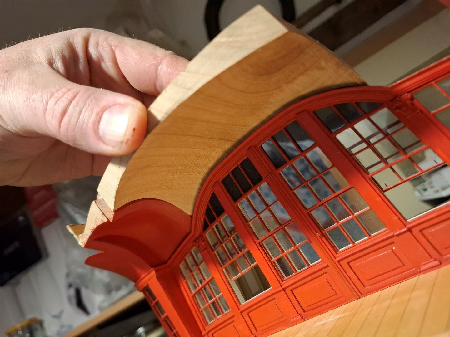
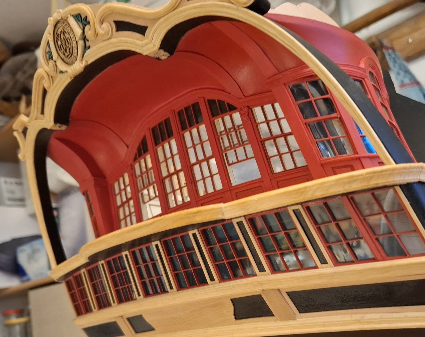
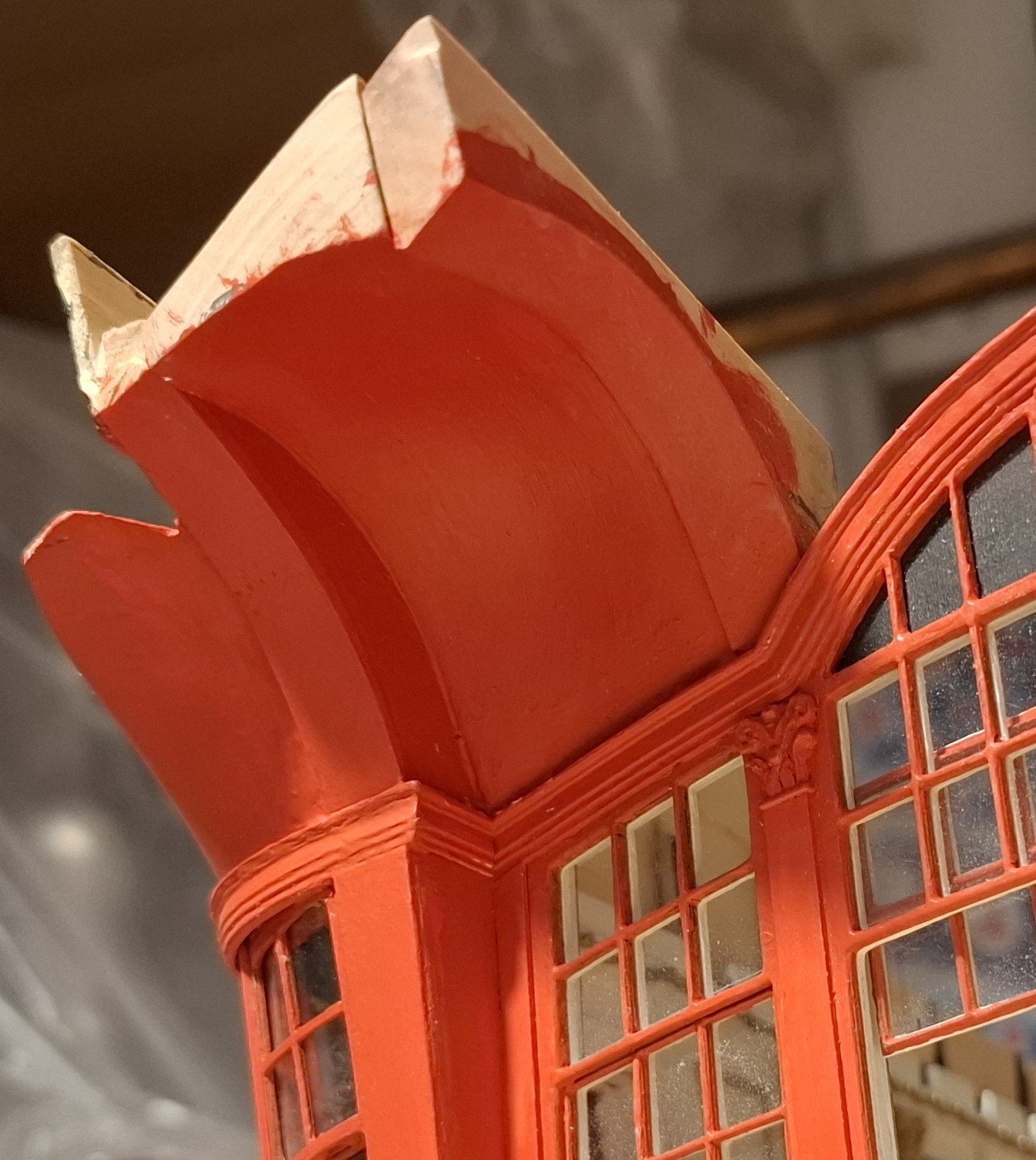
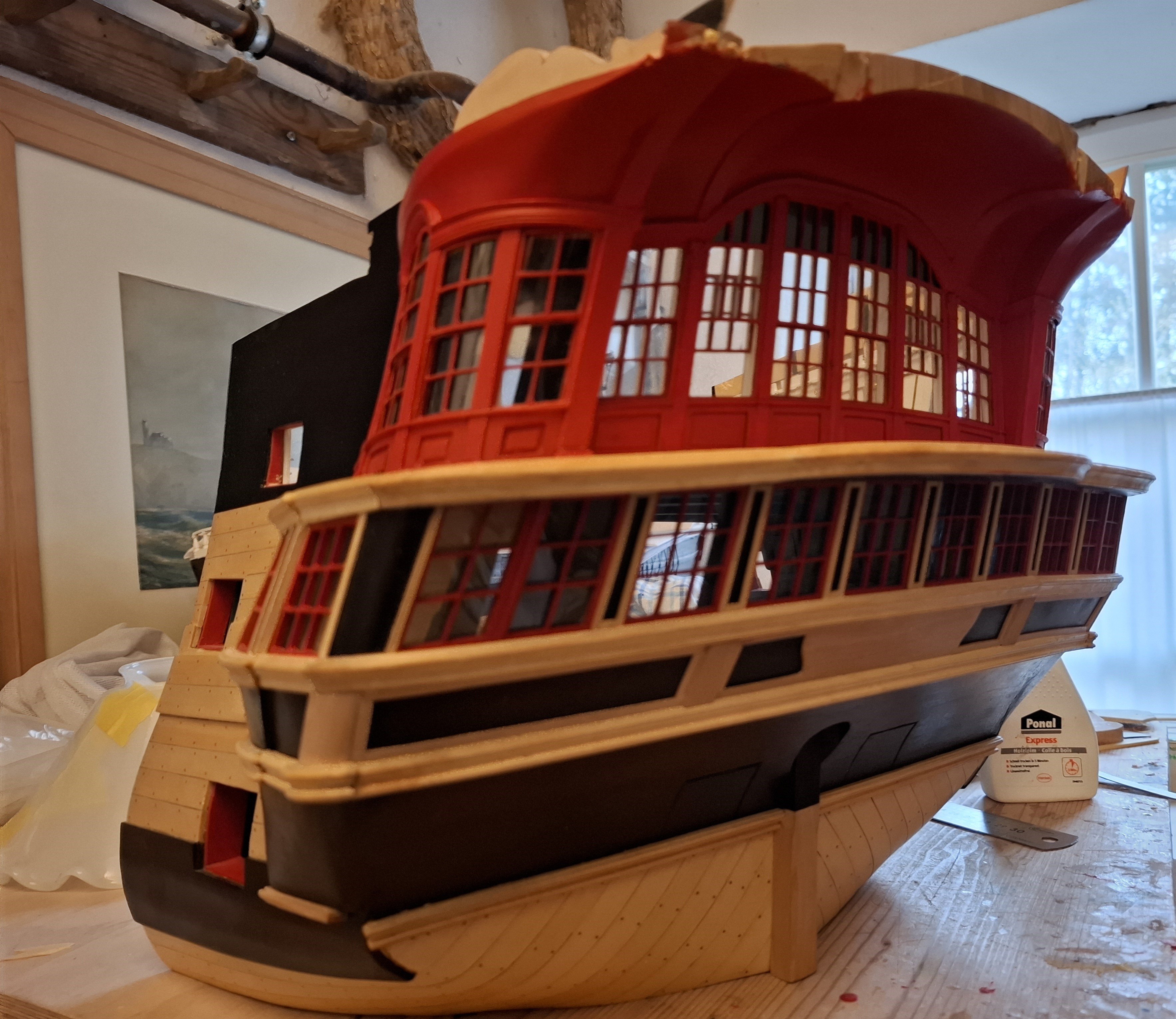
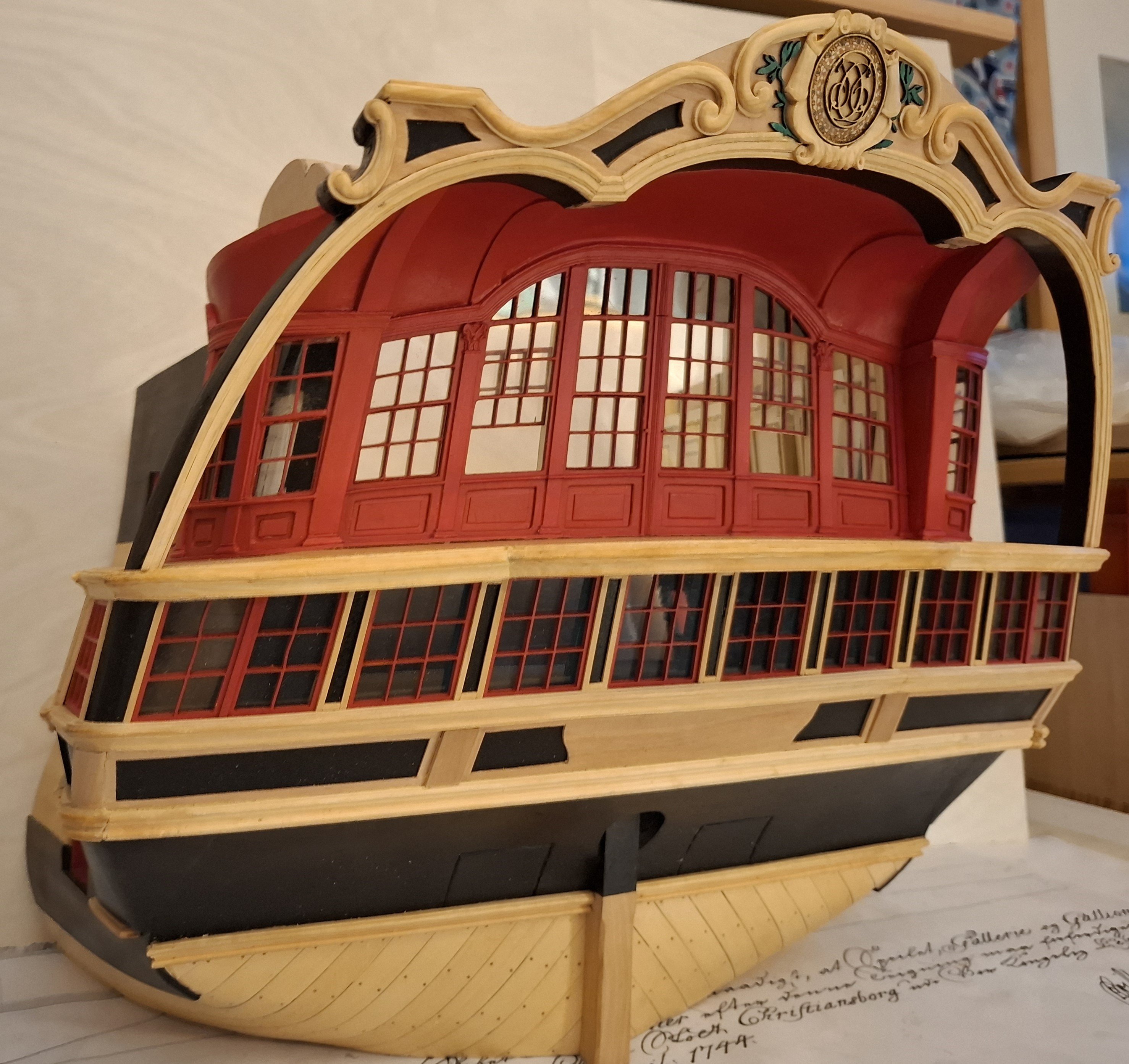
...and finally everything is fitted to the model.

...then the transom could finally be fitted.
Finally, here are some pictures of the result:


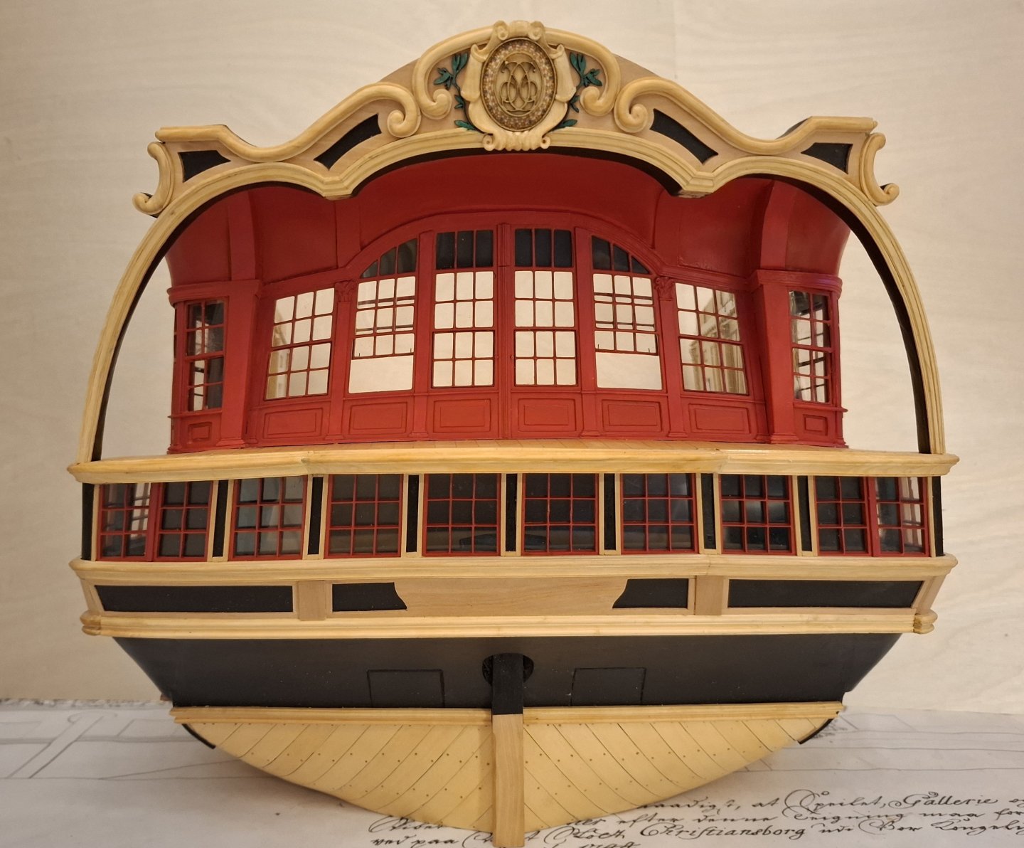
Best regards,
Matthias- vossiewulf, Dziadeczek, Javelin and 19 others
-
12
-
 10
10


HMS Cumberland 1774 by Jack H - 1:36 &1:48 - POF - kit development for True Image Models
in - Build logs for subjects built 1751 - 1800
Posted
That looks promising Jack. Looking forward to see more progress.
Matthias