Dr PR
-
Posts
2,456 -
Joined
-
Last visited
Content Type
Profiles
Forums
Gallery
Events
Everything posted by Dr PR
-
 That's only because I didn't show you a close-up! It is mostly going according to plan, but I had a problem on the port bow. I broke the sheer strake with too much pressure trying to get it to conform to the curvature of the hull. I glued it in place anyway, but it had a bit of an upward bow between bulkheads 1 and 3. That threw off the following planking, and I ended up with a "smile" between a couple of strakes. I cut a filler piece and glued it in place and now the strakes run fair. However, the taper was a bit off and now I am having to cut the port strakes a bit narrow between frames 5 and 1 to make up the difference. It won't show after the hull is sanded and painted. I have also had problems with plank thickness. I am checking plank width carefully and beveling the high side of each plank to fit snugly against the strake above it. But some of the planks are too narrow at the end, as if they were pulled out of a thickness sander too early causing the end to be too thin. I only discovered this after gluing a plank into place and then realizing that the plank that butted against the thin end was quite a bit thicker. Again, I cut a filler piece and glued it in place. Then after sanding the hull is smooth at that joint. Now I check the thickness as well as the width. I am using a 1 in 3 planking scheme. The planking butt joints are at bulkheads 5, 10 and 15, repeating every third strake.
- 476 replies
-
- 4
-

-
- minesweeper
- Cape
- (and 1 more)
-
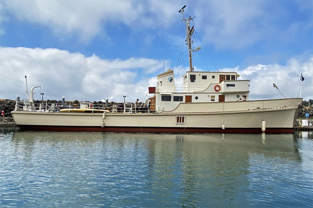
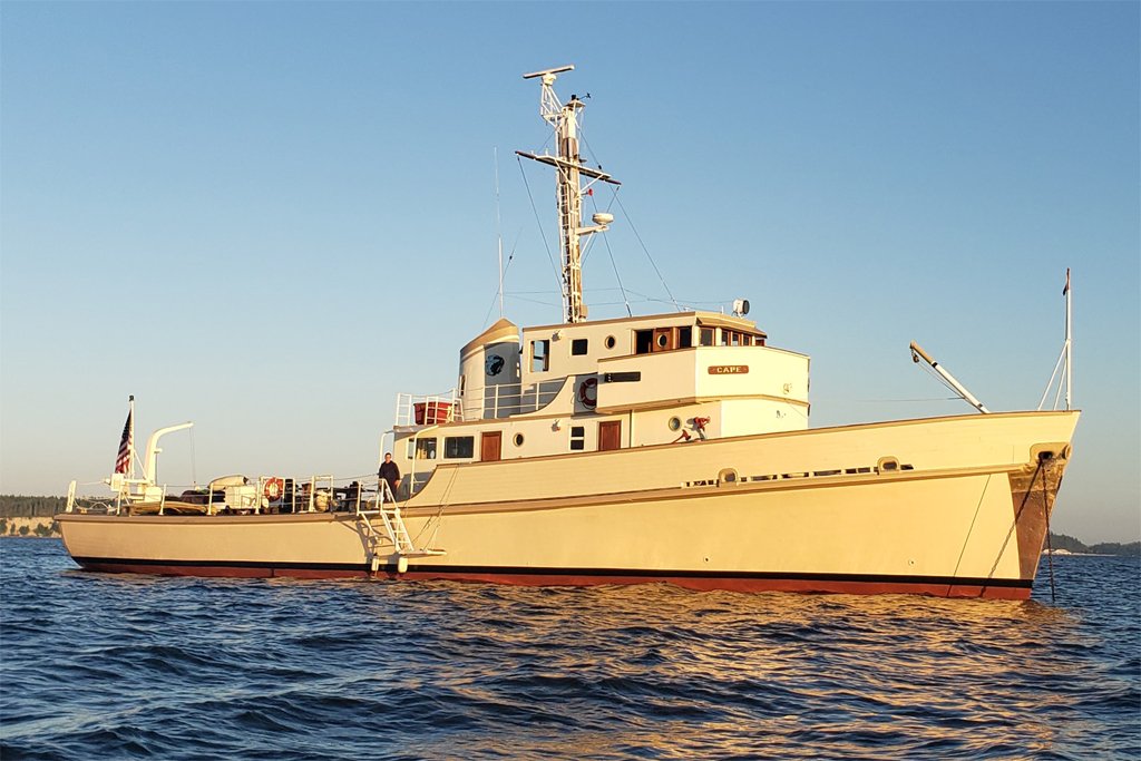
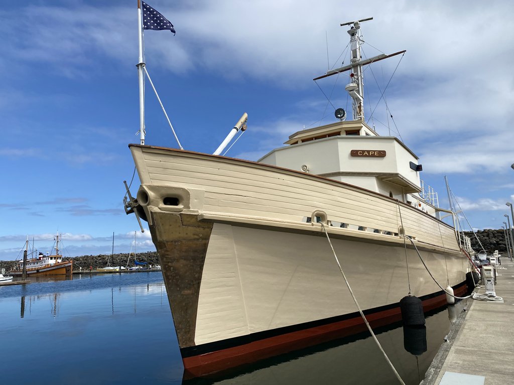
I have been in contact with Mr. Cox and he has provided some photos of the present day Cape. She looks pretty spiffy in her Bristol Beige color scheme. The ship was launched on 5 April 1958 at the Bellingham (Washington) Shipyards Company. The vessel is over 65 years old and still going strong! Austin says the hull doesn't leak (except around the stuffing boxes when running, as is to be expected). After the Navy decommissioned the Cape it was leased in 1970 to Johns Hopkins Applied Physics Lab (APL) and converted for research. I seem to have ties to APL - after leaving the Cape I was in the Talos missile battery on the Oklahoma City. APL designed the Talos missile. The ship underwent a lot of renovations when converted for oceanographic research. The minesweeping gear was removed, and more importantly, a propeller shaft brake was installed. Austin says "I can’t imagine going from forward to reverse using a man powered lever to keep the prop from freewheeling. I wouldn’t be able to go anywhere!" Amen to that! After her oceanographic research career the Cape served as a Naval Reserve training vessel for several years. Then it was sold to an Indian Nation. It fell into disrepair and broke free of the moorings, ending up beached on a sandbar. A fellow got it from the tribe in 1992 and converted it into a yacht. He took it all the way down the Pacific Coast to Long Beach (where it was when I was aboard) in 2002 for a crew reunion. Austin bought the Cape from that owner. He runs an auto and boat repair facility, so she is in good hands now. It is great to see the old girl still looking fit! **** So what about the model? I am plugging along with the planking. 16 of the 52 planks in place. 36 to go!
- 476 replies
-
- 10
-
-
- minesweeper
- Cape
- (and 1 more)
-
Austin, Good to hear from you! The last I heard the Cape was somewhere in the Puget Sound area. Do you have any recent pictures of the vessel? What condition is it in? I suspect the other members of this forum would like to hear more about how the Cape is today and what it is doing. If you want you can send me a personal message through the forum, or you can contact me through this link: https://www.okieboat.com/Contact page.html
- 476 replies
-
- 3
-
-
- minesweeper
- Cape
- (and 1 more)
-
What was the surprise in post #46? Something to do with the mast but you didn't say what. In post #47 are you allowing for the thickness of the cap rail on the bulwarks for determining bulwark height above the deck planking. If the cap rail is also 1/16 inch thick will the height be correct above the 1/16 inch deck planks? From your photos it looks as if part 13 (the subdeck at the stern) is cocked up at a pretty sharp angle.
-
I have been using the ring light for about seven months now. I did get the lithium battery and charger. The rechargeable battery lasts MUCH longer than four AA cells! It charges with a standard cell phone charging cable from a USB jack. I have had no problems and the unit still works perfectly. I have used it for all sorts of photography - even taking it into the field for wildflower pictures.
-
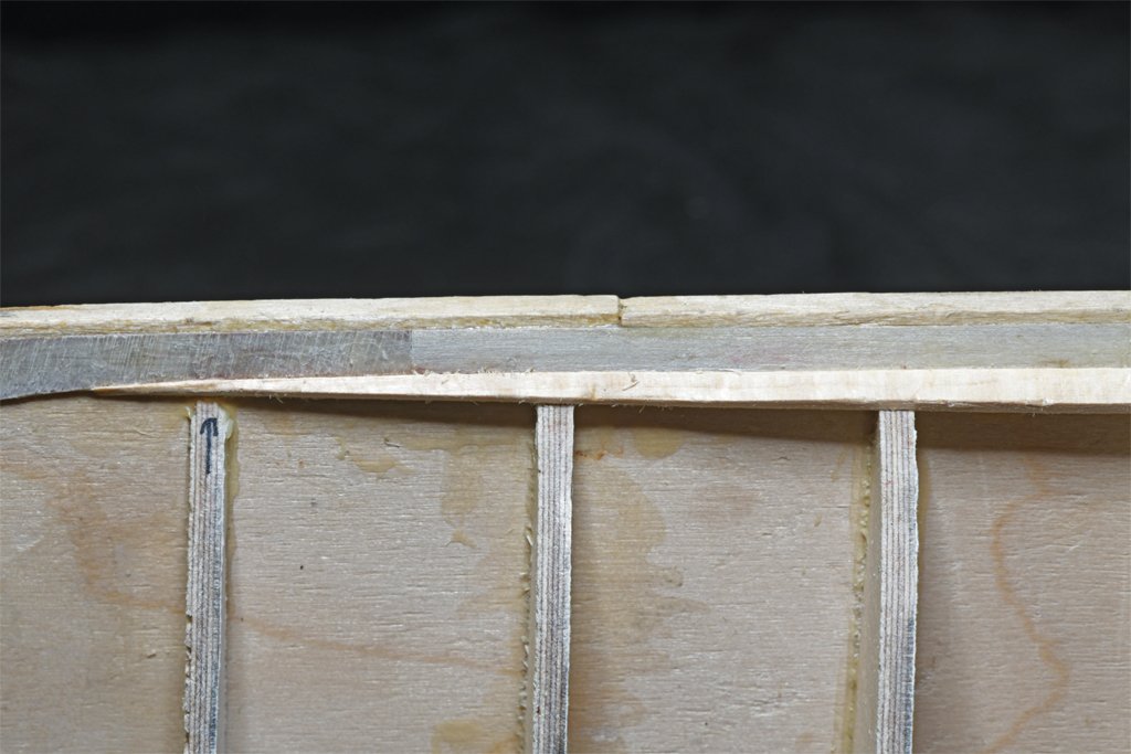
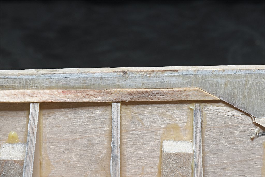
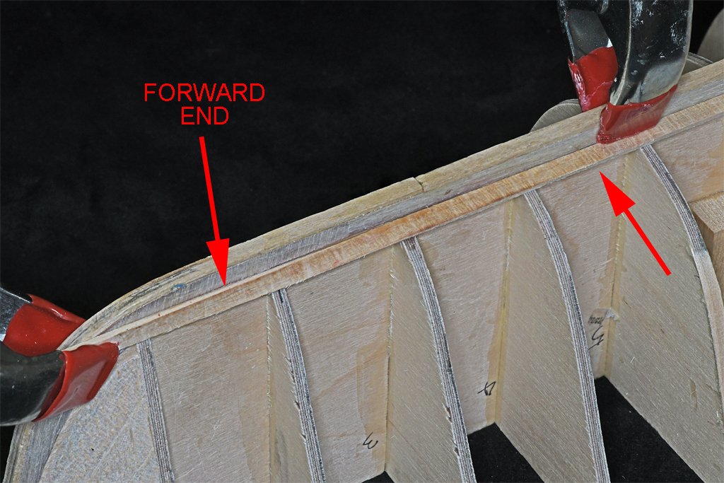
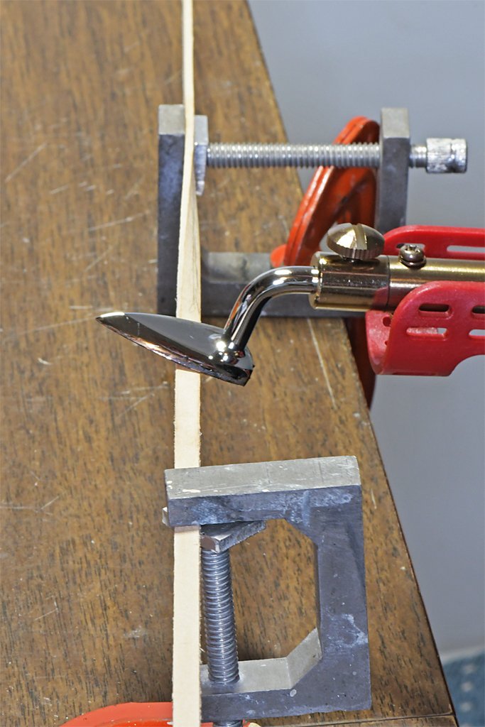
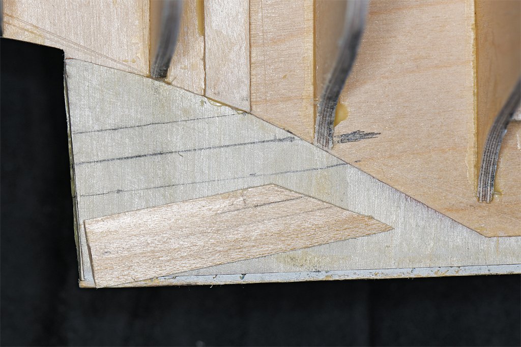
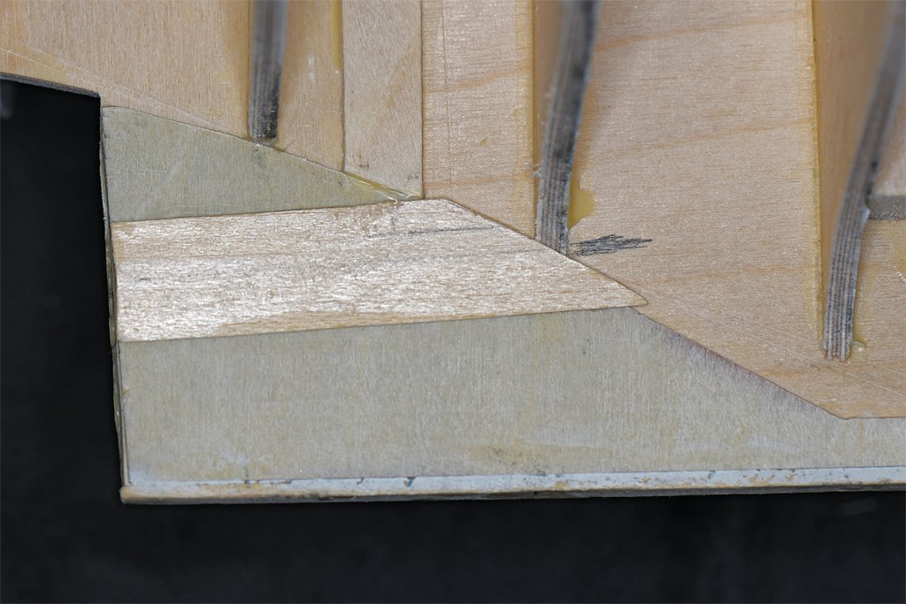
I started work on the garboard strakes today. As described above, I will make the garboard strake in two layers. The first layer is an ordinary plank to set the run of the rest of the planks. The first problem was bending the plank to the curvature of the hull. It must fit vertically at the bow and stern, but twists almost horizontal amidships. I used a single plank for this strake. It was cut it to fit into the rabbet at the stern. I clamped it into the vertical notch on the keel siding, fitting into the rabbet. Then eight bulkheads forward I used another clamp to force it to twist into the almost horizontal position against the keel siding. At the bow I did the same thing. To make the twists in the plank permanent I heated it with my quilting iron/plank bender/sail making tool. First I brushed water onto the twisted plank and let it soak in a couple of minutes. Then I heated it with the plank bender. The water turned to steam and carried the heat into the wood. I repeated this several times, allowing the wood to cool between heating sessions. It is the heat that softens the wood structure, not the water. The water just carries the heat into the wood. Water isn't necessary - I have bent many pieces using heat alone. But I think the water speeds things up a bit. After several heating/cooling sessions the plank retained the twist when the clamps were removed. Then the plank was clamped into place along the full length. Another plank was laid alongside and allowed to ride up and over the garboard strake plank at the bow. I marked a line on the garboard plank along the edge of the second plank. This showed where the straight edge of the second plank would run. Then I trimmed the garboard plank to taper to a point just forward of bulkhead #2. The blueprints do not show a clear diagram where the forward end of the garboard strake ends, but they do show the internal bulkheads in this area, and the garboard strake ends between frames 7 and 9, just a bit forward of my bulkhead #2. After the plank was trimmed I glued it into position using SIG Bond cement. I clamped it securely along the entire length. The glue sets in about 40 minutes, but doesn't fully harden until overnight. But after three or four hours it is OK to remove the clamps. Here is the hull with the starboard side garboard strake. Here are close ups of the forward and aft ends of the strake. I decided to try another method to put the twists in the port garboard plank. I clamped the end vertically. About seven inches from that I clamped the plank horizontally, putting a 90 degree twist in it. Then I alternately wetted the wood and heated it with the plank bender. This was repeated four or five times, allowing the plank to cool between heating. After the plank had cooled the last time the clamps were removed. The plank retained the twist with only a little spring back. The 90 degree twist is more than needed on the hull, so the plank fit into position properly along the port side rabbet. The forward and aft ends must be trimmed to fit and then I will glue it in place over night. The next step will be to mark the plank spacings for the other 24 planks on each side. These planks will be tapered to fit the curvature of the hull.

- 476 replies
-
- 10
-
-
- minesweeper
- Cape
- (and 1 more)
-
Are those electric plank benders worth it?
Dr PR replied to Spaceman Spiff's topic in Modeling tools and Workshop Equipment
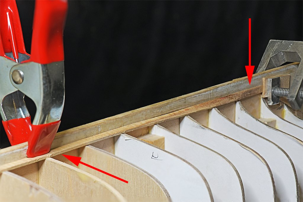
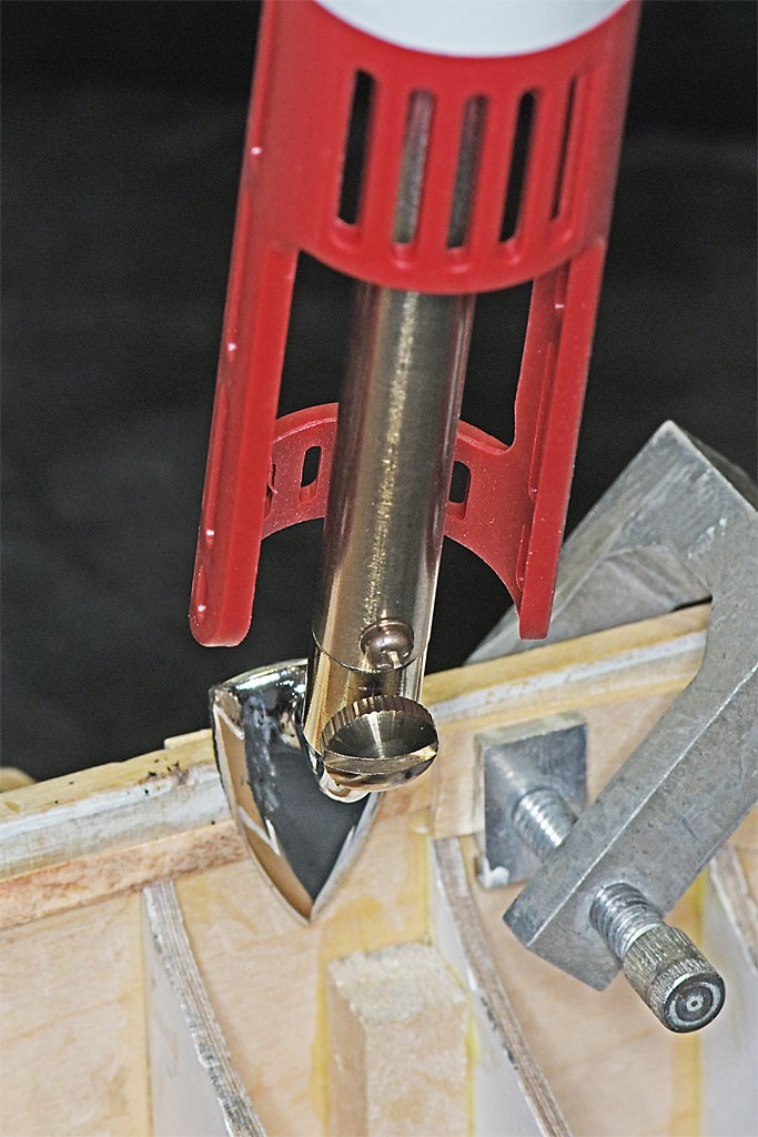
I saw this little Mini Iron II (Clover No. 9100) "quilting iron" recommended as a plank bender in another thread. It is sold as a small iron for use with quilt making. However, it is basically a small 40 Watt soldering iron with a special tip. I have used it many times now and can recommend it as an inexpensive and versatile model making tool. The picture on the left shows the tool being used to bend a plank that is already clamped in place on a hull. The photo on the right shows it being used to heat the bend into a plank that has been twisted between two clamps. In both cases brushed some water onto the surface of the plank and then heated it with the iron that was set to the highest heat setting (it has low, medium and high settings). It is the heat that sets the bend into the fibers in the wood. All the water is for it to conduct the heat into the wood. But this is not the only use for this tool. It is also useful for making sails. I used it to iron the sail material smooth - it is not nearly as bulky as a large fabric iron. I also used it to set the glue when adding tablings, linings and bolt ropes to silkspan sails. The low heat setting is safe to use with silkspan. And who knows? Maybe some day you (or someone you know) will want to make a quilt.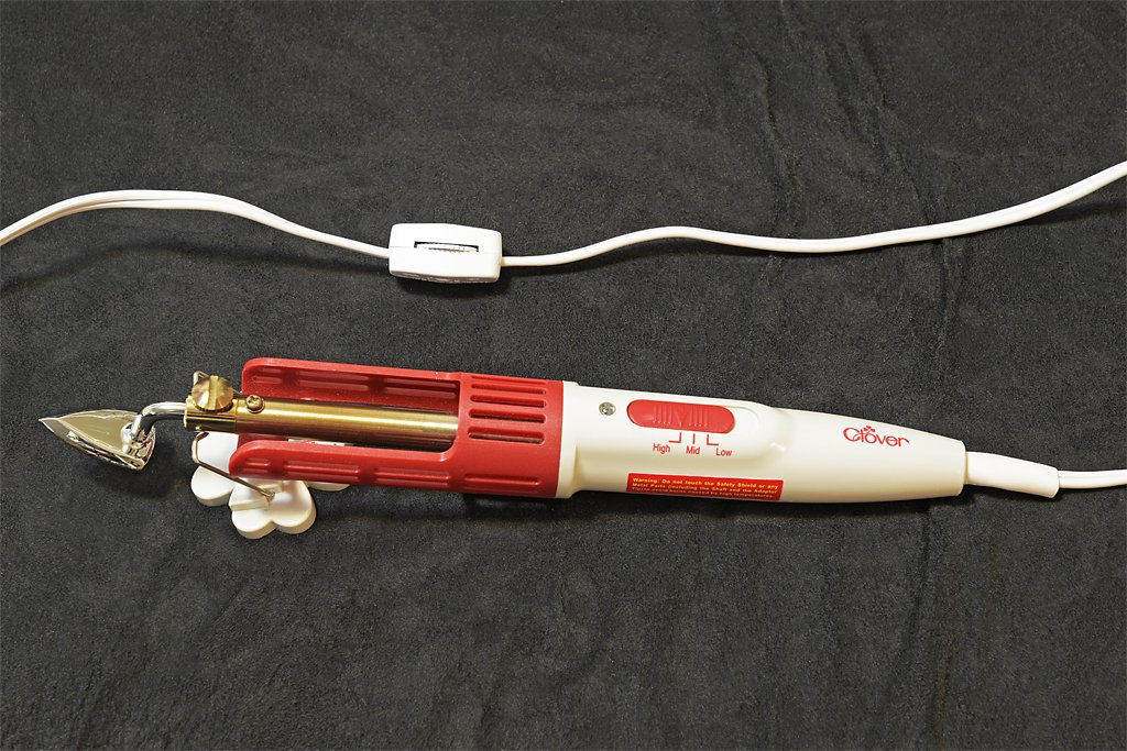

-
Dowmer and John, thanks! A nice thing about the diluted white glue (Elmer's Glue All) is it dries clear and is invisible. So it is perfect for gluing down the ends of the points. Even better, it is totally transparent when the sail is back lighted - although the glue is there it is not visible but the shadow of the points on the back side is. The combination of silkspan and white glue is very good for sails. In an earlier post I said if I couldn't erase all of an errant pencil mark I could just paint over it with the same paint I used to color the sails and the mark wouldn't be visible. While this is true, the additional paint shows up as a dark splotch when the sail is back lighted! Not perfect! But most models are viewed with light from the viewer's direction so it really isn't noticeable. But is is better to not have errant pencil marks! Another thing I have noticed is that some modelers use multiple layers of silkspan on each sail. I am not sure why they do this. One reason for using silkspan is that it is very thin, close to scale thickness for sail material. Perhaps for larger scales (1:35 or 1:25) a thicker material would be better, but there are several thicknesses of silkspan, I used the thinnest for this 1:48 scale model, and it is about 0.001 inch (0.0254 mm) thick, or about 0.05 inch (1.27 mm) at 1:1 scale. Light weight modern cotton sail cloths are 0.012 to 0.025 inch (0.3 to 0.65 mm) thick (1:1 scale). So the thinnest silkspan is about a medium weight scale sail cloth at 1:48.
-
After fiddling with it a bit, removing wood at some places and adding at others, the run of the sheer planks fairs nicely. I have seen several otherwise nice models that had very noticeable "warped" deck edges or bulwarks when viewed end on, and I really wanted to avoid that here. I think it is worth the extra effort. Two down and fifty more to go!
- 476 replies
-
- 11
-
-
- minesweeper
- Cape
- (and 1 more)
-
Sort of reminds me of the spaghetti I had for dinner.
-
John, Thanks! I will need to iron the sails again before installing them. The wrinkles iron out nicely. I have built only one model previously with sails - a 1969 model kit (Billings?) of the Santa Maria with paper sails. Only three sails with none of the details. For this model I wanted to see how much detail would be needed. The sails and their rigging are almost as much work as the rest of the ship. I still have a long way to go before it is finished! If I ever build another model with sails I think I will cut the silkspan into 2 scale foot strips and glue them together instead of drawing in the seams with pencil. When doubled like that the seams look more realistic when backlighted than the parallel pencil marks.
-
Help with depicting extra line on bitts
Dr PR replied to usedtosail's topic in Masting, rigging and sails
Someone will have to explain to me how the lines would work if they were wrapped around the horizontal part of the bitts. Think about it. even if you had only one loop around the bitts the entire length of line would have to be pulled through around it. This would have to be repeated for every turn around the horizontal piece. This would take forever, and could never be used at sea! It looks pretty silly to me. Has anyone seen a period model or photos of a period model (or a modern replica ship) that had lines tied off like this? Has anyone read a period rigging book that described belaying lines like this? Is there any reference for this??? The first photo in Lees Masting and Rigging (after page 37) of a model of the Breda shows two small lines wrapped around the horizontal beam of bitts at the base of the main mast. It looks like one of them is a fall from a runner block. Or it might just be a small line used to secure a larger line to the bitts. Some of the lines could be belayed to eye bolts in the deck behind the bits. But most of the lines that belay at the base of a mast are falls from tackle, often from blocks belayed to eye bolts in the deck at the base of the mast. But when they are belayed to eye bolts they are distributed around the base of the mast so it is easy to distinguish each line - they aren't bunched together as in the Speedy model photos. Until someone can provide a period reference for this practice I will remain skeptical. -
Here are the sails with reef points installed. Fore topsail. Fore sail (fore gaff sail). Main sail (main gaff sail). The ends of the reef points are fastened to the sail with drops of white glue. Some will need repositioning to make them "hang" more realistically. Now I need to add blocks for the sheets and clewlines to the topsail and ties to attach the gaff sails to the mast hoops. The topsail will be tied to the topsail yard and the gaff sails will be laced to the gaffs. Then I should be ready to start rigging the sails to the masts.


-
John, It will be better to see it finished! I thought I had done a pretty good job fairing the bulkheads to get a smooth planking run from bow to stern. However, I can see now after placing the sheer strake that there are a couple of bulkheads that are not quite right. They cause "bumps" or high points in the run of the planking. These are obvious if you look down the line of the planking from bow to stern. This isn't my first rodeo, so it isn't totally unexpected at the start of the planking. One place is on the port side at bulkhead 15, and the other is on the starboard at bulkhead 11 and 12. In both cases the discrepancy is about half a plank width. I could just sand these places to remove the high spot, but I really don't want to make the planking that thin - I might sand a hole in the planking. It won't be a problem to remove material from the edges of the bulkheads - except where I just glued the sheer strakes in place. I will have to cut between the planks and the bulkheads very carefully. I have some very narrow kerf saw blades for my hobby knife that should do the job. But I am not looking forward to doing it!
- 476 replies
-
- 3
-
-
- minesweeper
- Cape
- (and 1 more)
-
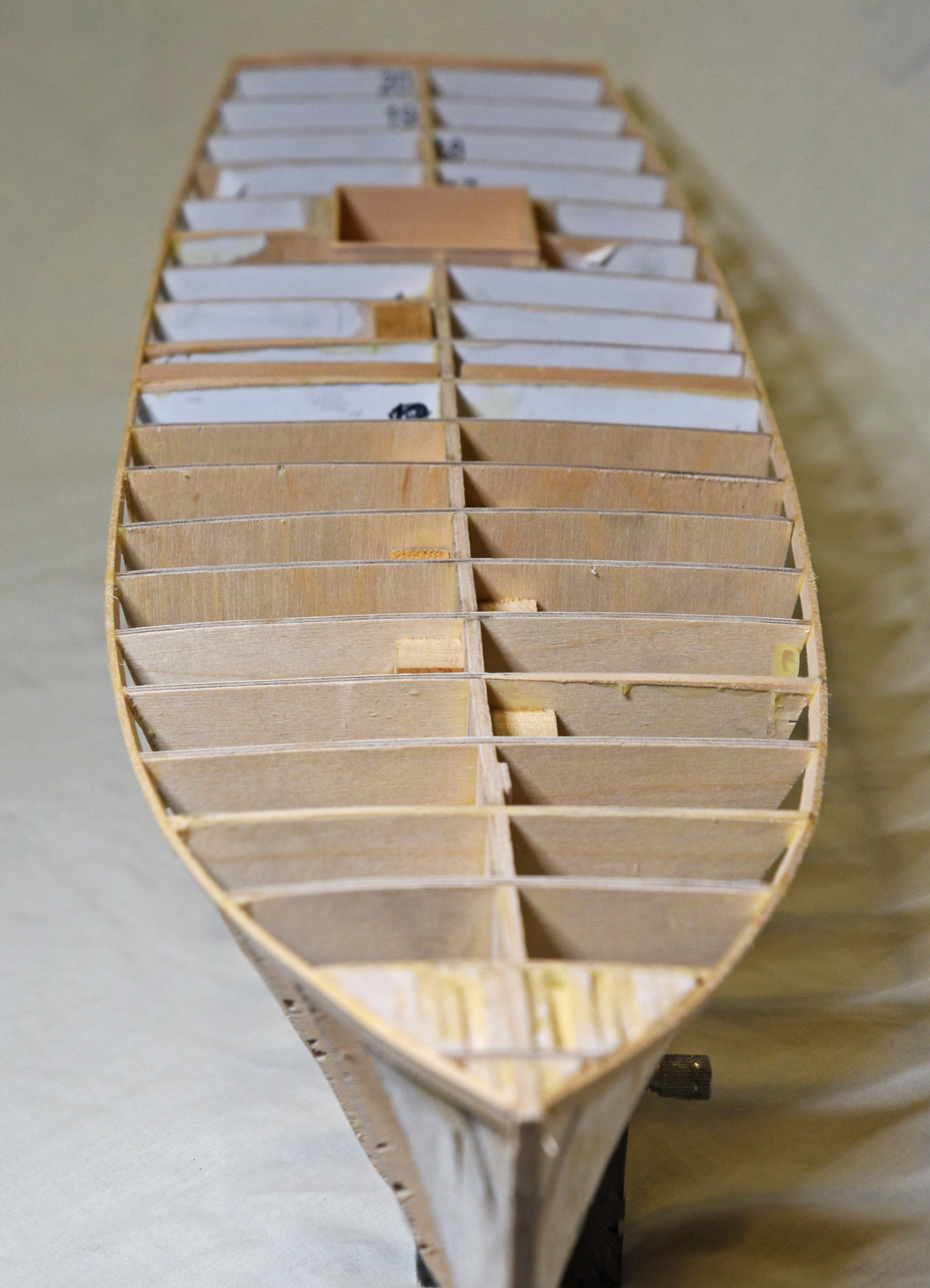
I have started planking the hull. I started with the port sheer strake. First I glued it to the filler wood between the first two bulkheads. After the glue set I proceed aft, gluing the plank to a few bulkheads at a time. I had to work slowly near the bow where the hull flairs outward at the top, getting the right twist in the plank to make it fit flush against the bulkhead. But after the first five or six bulkheads the plank fit snugly against the remaining bulkheads. After the sheer strakes are in place I will install the garboard strakes. Then will come the long process of tapering the remaining planks and installing them. This will take some time.
- 476 replies
-
- 12
-
-
- minesweeper
- Cape
- (and 1 more)
-
Up to this point I have thought the most tedious part of this build was rigging the cannons. I certainly do not want to build a model with several dozen cannons on deck that need to be fully rigged! But today I found something even more tedious than rigging cannons. What you are looking at is 80 reef points (or just called "points"). 13 for the topsail, 25 for the fore sail, and 36 for the main sail - plus 6 extras. The fore course would have 17 more, but I plan to rig that sail furled to the spar and I don't want the extra bulk in the sail. It took several boring hours to tie all of these! The points will be 1 inch (25.4 mm) long on each side of the sail. I experimented and found that the overhand knots will consume 1/8 inch (3.2 mm) of the point thread each. I cut 80 pieces 2.5 inches (63.5 mm) long. Then I tied an overhand knot in each, positioned 1 inch from one end. I placed a crop of white glue (diluted 1:1 with water) on the knots so they won't come untied. After that I dipped the long end of the thread in the white glue to stiffen it. This end will have to pass through a hole in the sail in the reef band. After passing the long end through the hole in the sail I will need to tie another overhand knot in each point, snugging it up as close to the sail material as possible. Then the long ends will be trimmed to 1 inch long. I suspect this will be even more boring and tedious that creating the 80 individual points. I am also working on my MSI model, and have it built to the point of planking the hull. That will be a slow process, installing one plank at a time and waiting for the glue to set. While waiting for that I will be doing work on the schooner model to finish rigging the sails.

-
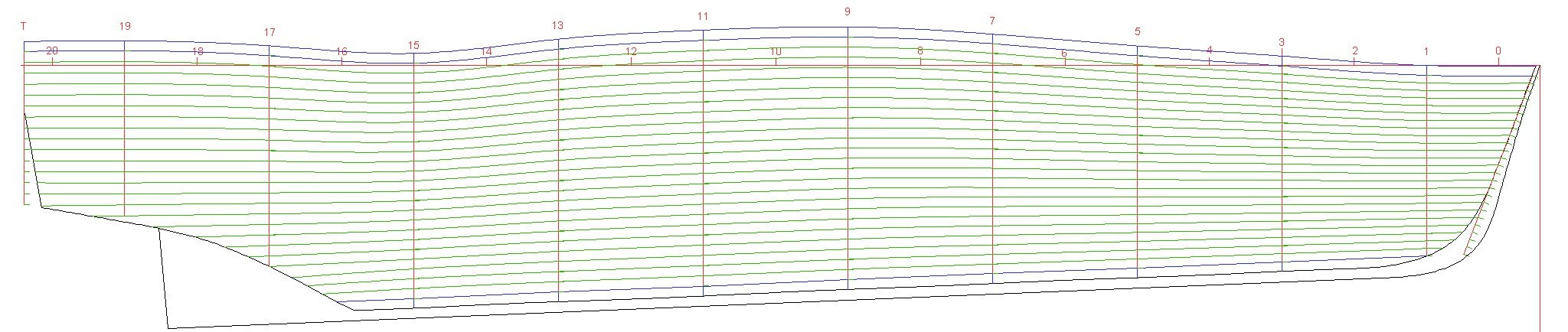
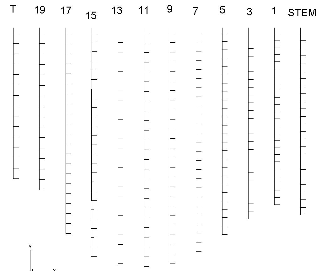
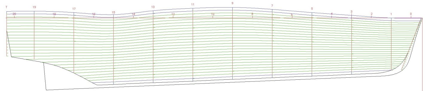
I cut the rabbets deeper at the stern and shaped the fairing around the propeller shaft. The fairing is still a bit over sized. I will sand and file it to the final shape after the stern frame for the prop shaft and rudder has been attached. I have been thinking about plank widths, planking fans and such. Since I have the basic hull patterns in CAD I decided to measure the distances from keel to deck on the bulkheads and divide the distance by the number of planks to determine the plank widths at every other bulkhead. Then I can print the patterns and transfer them to the edges of the bulkheads. Because there are only shallow curves to the hull (no bulbous bow or curved tuck at the stern) the planks will have very gentle tapers. It is easy to bend a plank around the deck edges with curvature for the sheer. After studying how the planks fit on the hull I decided to make the top strake and the garboard (bottom) strakes without taper. Then the planks between these will be tapered. I ordered 3/16 inch (4.8 mm) basswood strips for the hull planking. However when I measured them none are close to 3/16 (0.1875) inch. The widest was 0.185 inch and the narrowest 0.176 inch. I measured 65 strips and the average width was 0.1797 inch (the median was 0.180 inch). So I have to plan the planking pattern around 0.180 inch (4.57 mm) planks. Actually, this isn't a bad thing because the scale plank width is a bit smaller than 3/16 inch. Here is the hull planking expansion drawing relative to the rabbet for the garboard plank. The planks won't actually be wavy because this is the pattern of the curved hull sides laid flat. Thr different lenghs along the bulkhead edges plus the number of planks at each bulkhead cause the curvature. From this I prepared the bulkhead plank spacing scales. I will use these to place marks on the edges of the bulkheads to guide plank tapering.
- 476 replies
-
- 5
-

-
-
- minesweeper
- Cape
- (and 1 more)
-
Instructions for using shellac on furniture caution against getting alcohol or water on the finished surface. Water can cause it to turn a lighter color. However, they say that you can apply alcohol with cotton sponges and reflow the shellac to restore the finish. It is a good bet that the alcohol in the paint softened or dissolved the shellac.
-
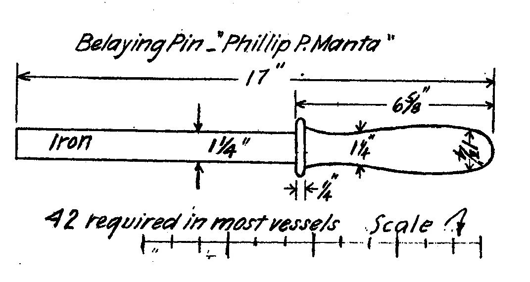
Banyan, In the drawing I posted for a wooden pin after 1800, the diameter of the lower part of the pin was 1/16 of the full length of the pin (1). So, if the lower part of the pin was equal in diameter to the rope diameter, and the rope diameter was 1 inch, the pin would be 16 times as long as the diameter of the rope. 16 x 1" = 16" I agree with Wefalck that zu Mondfeld covers such a broad range of dates and nationalities it really must be considered a summary and not a detailed compilation. I think its greatest value is to show just how different similar things were throughout time and geography. While studying schooner rigging I came across several authoritative works telling how to build and rig these vessels, each with its rules or formulae for calculating dimensions. No two sets of these "rules" were the same, but the results were similar. There were distinct differences among nationalities, and within each nationality the construction and rigging differed for warships, merchantmen, privateer, slavers and pirates. And each Captain or owner had a preferred way to do things. I doubt that there ever were any two ships that were exactly the same! I would bet there really was no "standard" for belaying pins. Each locality probably had it's own "right" way to make them, and even individual ships may have had a "better" way. So take all these rules with a grain of salt.
-
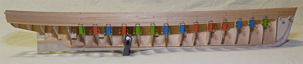
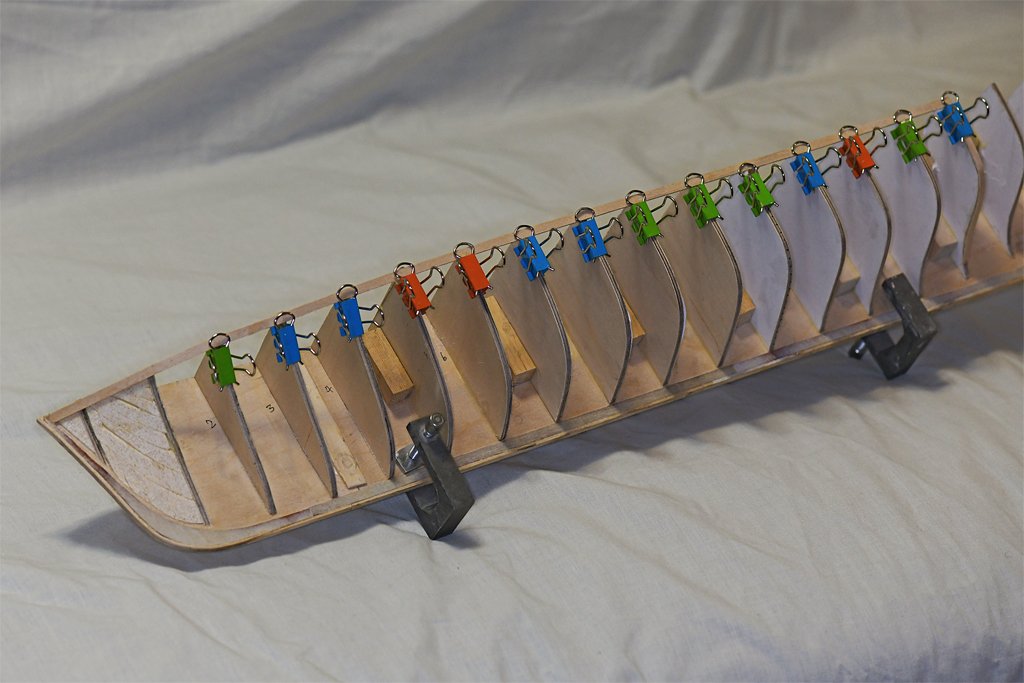
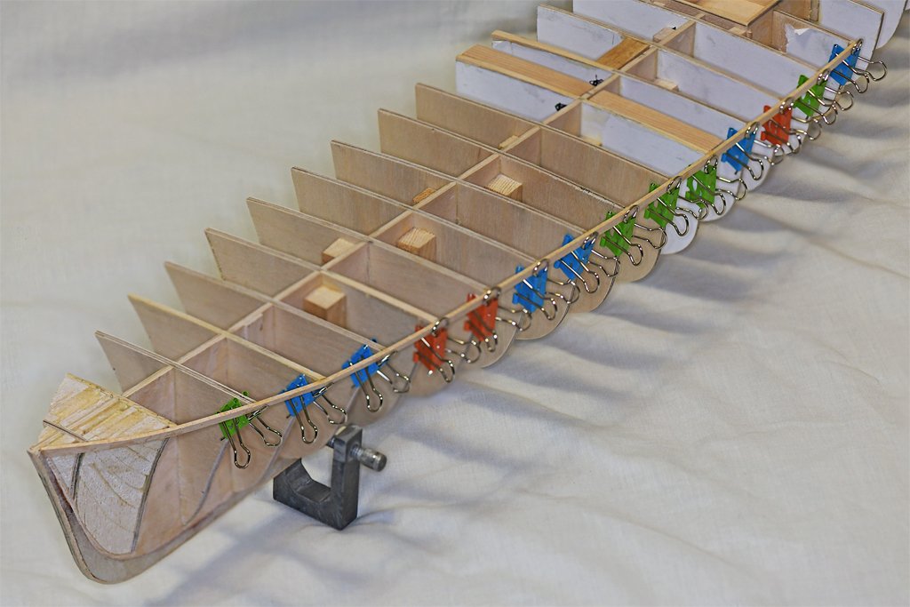
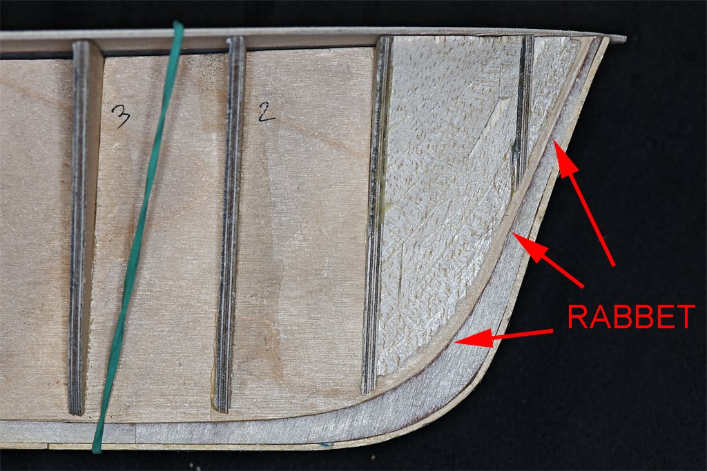
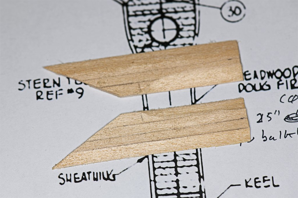
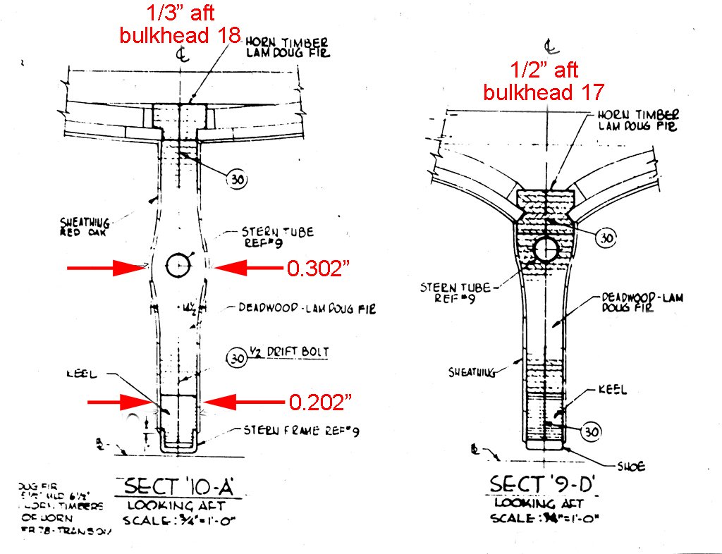
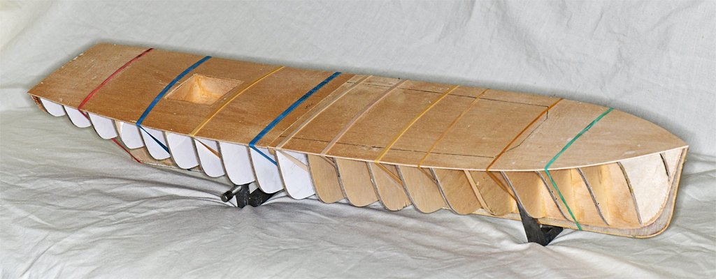
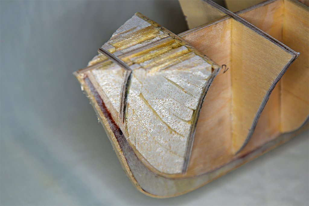
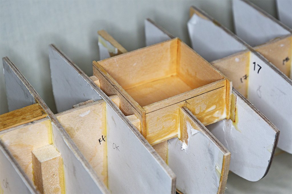
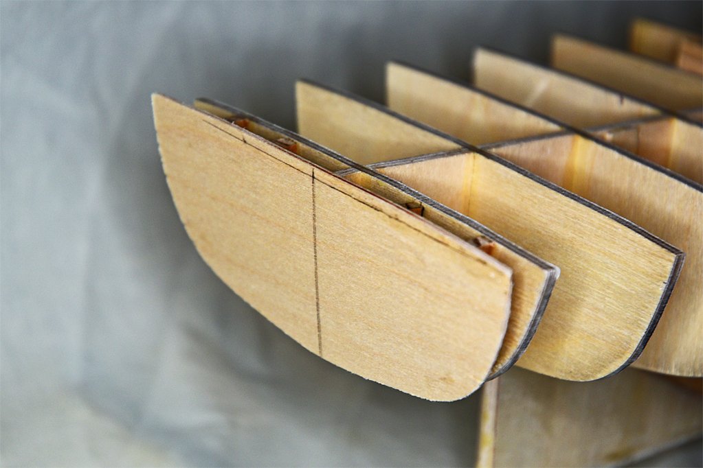
I have been plodding along on the model when I can find time. I cut out the 1/16 inch (1.6 mm) plywood subdeck. It is in two sections. The aft piece has been fitted around the well for the magtail reel. I am using rubber bands to pre-form the plywood pieces to the sheer and camber of the hull. I'm not sure this will help much but it is worth a try. The subdeck hasn't been glued to the bulkheads. I will do that after the hull planking is complete. This gives me access to the interior of the hull during planking, and afterwards for coating the interior with clear epoxy to glue everything together. The subdeck pieces are cut wider than the finished size to allow the plywood to be shaped to fit over the top of the hull planking all around. The plank sheer pieces around the deck edges will be shaped to fit to the edges of the sub deck. A guard piece will fit over the edge of the plywood and part of the top planking strake. Next up was cutting the rabbet for the planking at the bow. The 1/32 inch (0.79 mm) thick keel siding creates a rabbet suitable for the garboard strake. But at the bow the rabbet should be 1/16 inch deep for the planking, so I had to carve out a shallow cut behind the edge of the keel siding. Carving the stem will be interesting. In theory (according to the blueprints) the stem will be shaped to continue the angle of the hull planking, creating a relatively sharp prow. Along the front edge of the stem will be a thin brass "stem band" 0.050 inch ((1.27 mm) wide. I say "in theory" because as I place hull planks on the bow the angle changes constantly from the keel up to the deck level, and I am not sure the resulting width of the forward edge of the stem will be a constant width. To be continued ... Another thing that had to be done before I start planking the hull is to create the fairing around the propeller shaft on the keel/deadwood at the stern. The keel is 0.202 inch (5.1 mm) thick, but there is a swelling or fairing around the propeller shaft that should be 0.302 inches (7.7 mm) wide as shown in the drawing above. The vertical height of this fairing is about 0.54 inches (13.8 mm). I cut two pieces of 1/16 inch basswood to be glued onto the keel/deadwood to fashion the fairing. These were pre-shaped to create the approximate curvature of the fairings. The propeller shaft exits the hull with a slight downward angle. After the glue hardens I will finish shaping the pieces with round files and sandpaper. A bit of putty might be needed here. The hull planking will have to be fitted around these fairings and that could be interesting. I will also probably need to carve the rabbet a bit deeper here in front of the keel siding pieces.
- 476 replies
-
- 9
-
-
- minesweeper
- Cape
- (and 1 more)
-
I would do the soldering and and shaping or polishing first, then blacken the finished piece. Birchwood Casey Brass Black does blacken solder at least as good, if not better, than it blackens brass. Note - I use tin/lead solder and I suspect it is the tin that is blackened, I don't know about silver solder or some of the newer lead free solders. Be certain the metal is clean of oils and solder flux.
-
Here are some things I found for belaying pin dimensions. Chapelle's American Fishing Schooners had this illustration: Mondfeld gives has a diagram of belaying pin proportions and gives a general description in Historic Ship Models: "Generally speaking, the lower diameter of a belaying pin was never less than the diameter of the rope which was to be belayed. As only one size of belaying pin was kept on board, its diameter was that of the thickest rope to be belayed." Starting with the largest rope diameter to be belayed, and using that as the lower diameter of the pin, you can calculate the overall pin length from these diagrams. For example, if the largest rope was 1 inch diameter and the pin was wooden from after 1800, the pin length would be 1 x 16 = 16 inches. Mondfeld also says the British used metal pins that tapered at both ends in the late 1700s. These were force fit into the holes in pin rails.
-
bdg2, Thanks for that link. There are not many minesweepers on display to the public. From the look of the photo they have a long way to go to restore the ship. Some minesweepers were converted for private yachts, and all of the minesweep gear was removed. Finding replacement MSO sweep gear, winches and such will not be easy!
- 476 replies
-
- 2
-
-
- minesweeper
- Cape
- (and 1 more)
-
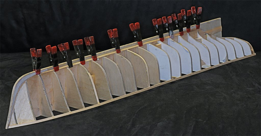
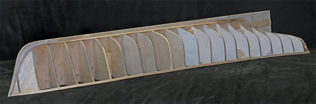
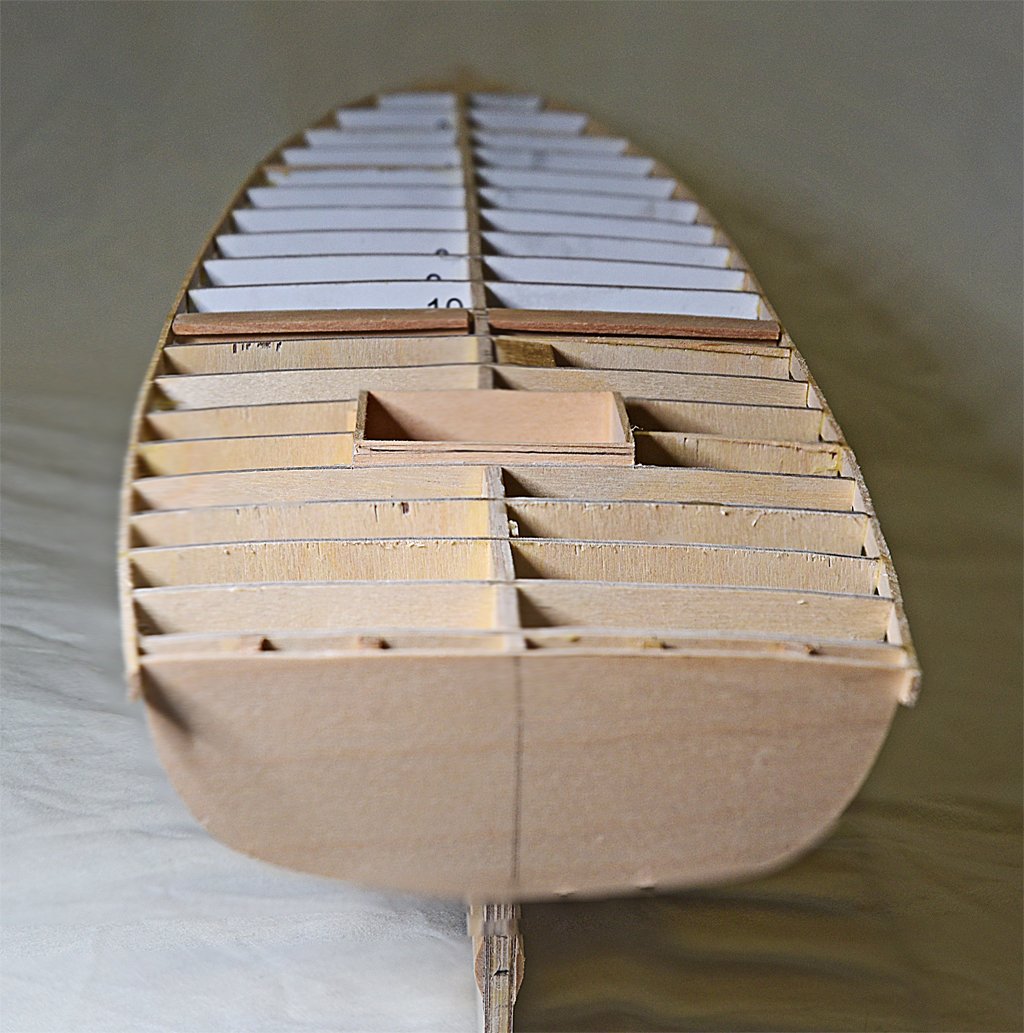
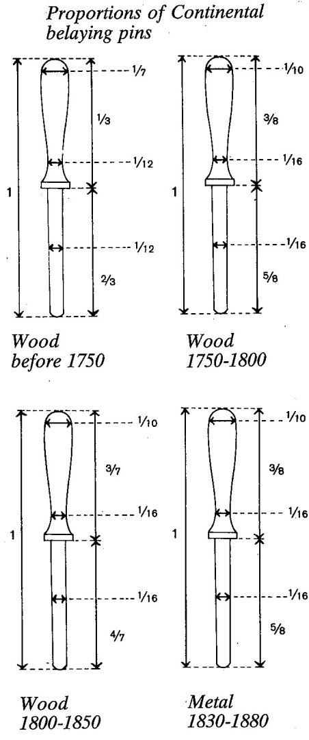
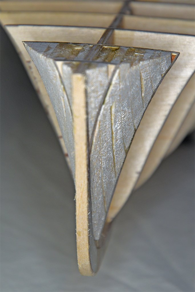
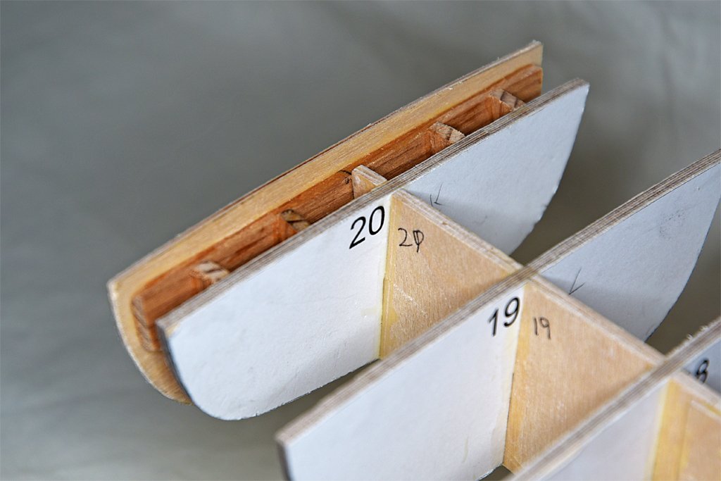
More progress. I carved, filed and sanded the bow filler and it now looks respectable. The SIG Bond cement is much harder than the balsa when it dries. The glue seams are quite apparent. Actually, I think it must be harder than basswood, because when sanding the edges of the SIG plywood it seems the wood is removed first, leaving a bit of a high point at the glue seams. I kept working this until a batten lay flat against the balsa surface in any orientation I put it. The next project was the well for the magtail reel (the magnetic minesweep gear). The well sides will rise above the 1/16 inch (1.6 mm) plywood sub deck, and then be sanded down flush with the top of the sub deck. The 1/16 inch deck planking will lay over the top edges of the well sides (at the level of the black pencil line). The fore/aft length of the well opening should theoretically be 2.12 inches (53.8 mm) and it came out to 2.15 (54.6 mm). I can live with that. I had some metal clamps that were exactly 2 inches (50.8 mm) wide and square that I used to make the width of the well very precise to 2.0 inches. When I took this picture the SIG Bond glue hadn't dried yet. Then I installed the transom. The 1/16 inch (1.6 mm) thick transom piece is oversized all around. It was glued to the spacer pieces to get the correct angle at the stern. Later it will be faired to the curvature of the hull and deck. Then the hull should be ready for planking.
- 476 replies
-
- 9
-
-
- minesweeper
- Cape
- (and 1 more)