
HOLIDAY DONATION DRIVE - SUPPORT MSW - DO YOUR PART TO KEEP THIS GREAT FORUM GOING! (89 donations so far out of 49,000 members - C'mon guys!)
×


Dr PR
-
Posts
2,444 -
Joined
-
Last visited
Content Type
Profiles
Forums
Gallery
Events
Everything posted by Dr PR
-
 Very nice work!
 -
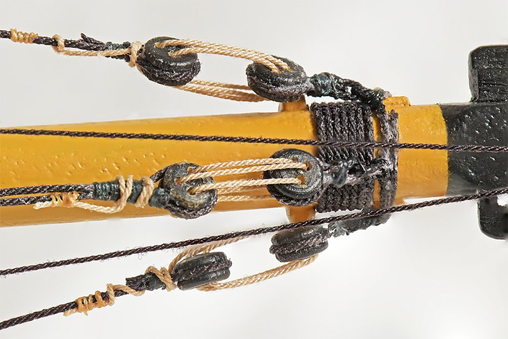
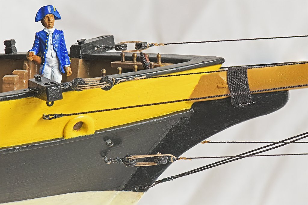
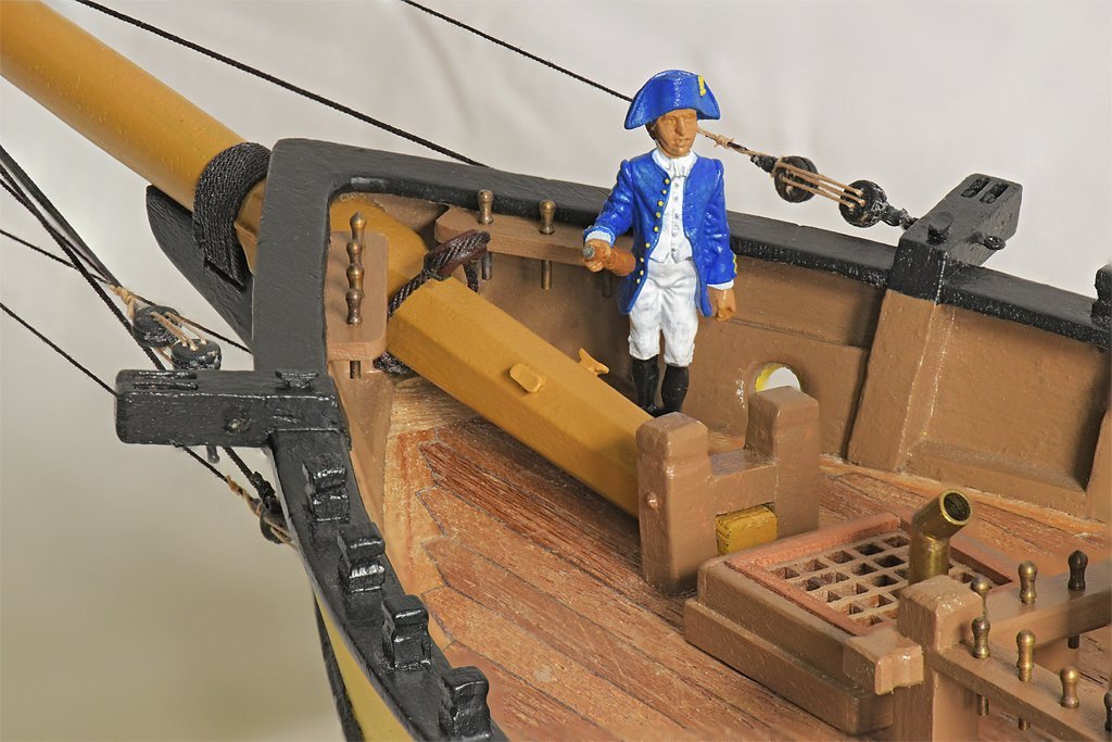
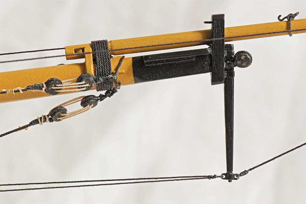
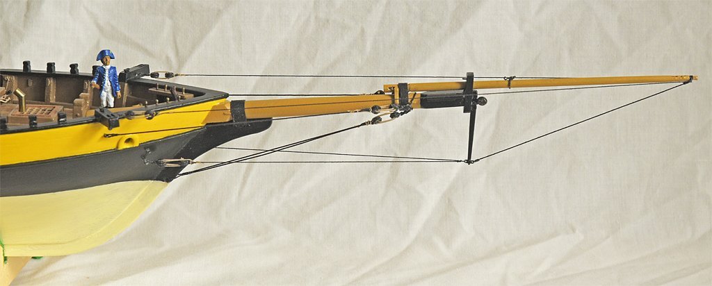
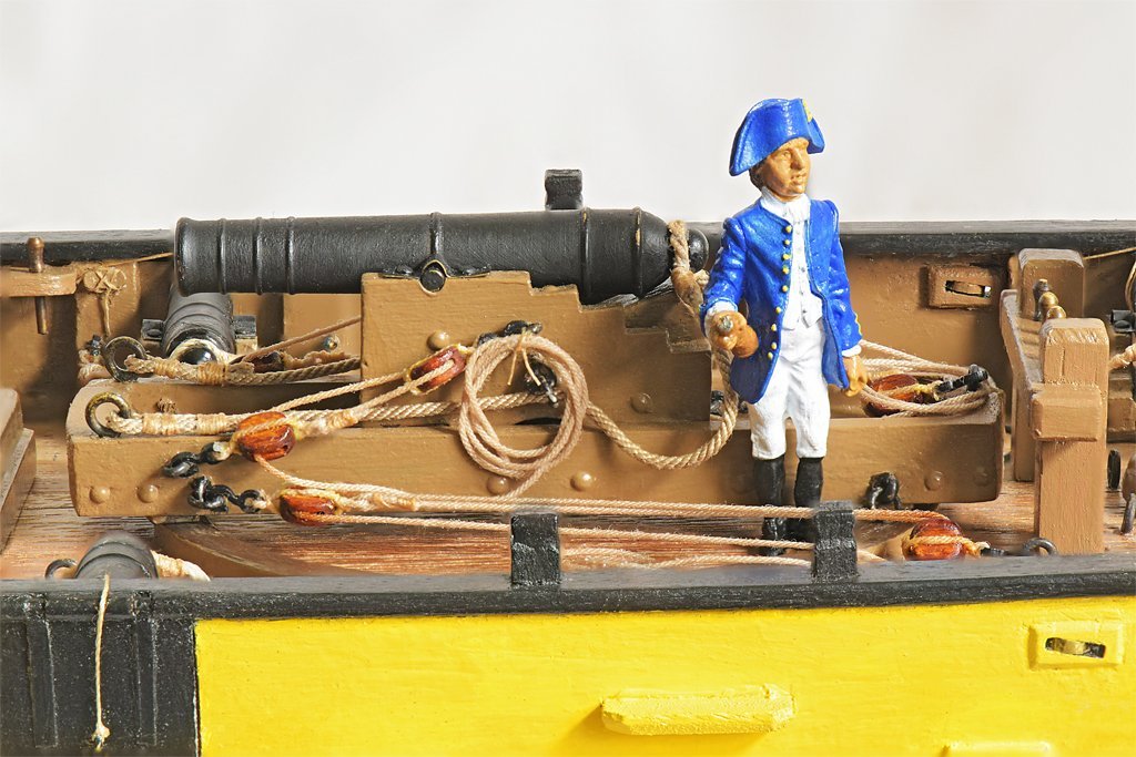
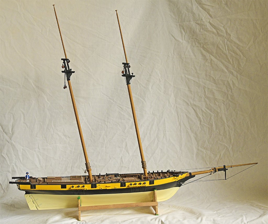
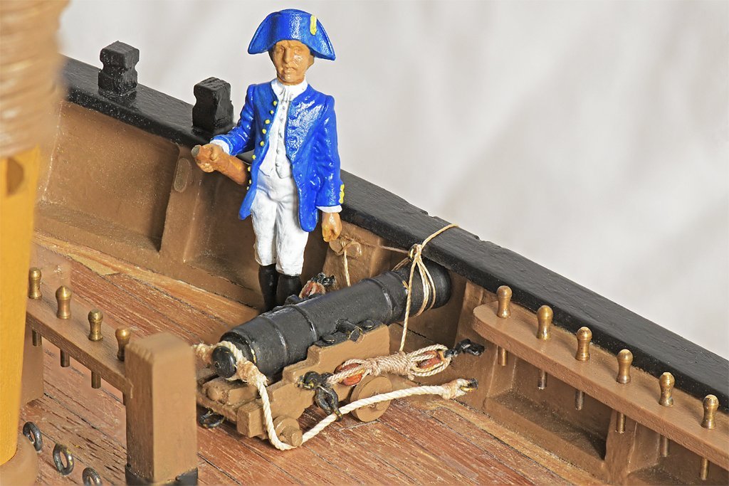
I have finished the bowsprit standing rigging. There are probably as many variations on this as there were ships, but the configuration I am using was found on some smaller vessels. You can see the octagonal bowsprit housing in this photo, with the heel stepped between the two bits. I added two cleats for belaying miscellaneous lines. I had to wait until the bowsprit was installed to add these because they wouldn't pass through the hole in the bow. The open heart for the forestay also could be installed only as the bowsprit was being put into place. I found this Amati cast metal figure on line, and use it to show the scale. However, it is a peculiar size - 35 mm high. At 1:48 this makes the fellow about 5.6 feet tall (1,7 meters) with hat, or about 5.2 feet without the hat. So it is really about a 1:55 scale figure, assuming the fellow is 5' 6" tall (1,7 meters). Why would anyone make a 1:55 scale figure?? Either people were shorter 200 years ago, or perhaps this is a midshipman! Perhaps it is Napoleon's cousin? Anyway, it does give a general idea of the size of things. I would like to find an actual 1:48 scale (O scale) figure 35-38 mm without hat or 37-40 mm with hat. The gammmoning fastens the bowsprit to the knee on the stem or head of the ship. The jib boom guys attach to the catheads with 3.5 mm deadeyes. Some vessels used hearts and others used thimbles. The lanyards are half the diameter of the guys or shrouds and are belayed by taking a few turns around the guy and securing with seizing. The bowsprit shrouds (port and starboard) are secured to eyebolts below the catheads. The eyebolts below the hawse openings will secure the jib stay (stbd) and preventer (port). Below these the martingale backstays (P & S) attach to eyebolts with deadeyes and lanyards. The bobstay is doubled, passing through a hole in the stem and secured with seizing. The bowsprit head is the belaying point for several lines. The martingale (dolphin striker) is attached to the bowsprit cap. At the bottom end is a metal fitting where the two martingale backstays are secured on the aft side (left in the photo). On the fore side the aft end of the martingale stay is belayed. The other end has an eye looped around the end of the jib boom. You can see the traveler on the jib boom and the sheave in the base of the boom for the jib boom outhaul (not rigged). The deadeye on the starboard side of the front of the bowsprit cap is for the foretop stay. The flying jib stay (traveler outhaul) tackle will attach on the port side of the bowsprit cap. The most complex part of the rigging is the bobstay collar. This has three deadeyes attached to it. The port and starboard deadeyes are for the bowsprit shrouds. The center deadeye is for the bobstay. I made the collar a bit too loose. It is supposed to fit tight in front of the three thumb cleats attached to the bowsprit, but you can see that it actually rides over the two thumb cleats on the sides of the bowsprit, and is hooked in front of the top one only. Here are a couple more pictures to show scale, with the 12 pounder pivot gun on the left and a 6 pounder carriage gun on the right. And finally, a photo of the entire ship as it stands today. The masts have not been installed permanently. I am still working on some of the rigging that will be easier to attach with the masts off the ship.
-
The books say to just lash the free end to the nearest loop of the gammoning with seizing. That is what I did on my model.
-
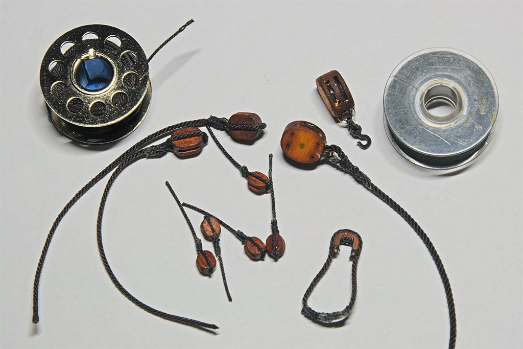
Free at last, free at last!!! Taxes are done and now I can get back to important things like ship modeling! Only some small progress to report. I am adding rigging to the mast and bowsprit that will be easier to install before the assemblies are added to the hull permanently. Lots of blocks and such. I have actually installed the bowsprit onto the ship, and am working on the stays. One thing I needed to do was make tools for setting the spacing between deadeyes. The vessel has 5 mm deadeyes on the channels and 3.5 mm deadeyes in the tops and in some rigging on the bowsprit. Here are photos of the tools. I saw this in another post on the forum and it is an easy and simple way to achieve constant spacing. I selected brass wire a bit smaller diameter than the holes in the deadeyes, twisted two pieces together and soldered them. Then I shaped and cut them to space the deadeyes the desired amount - 0.75" (19 mm) for the 5 mm deadeyes, and 0.5" (13 mm) for the 3.5 mm parts. You can't get much simpler than that! Here are photos of the tool in use. These deadeyes are on the bobstay. The bobstay deadeye is part of a collar with deadeyes on either side for the bowsprit shrouds. The tool was used to position the left (in the photo) deadeye while the bobstay was secured around it with seizing. Then the tool was removed and the lashings added to draw the stay taut. The free end of the lashing was looped around the stay and the end secured with a lashing. With this the rigging of the bowsprit has commenced! Note: I wondered if the lanyards should be dark brown like the stays, or lighter tan like the running rigging. The general opinion on the forum is that they are the lighter color. I consulted several of the standard references and did not find an answer. However, lashings must be fairly limber to be able to pull them through the deadeyes, hearts, thimbles and such (Lever says to grease the lanyards good so they can be pulled very tight), so they are considered running rigging. The ropes of the running rigging are tarred as they are made, but no extra tar has to be added before use. The running rigging wears out and is occasionally replaced, so it is typically light in color. In contrast, the more permanent standing rigging periodically was retarred for protection from the elements and was usually darker.
-
shipman, My thoughts exactly! My first ship was a 112 foot inshore minesweeper USS Cape MSI-2. It bounced around like a cork in heavy seas. We walked (or crawled) on the deck, bulkheads, passage walls, whatever, hanging on for dear life all the time. The open bridge submerged occasionally when we dove into waves, and we had water sloshing over our feet for the entire watch. 112 feet (34 meters) is FAR too small to be out on the ocean!! The Cyclone class destroyers were only 45 meters (147 feet)! Still too small in my opinion!!!
-
Valeriy, You are right about the photos. During a ship's service a lot of modifications can be made, but most are not documented. If we have plans they are usually for the initial design. A few years after there may be a lot of modifications. In some cases it may never be clear exactly when changes were made. In an early photo the modifications are not there, and a photo from a few years later shows them. However, in some cases we can be more certain. While working on my OK City model I found two photos made a day apart, with an obvious change in the later photo. It is rare to be able to pin down a date with that accuracy!
-
Valeriy, I saw a part of a movie titled "Admiral" on YouTube. It was a battle between a Russian vessel and a larger German ship. The Russian ship looked a lot like the destroyer model you are making. It was a very well made movie sequence. Have you seen it? Phil
-
The bands around mast tops were iron, The same is true of bands tight around masts as structural supports. Mast hoops were used to attach sails to masts, They typically were wood and fitted loosely around the mast.
-
Pete, I wondered about the same thing. There are a few threads about gun tackles. Here is what I ended up doing: https://modelshipworld.com/topic/19611-albatros-by-dr-pr-mantua-scale-148-revenue-cutter-kitbash-about-1815/?do=findComment&comment=1003150 I have seen this used on several models and some museum ships. I have also seen drawings of the falls coiled on the side of the gun carriage like this: https://modelshipworld.com/topic/19611-albatros-by-dr-pr-mantua-scale-148-revenue-cutter-kitbash-about-1815/?do=findComment&comment=1004278 You are right about the ropes coiled on the deck. There is no way a ship at sea would have loose ropes flailing about the deck! This is a common practice on museum ships today, and might have been used on the real ships when they were open for visitors. It is just for show.
-
John, Thanks! There will now be a slight delay while I do the taxes for a non-profit I am Treasurer for. Form 990 makes all the other tax returns I have done (1040, Form C, Form R, etc.) look simple. About 120 pages of instructions and 12-15 pages of forms including schedules. It is very tricky and will take at least a week, sometimes two.
-
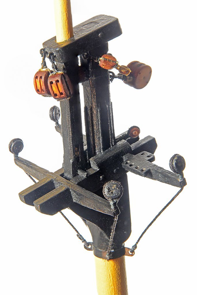
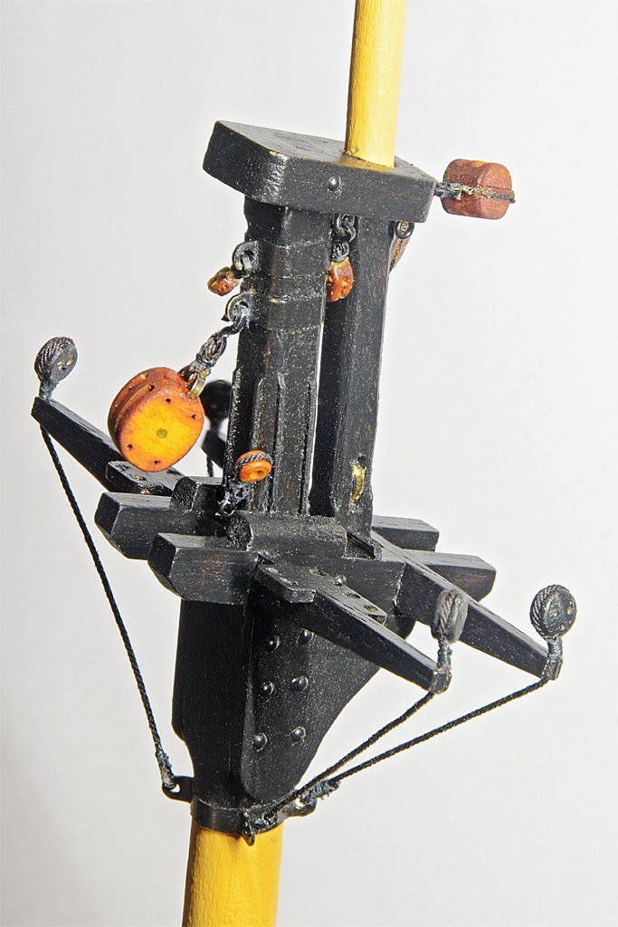
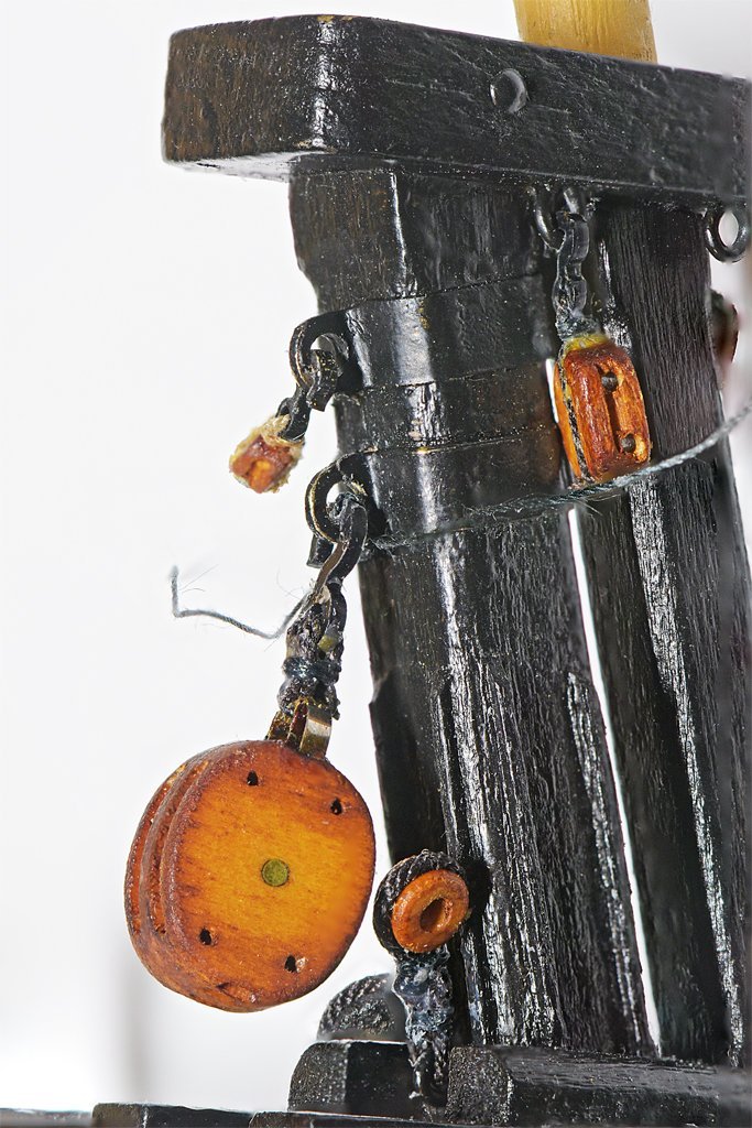
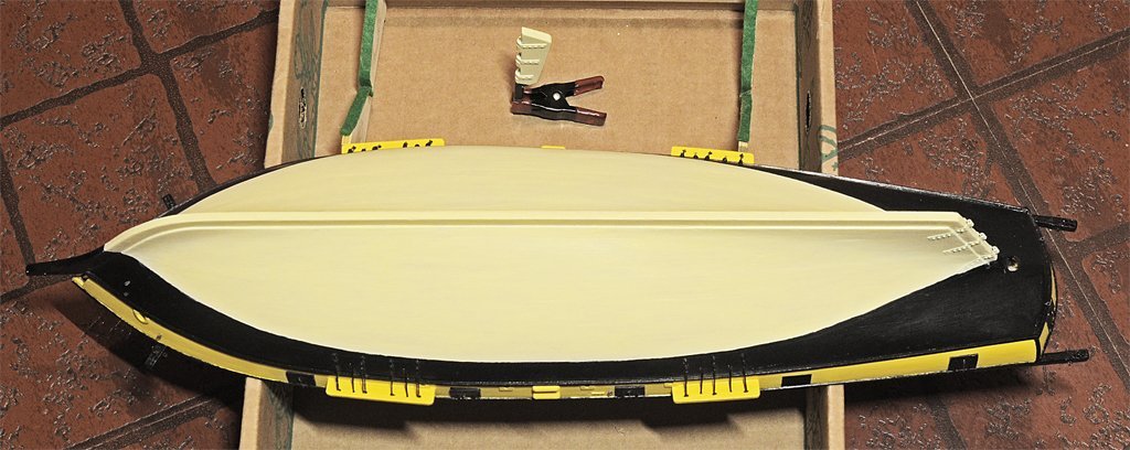
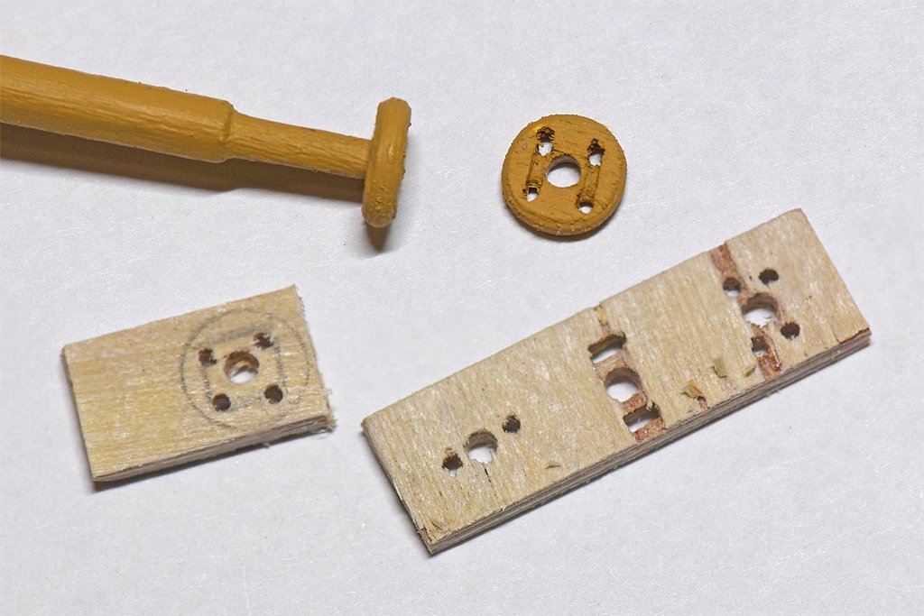
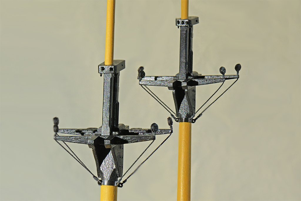
More work on the masts and bowsprit in preparation for starting the rigging. First are the trucks at the mast tops. These are about 0.20 inch or 5 mm diameter and are supposed to have two sheaves for raising flags and pennants. I just made two pairs of holes and cut a channel between them to simulate the sheave. The material is 1/16 inch (1.58 mm) aircraft plywood - I tried making them out of regular wood and it kept splitting as I was drilling and shaping them. I didn't have 1/16 inch plywood, but I did have 1/32 inch (0.8 mm) plywood, so I glued two pieces together. It took several attempts to get three pieces - one spare in case another one disappeared. The mast tops have a bunch of blocks for running rigging attached to them. I wanted to get these in place before installing the spars and booms (yet to be made) and placing the shrouds. Rigging the tiny blocks is tedious! I used Syren rope (on the metal thimble) for the pendants and Syren hooks. The seizing is a very tiny (0.005 inch or 0.13 mm) black line (small stuff) that I got years ago with some model kit - maybe even this one. I tie an overhand knot around the ropes and add a drop of white glue. Then I wrap (serve) the line around the rope and finish the seizing with another overhand knot. The seizing is then soaked in white glue and after it dries the ends of the rope and seizing are trimmed. Here is the top of the fore mast. The main mast top is a work in progress. The large (5/16 inch or 8 mm) double block for the gaff peak halliard caused a bit of a problem. The 5 mm hook fit loosely into the hole in the mast band, and could be shaken off fairly easily. I tried mousing it but the knot kept slipping off (this is pretty small work). Here is my solution. I tied an overhand knot of the 0.005 inch (0.13mm) small stuff around the hook, and then another overhand knot around the mast band eye. A small drop of white glue secured the knots. The knots were positioned so they are under the hook and mast band when the block is rigged, and will not be visible. Here you can see the loose ends of the small stuff while the glue dried. Then the ends were trimmed back to the knots. While I was working on all of the small parts I also painted the bottom of the hull. I used a mixture of white paint with a drop of yellow to simulate the tallow/white lead/turpentine mix used on small vessels. I have put this off while making all the deck furniture, cannons and masts because the hull was handled quite a bit. But this needed to be done before adding the anchors and starting the rigging.
-
Nice work! I understand your comments about how rigging the guns was tedious. I only had six 6-pounders and on 12-pounder to rig, and it seemed to take forever. I can't imaging rigging the guns on a 100 gun ship of the line!
- 562 replies
-
- 4
-

-
- vanguard models
- alert
- (and 2 more)
-
HM Cutter Cheerful 1806 by Erik W - 1:48 scale
Dr PR replied to Erik W's topic in - Build logs for subjects built 1801 - 1850
Erik, Your Cheerful build is very well executed! You are nowhere close to having the longest build. I am working on a model that I started in the 1980s. A new job, new wife, new house and new family really interfered with model making! But I am back at it and enjoying it very much. I may not have the longest build going either. I recall someone else saying they were working on a model they started in the '80s, or maybe earlier! -
Allan, Don't hold your breath! We are going on vacation next week and after that I will be doing taxes for a non-profit (Form 990) and that will take a week or two. Then I will be able to go back to work on the model and start the rigging.
-
I would urge caution about using a dye on blocks. I used Fiebing's Light Brown leather dye and was not happy with the results. I explain my concerns here: https://modelshipworld.com/topic/19611-albatros-by-dr-pr-mantua-scale-148-revenue-cutter-kitbash-about-1815/?do=findComment&comment=986904 What really peeved me is that Chuck's blocks are really nice and they came out looking terrible (in my opinion) because of the uneven staining. I think they would have come out better looking if they were painted. That's just my opinion, for what it is worth (they say you get what you pay for, so free opinions aren't worth much). I am also the fellow who put shellac on a block and had the dye bleed into the light tan rope. The reason for this was to hold the rope in shape tight through the block while in tension so I could work on the fall later. I often use shellac to secure lines temporarily so I don't have to work with too many "moving parts." I should have known better! Both the dye and the shellac are alcohol based and the alcohol on the rope wicked the dye out of the block, even though it had been weeks since the blocks were dyed. I think I can brush alcohol onto the rope and wick some of the stain out with a paper towel, but I haven't tried that yet.
-
Charlie, This is tricky! I loop the shroud around the deadeye and the pull the end of the line tight (but not too tight!). Then the loose end can be clipped to the standing part of the shroud while you add seizing the secure the shroud around the deadeye. This is tricky because if you pull a shroud too tight you may bend the mast and cause other shrouds to sag. You want the mast to rise straight vertically, so bending it is not good. I have rigged shrouds on several sailing ship models and somehow got them all to come out taut and not sagging. But I suspect this was more luck than technique! I am about ready to rig the shrouds on my current model and have been giving some thought to this. The way they did this on sailing ships (see Darcy Lever's The Young Sea Officer's Sheet Anchor) was to rig a tackle to the end of the shroud and haul on it to stretch the shroud tight before securing it with seizing. I may try something like this, using rubber bands to tension all of the shrouds before tying the seizing on any of them. You can rig all of the shrouds on a mast temporarily by using use small clips to hold the loose ends to the vertical shroud lines. Then after all are set up and nice and straight you can add the seizing. I want a bit of sag to the ratlines, to look like they have been used for climbing. For this I paint the ratlines with shellac (clear dope, white glue, whatever) and then hang something on each catenary between the shrouds until the shellac sets.
-
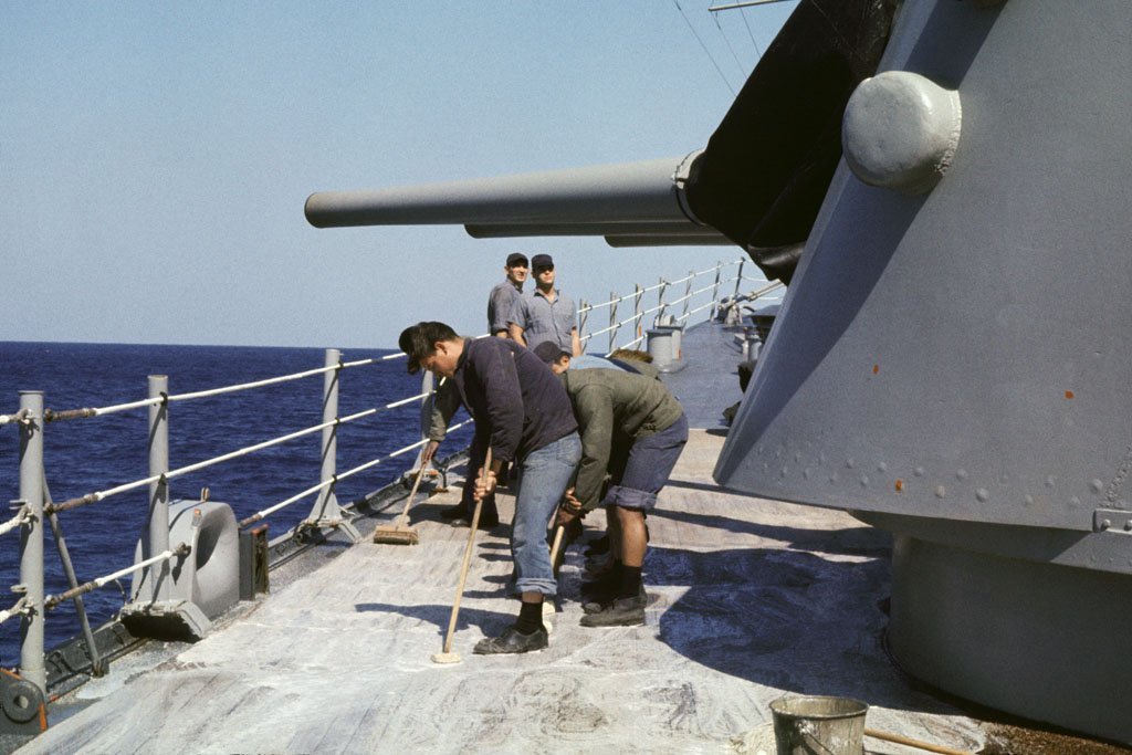
I would like to second Gary's comment about keeping the crew busy. It would take only a couple dozen seamen to operate a ship, leaving hundreds of bored sailors and marines nothing to do but get into trouble when the ship was not in combat. Holystoning, fancy rope work, polishing brass, painting and such gave them something to do. That was true when I was in the Navy in the 1970s. We had a crew of 1200 and only a few dozen were needed to run the ship. The primary way to keep sailors busy was chipping paint and then repainting. When I was a brand new Ensign I once asked why the Navy didn't use epoxy paints (like we used in the magazines) topside since it would last a lot longer than the apparently water soluble paint that was used. A senior officer replied that they wanted paint that didn't hold up at sea so they could keep the crew busy. Holystoning also kept men busy, but the primary purpose was to keep the Admiral's decks nice and white. Some type of bleach (we used oxalic acid on a minesweeper, but I don't recall what was used on the cruiser) was added to the scrub water, and old fire bricks from the boilers were the stones. They were pushed around with broom handles fitted into holes in the stones. I don't recall sand being used. Salt water from the fire mains was used to wash the decks afterwards. I don't know how true this is, but I have heard the term "holystoning" came from the practice of stealing tomb stones from a church cemetery in Portsmouth, England. There were no boilers to supply fire brick on sailing ships, and the tombstones were a good material for scrubbing decks.
-
Pandora 1831 Brigantine Rigging and Masting
Dr PR replied to michaelpsutton2's topic in Masting, rigging and sails
Michael, I am not familiar with this ship, but here are some observations. 1. The fore gaff would probably have jaws around the mast. This allows the gaff and sail to be lowered. If it was mounted on a fixed swivel the gaff could not be lowered. This was common on large steel masted ships of the late 1800s, but not on the smaller vessels of the 1700s and early 1800s. The clue here would be a throat halliard connected to the gaff at the jaws. This would only be used to lower a gaff with jaws. I can't tell from the drawing if there is one. 2. The staysail could be flying. Underhill's Sailing Ship Rigs and Rigging (page 93) calls this the main topgallant staysail because it connects to the upper top. If it was not laced to the stay that would allow it to be lowered to the deck without sending anyone aloft. The main gaff topsail is rigged this way, and the fore royal spar was almost certainly rigged this way too. For that matter, the fore topgallant spar could be rigged to be lowered and raised from the deck. This allowed rapid changes of sail and reduction of weight up high. This was important on ships like this that had a vary large sail area relative to the displacement. They were prone to being blown over and capsizing in strong winds. There are quite a few historical accounts of this happening. 3. The foot of the main gaff sail (main sail) is not laced to the boom (on many vessels it was). It is "loose footed" with attachments to the boom only at the tack and clew. The fore gaff sail is loose footed and boomless. The loose footed sails could be reefed very quickly with brails. 4. Interesting that you call this a brigantine (hermaphrodite brig). Brigantines normally would not have a gaff foresail. It looks like a topsail schooner. However, the diagram does show faint outlines of two more triangular sails (middle staysail and main staysail) between the main mast and fore mast, and that is characteristic of a brigantine. So sometimes the vessel could be flying a schooner rig and the brigantine rig at other times. The distinction between a brigantine and topsail schooner is somewhat vague because some vessels could be both. -
18-Pounder Pivot Gun
Dr PR replied to AndyHall's topic in CAD and 3D Modelling/Drafting Plans with Software
Here are a couple of links to another pivot gun model based mainly on Chapelle's drawings. The cannon is kit material and not really to scale. The rest of the gun is. https://modelshipworld.com/topic/19611-albatros-by-dr-pr-mantua-scale-148-revenue-cutter-kitbash-about-1815/?do=findComment&comment=1003991 https://modelshipworld.com/topic/19611-albatros-by-dr-pr-mantua-scale-148-revenue-cutter-kitbash-about-1815/?do=findComment&comment=1004278 -
Gregory, It was plain tap water. Several other modelers have recommended diluting the Brass Black 50:50 with water to avoid excess flaking. And I found 5 minutes was long enough to blacken brass and tin/lead solder. Then there still is some black that will rub off the parts, but not much. Some people "pickle" the parts in warm Sparex #2 (sodium bisulfate) instead of vinegar to give the parts some "tooth." That might result in a more uniform finish, but I haven't tried that yet (I do have a package of Sparex on hand).
-
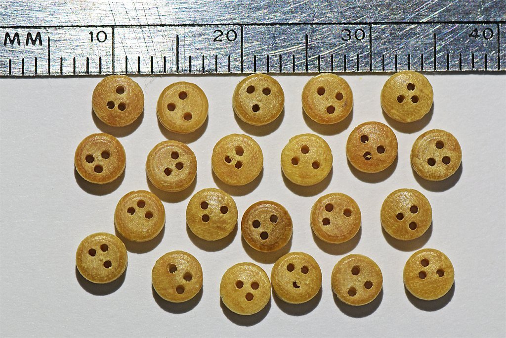
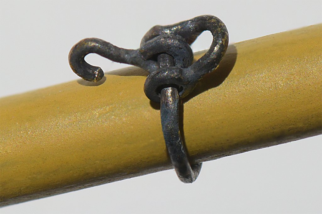
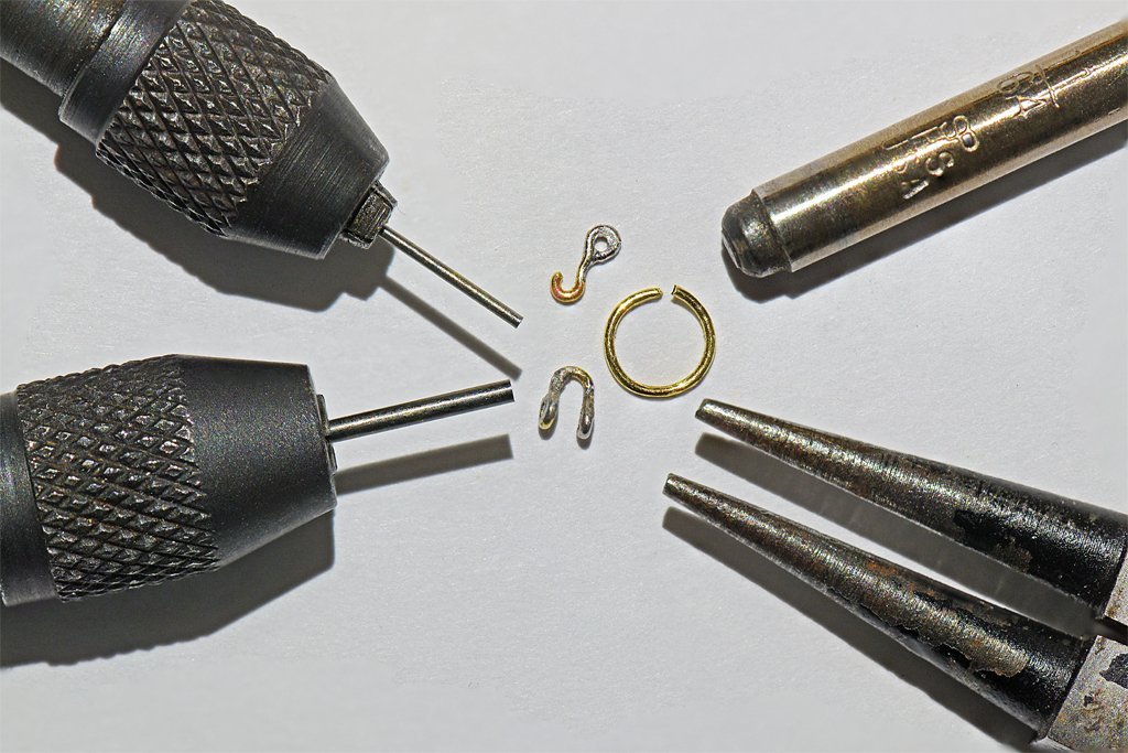
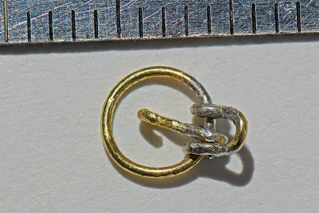
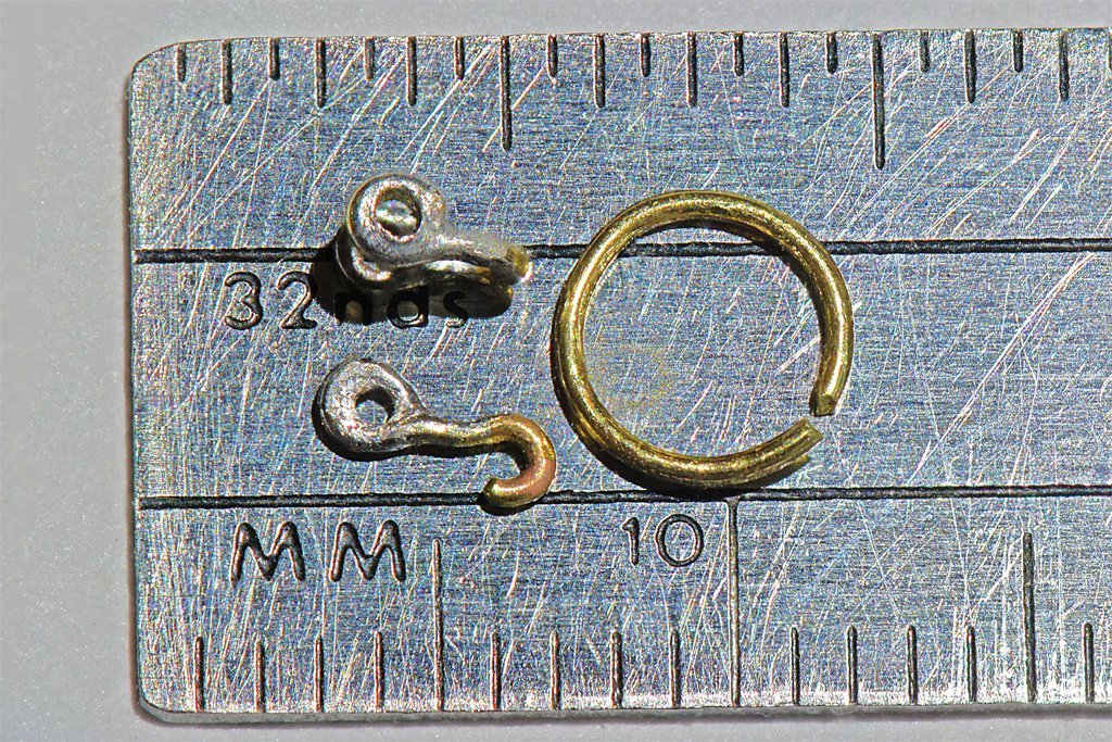
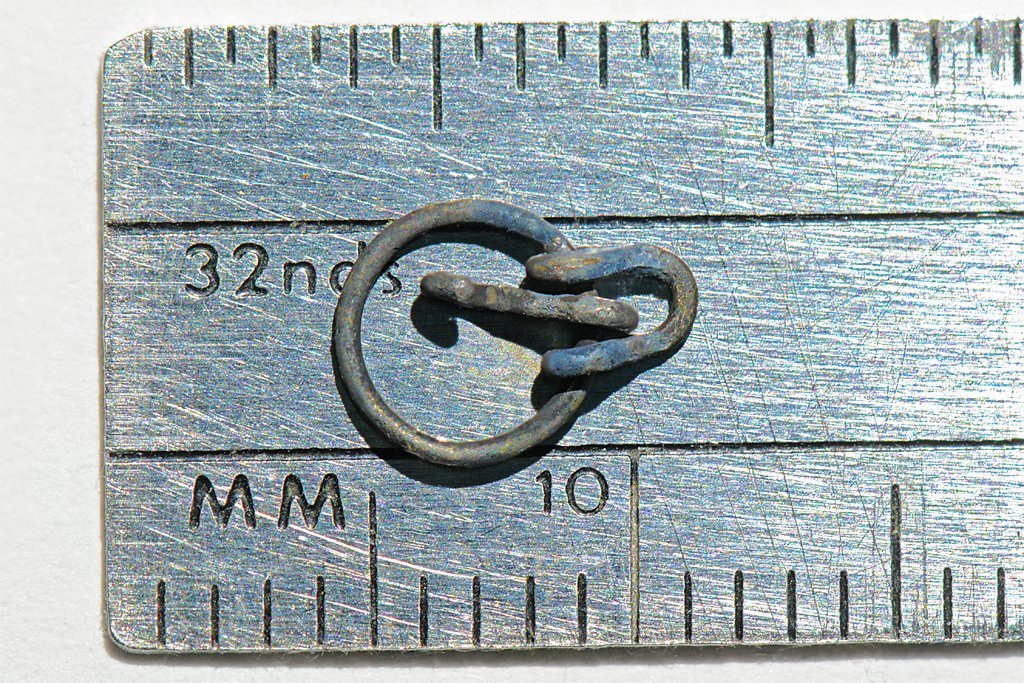
I have been preparing for rigging the masts and bowsprit, finishing details like cleats for the anchor rigging and such. Part of the job is to go back through my drawings to determine rope and block sizes for all the rigging. I started with the futtock shrouds on the mast tops. These have deadeyes at the ends of the crosstrees and ropes that lead down to the futtock necklaces around the mast below the cheeks. I wanted to use deadeyes that were smaller than the 5 mm parts I used on the channels. I looked around and found some Amati 3 mm boxwood deadeyes. These turned out to be 3.4 mm diameter, but this is good enough. I plan to use these at a dozen or more places where there are lines and stays that require periodic retensioning, so I ordered two bags of 20. That was a good thing, because there were no two pieces alike! Some have holes that are not symmetrically placed, and in some the holes are absurdly close together. Looks like they were drilled by hand! I was able to pick out 16 that were reasonably symmetrical and close enough to be used together for the shrouds. Maybe I can find enough pairs that are similar enough to finish the nine lines on the bowsprit. **** I am also working on attaching the blocks and deadeyes for the bowsprit assembly before it is attached to the hull. First up on that job was making the traveller for the flying jib stay. I consulted Lees, Marquardt and Lever to determine the size and type of traveller suitable for a small vessel. The ring diameter should be 1 1/4 times the diameter of the jib boom, and the wire should be between 0.013" (0.33 mm) and 0.026" (0.66 mm) at 1:48 scale. The jib boom is 0.14" (3.56 mm) diameter at the bowsprit cap, so the traveller ring should be about 0.175" (4.45 mm) inside diameter. I decided to use 0.020" (0.5 mm) hard brass rod for the ring, shackle and hook. This stuff is pretty small, and the shackle was something of a challenge. I used a 0.024" (0.6 mm) drill bit inserted into a pin vise with the shaft sticking out as a mandrel for shaping the eyes on the shackle and hook. A 0.044" (1.1 mm) bit in another pin vise was the mandrel for forming the "U" of the shackle. A 11/64" (0.172 ", 4.4 mm) drill bit was the mandrel for shaping the traveller ring. I used chain nosed pliers to start the eyes and normal needle nose pliers to finish bending the wire around the drill bits. After the eyes were formed they were soldered closed using 60:40 tin/lead resin core solder (what I have on hand) and a citric acid liquid flux. Note: After the shackle and hook were added to the ring the assembly is a bit too tight fit around the jib boom at its widest point near the bowsprit cap. I should have used the next largest drill bit (3/16", 0.187", 4.7 mm) for the mandrel to make the traveller ring. I have seen master modelers turn out tiny shackles in quantity, every one a perfect replica, but this was my first attempt and I wasn't sure what I would get. I think the results are OK for this project. The next step was to solder the ring closed - with the hook inside the shackle, and both on the ring. I washed the traveller in warm water to remove the liquid flux, then washed in acetone to remove the resin flux from the solder. Then I etched it with white vinegar for a while. After washing and drying I used a five minute soak in a 50:50 mixture of Birchwood Casey Brass Black and water to finish it. The results are interesting. I seem to have discovered a way to "antique" the metal. Rather than the dull black I expected, the part looked like it had been dredged up from the mud over a centuries old shipwreck! But after wiping it a bit with a paper towel it looks pretty good on the jib boom. I'll keep it!
-
I recently bought a cast metal figure to be the "Captain" of my build. With hat the figure is 35 mm high. Without the hat the fellow would be about 32mm (with boots on). That is an odd size: 1:48 32 mm = 1.536 meters = 4.94 feet 1:50 32 mm = 1.600 meters = 5.14 feet 1:64 32 mm = 2.048 meters = 6.59 feet 1:72 32 mm = 2.304 meters = 7.41 feet So at common modeling scales either the guy is very short or very tall. If we assume and average fellow was 5.67 feet (5 foot 8 inches) = 1.762 meters then the figure would be 1:55 scale! ?WTF Who models at 1:55?? Maybe sailors were just a lot shorter 200 years ago? Midshipman maybe?
-
6-pounder, Royal Navy cannon barrel - George III era
Dr PR replied to Gabek's topic in 3D-Printing and Laser-Cutting.
I have seen this problem with Chitubox. With a single surface (like an "O") with a hole in it the hole is often filled in. But if I cut it into two "C" shaped surfaces fitted together to enclose the hole there isn't a problem. The gap between the two surfaces is zero thickness so it doesn't appear in the printed part. Since this seems to be a problem with different CAD programs and different slicers I suspect it is a problem in the STL file format, or at least the description telling how to create the STL object. -
Interesting. On the USS Oklahoma City CLG-5 during the Vietnam War our Marine detachment operated the 5"/38 gun mount. Regular Navy Bosun's Mates manned the 6"/47 turret. The Marine detachment (Mardet) guarded the nuclear weapons spaces 24/7 and were "on call" for Security Alert actions where the Marines manned stations on deck with pistols, rifles, machine guns and grenade launchers - basically a "repel boarders" type situation. And the Marines formed a shore party that could be sent ashore to scout/attack a hostile position - or perhaps board another vessel. This is pretty much the same duties for the Marines as 200 years earlier.
-
John, Jack and Chris, Thanks for your comments. Keep in mind that this is 1) a "theoretical" version of a revenue cutter, and 2) that I have discovered several errors in my work - all part of the learning experience. In fact, I am enjoying the learning more than the building.

