


Mahuna
-
Posts
1,500 -
Joined
-
Last visited
Content Type
Profiles
Forums
Gallery
Events
Posts posted by Mahuna
-
-
6 hours ago, michael mott said:
Hi Frank I just finished going through your whole build log..... Wow what a great model.
Michael
Thanks Michael, and welcome aboard.
52 minutes ago, John Allen said:Frank,
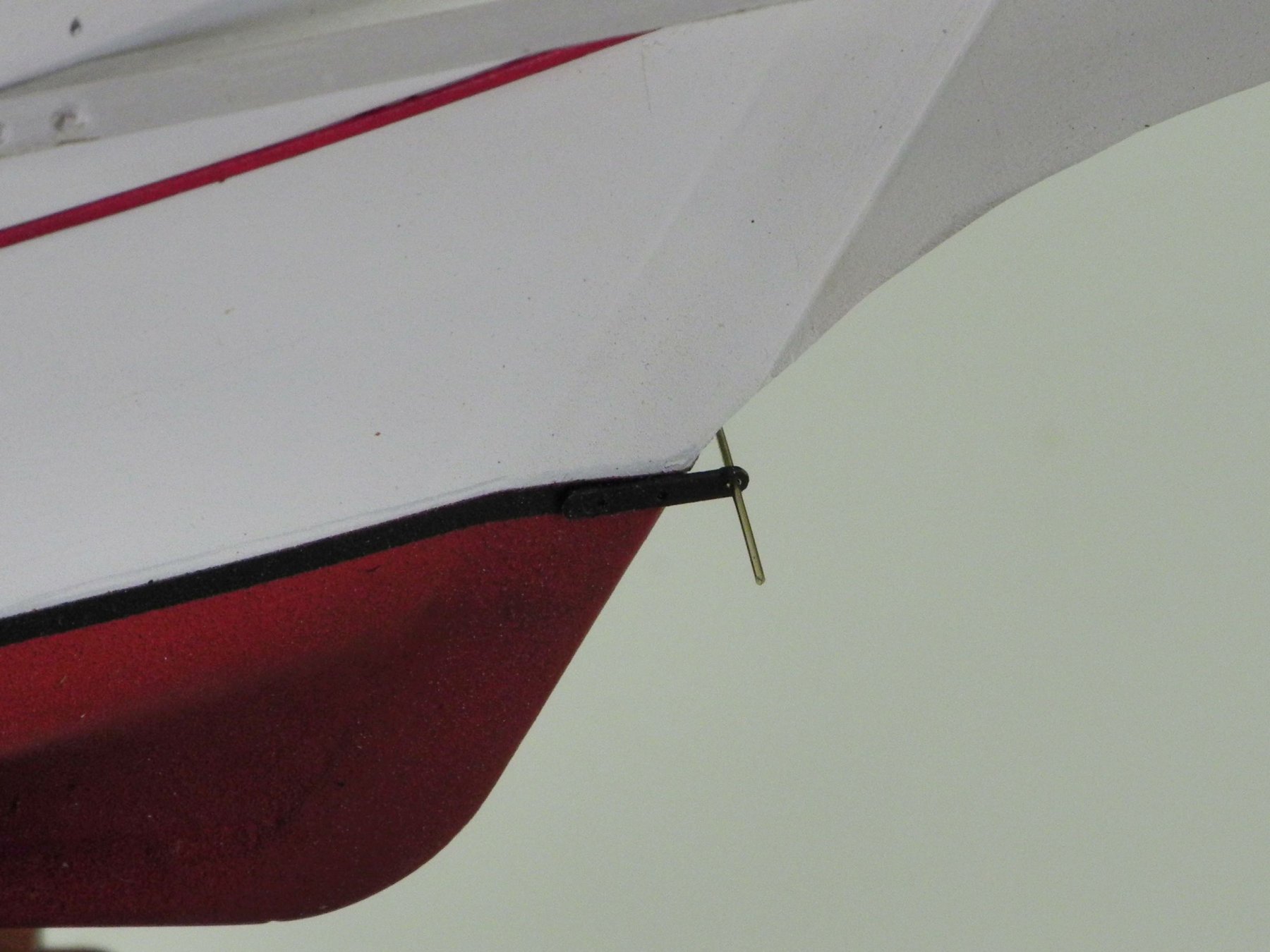
Just magnificent, what function does the 8oz? fishing lead weight held in place by 4 wires on the bowsprit do?
Thanks John. I have no idea how that weight got tangled there - I'll need to contact some friends who may know.
-
2 hours ago, HIPEXEC said:
Frank
I'm going to challenge you to help me Saturday with some mini metal work.
I’ll be happy to help, Rich, and I’m sure we’ll get some help from the other attendees. Looking forward to it - come hungry!
-
Thanks Popeye. I think I know how I'll do the tailboards, and I'm working on it now. Hopefully will have results to post in a couple of days. Stay tuned!
- Canute, thibaultron, Jack12477 and 2 others
-
 5
5
-
On 7/9/2018 at 6:56 AM, Jim Rogers said:
According to my communications and this photo sent to Sherline I am the only person to ever have this problem and they tell me they make no adapters to fix this problem. They told me to build an adapter. I find it real hard to believe they don’t have attachment to fix what appears to me to be a common issue. Right hand attachment plus rotary table with vise mounted on top does not align. Any suggestions
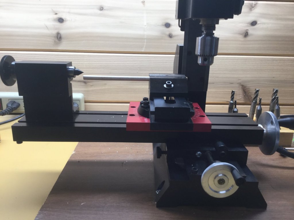
The photo shows a rotating mill base, not a rotary table. The right angle tail stock is designed to be used with the rotary table held in a vertical position, not with the rotating mill base.
- Canute and Jim Rogers
-
2
-
-
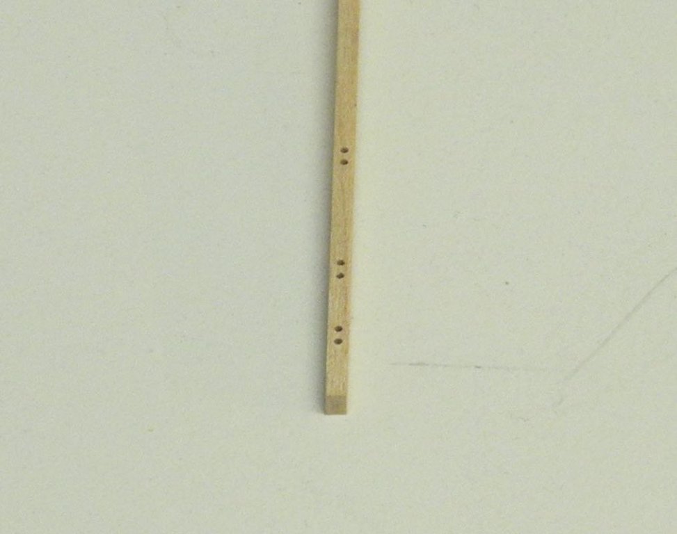
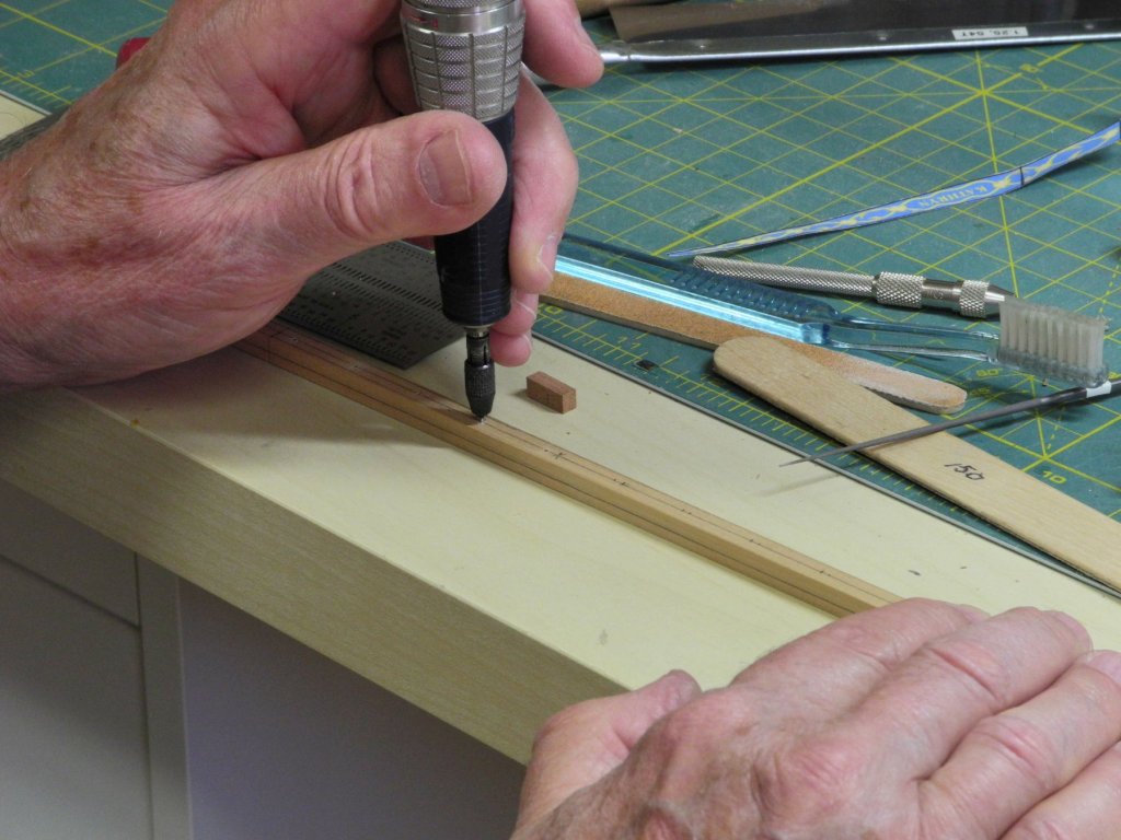
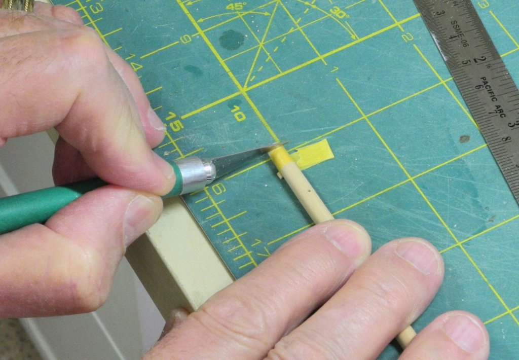
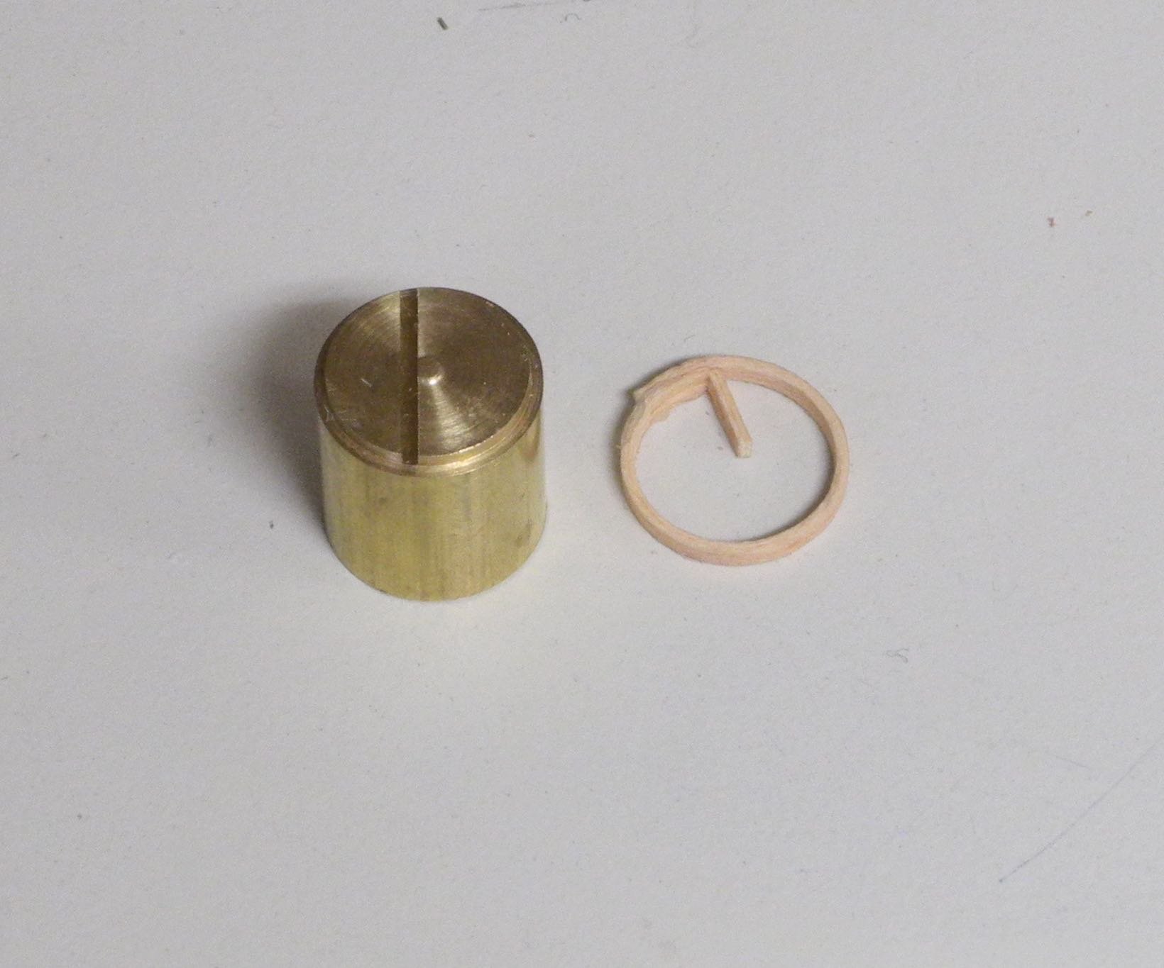
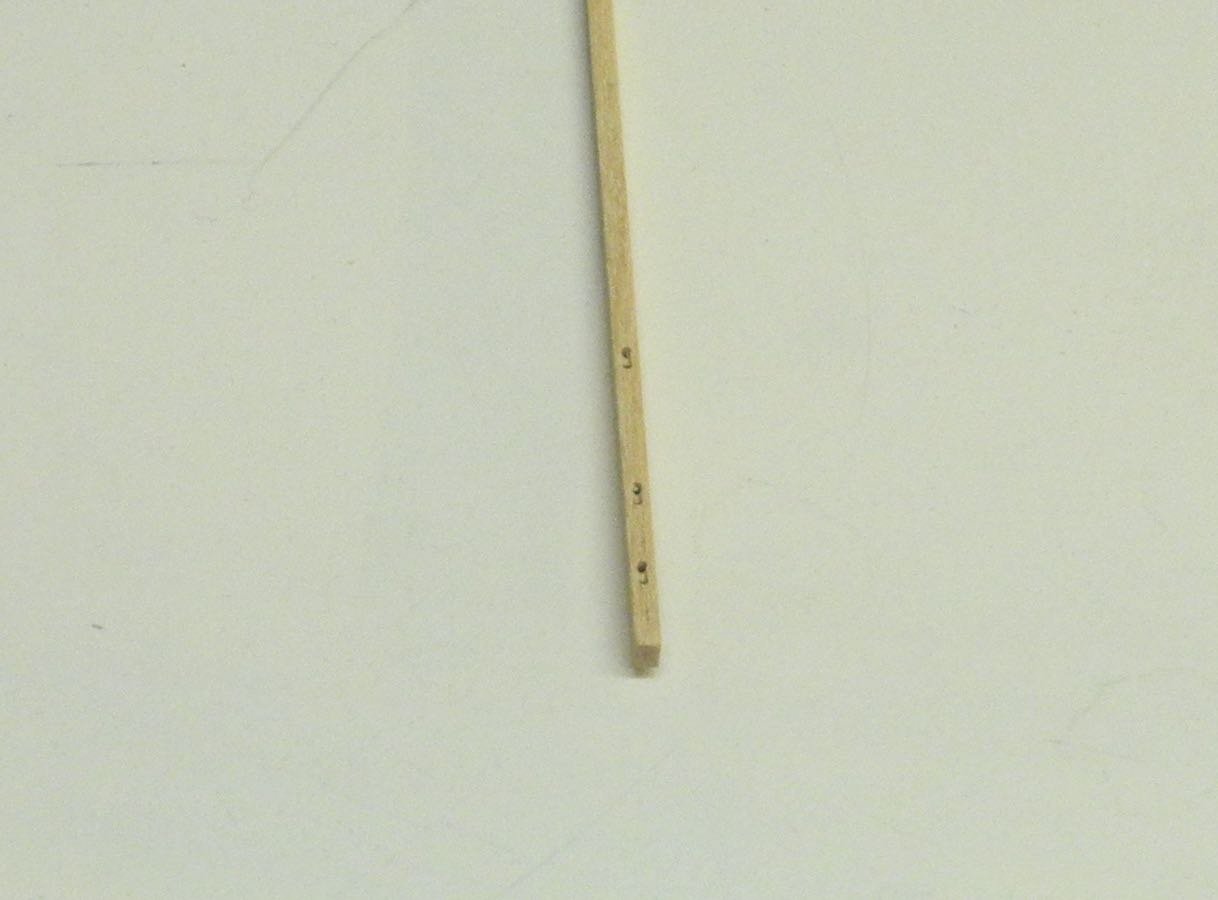
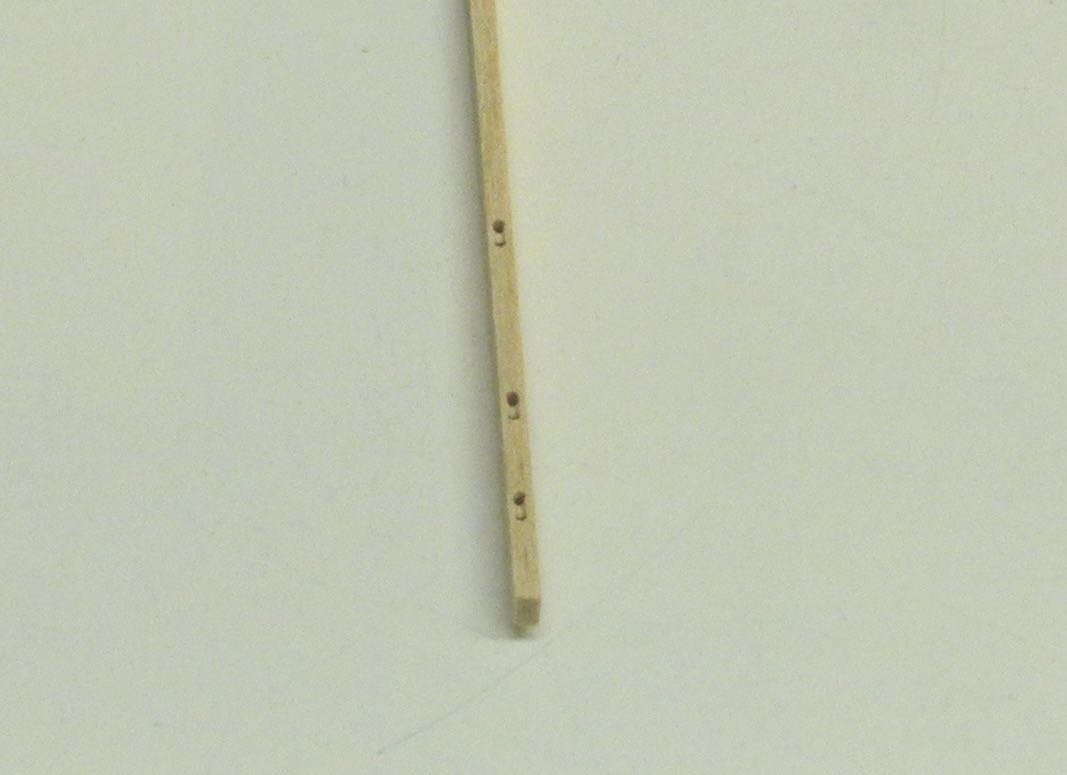
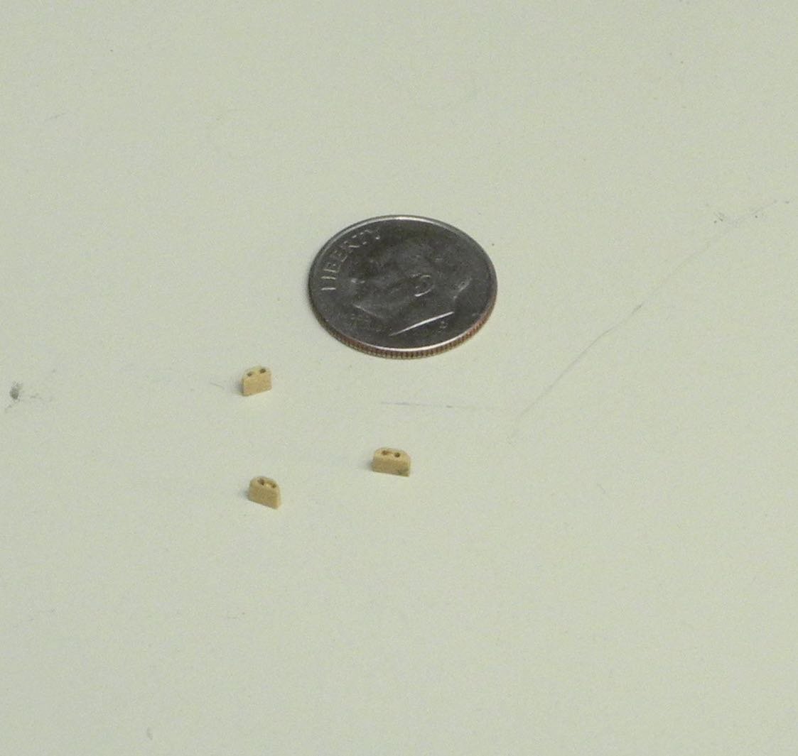
Part 72 –Mast Hoops
Kathryn has 17 mast hoops for the main sail. In the past I’ve tried making mast hoops from brown wrapping paper, but wasn’t satisfied with the results. I’ve also tried laser-cut mast hoops, but wasn’t able to find the right size, and I found that the hoops were very fragile because of the way they were cut across the grain.
I decided to try making my own by soaking thin strips of wood and bending them around a form. I tried using Castello, but found that it split when bent into a tight circle. I discovered that American Holly is much more flexible, so I decided to use that for the hoops.
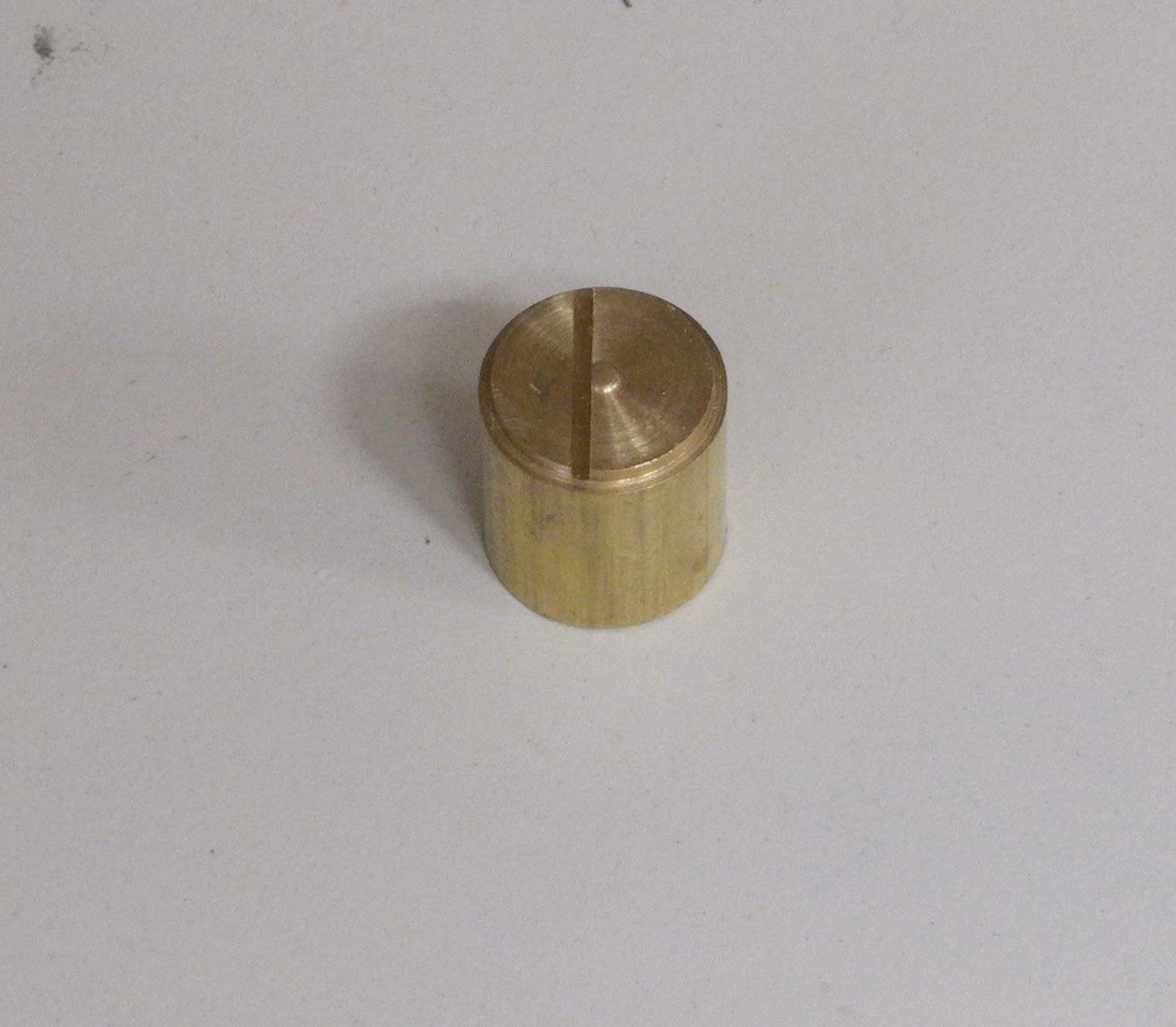
I made a form from a brass rod slightly larger than the inside diameter of the hoops. A ledge of the appropriate inside diameter was cut into the end of the rod, just deep enough to hold the height of the hoop. A slot was cut off-center.
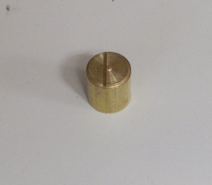
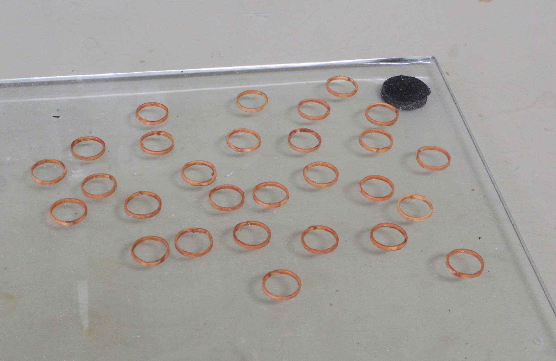
Sufficient strips of holly were cut so that I could produce about 25 hoops. These strips were stained with Colonial Maple – I stained them prior to making the hoops, because I thought there might be a problem coloring the hoops after they were glued together.
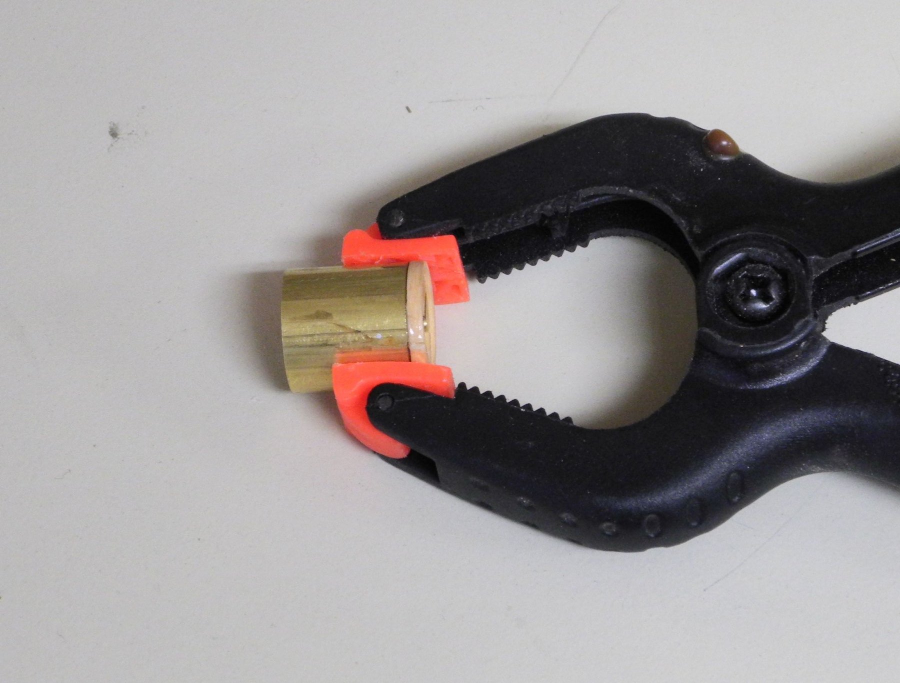
A strip for a hoop (about 2” long) was soaked in boiling water for a few hours, and then was wrapped around the form. An end of the strip was placed in the slot, and the strip was wrapped around the form, making sure that the edge of the hoop lay against the ledge – this ensured that the hoop would be straight. The hoop was then clamped and left to dry for at least 6 hours.
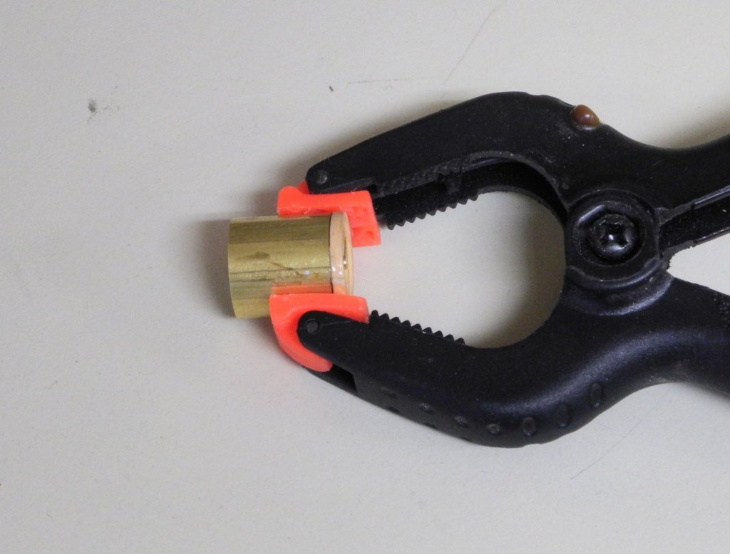
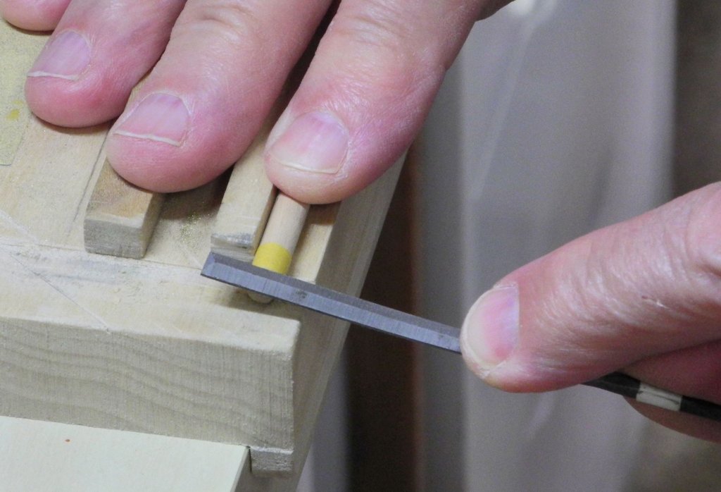
When dry, the hoop was then glued and held again in the form. The following photo shows a hoop after gluing.
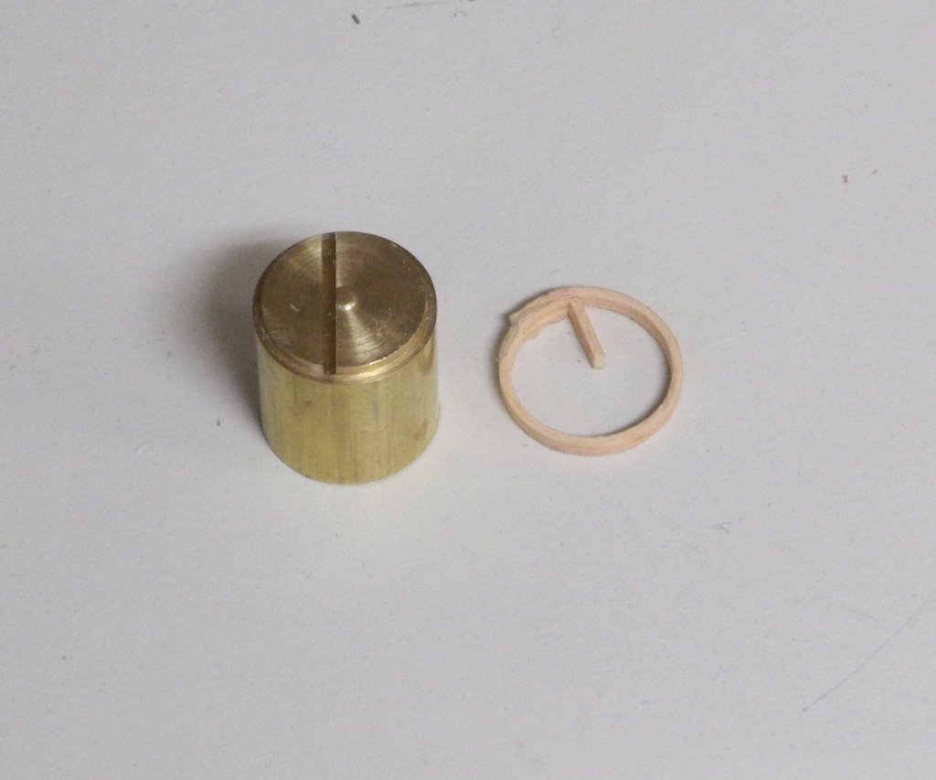
The inside end was clipped off and the inside diameter was smoothed with a diamond cylinder in the rotary tool. The outside diameter at the joint was reduced and smoothed. Any misalignment of the sides was corrected by sanding.
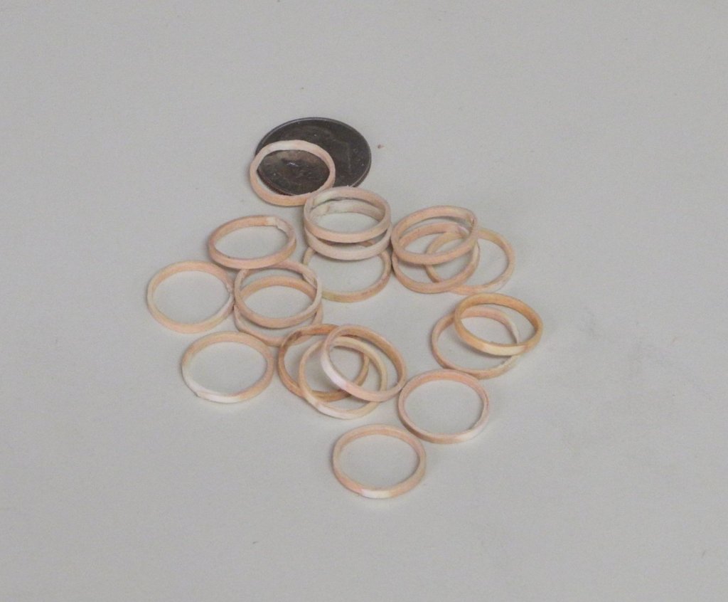
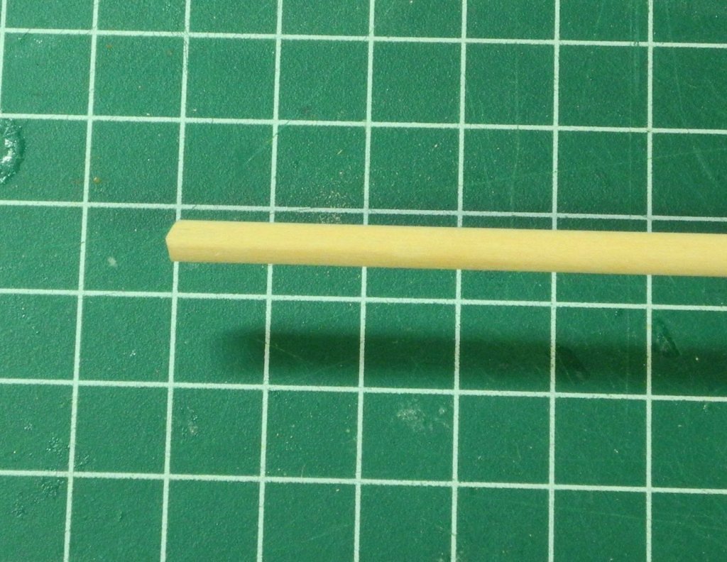
Using this process, 2 mast hoops per day were produced. After all of the hoops were finished they were dipped in stain to darken them, and then were finished with wipe-on poly and left to dry on a glass plate.
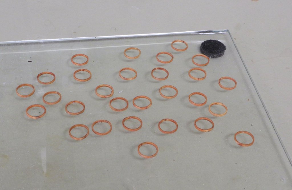
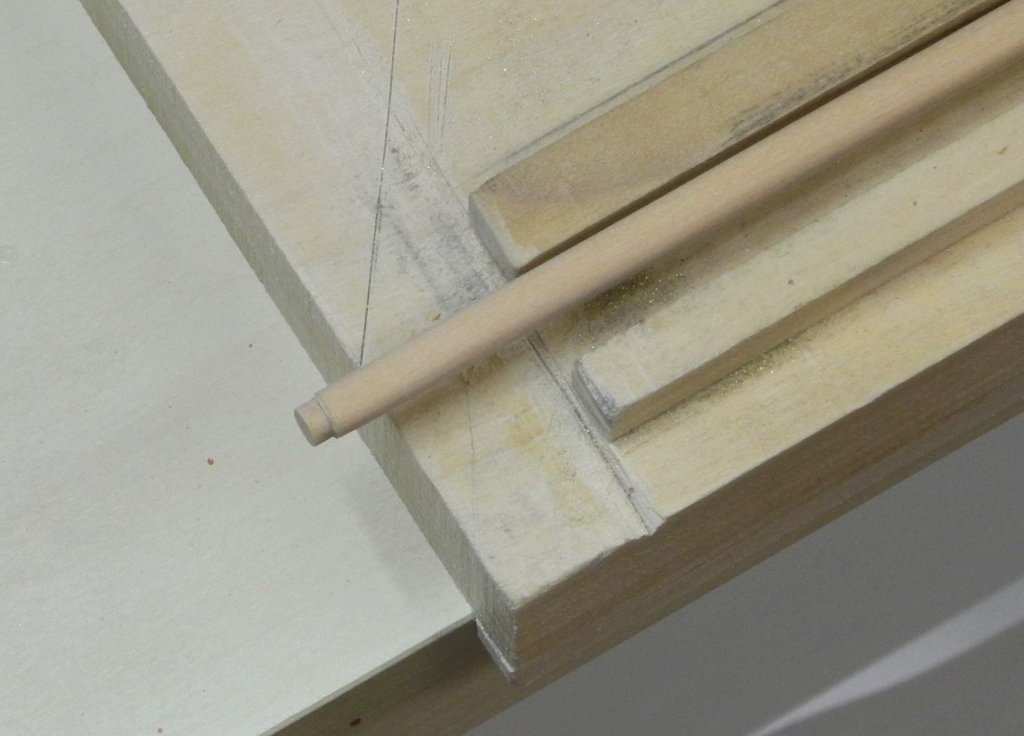
The following photo shows the mast hoops temporarily in place on the mast.
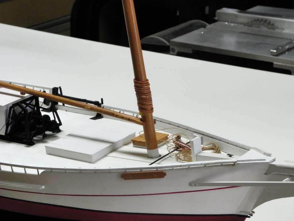
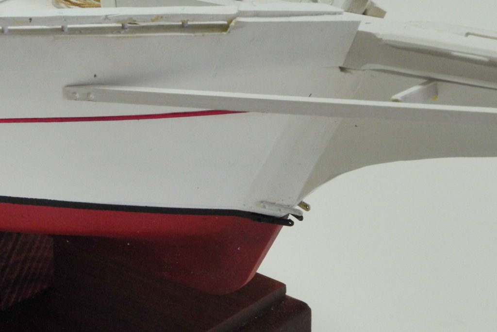
Also visible in the above photo is the breasthook that covers the bowsprit from the stem inboard. This was created by cutting and shaping a piece of flat stock 1/16" thick.
Every little step is bringing us closer to the start of rigging!
- usedtosail, hexnut, Canute and 12 others
-
15
-
Thanks for the input, Ron. The commercial printing service I mentioned was referred to me by an excellent military modeler, so I'll give it a shot. If it doesn't work I'll try what you recommend.
- Canute, mtaylor, popeye the sailor and 1 other
-
4
-
3 hours ago, mtaylor said:
Funny thing here Frank... not ha-ha but in a good way. I can't tell the difference between the pics of the real thing and the model except for what's under it. Water on the real, work table on the model. More than once without those visual cues, I've had to look pretty hard to tell which is which.
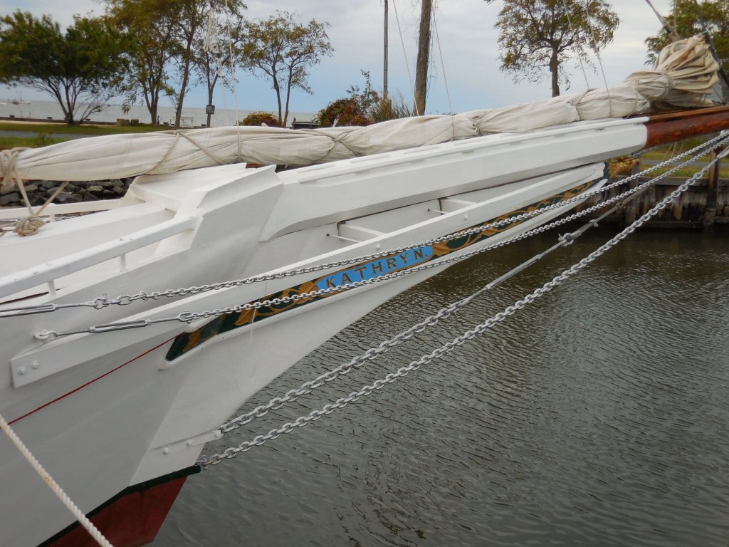
Thanks Mark. I've been fortunate that I was able to take a lot of photos during my two visits to Kathryn, and also have been able to find some really good photos form the recent rebuild. A good friend also shared some photos he took of Kathryn at the time of the HAER survey. These have all been a great help in trying to get the details right. I'm afraid I'm a little spoiled now, and I've been thinking of how different it will be when I work on my next model - with only the basic plans to go by.
3 hours ago, GuntherMT said:Great job, and I love the name plates. Going to have to remember this method!
Thanks Brian. I can't take credit for the method of taping and cutting the pieces as part of the laser etching. The tech in the trophy shop (very near to where you work, by the way) is the one who decided to use that approach, and it worked out really well.
- paulsutcliffe, mtaylor, druxey and 5 others
-
8
-
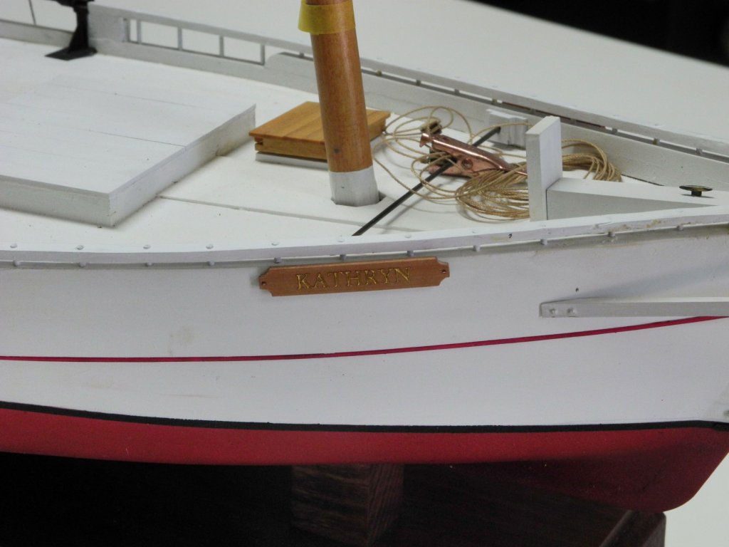
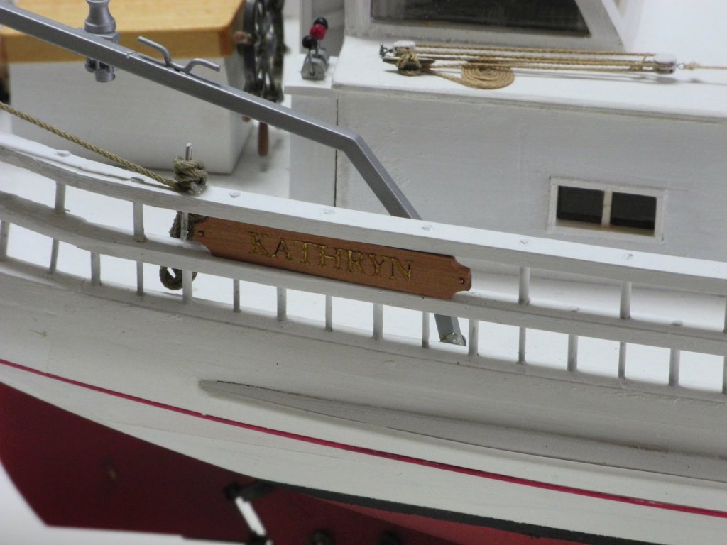
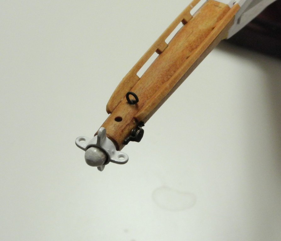
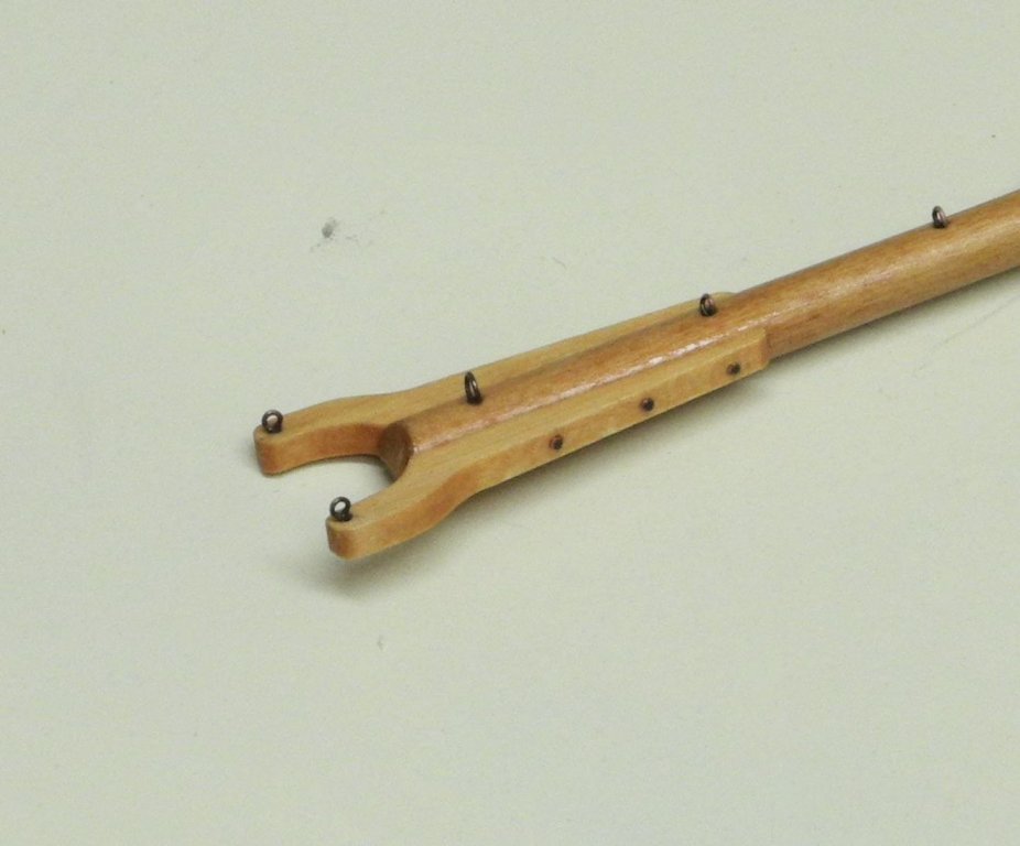
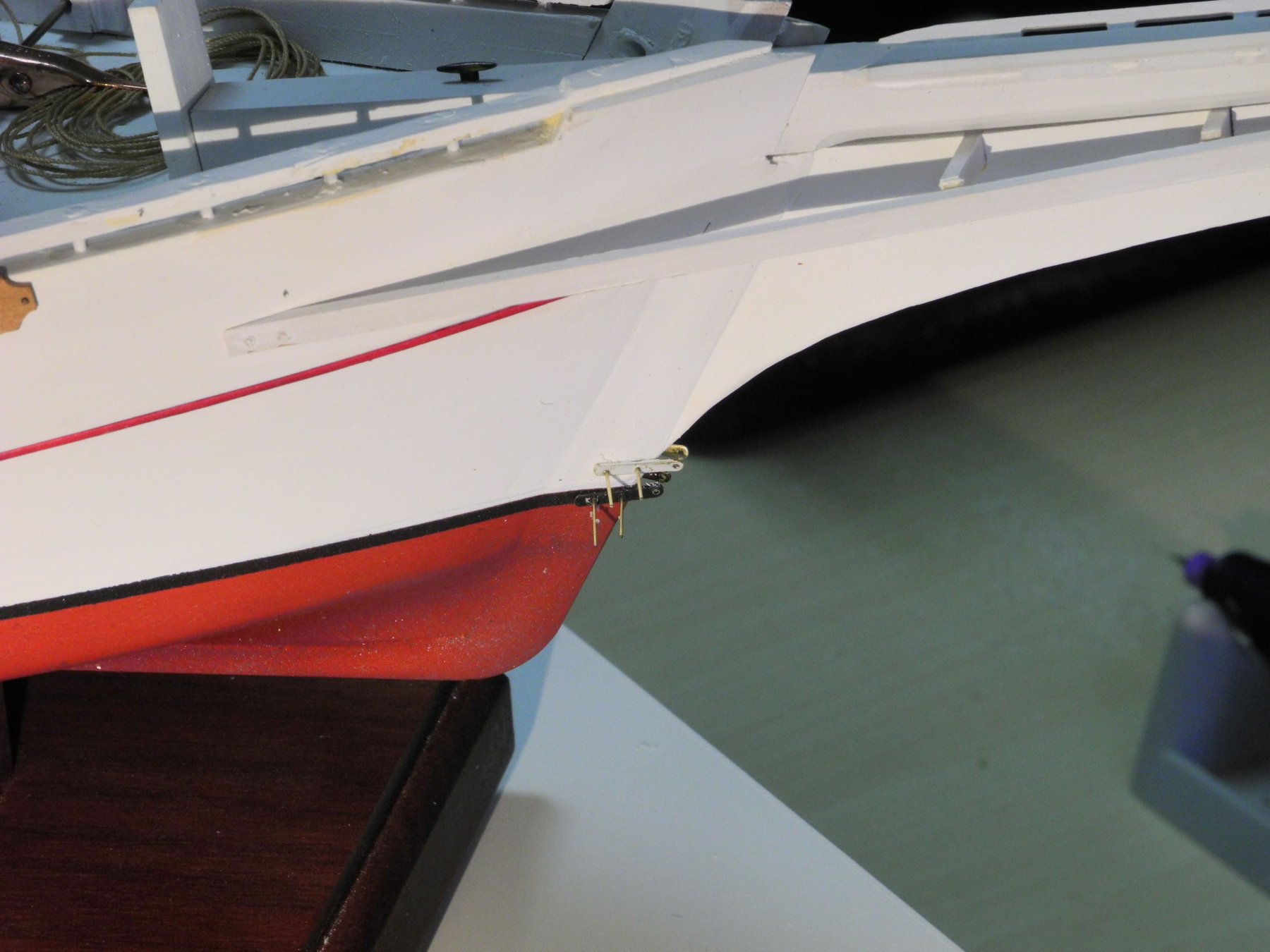
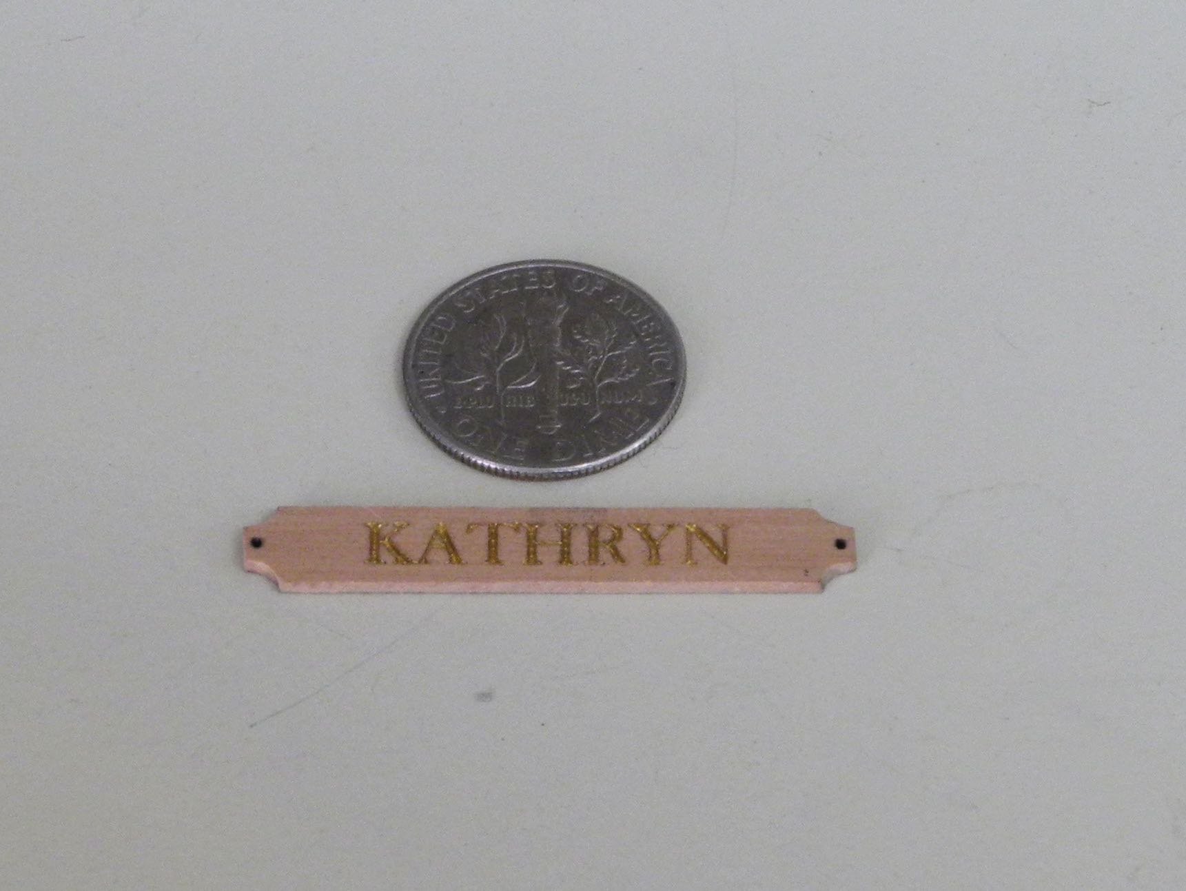
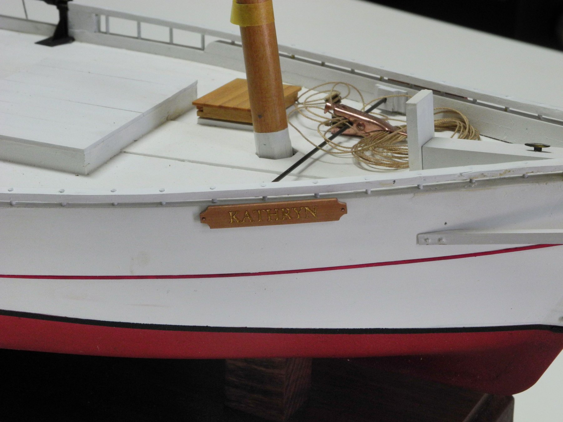
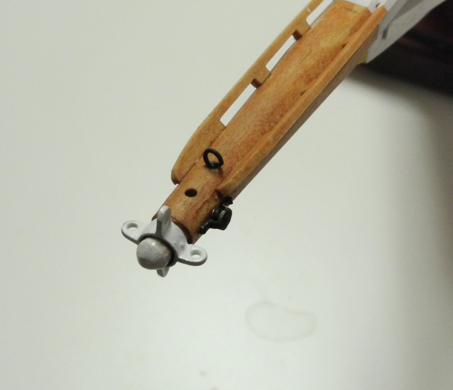
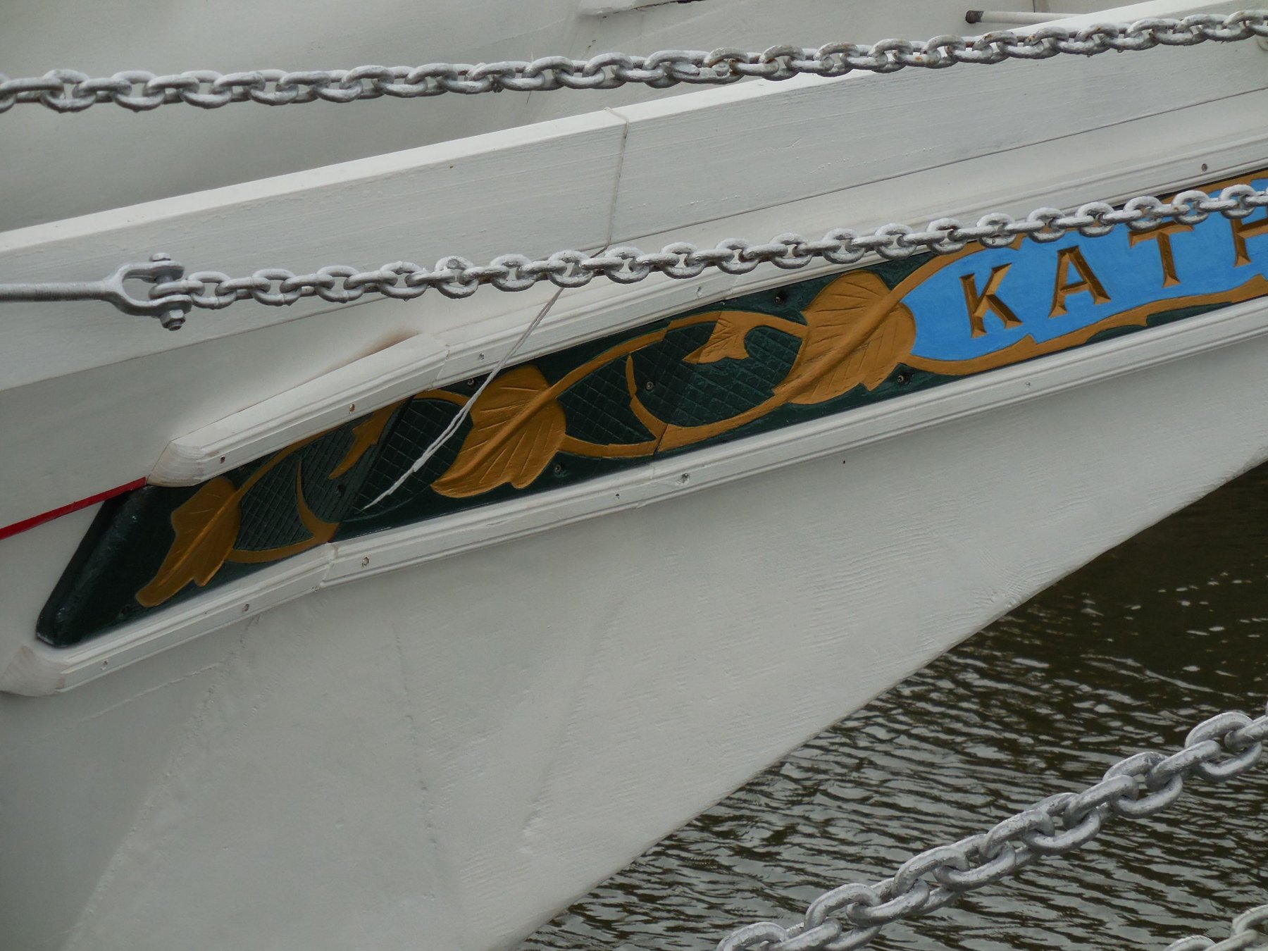
Part 71 –Bowsprit, Chain Brackets, Name Plates
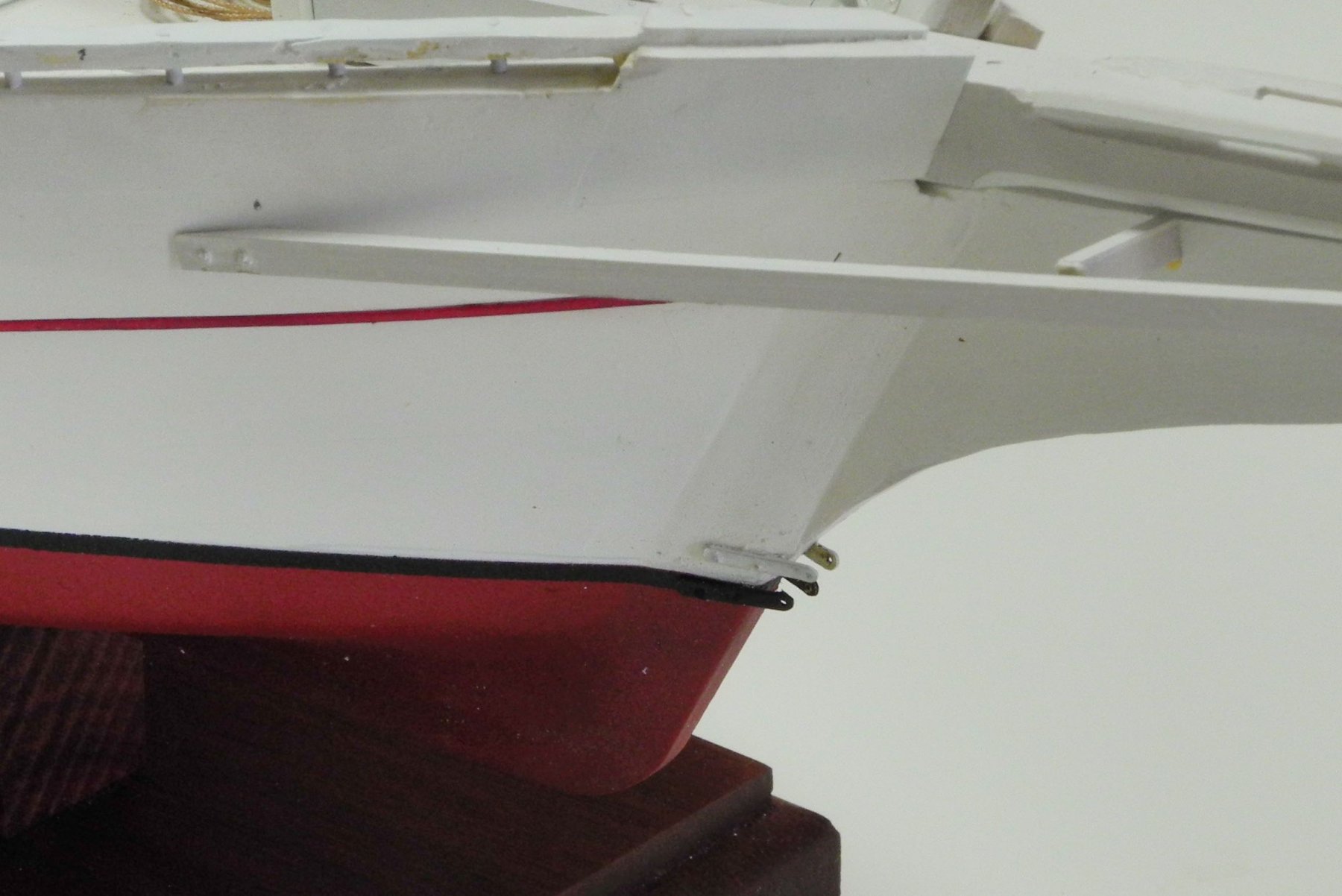
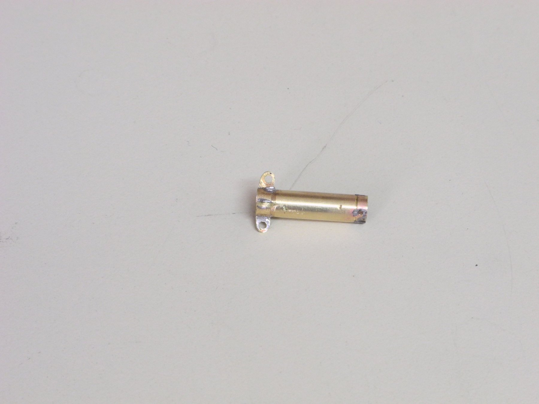
Now that all of the prep work on the bowsprit is completed, it was time to permanently mount the bowsprit. A hole was drilled through the bowsprit into the outer stem, and a 1/32” brass rod was used as a pin to lock the bowsprit in place.
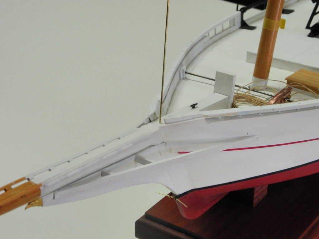
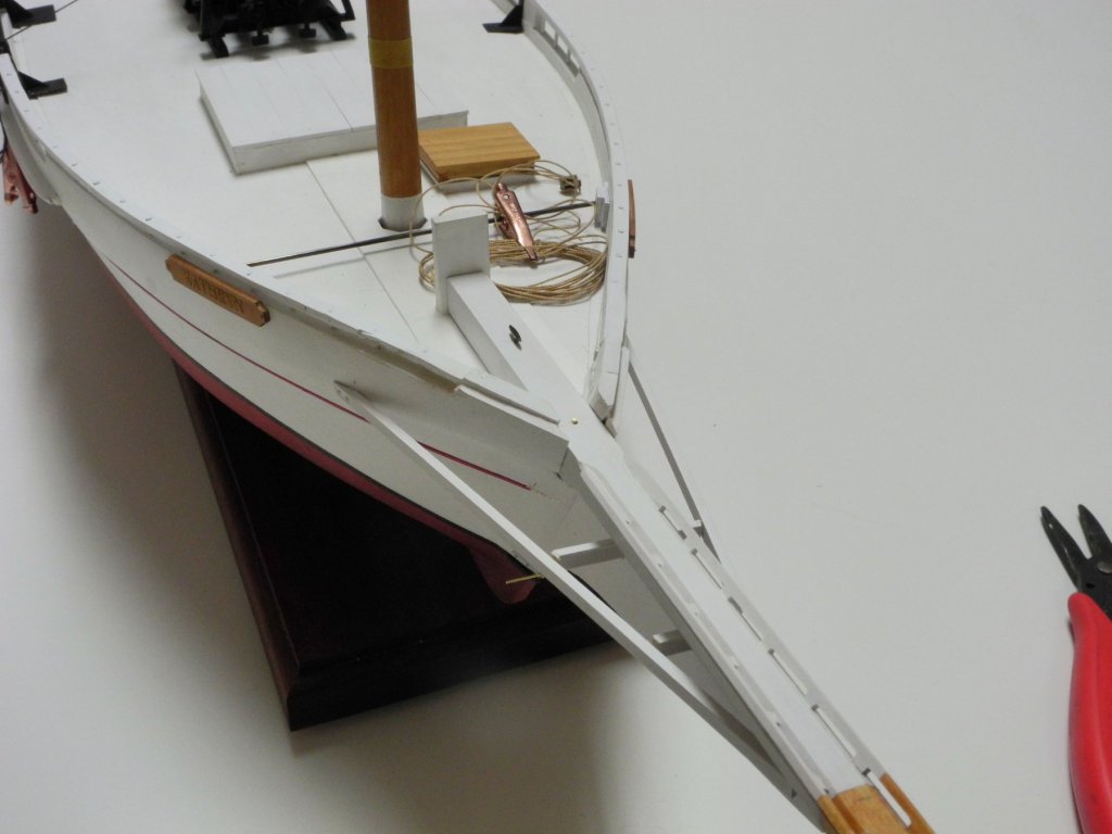
The Bob Stay and Jib Stay (or Forestay) are anchored to brackets at the waterline area of the bow.
The lower of the two chains is the Bob Stay, and is connected to the lowest tab on the Bowsprit Band. The upper chain is the Jib Stay, and this runs through a hole in the bowsprit to the area of the hounds on the mast.
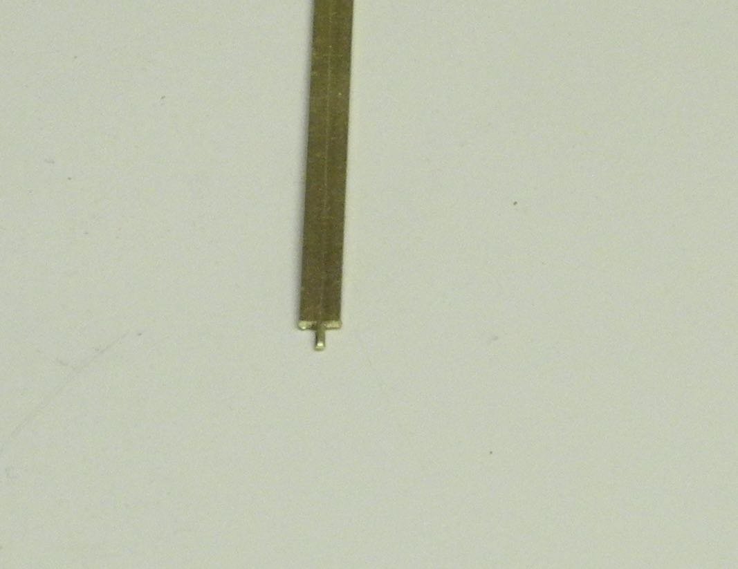
These brackets are installed on each side of the outer stem, and were made from separate pieces of 3/32” x .020” brass strip that were shaped and drilled and then painted while still off the model. An outer hole that extends forward of the outer stem is for support of a small post that has the chain attached to it. Two inner holes were predrilled to provide holes for pinning the bracket pieces to the lower stem.
The starboard bracket piece was the first to be installed, and then the port piece was installed using a small rod between the two to ensure alignment.


After both sides of both brackets were installed, the pinning holes were drilled through the brackets and into the stem. Pins made from .015” brass rod were CA glued in place and when dry were snipped.

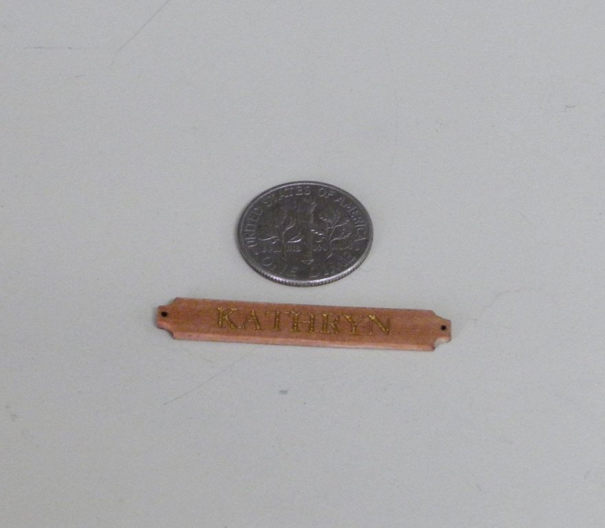
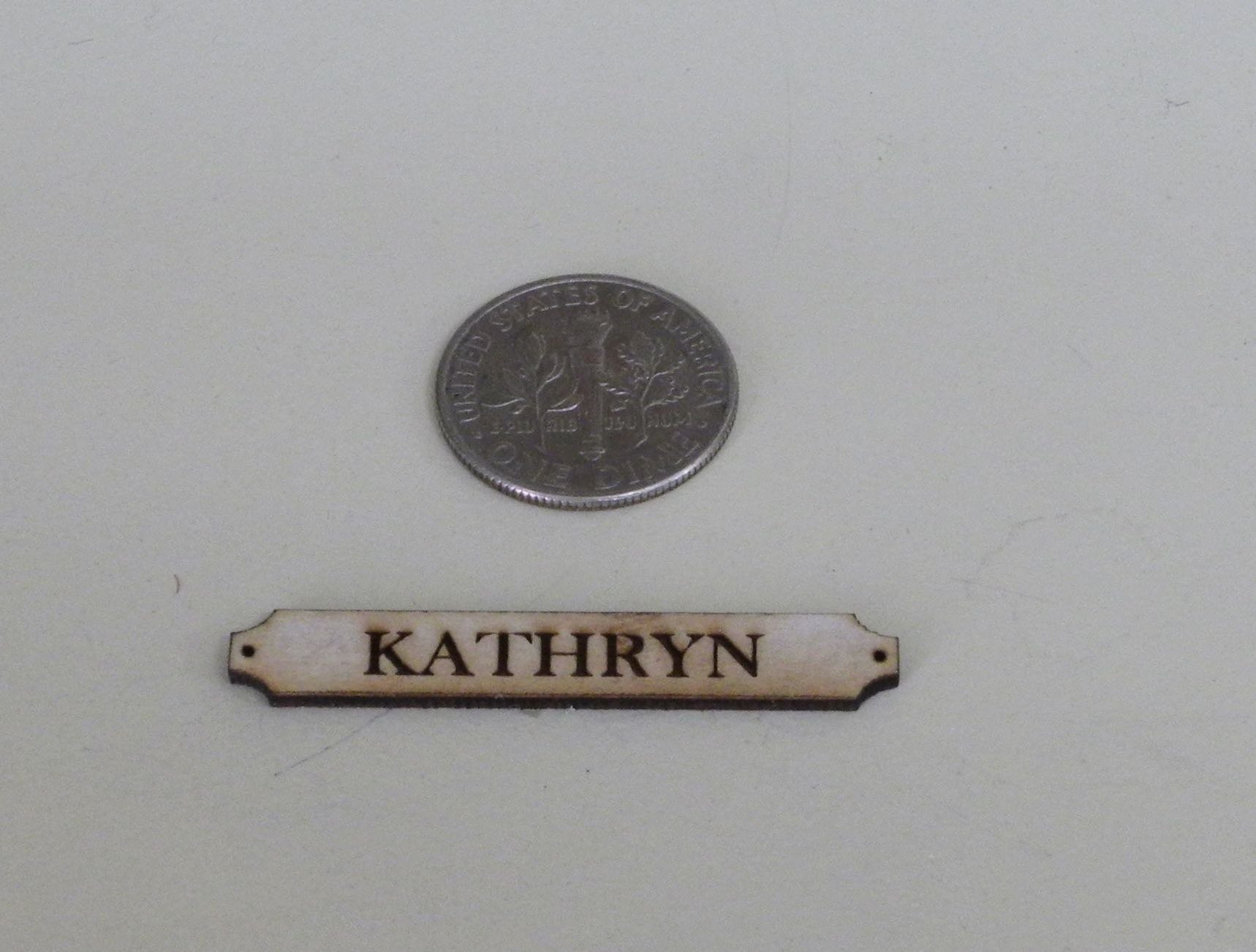
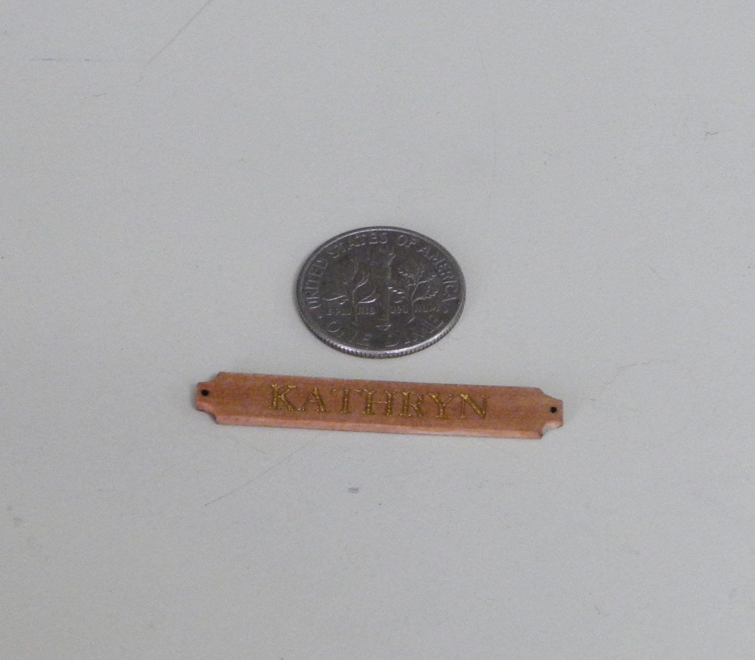
The name plates were drawn in CAD and then brought to a local trophy shop for laser etching onto some thin madrone. The operator put tape over the wood before the etching so that when the letters were painted the tape would mask outside of the letters to prevent smearing the wood. He also cut the outline completely through so that the pieces were fully separated. He also burned the mounting holes completely through.
The following photo shows one of the pieces that were created. The laser operator produced many more of the name plates than I needed, which gave me the opportunity to practice on them.
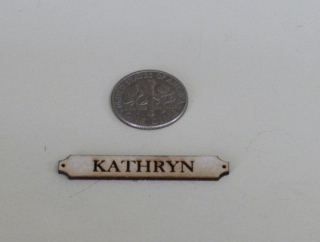
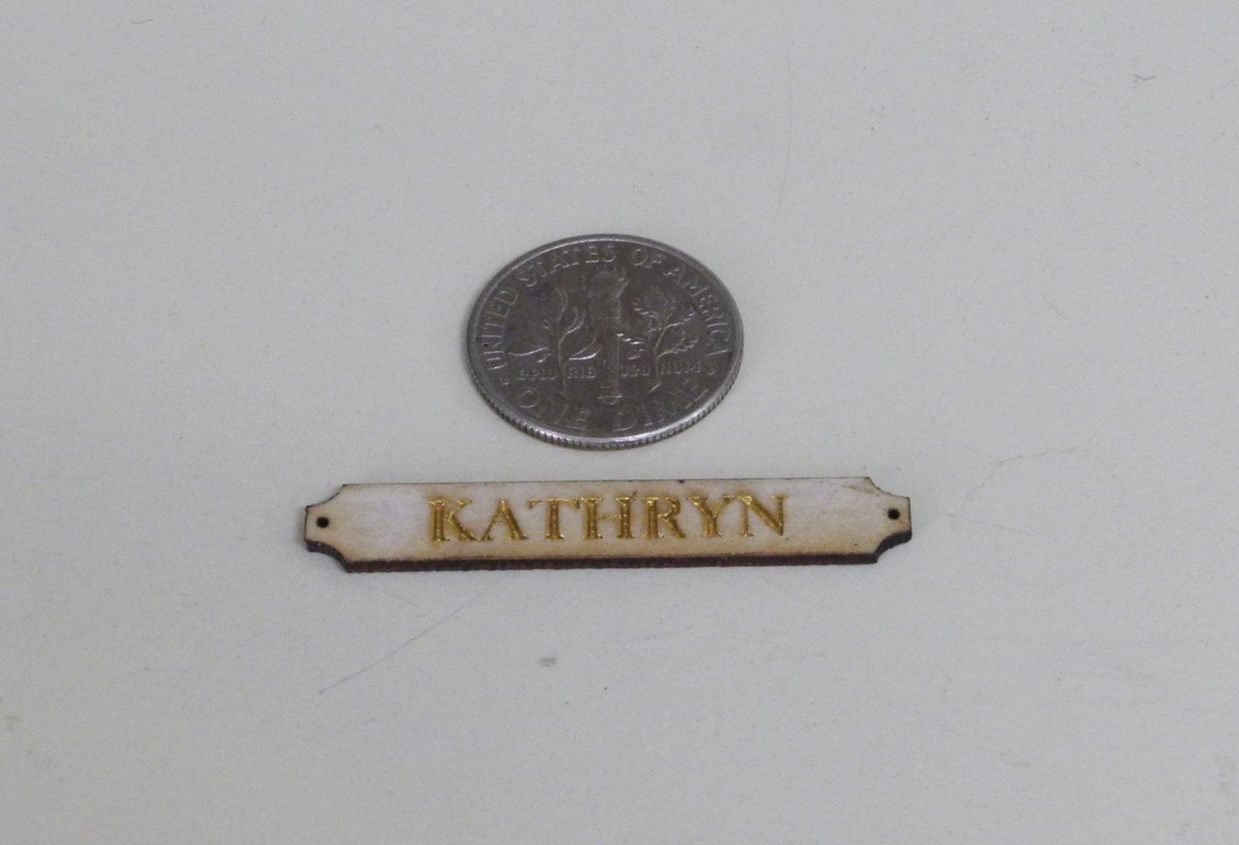
After sanding off the laser char, a thinned gold paint was used to paint in the letters. Painting required three coats to arrive at a good cover and depth of paint. The following photo is of a test piece that had not been cleaned of the laser char.
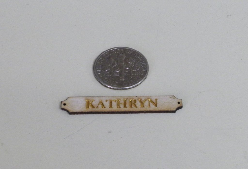
The tape was then removed. Some of the very small pieces of tape (within the enclosed part of the ‘A’ or the ‘R’, for example) needed to be carefully removed with the tip of a hobby knife.

A coat of wipe-on poly was applied to darken the bare wood, and then brass rods were inserted into the mounting holes to simulate bolts.
The name plates were mounted on the bow and on the rear quarter of each side of the model.
Working on these name plates convinced me that I would not be able to paint the trailboards, whether or not they were laser etched. The trailboards have no bare wood, so there will be many borders where two colors need to be neatly painted. Even if I was confident in my ability to pull that off, it would take quite a while to do it, the laser etching would be fairly expensive, and the trailboards would wind up being hidden behind the Jack Stay chains that will run outside them.
My approach for the trailboards will be to create them in CAD and then to bring them to a shop that does color laser printing. I hope to have them printed on card stock, and then glue them to boards that have been shaped to take them. Hopefully we’ll be able to get that completed in the near future, since work on the bow cannot proceed until the trailboards are in place.
Thanks everyone!
-
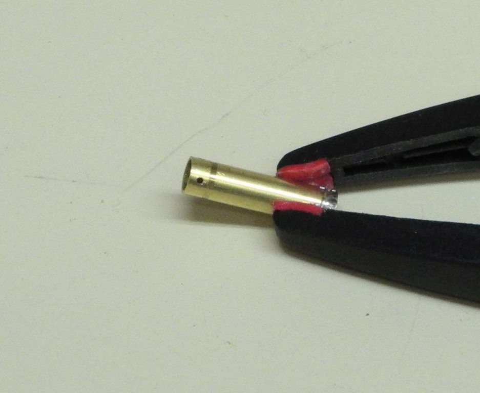
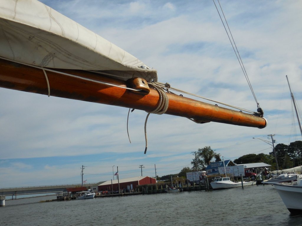
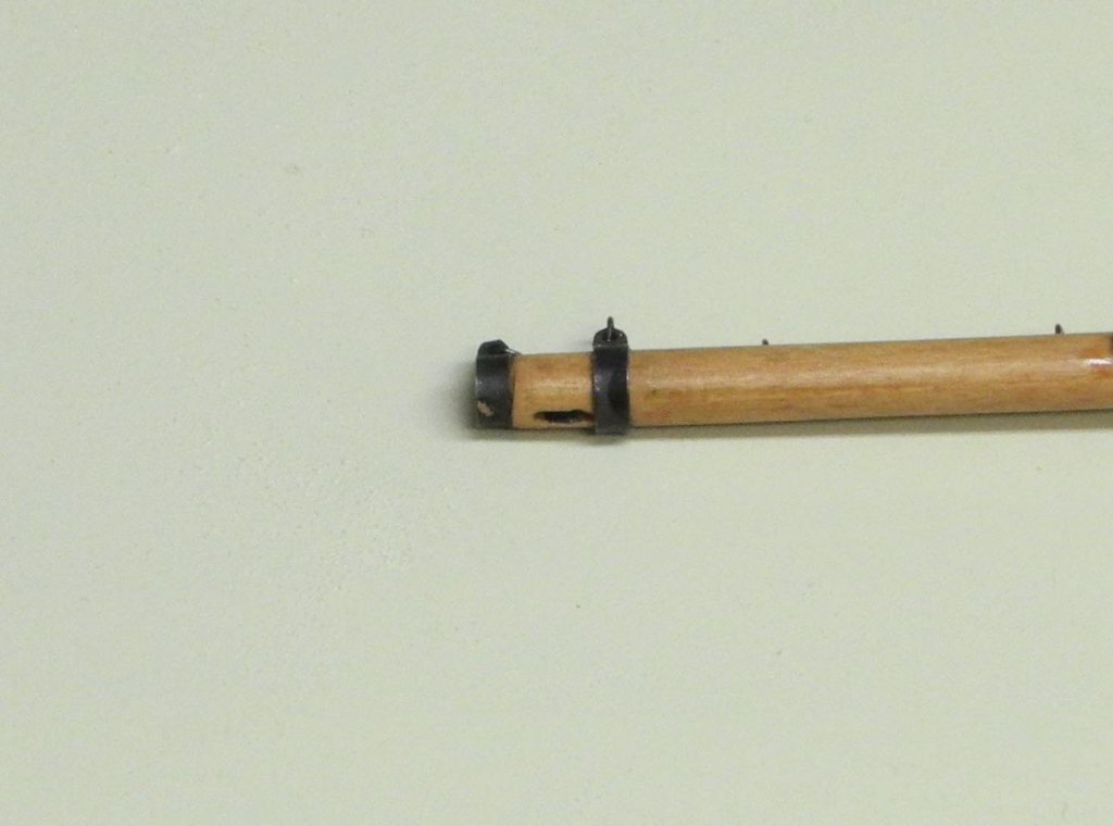
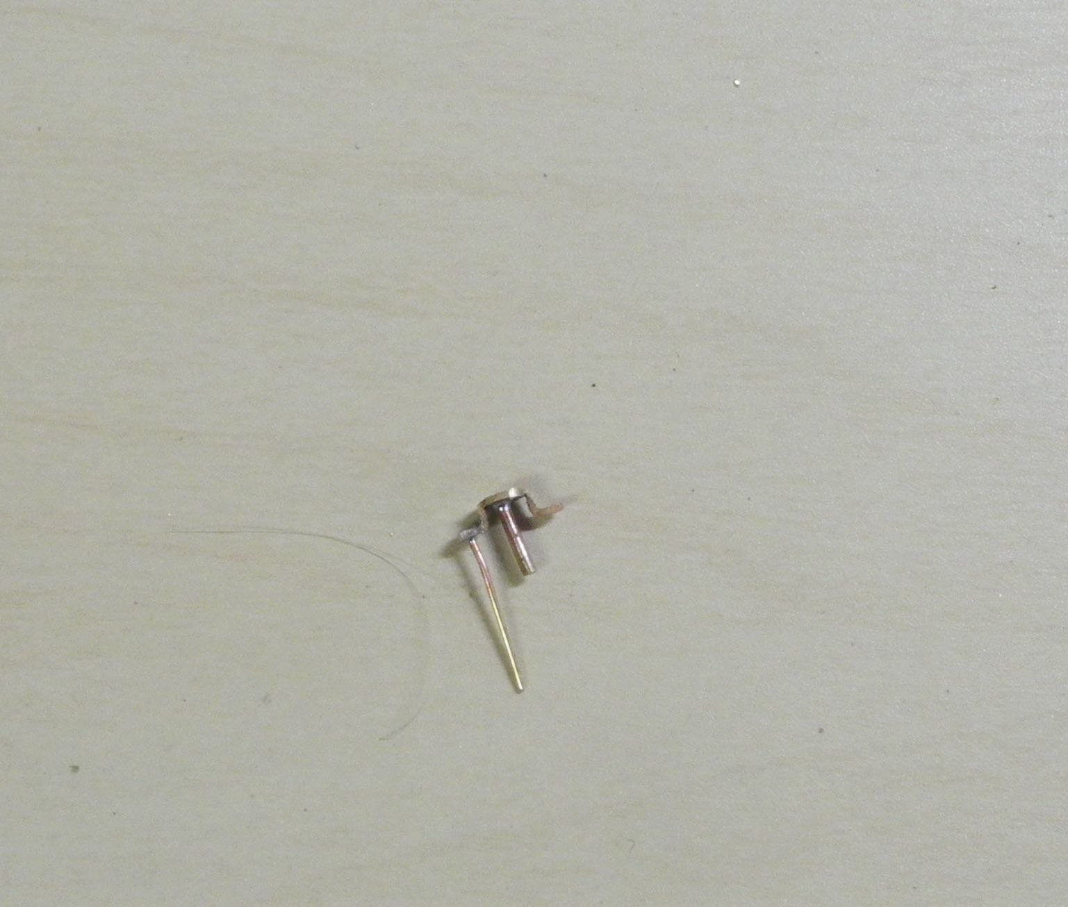
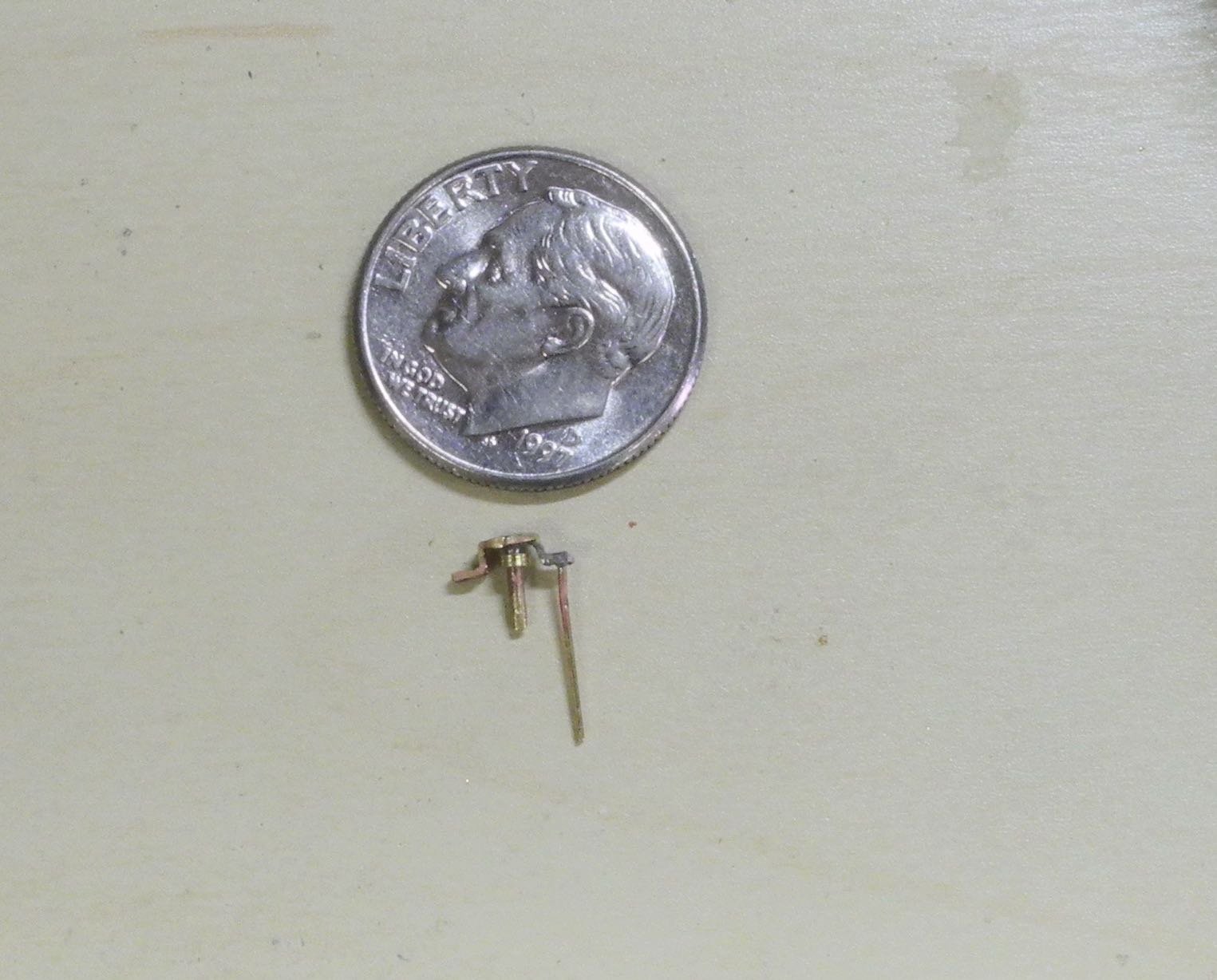
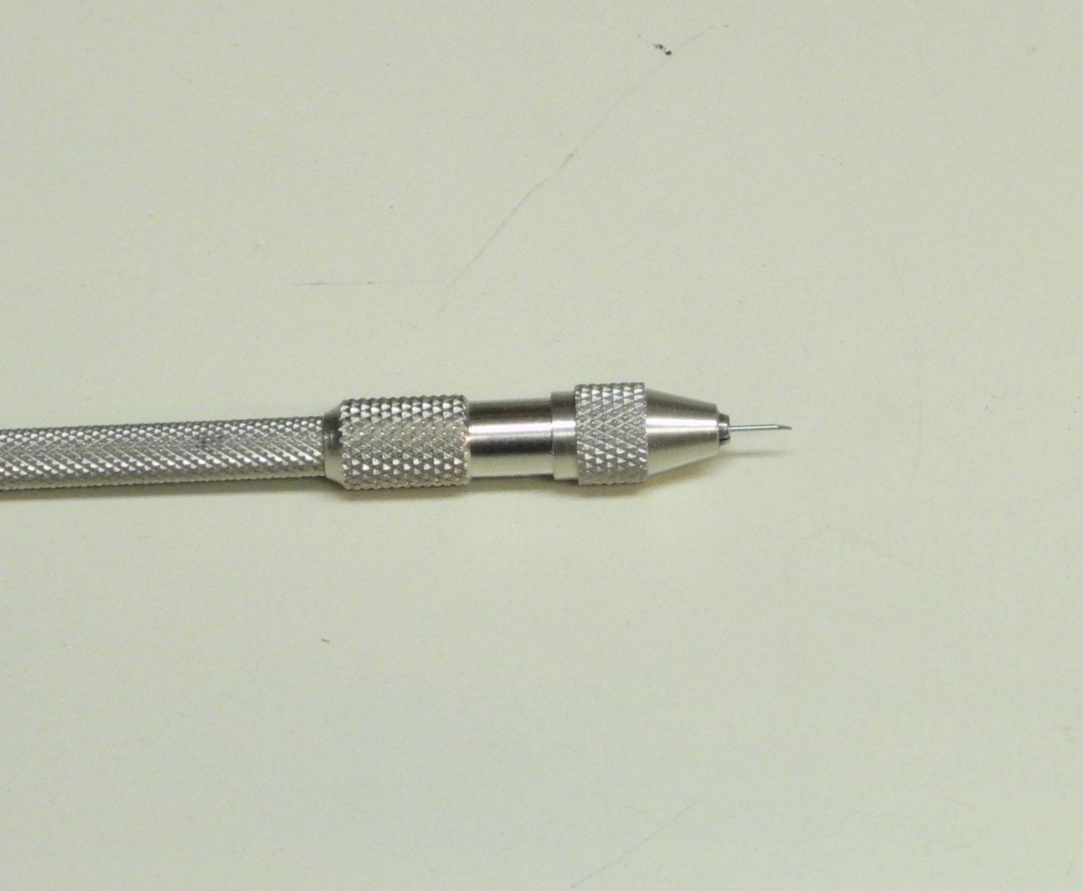
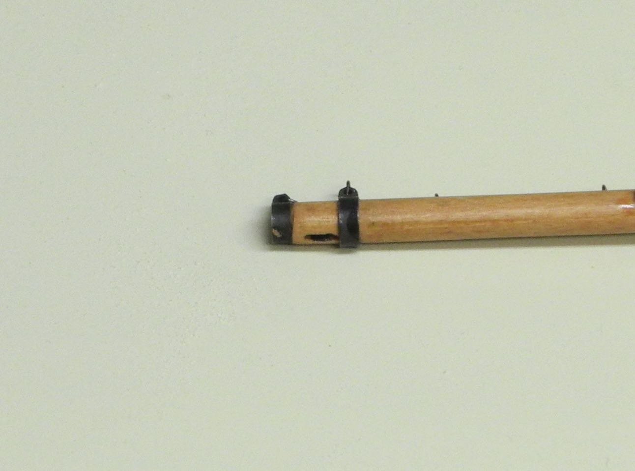
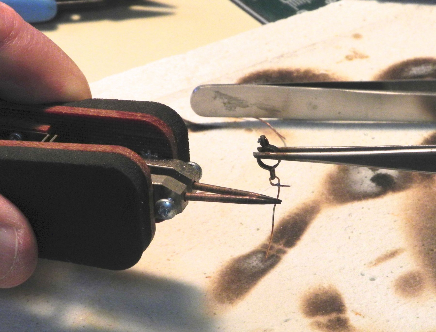
Part 70 –Bowsprit Cheek Block
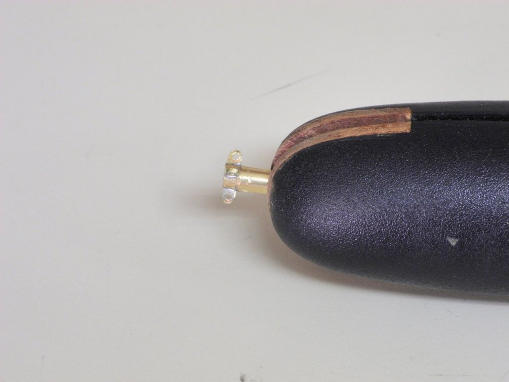
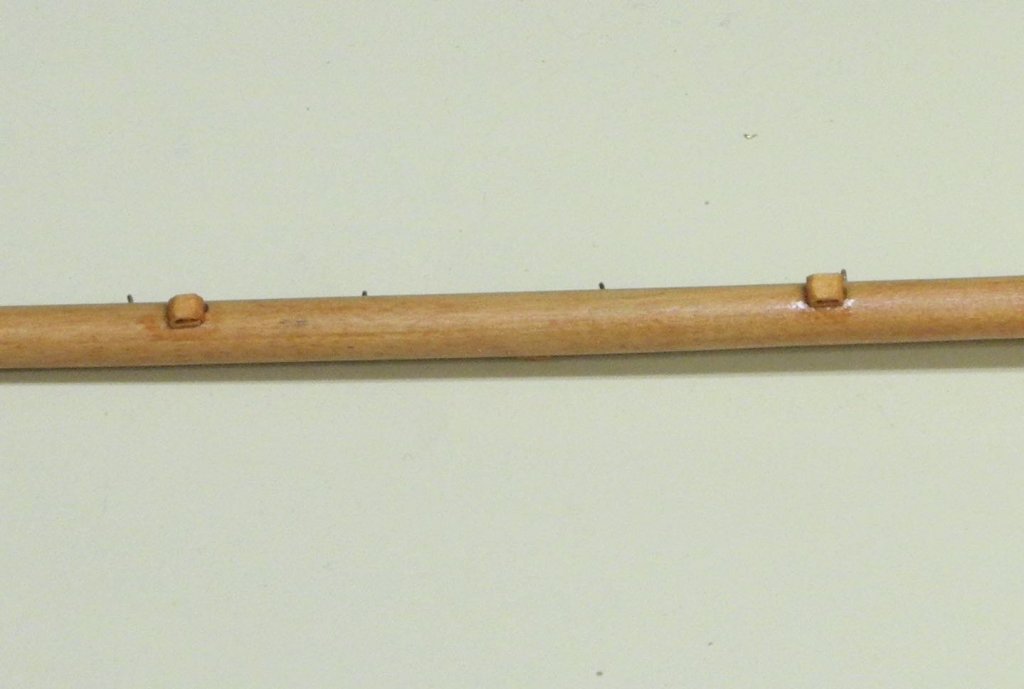
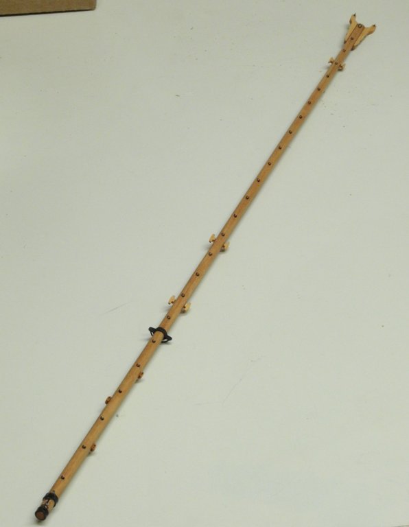
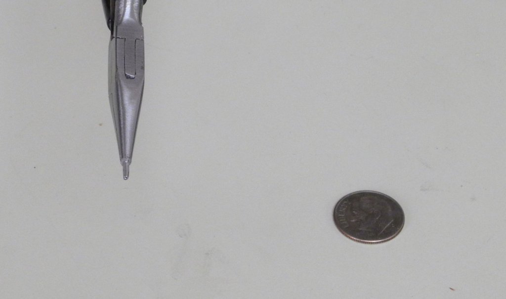
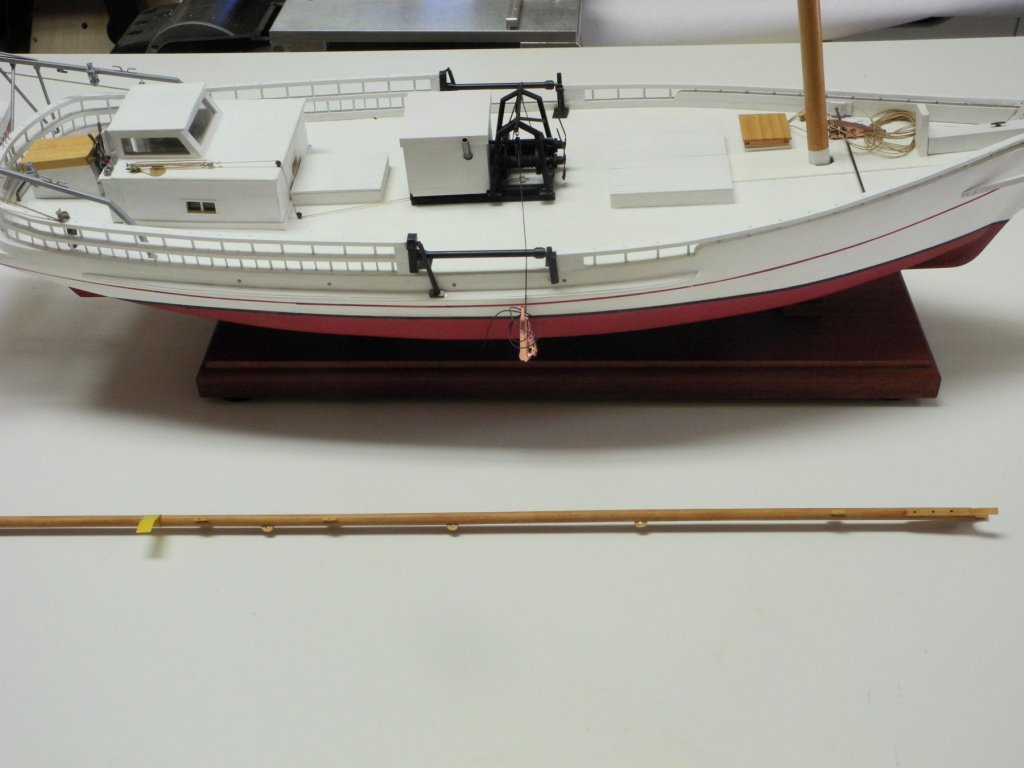
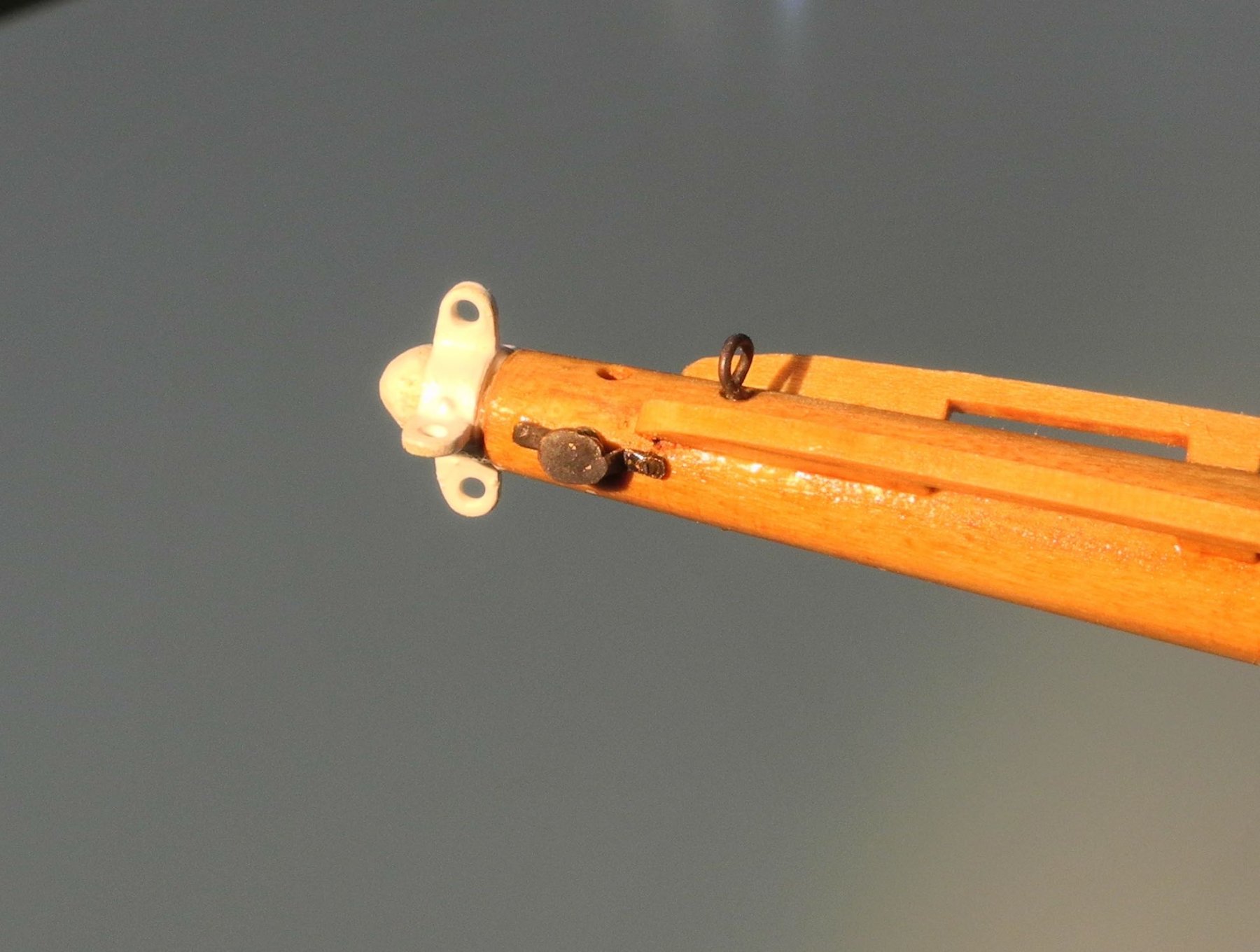
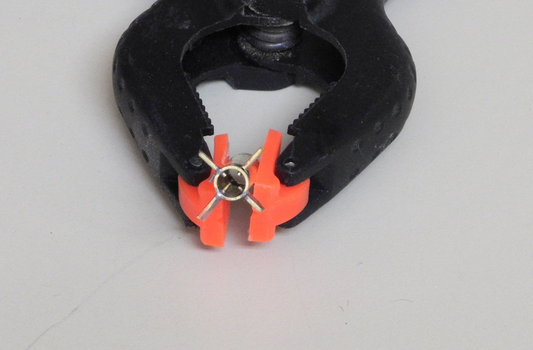
The Jib Downhaul runs through a Cheek Block located on the port side of the bowsprit, immediately behind the Bowsprit Band as seen in the following photo (just aft of the fishing weight
 ).
).
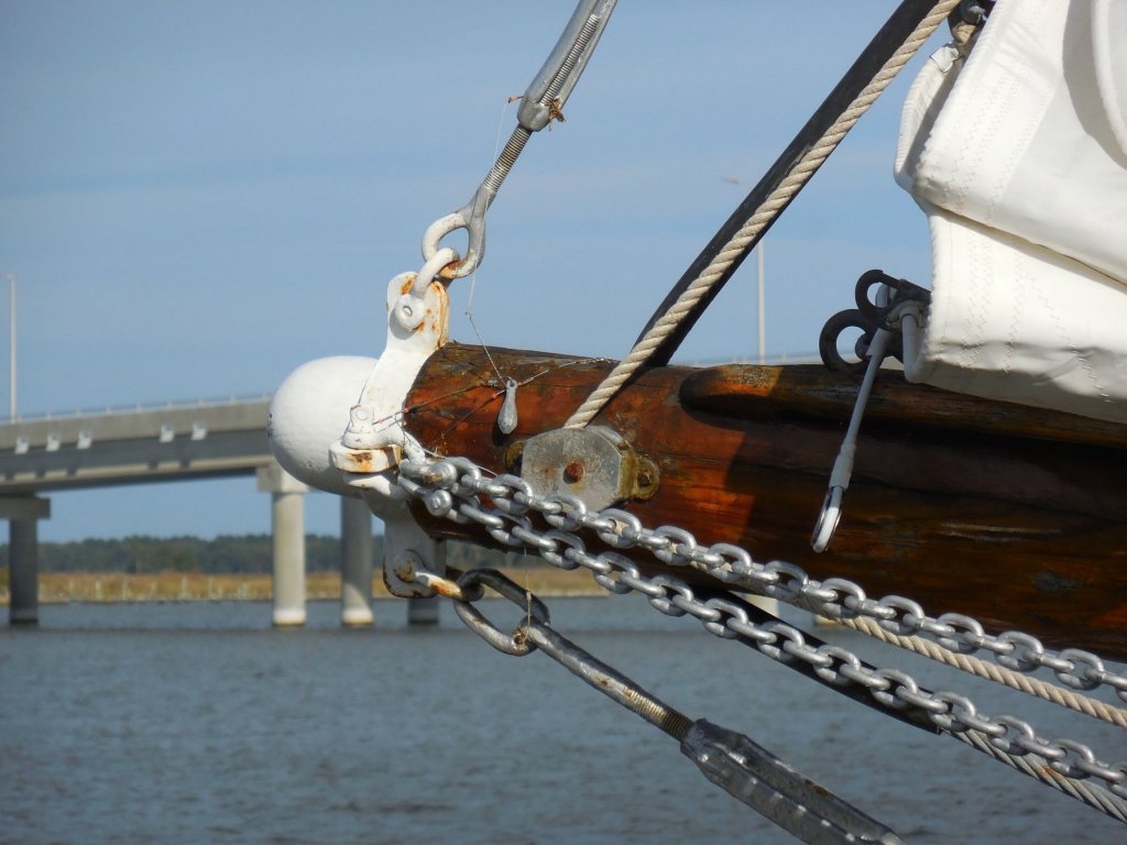
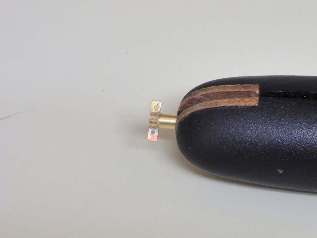
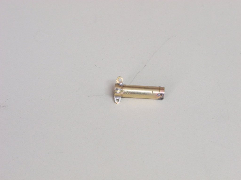
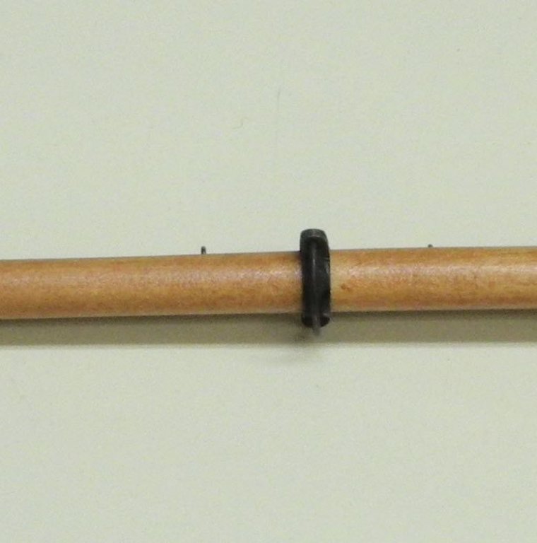
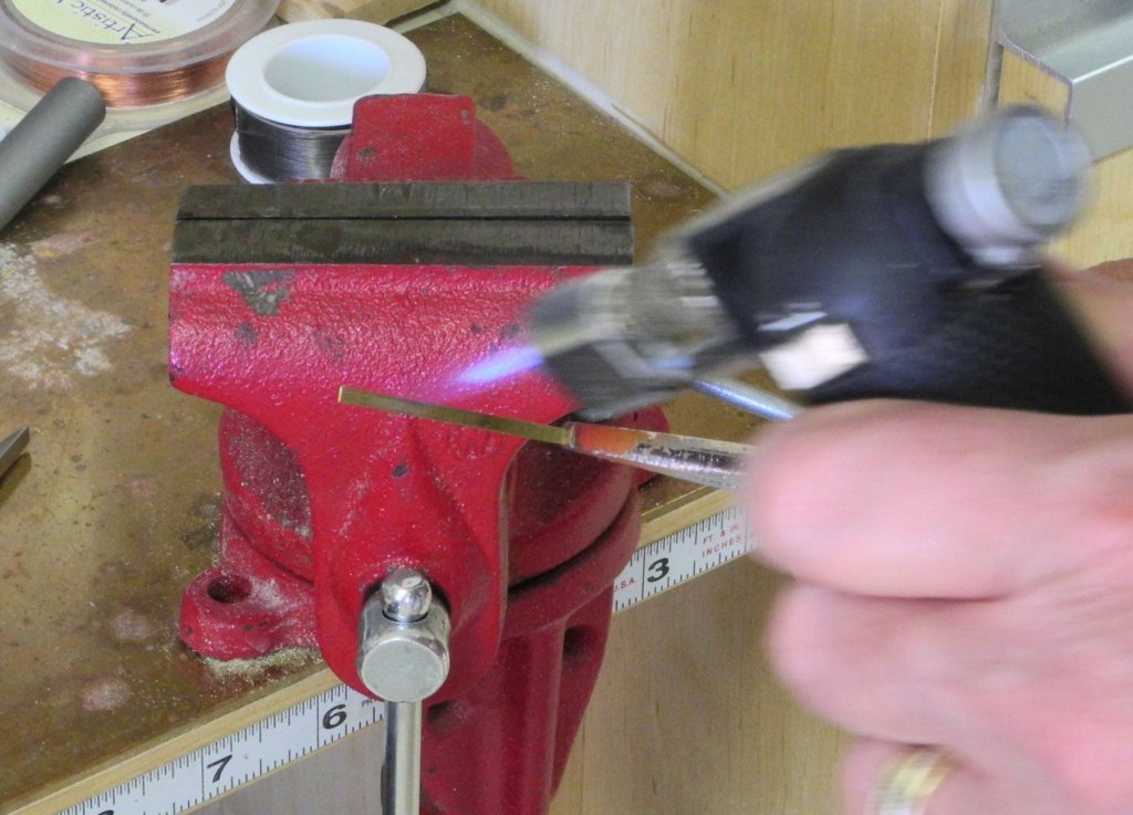
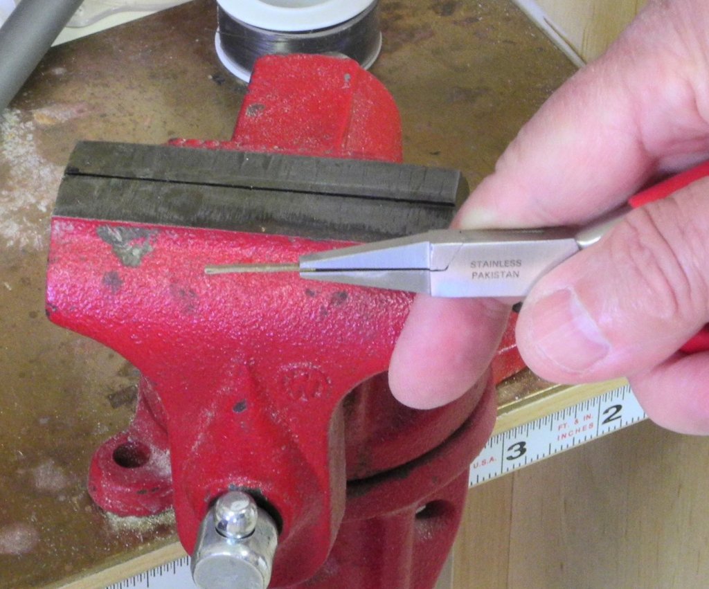
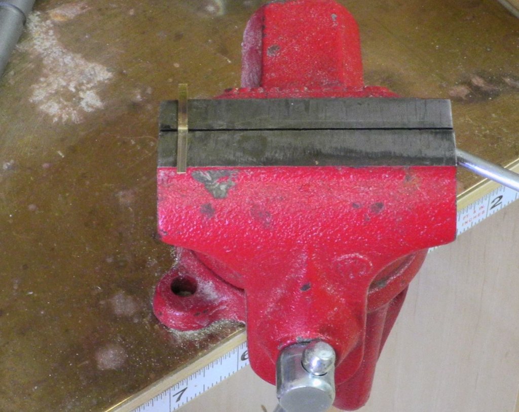
The housing for the block was made from 3/32” x .020” brass strip. It was first filed to a square shape.
The square housing was filed to a round shape, then the strip was annealed. After annealing, holes were drilled for the shaft that would hold the sheave, and for mounting posts on each side of the housing. The housing was then bent to shape.
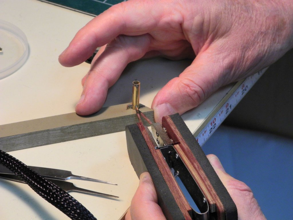
The shaft for the sheave and one of the mounting posts were soldered to the housing.
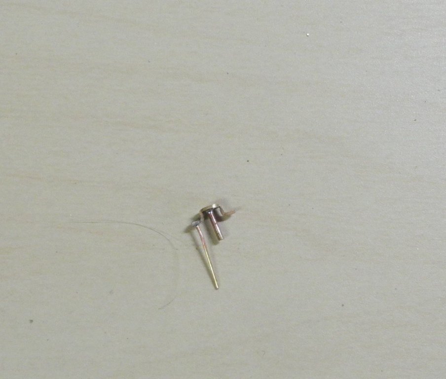
The sheave was made from a 1/16” brass rod, center drilled to take the 1/32” shaft, and then parted off to be .030” thick. The sheave was placed on the shaft without any glue or solder. The side of the bowsprit will hold it in place.
A hole for the forward mounting post was drilled in the bowsprit. After blackening, the Cheek Block was mounted on the bowsprit by gluing the forward mounting post to the bowsprit. Another hole was drilled in the bowsprit through the aft mounting hole, and a mounting shaft was glued through that hole into the bowsprit. A ringbolt was also mounted on the top of the bowsprit just aft of the Cheek Block. This ringbolt will secure the clew of the jib.
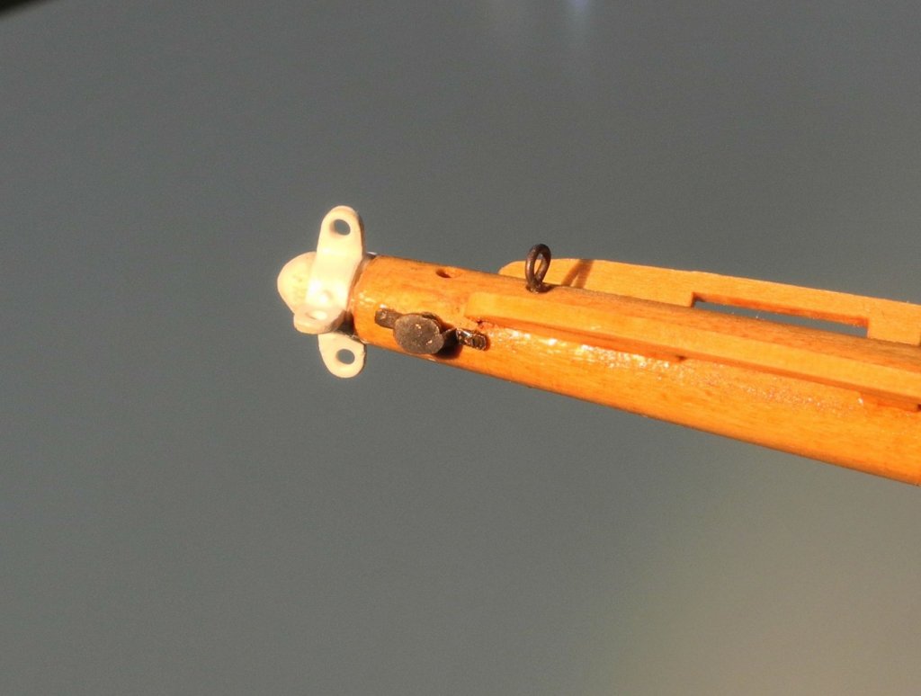
The hole seen between the Bowsprit Band and the ringbolt mentioned above is for the Jib Stay, which passes through the bowsprit and is secured to the outer stem.
Thanks everyone for the ‘Likes’ and comments.
-
11 hours ago, mtaylor said:
Frank,
They could be etched and then the etching filled in with paint. Might make the painting less daunting.
Hi Mark. That's one of the alternatives I've been considering, but I'm still concerned about the painting.

-
9 hours ago, John Allen said:
Frank,
Keeps getting better!
Thanks John. I'm happy with the progress - getting closer to the start of rigging.
8 hours ago, Thistle17 said:Only additional comment I would make at this point is that your work product is museum quality in my opinion!
In regard to trailboards. If you are considering relief carving I would suggest laser etching. I witnessed a very convincing demonstration of laser etch, at reduced power, that inscribed a beautiful stern banner on a model part. A drawing was scanned into Corel Draw and converted to a laser file that was compatible with the unit. Just a thought.
Joe
Thanks Joe. I've been looking into laser etching the trailboards, but the carving isn't the real issue. The painting is pretty complex, and I'm not confident I can pull it off at 3/8" scale. I did get some laser etching done on the name plates attached on each side at the railings. I'll be posting some pics of that once I get them onto Kathryn.
-
9 hours ago, GeraldTodd said:
Are you putting on the fishing weight?
")
Ha-ha - no, Jerry - I don't think so. I didn't notice the weight at the time I took the photo, so I don't know the story behind it.
-
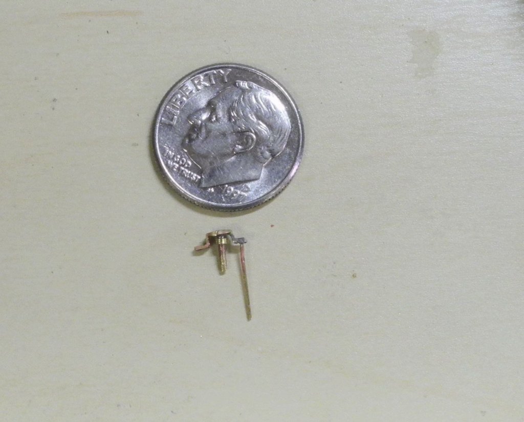
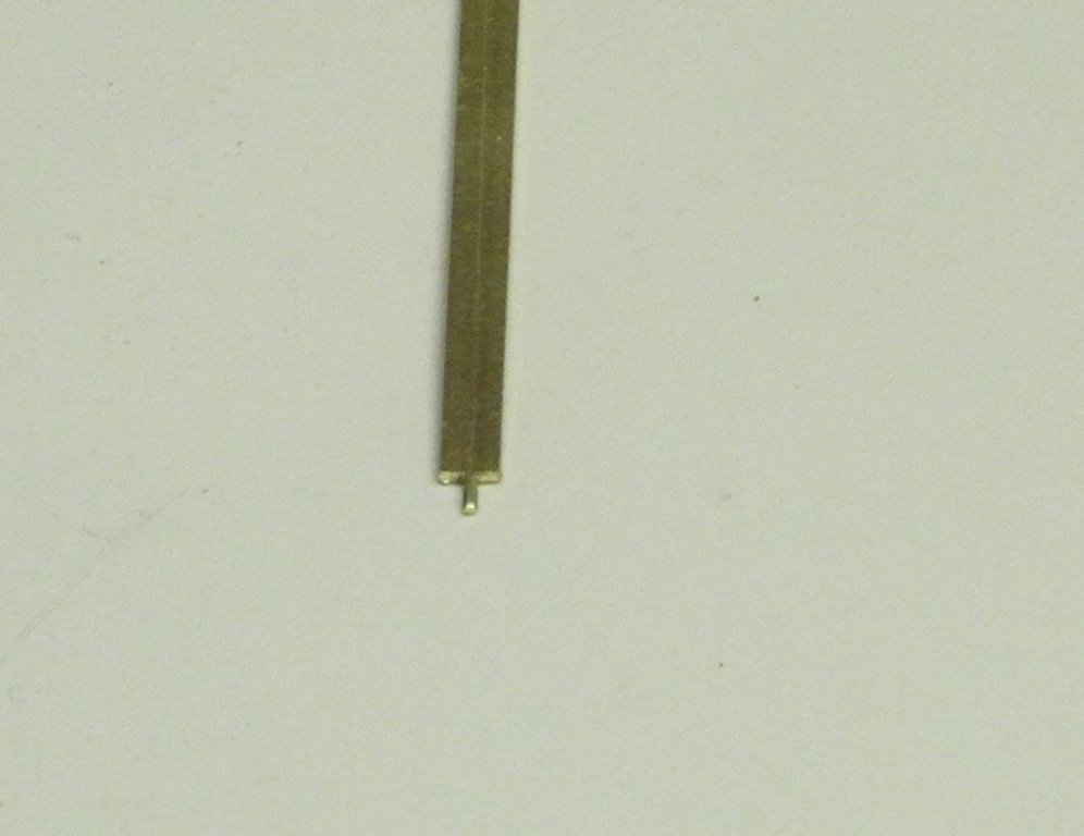
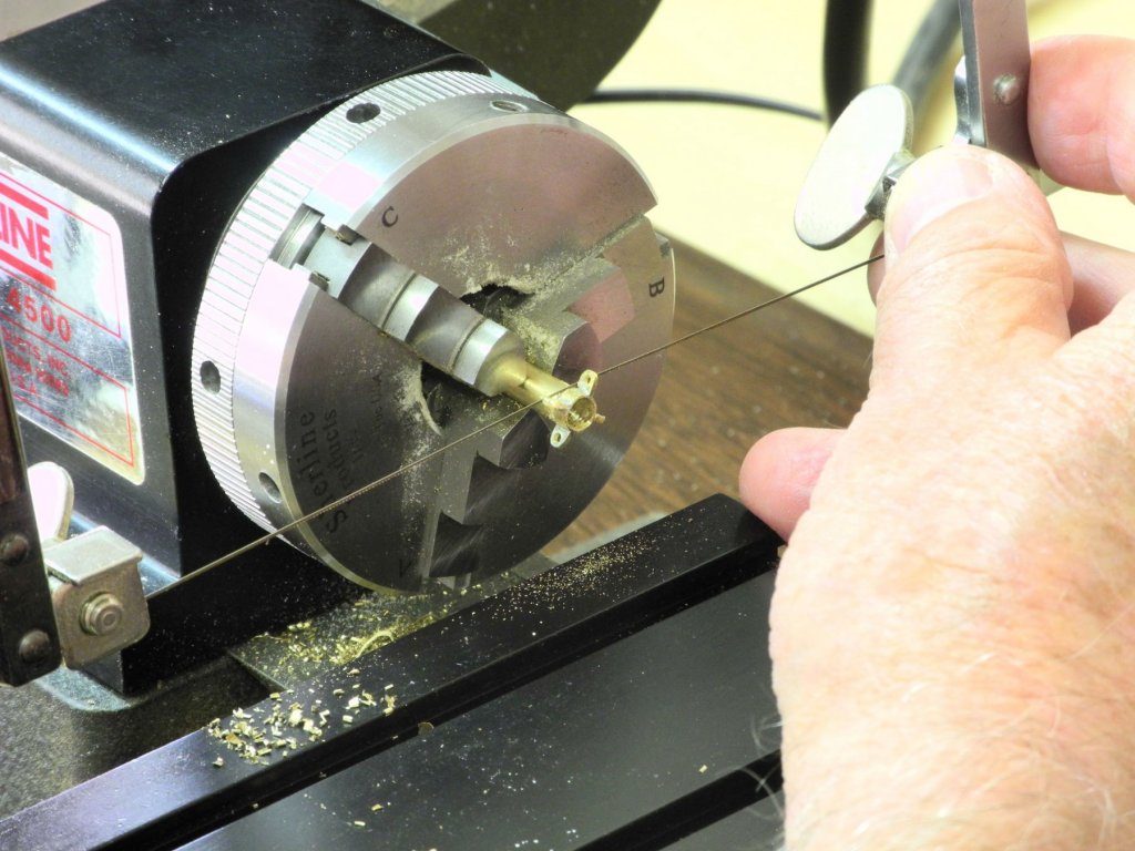
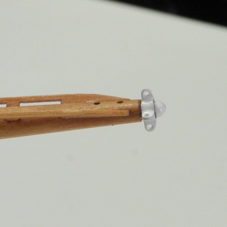
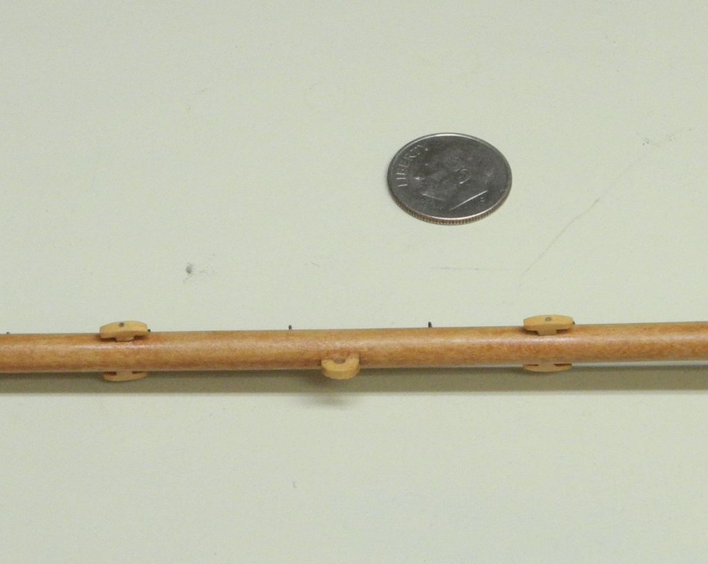
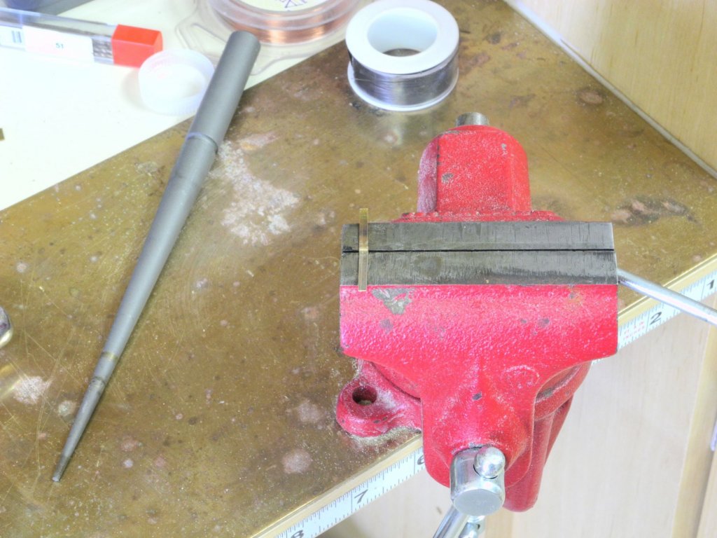
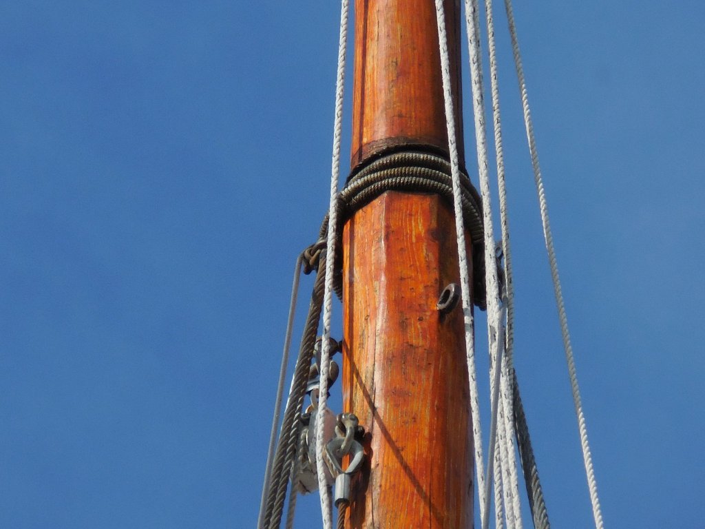
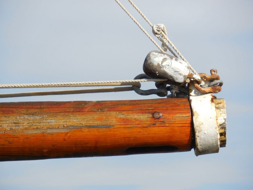
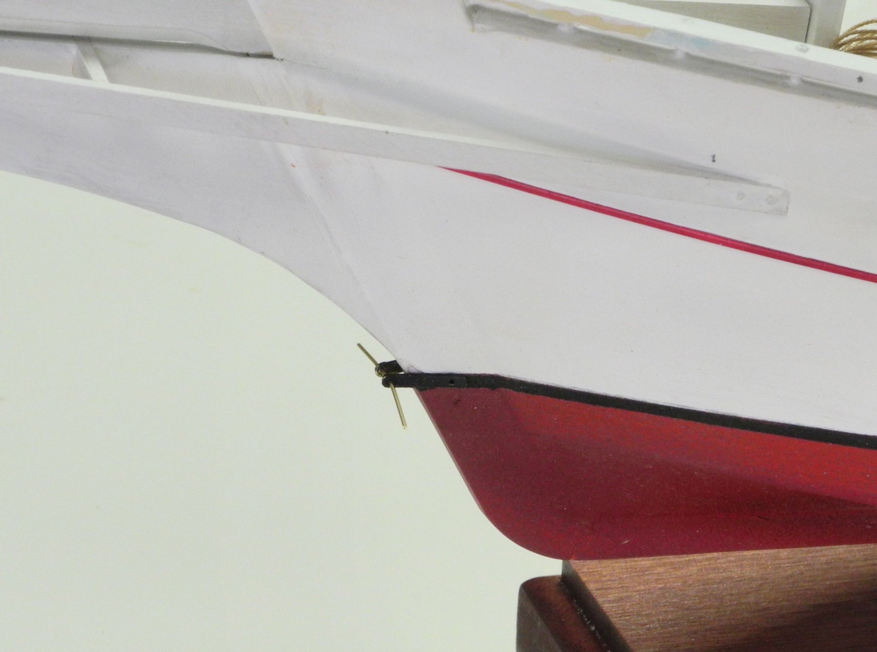
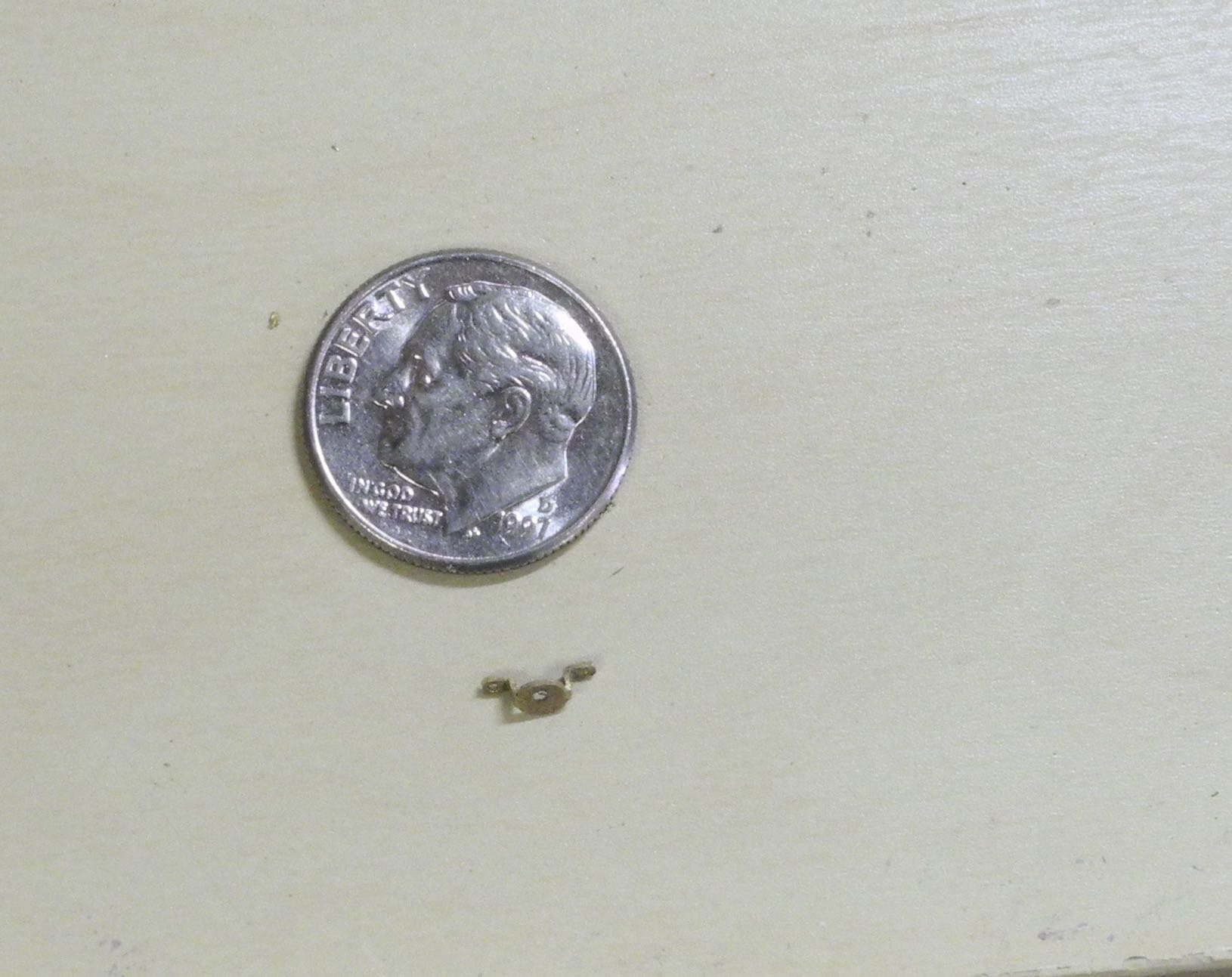
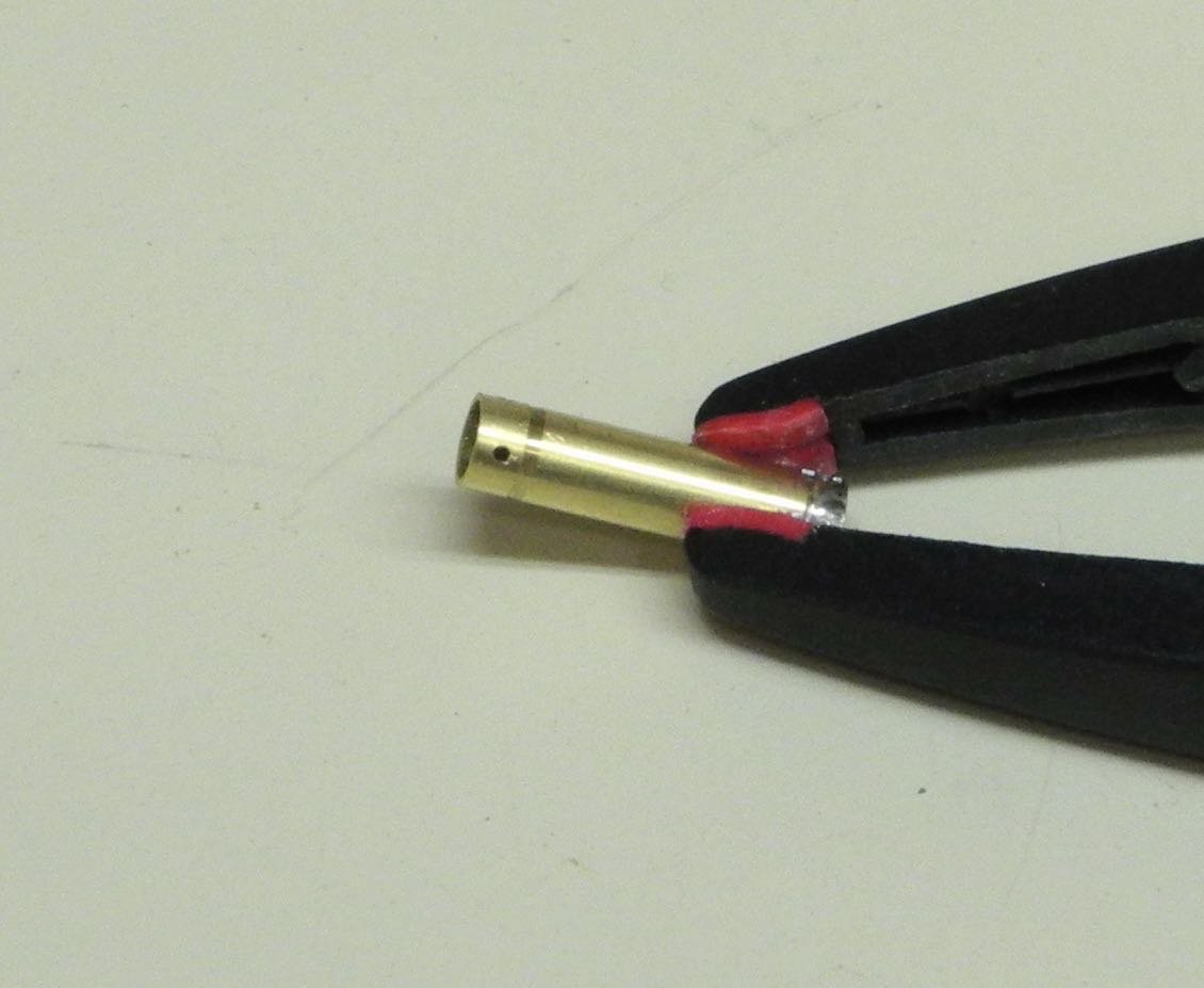
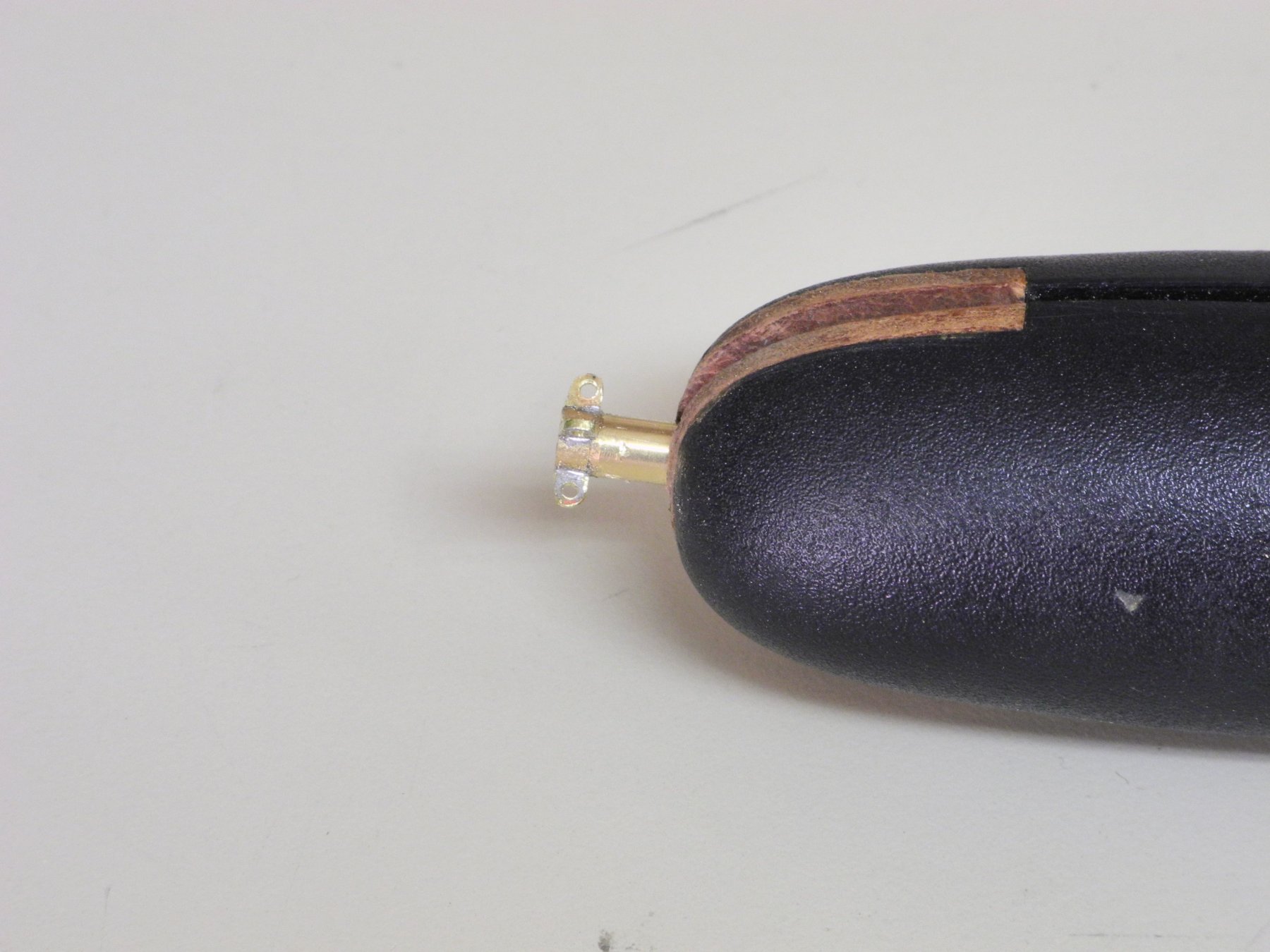
Part 69 –Bowsprit Iron
In Part 67, iron rings for the boom and mast top were made by bending annealed brass strips to form the tabs and the shape of the ring itself. This approach worked well for irons that have 1 or 2 tabs. However, Kathryn’s Bowsprit Iron has 4 tabs as shown in the following photo, so a different method was required.

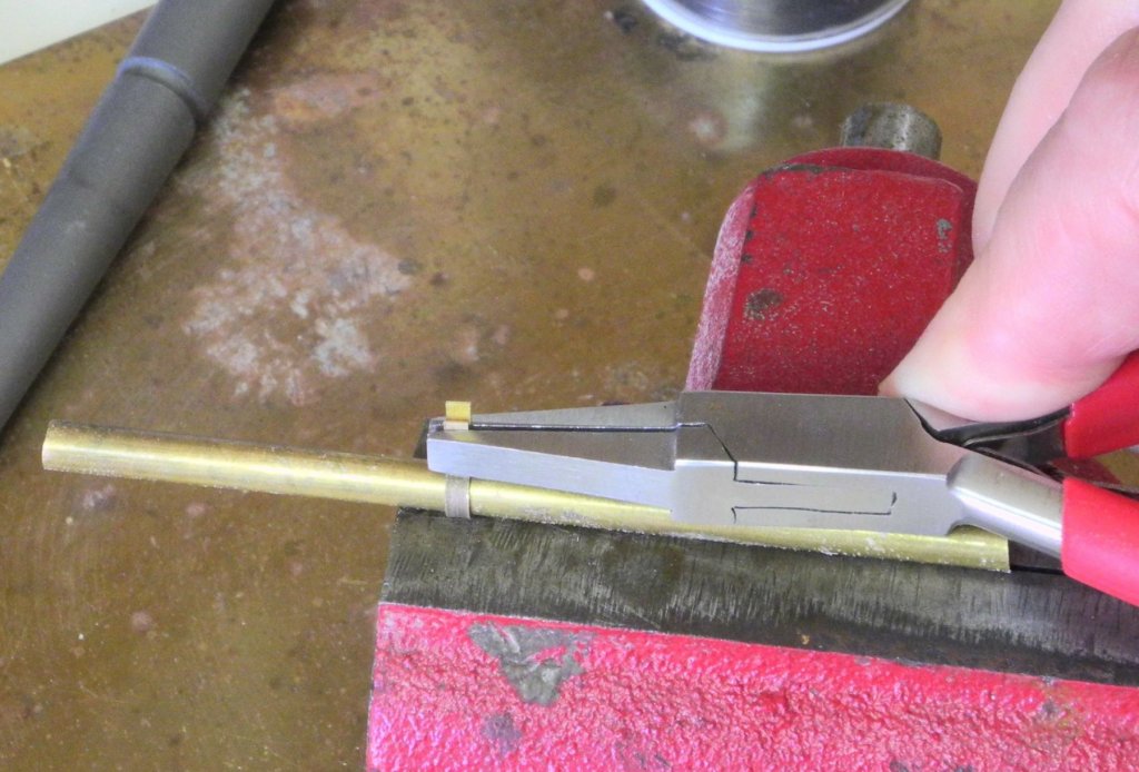
A brass tube that would fit over the forward part of the bowsprit, along with 1/8” x .025” brass strips for the tabs were used.
The end of the strip was formed into a small peg, using the rotary tool and files. The peg was sized to fit into four holes drilled into the brass tube.
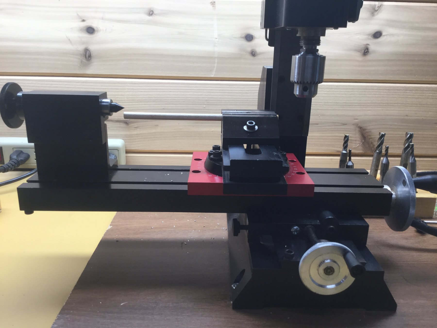
The holes were aligned using an index block in the milling table, and drilling was performed on the milling machine.
A jig was made from Corian with a hole for holding the tube and with slots at right angles to keep the tabs properly aligned while soldering the tabs to the tube.

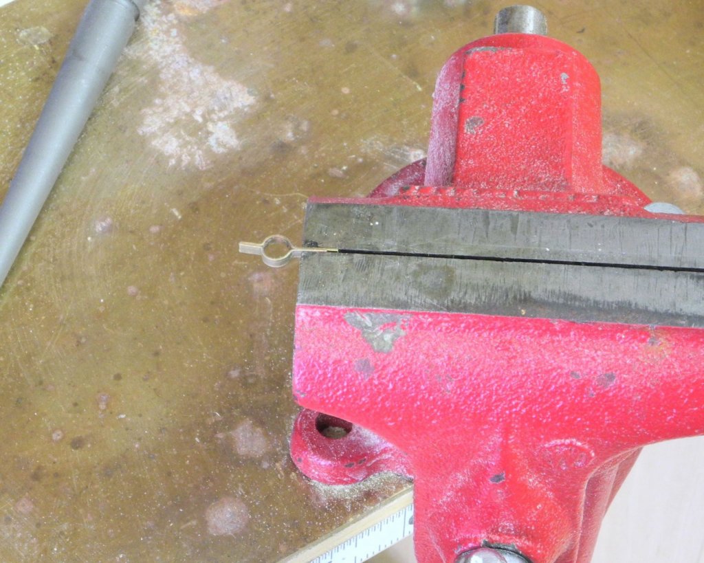
The tabs were then drilled. The drilling was performed using a series of drills starting with a #72 and progressing to a #53.
After the drilling, the tabs were roughly ground and filed to the rough finished shape.
The configuration was held in the three-jaw chuck on the lathe, and the ring was parted off using a jewelers saw. For this work the lathe remained turned off, and the chuck was simply turned by hand.
The shape of the Bowsprit Iron and tabs was finalized by filing, and the iron was then cleaned up and polished.
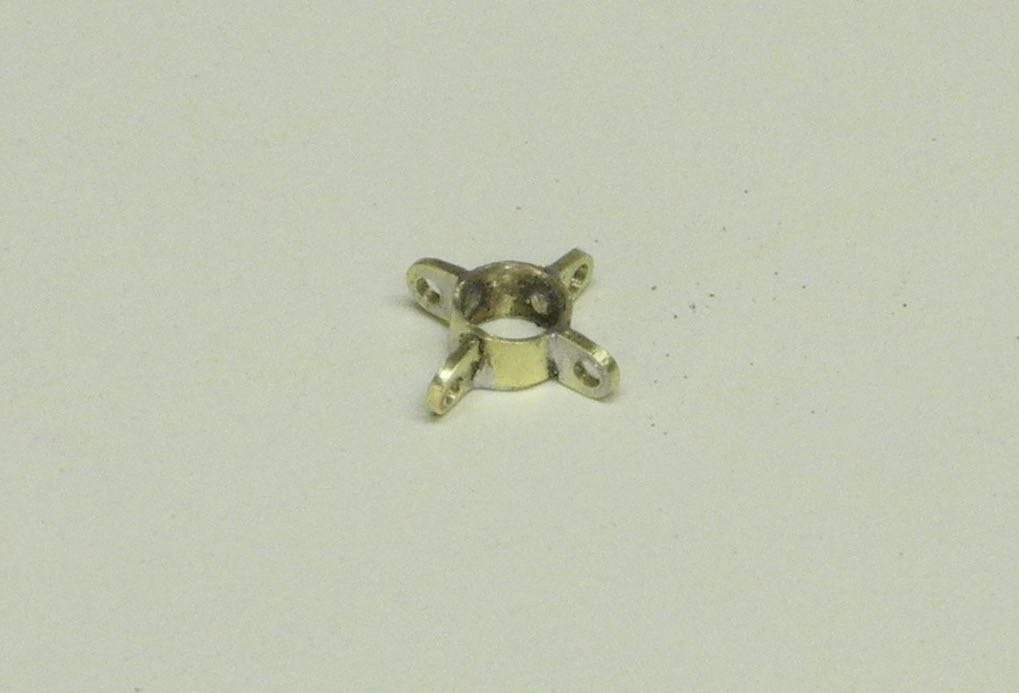
The Bowsprit Iron was painted white and was CA glued to the bowsprit. The forward end of the bowsprit was also painted white.
Before the bowsprit can be permanently mounted on the model, the Trailboards need to be created and mounted. This is a subject I’ve been working on and thinking about for some time, but I still haven’t determined the best way to create the Trailboards. I’ll keep thinking about it while I do other work required for the model’s rigging.
Cheers, everyone!
- PeteB, thibaultron, druxey and 14 others
-
17
-
-
Thanks, Ron. I'm pleased with the way Kathryn is coming together.
-
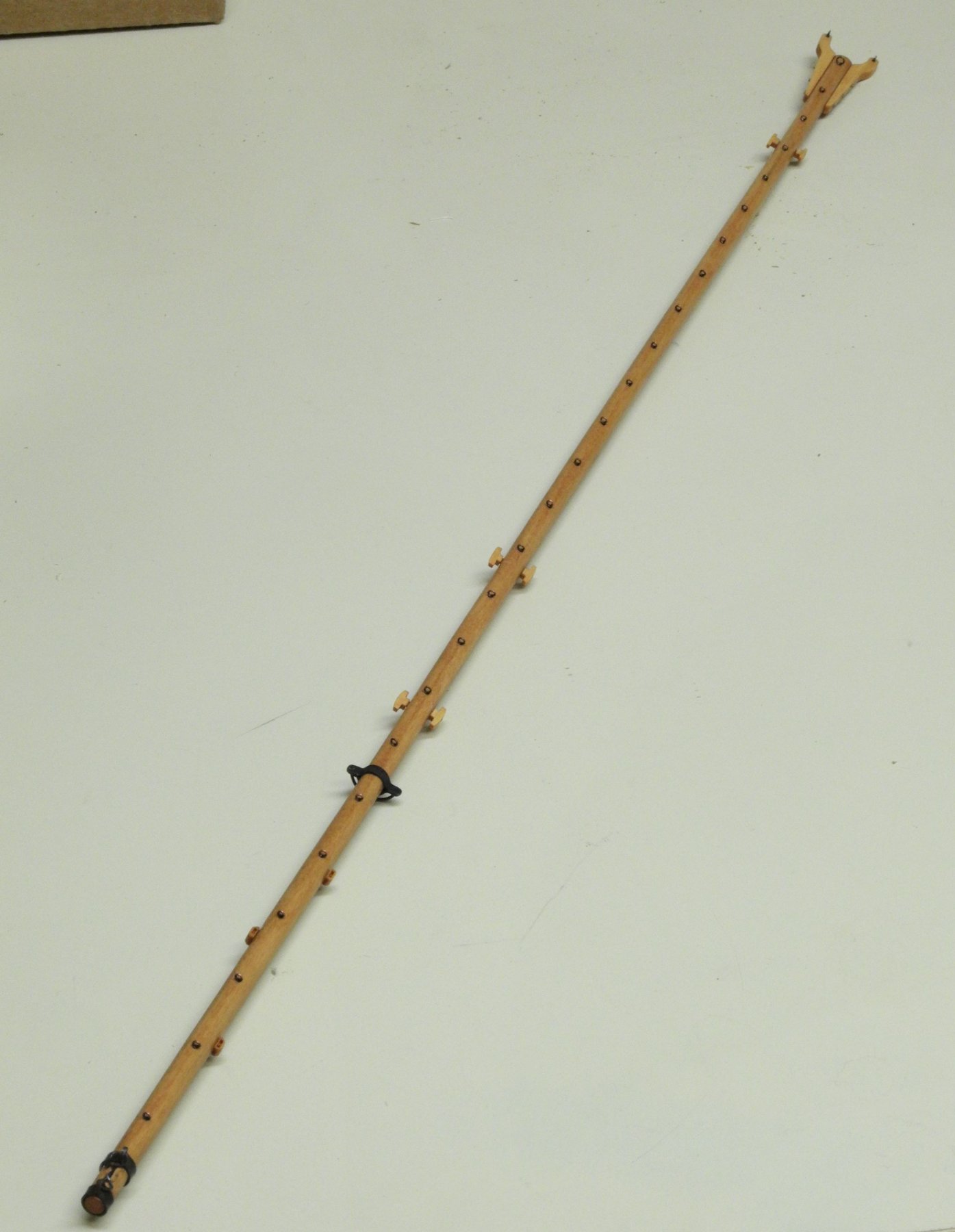
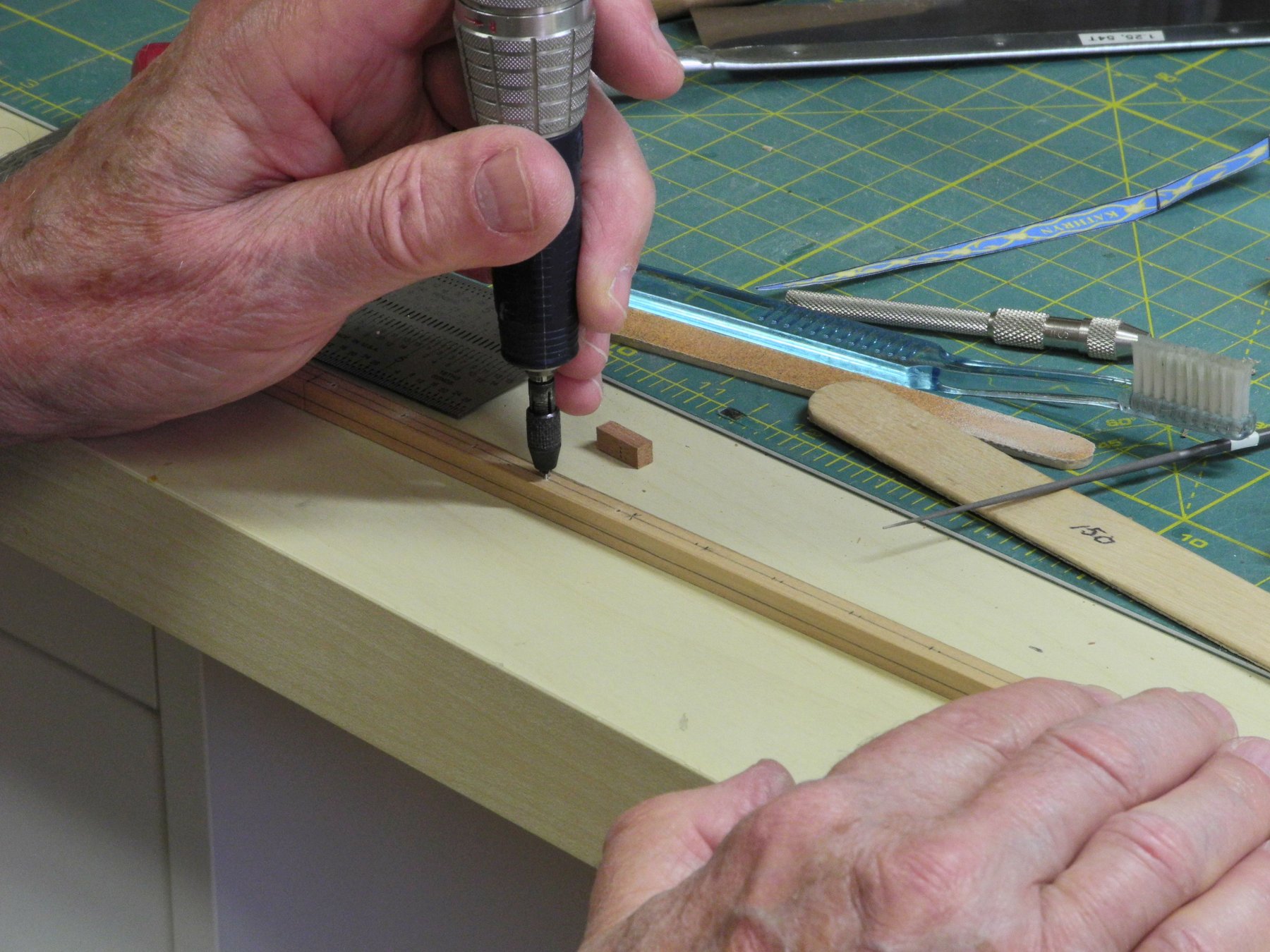
Part 68 –Boom Cont’d
The last components that needed to be made for the boom are three Reefing Blocks. These are positioned aft of the boom Iron and bail, so they needed to be left to last.
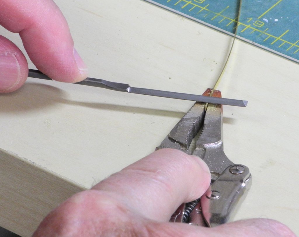
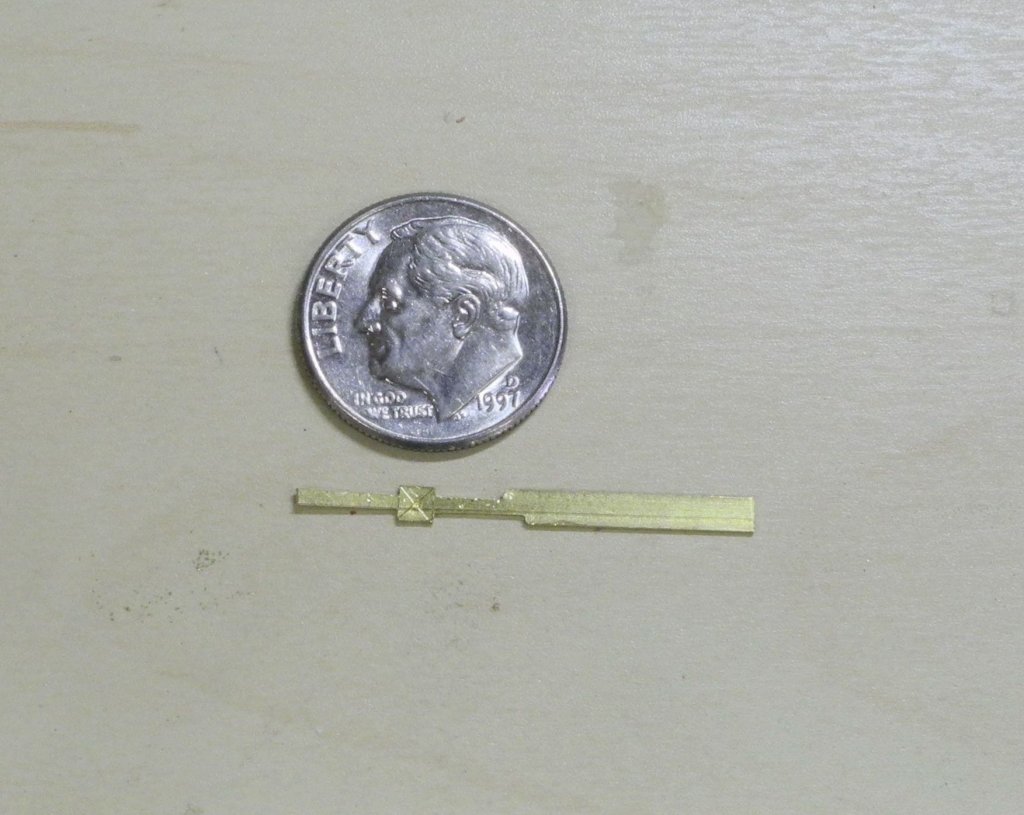
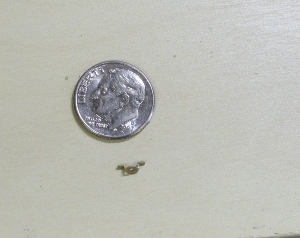
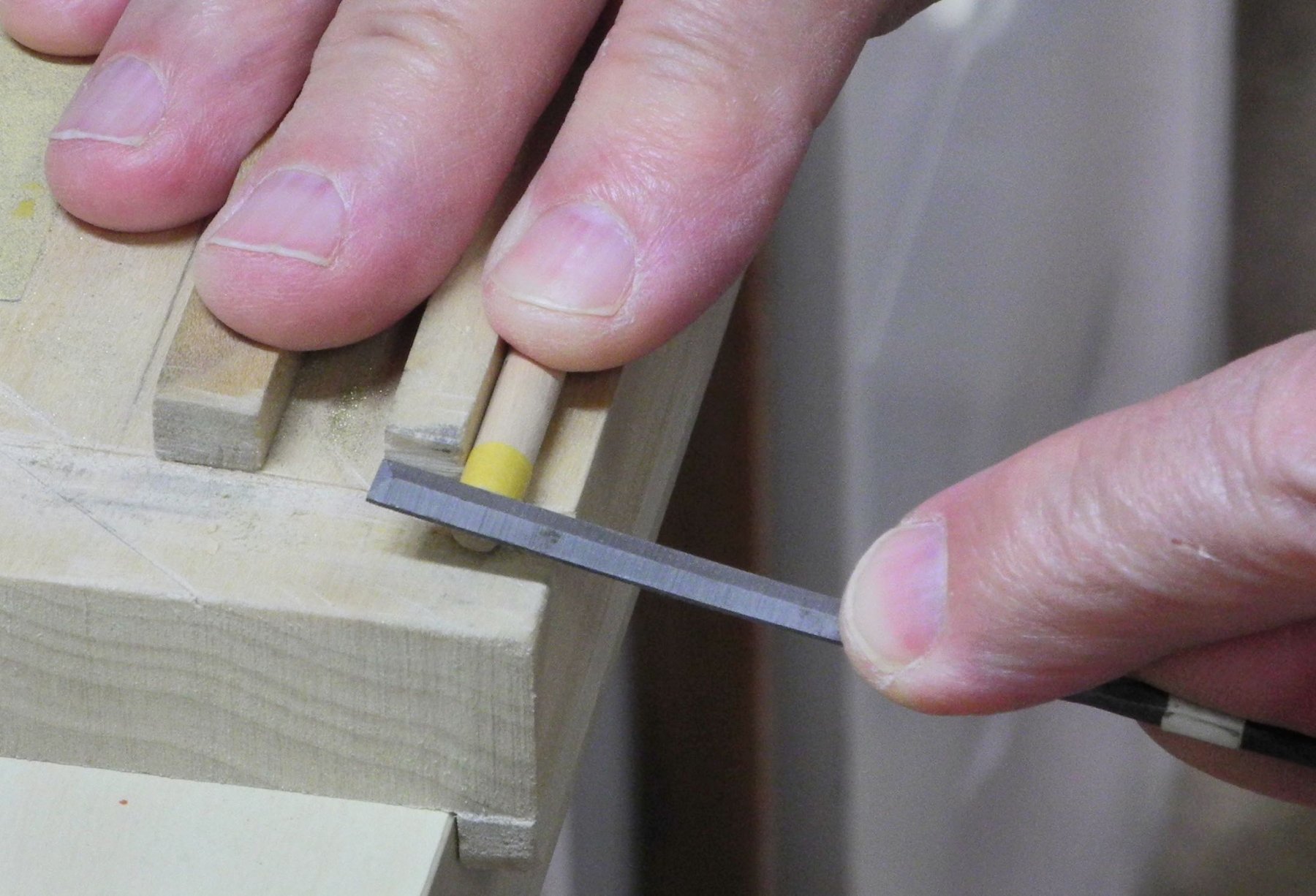
The Reefing Blocks were made from 1/8” x 1/16” stock. Two holes were drilled for each block, to simulate the sheave.
The sheave was shaped using a chisel that was made from a #76 drill – the back end of the drill was shaped and sharpened using a diamond cylinder in a rotary tool, and was held in a small pin vise while in use.
The stock was then thinned down further in the thickness sander. The side that would be attached to the boom was made as thin as possible (about half the diameter of the #76 drill, or .010”.
The blocks were separated from the stock and the forward and aft vertical edges were rounded.
After attaching the blocks to the boom, the boom is now completed.
There are many components to the boom. The following is a summary of those components:
At the aft end of the boom, there are two boom irons with an embedded sheave between them.
· The aftmost iron secures the fixed end of the Topping Lift.
· The embedded sheave is for the Topping lift to pass through on the way to the Topping Lift Cleat.
· The forwardmost of the two irons serves to secure the clew of the sail. The line from the clew runs to the Topping Lift Cleat.
Moving forward, the next components are the Reefing Blocks discussed earlier. There are two on the starboard side and one on the port side of the boom.
Forward of the Reefing Blocks is a boom iron with a bail. This is for securing the Main Sheet.
Next, there are two cleats on each side of the boom. On the starboard side these are both used to secure the Reefing Lines. On the port side, the aft cleat is for a Reefing Line, and the forward cleat is for securing the Topping Lift.
There are three fairleads under the boom for the Lazy Jacks, and a pair of cleats forward of these fairleads that serve as anchor points for the lazy jacks.
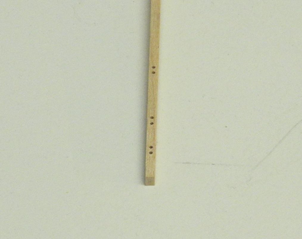
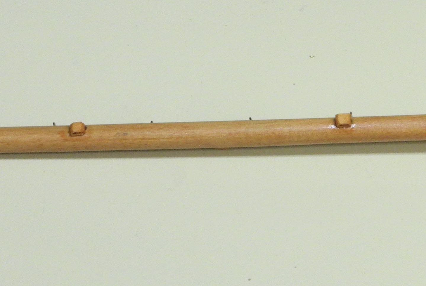
There are screw eyes located every 24” along the boom for the sail lacing, and a larger eyebolt is located at the very forward end of the boom to secure the boom lift and the tack of the sail.
The following photo shows the boom as completed.
Thanks, everyone!
-
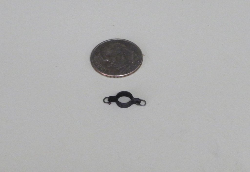
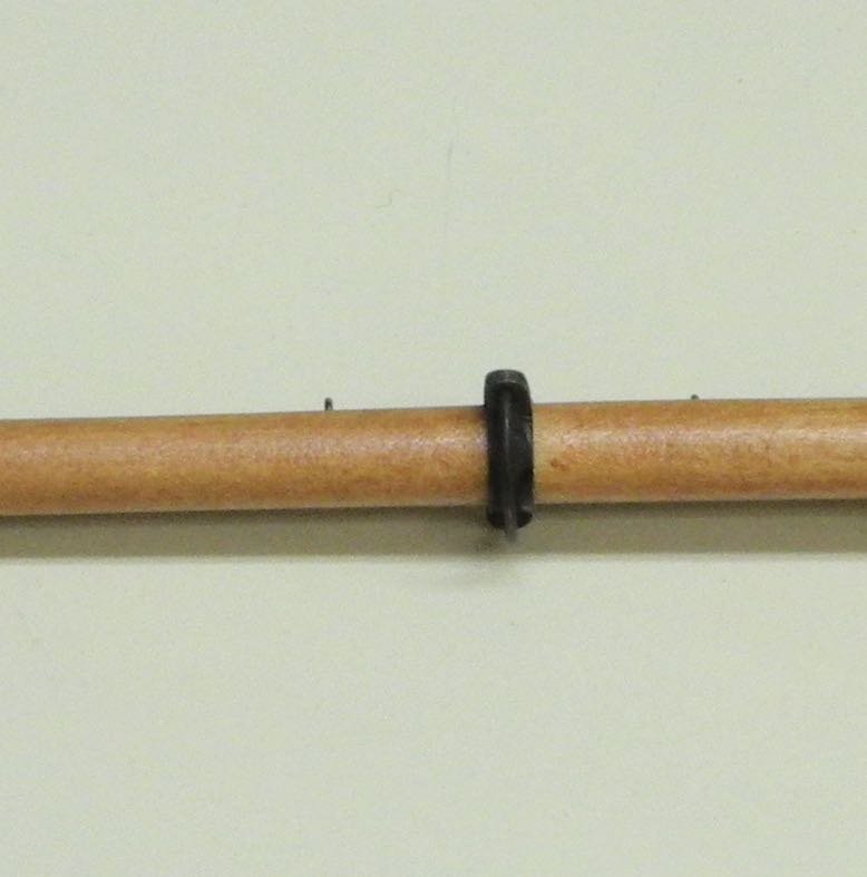
Part 67 –Boom Hardware
Kathryn’s boom has three rings that serve various rigging functions (these will be covered in detail when we get into the actual rigging). The following process was used to make these rings.
First, an appropriate piece of brass strip was annealed by heating it with a torch.
The strip was then bent in half and the joint was pressed closed using a pliers.
Using a hammer, the bent strip was then flattened. After flattening, the joint was inserted in a vise. The joint and approximately 1/8” of the sandwiched strip was held in the vise, and the two pieces of the strip that were exposed were spread onto the jaws of the vise, and then were flattened using a hammer.
A piece of brass rod of the same diameter as the boom was used as a form, and the strip was bent around this to form the ring.
The formed ring was then held in the vise for soldering.
After soldering, the tabs were drilled and then shaped.
This process was used to form the rings that would take two rigging connections, as in a bail on the boom or two stays on the mast. In the case of rings with only a single connection the annealed strip was bent around a rod and the ends were pressed together and then soldered.
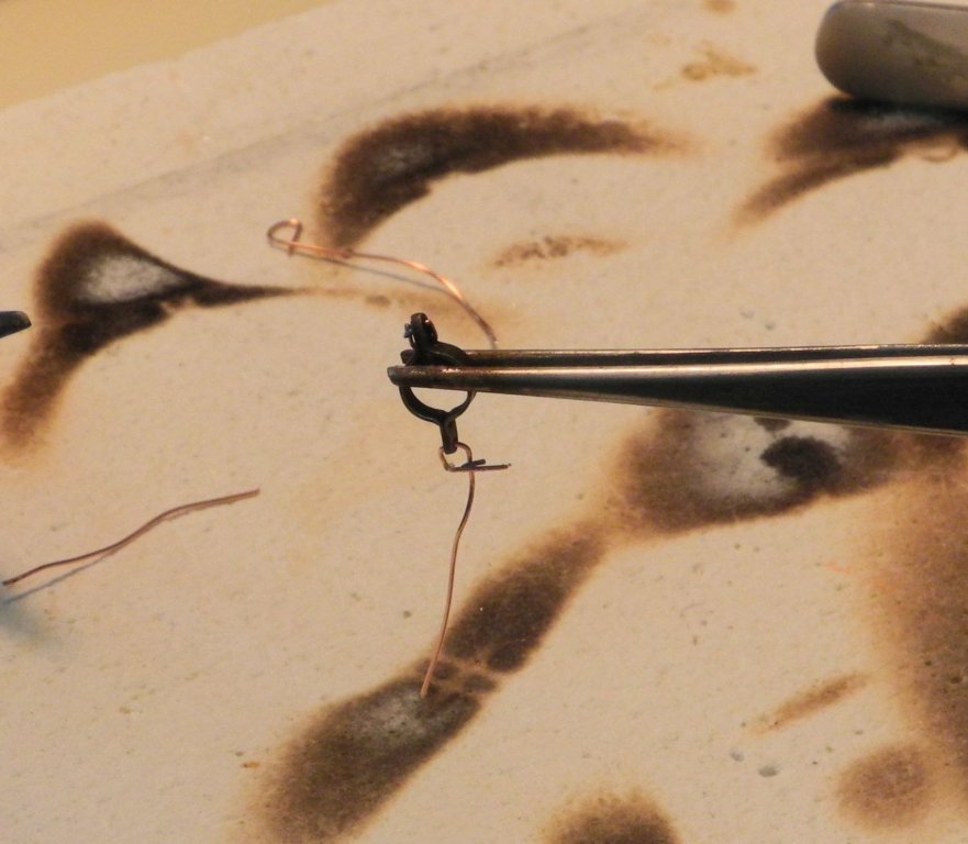
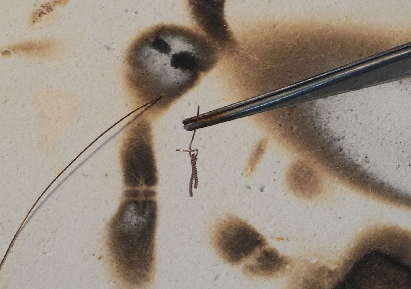
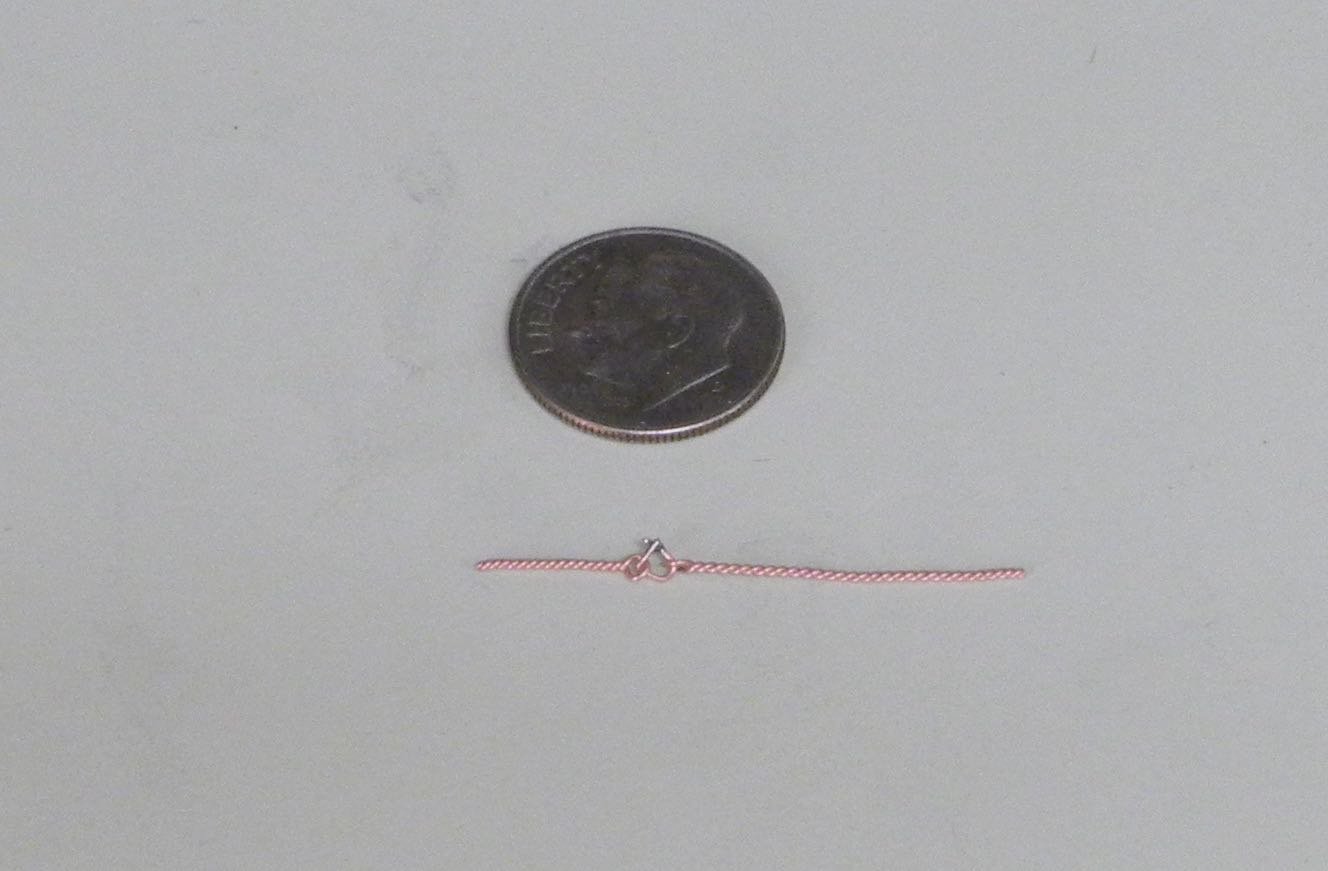
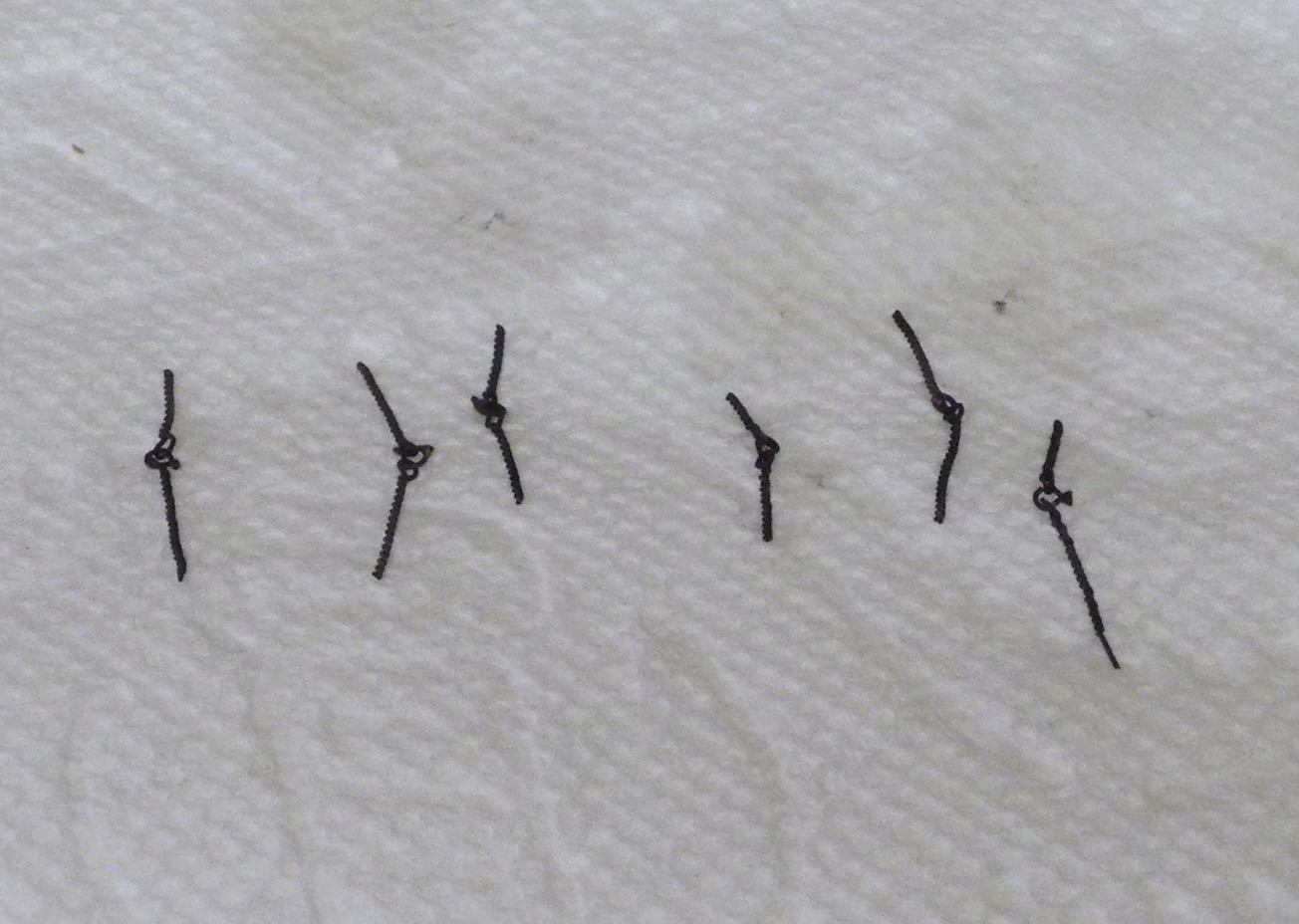
Almost every rigging connection on Kathryn includes shackles. After trying several approaches for making shackles, I decided to use the following.
First, using a diamond cylinder on a rotary tool, a small needle-nose pliers was shaped to serve as a form for the ‘U’ shape of the shackle.
A copper wire (in this case 26 gauge) was held in the pliers and then wrapped around one of the jaws of the pliers.
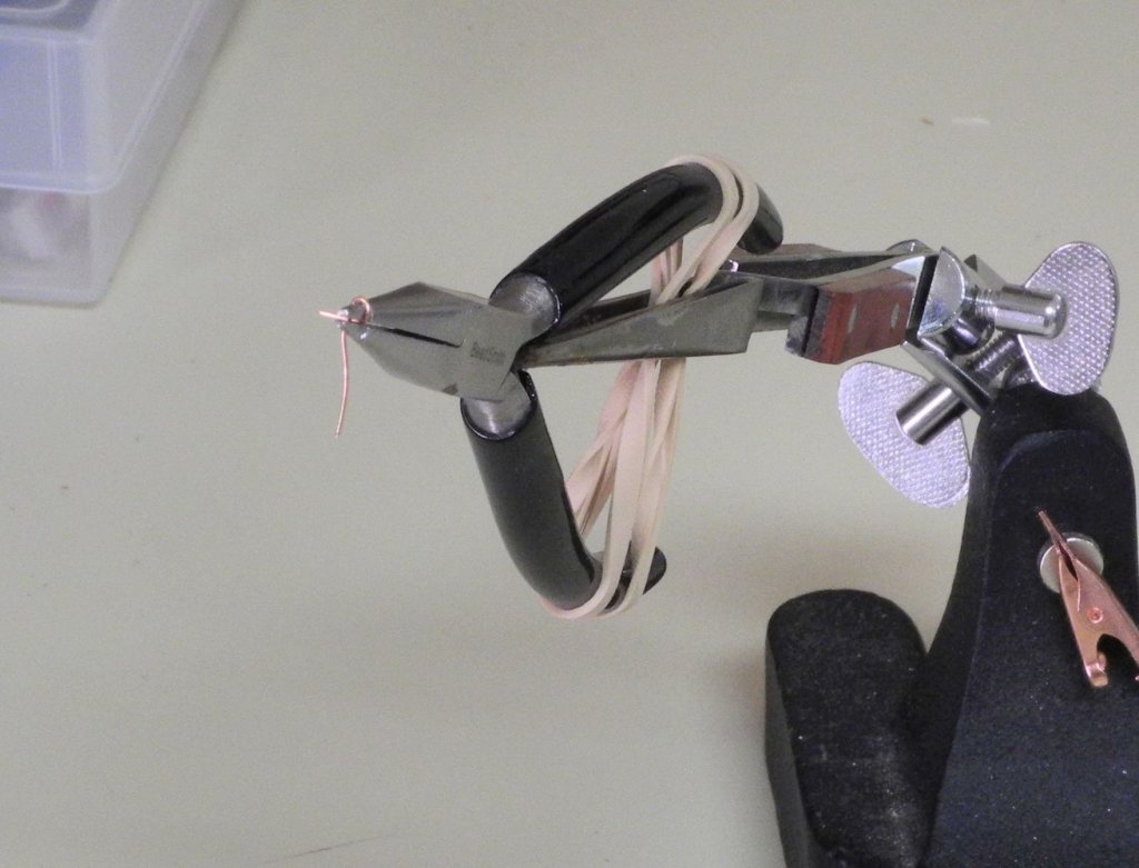
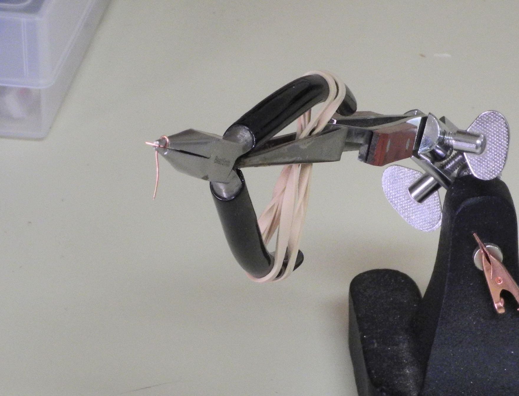
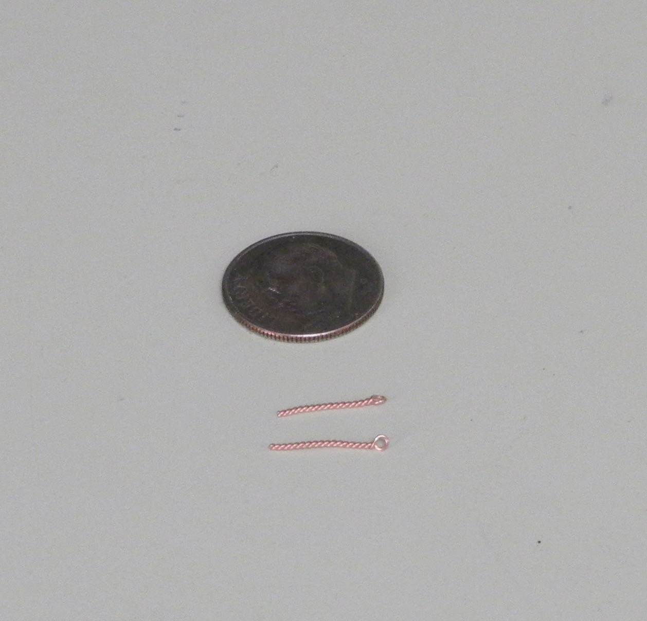
In developing this approach, I first attached ringbolts to the shackles.
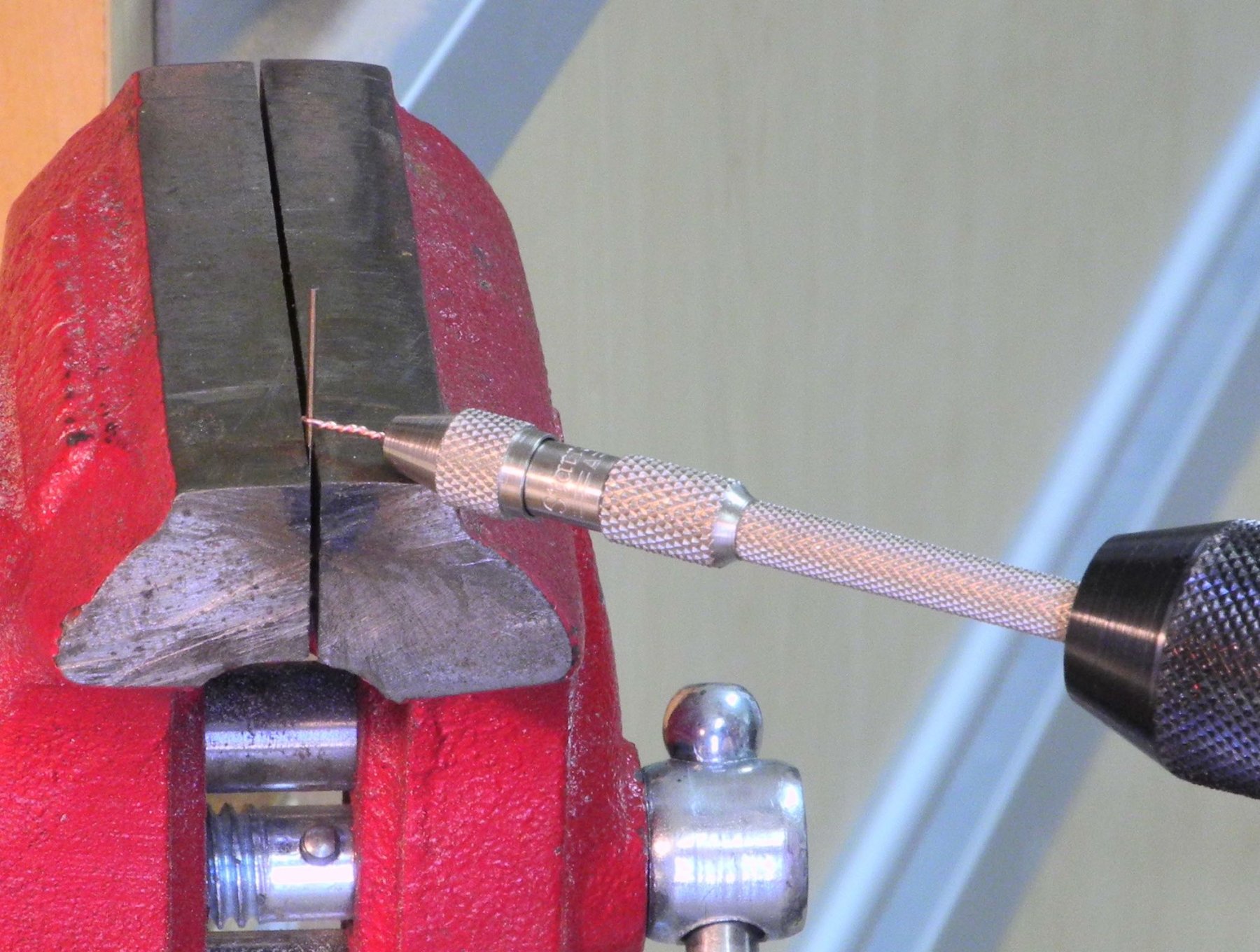
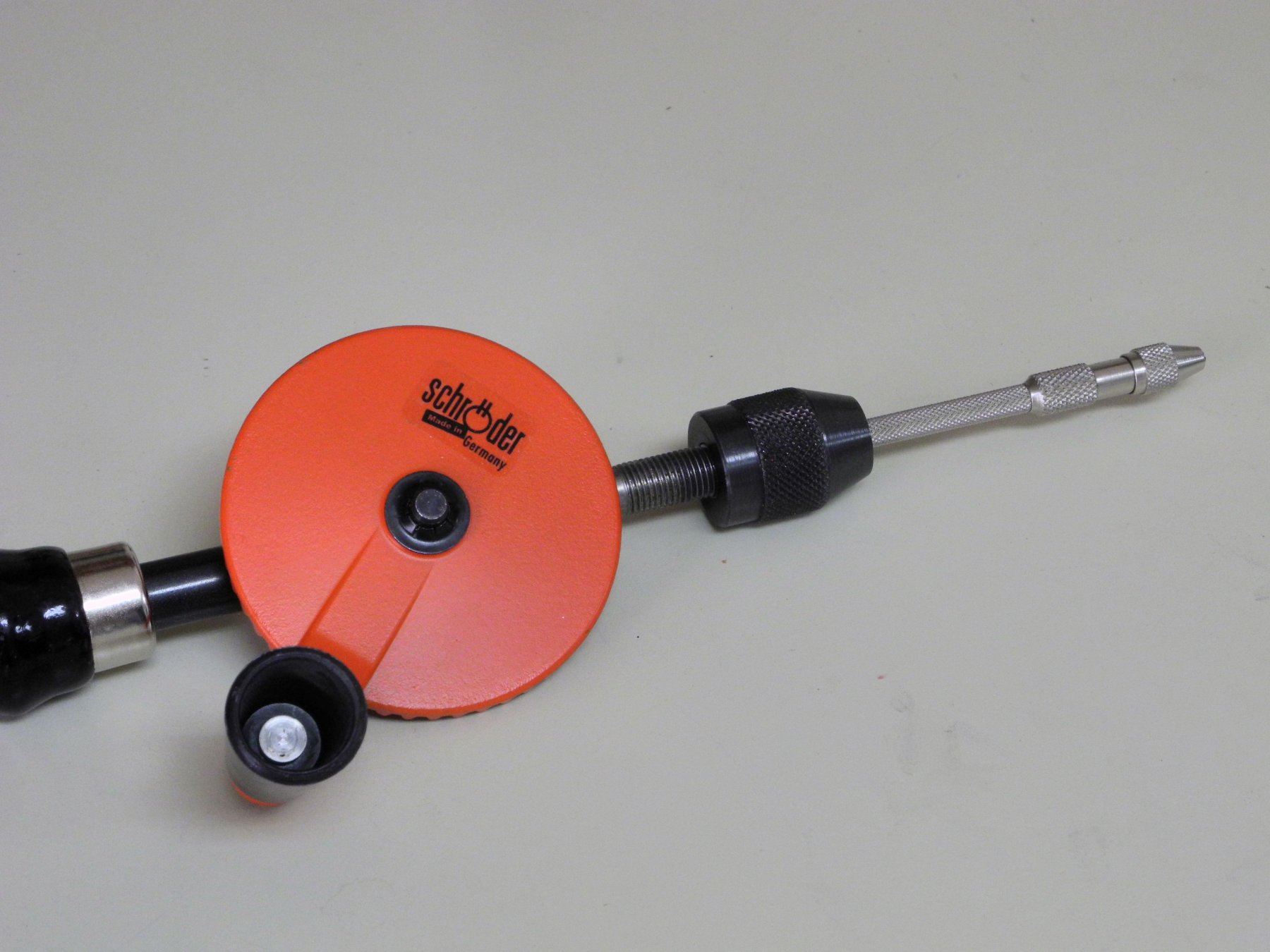
The ringbolts were made by twisting copper wire around an appropriate sized drill.

The pin vise holding the copper wire was in turn held by a manual drill, which made the ring-making process fast and efficient.

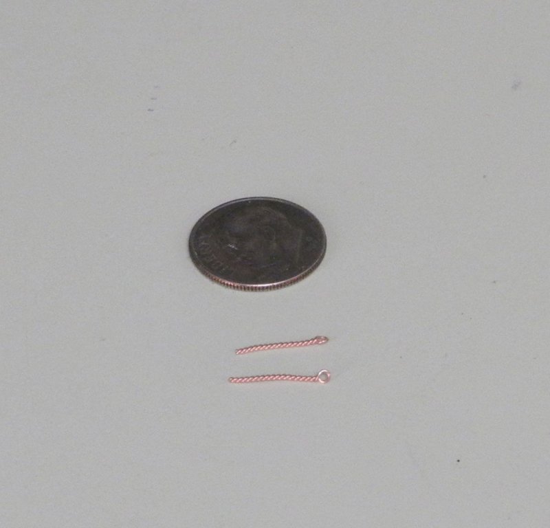
The rings were added to the shackle and the shackle was then soldered closed.

The excess ends of the copper wire were then clipped from the shackle, and the assembly was blackened.
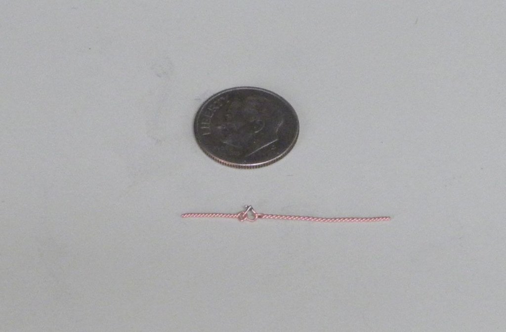
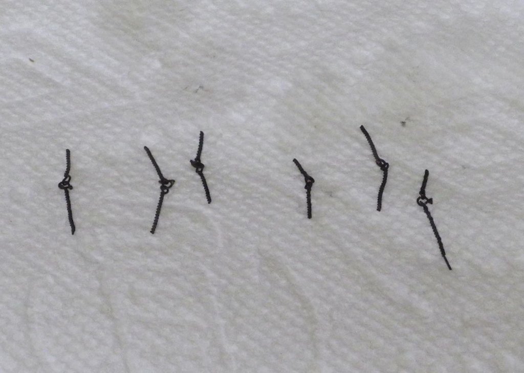
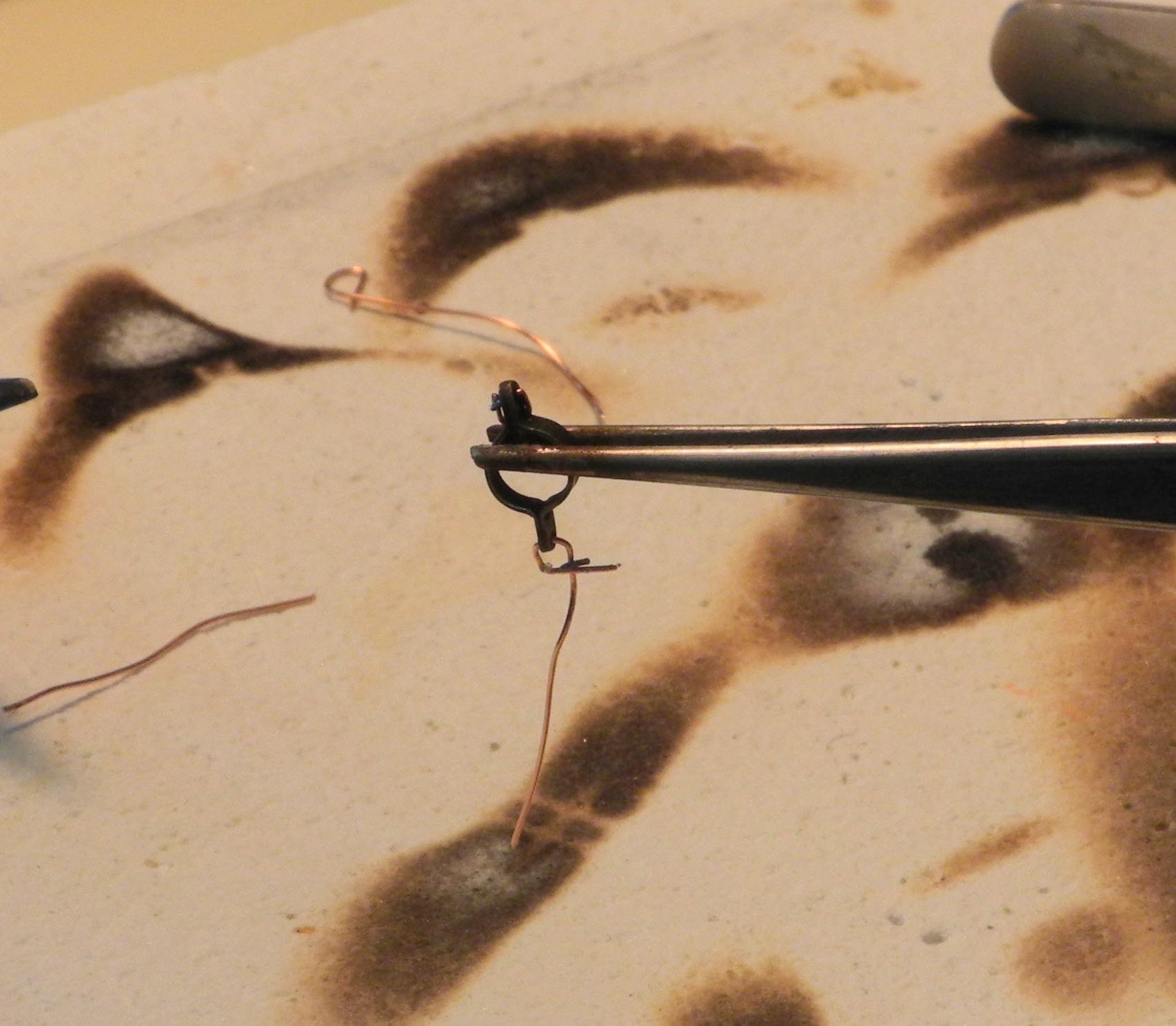
After successfully attaching ringbolts to the shackles, I moved on to attaching shackles to the boom and mast rings that had previously been made.
The shackle was added to the ring and was then soldered closed using the tweezers setup of the resistance soldering unit.

After cleanup and blackening, the rings are ready for mounting to the boom and mast.
There are still a lot of preparations to be completed before rigging can actually begin. The next few posts will likely be concerned with those preparations.
Cheers!
-
-
6 hours ago, popeye the sailor said:
really superb progress Frank........truly great progresses to watch
") really enjoying how you make the parts
really enjoying how you make the parts
Thanks Popeye, glad you're enjoying it.
4 hours ago, cog said:Frank, exceptional, you even got Popeye stumbling over his words!!!
LOL - Thanks Carl!
- mtaylor, thibaultron, Canute and 2 others
-
5
-
On 6/20/2018 at 9:10 AM, John Allen said:
Frank,
Followed since the first post could have commented on each and every post others stated what I felt. This build is so spot on it is awe inspiring from the smallest details to the metal work both you and Keith Aug are masters with no equals. Kudos belongs in a museum.
Thanks John. Just got back from my trip and will get back to work in the next day or so.
- thibaultron, Jack12477, mtaylor and 1 other
-
4
-
Thanks, Mark. Yes, the boom seems thin, but that's how it measures out from the HAER drawings and how it appears in photos. I should have mentioned that Kathryn's boom is laminated - that may contribute to its strength and size.
-
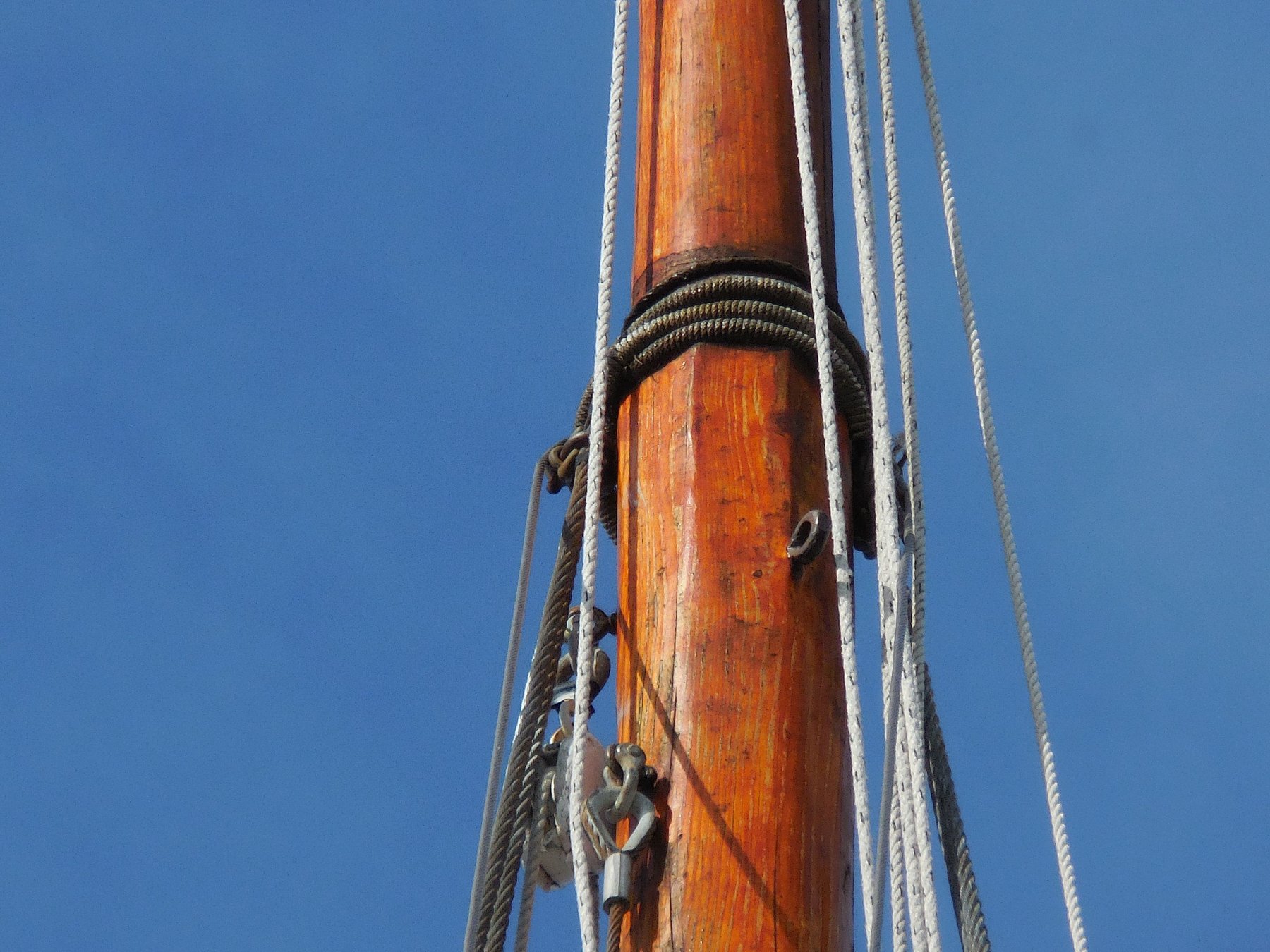
Part 66 –Mast Hounds, Boom
Kathryn’s mast has very small hounds, whose purpose is to provide a landing place for the shrouds and stays. The hounds are barely visible in the following photo of Kathryn’s mast.
Making the hounds was a simple process. Narrow tape was wrapped around the mast to indicate the top of the hounds. This ensures that the hounds on each side of the mast are at the same height.
The mast was clamped to the bench to make sure the area for the hounds were properly on the side of the mast. The area for the hounds was then cut in and flattened. A small piece of matching stock was glued in place and then shaped, stained, and finished with wipe-on poly.
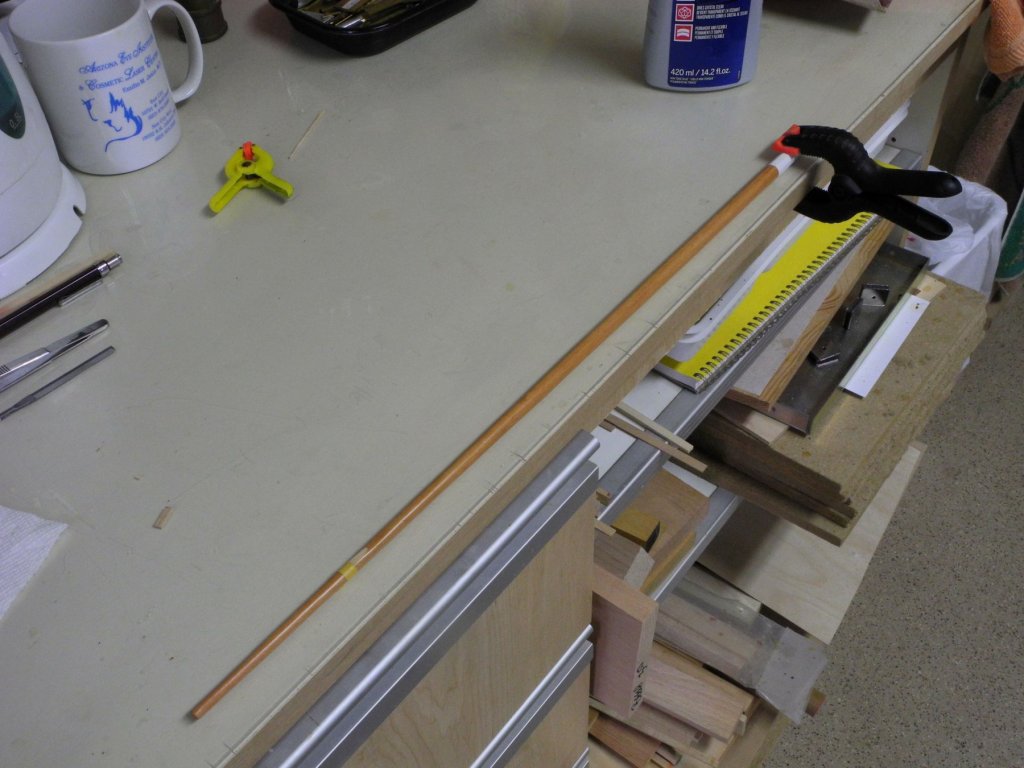
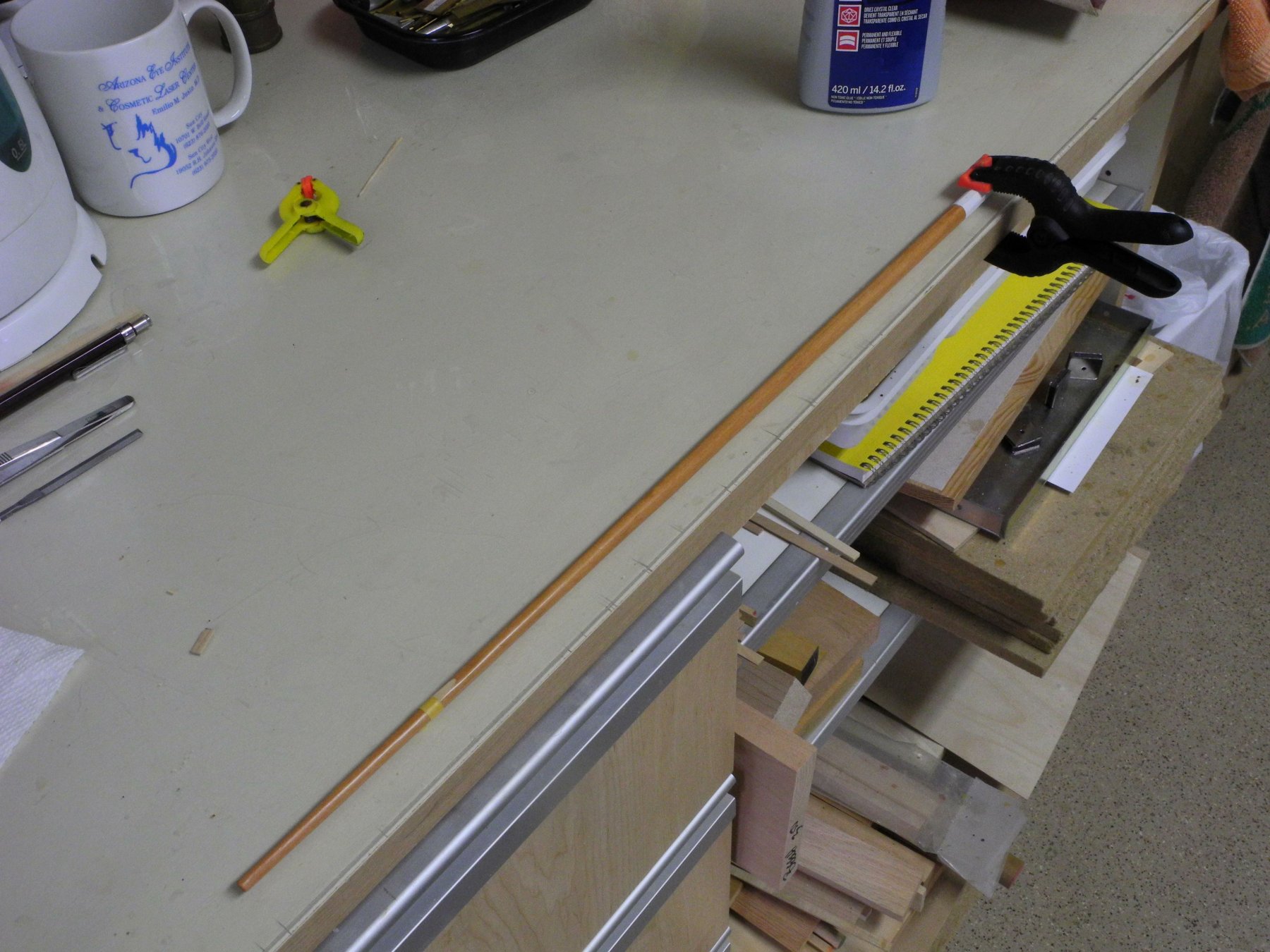
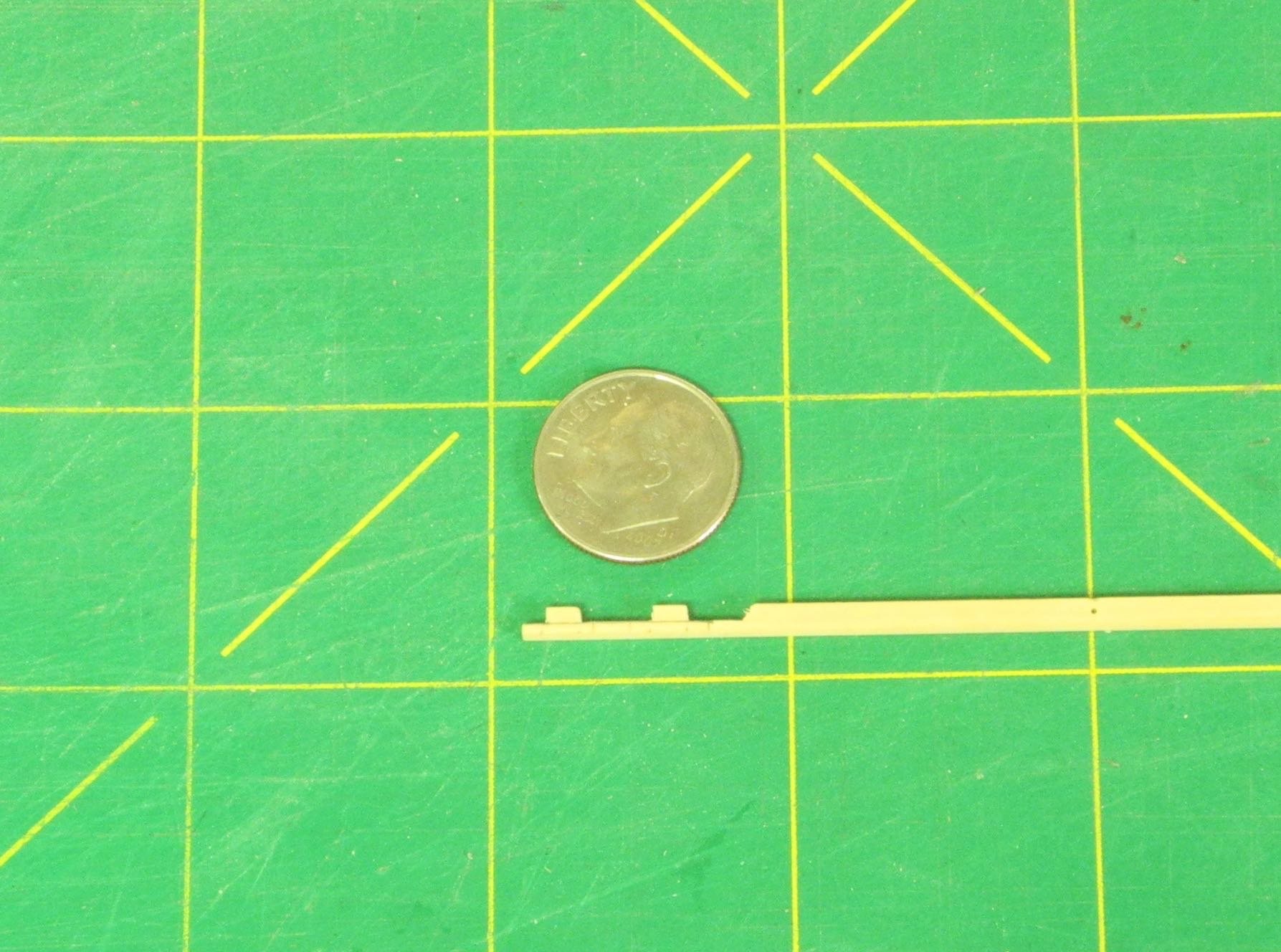
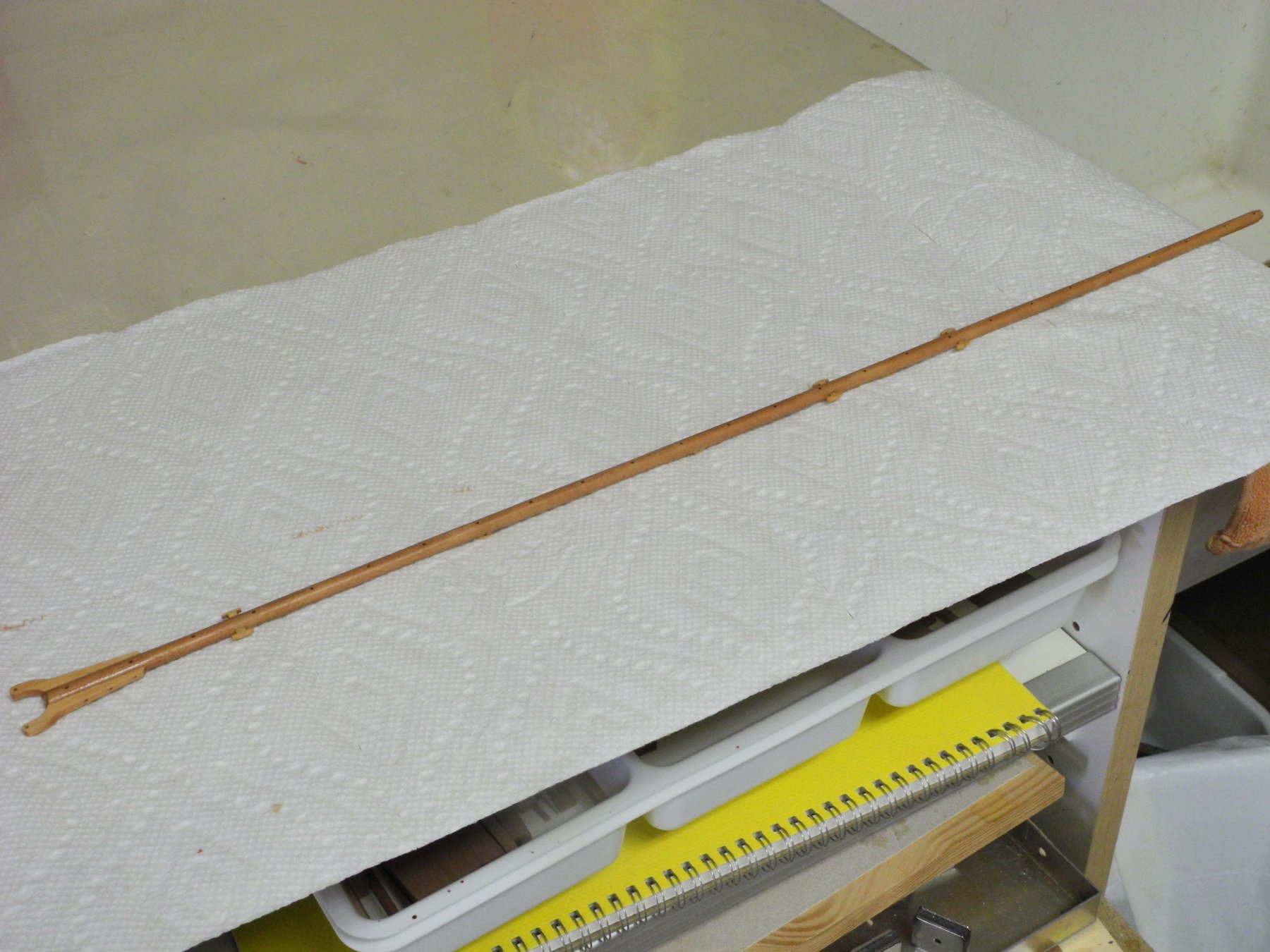
Kathryn’s boom is fairly complex, with a number of cleats and fairleads besides the jaws, and with some metalwork. There are ringbolts located every 24 inches along the top of the boom.
The boom was shaped from square stock, and after shaping it to the outside dimensions, holes for the ringbolts were drilled in the top surface.
The boom was rounded in the same way as the mast, using the 7-10-7 process illustrated in part 30.
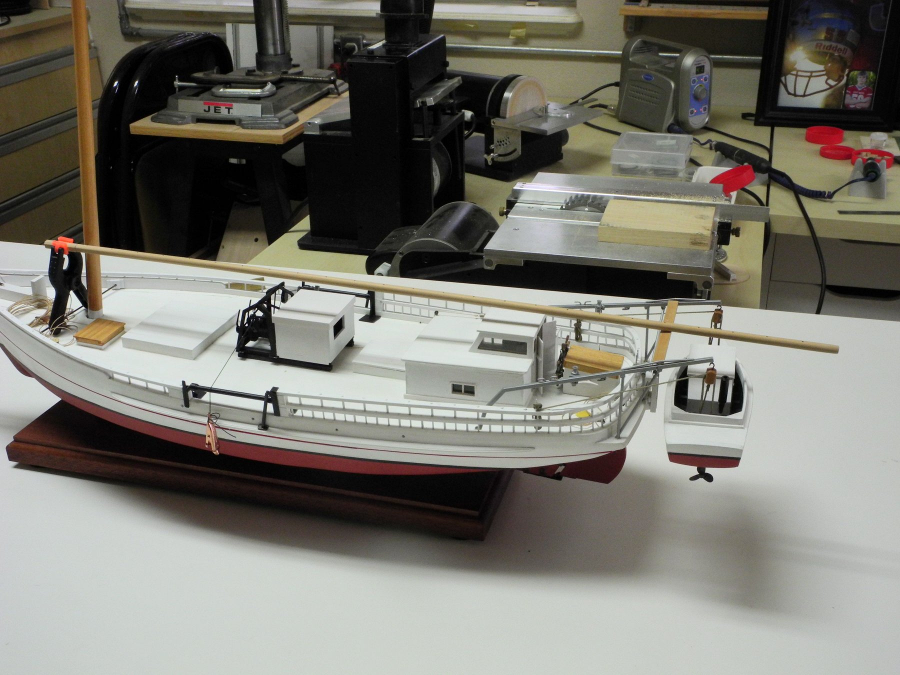
The following photo shows the rounded boom temporarily laid on Kathryn.

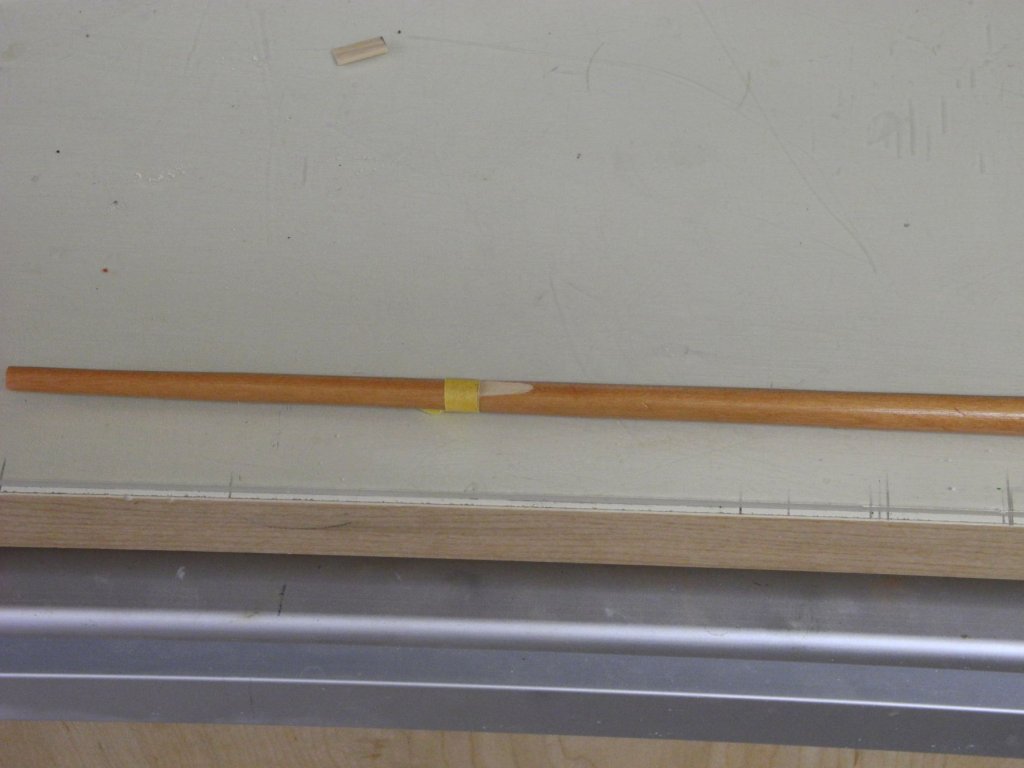
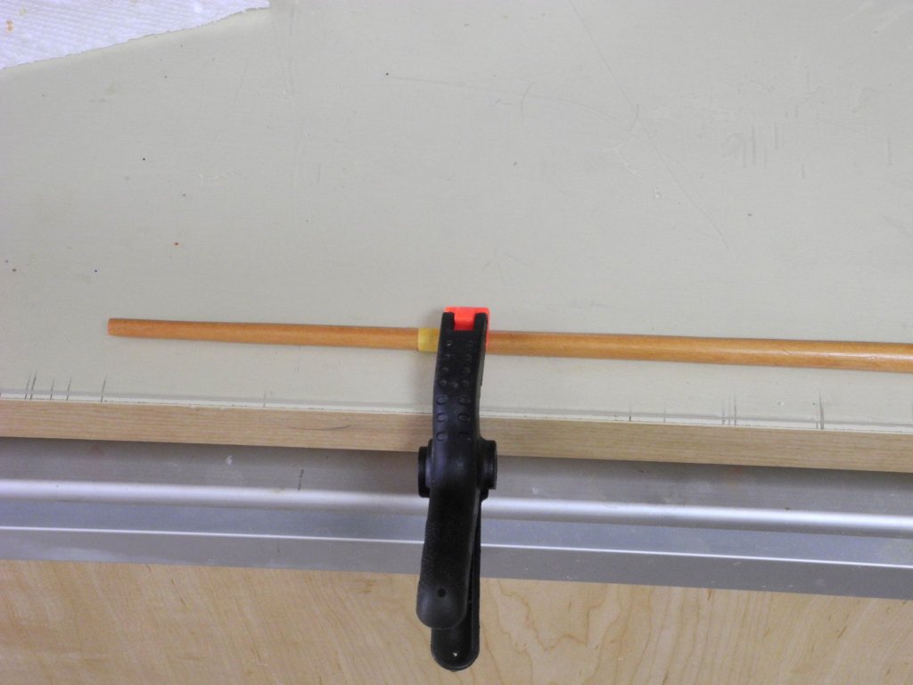
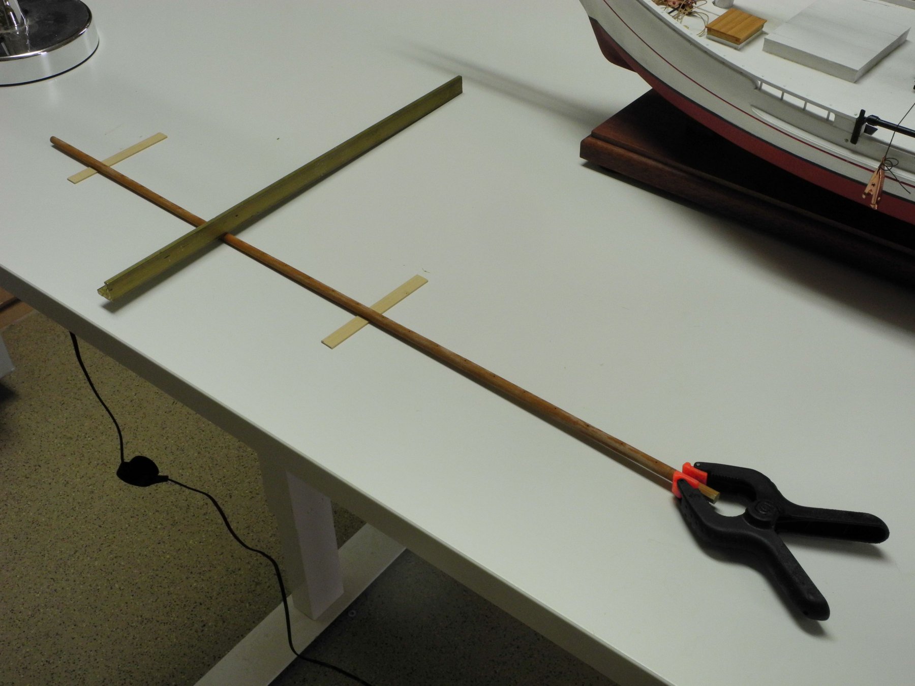
The booms on these old skipjacks (and many other ships as well) are no longer perfectly straight, even if they started out that way. Over time, the weight of the sail and the boom itself, will cause the slender boom to bend. In an effort to make the boom more realistic, a slight bend (about a scale 1 inch) was introduced in the boom. The boom was soaked in hot water inside a length of PVC pipe, and then was secured in a position that would let it dry with the slight bend.
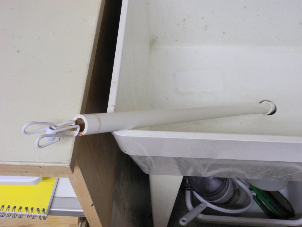
The weight used was a piece of brass angle, and the spacers on either side were 1/32” stock.
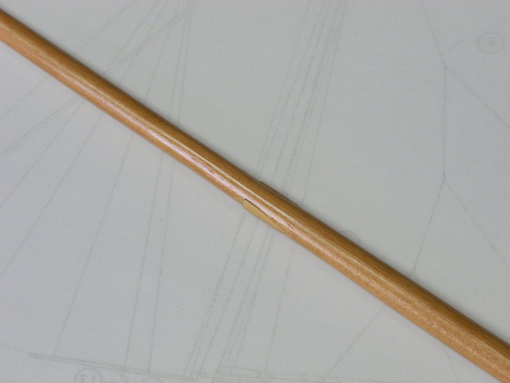
The topping lift and other rigging is attached to a ring located at the aft end of the boom. The area for the ring is slightly smaller in diameter than the rest of that portion of the boom
The area for the ring was marked out with masking tape. A shallow cut was made all around the boom as a stop cut. Wood was pared off the boom at the stop cut, and then a barrett file was used for the final shaping of the area.
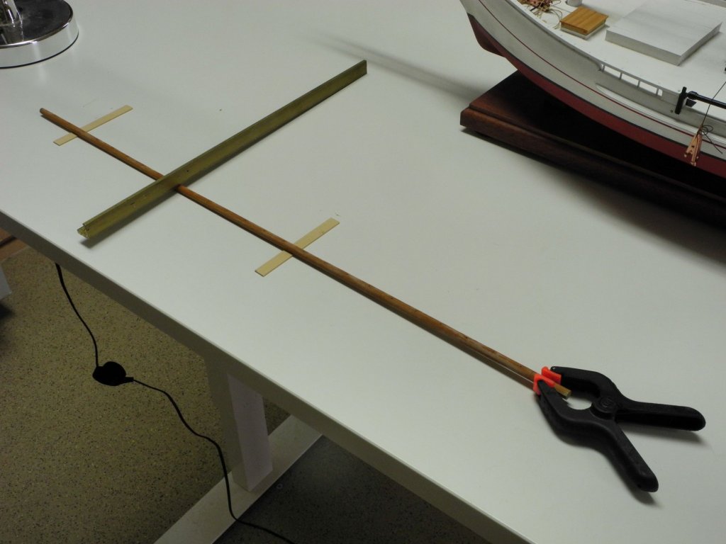
The forward end of the boom, within the jaws, is shaped to an angle as seen in the following photo.
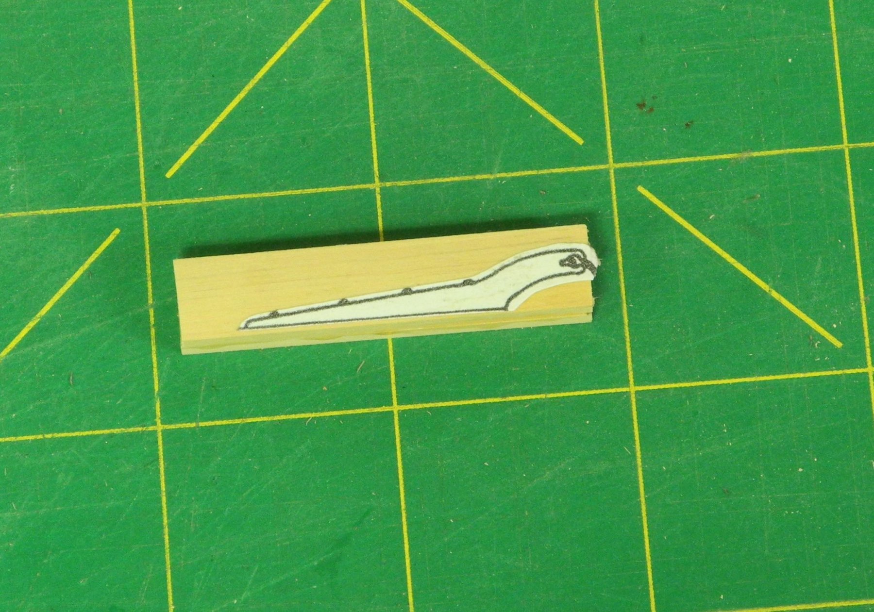
The jaws were made by gluing two pieces of stock together with Ambroid glue. The drawing of the jaws (taken from the Willie Bennett plans) was glued to the stock using a glue stick after the Ambroid glue cured, and the jaws were then cut out and shaped.

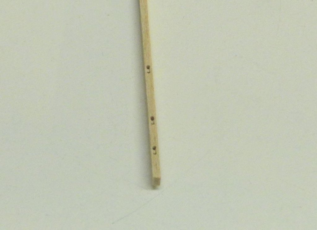
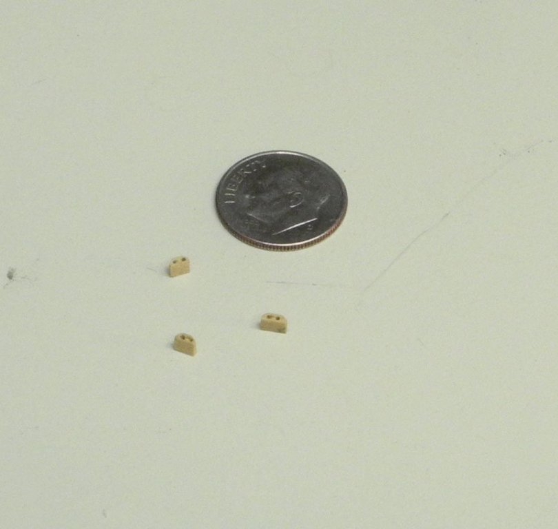
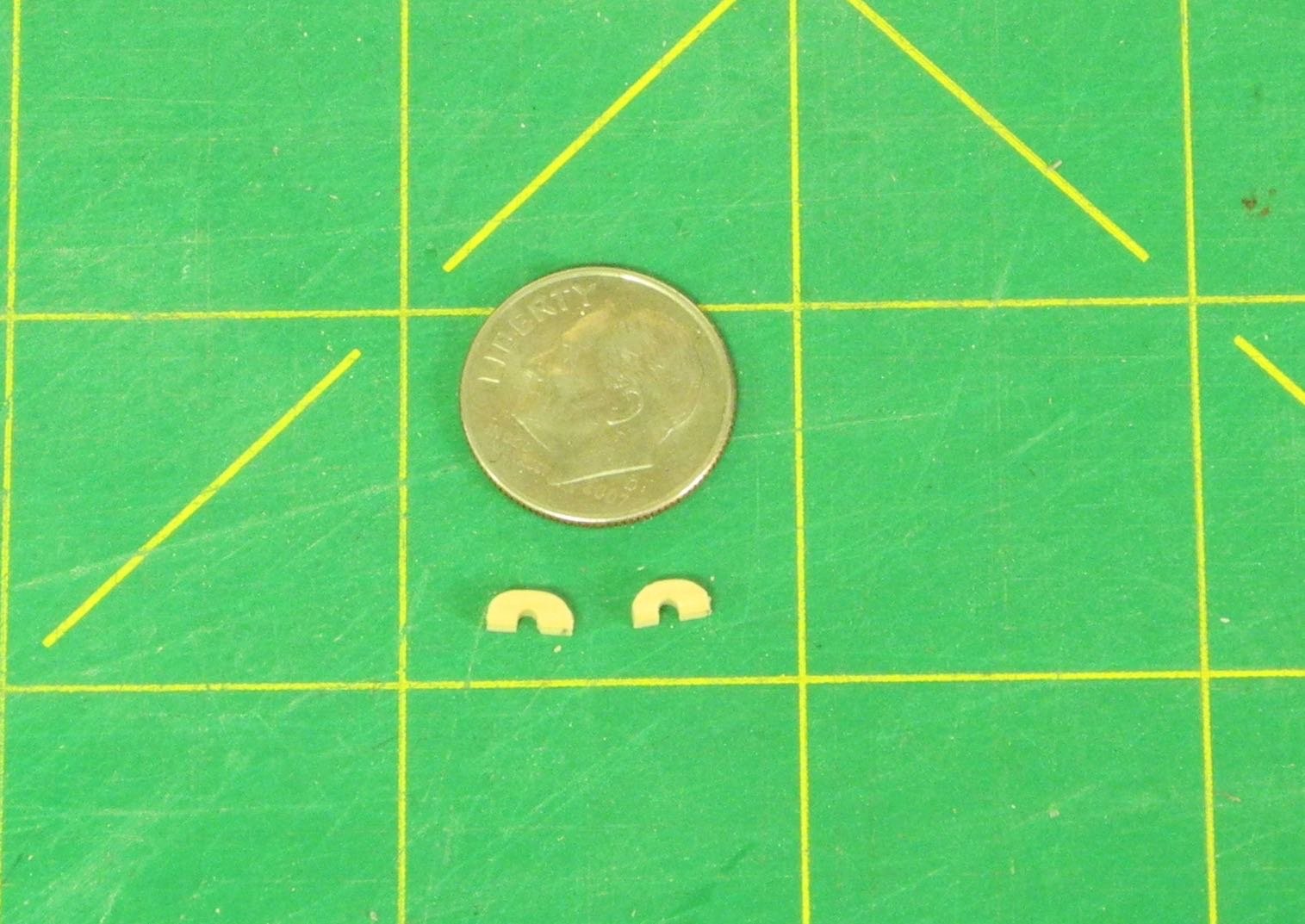
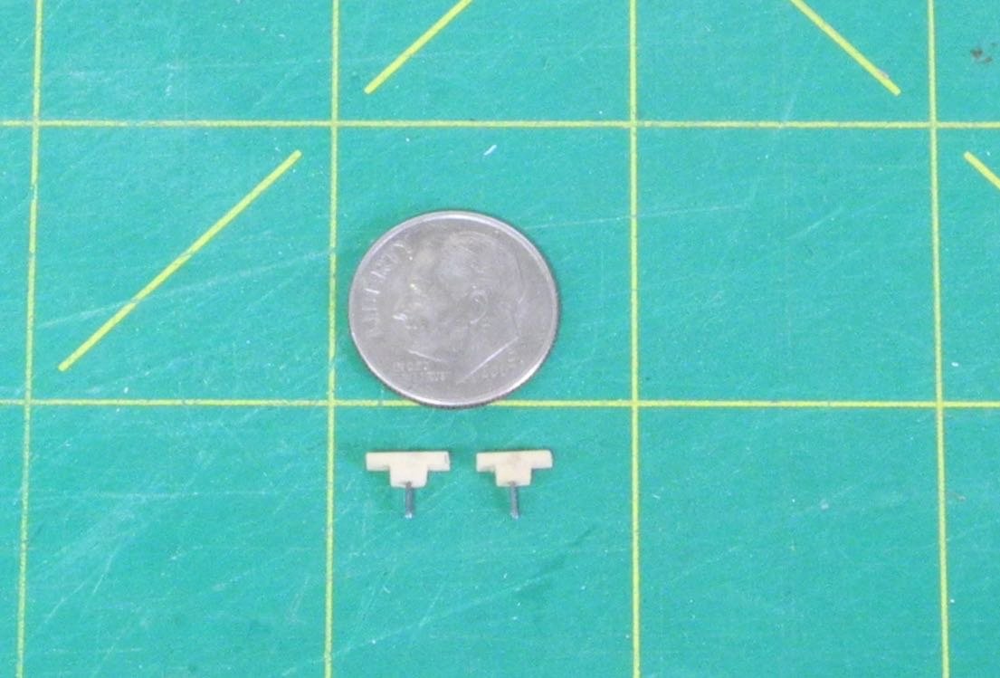
Kathryn’s boom has three fairleads for rigging the Lazy Jacks. These were made from 1/16” x 3/32” stock, and the shaping was accomplished using small files.
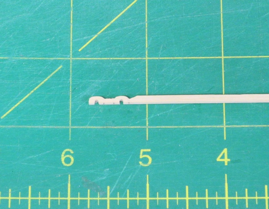

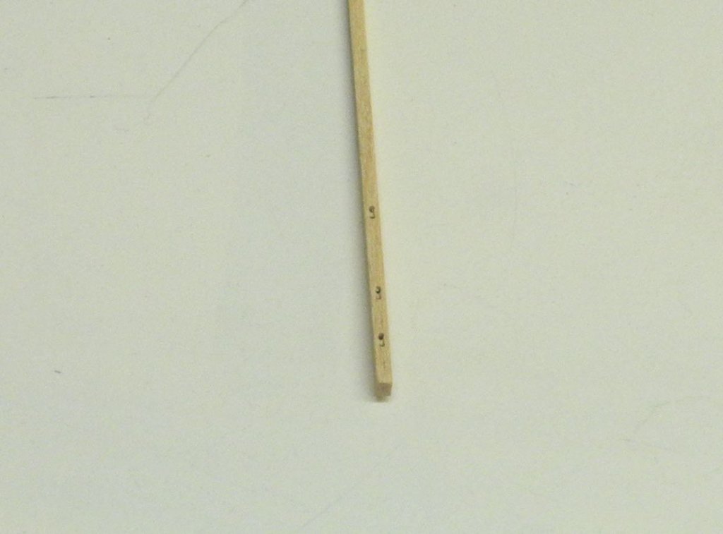
The boom also has a number of small cleats, which were made from the same stock as the fairleads. Since these will be used to tie some of the rigging, small posts made of piano wire were used to secure them to the boom.
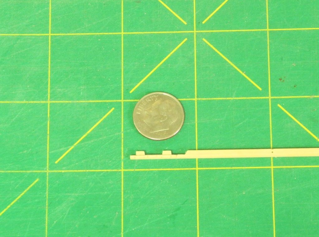
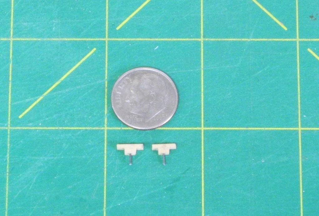
Final shaping of the cleats was done after they were securely glued to the boom.
The boom was then stained to match the mast. There are three wooden pieces remaining to be added to the boom. These are reefing blocks, and can’t be added until the metalwork is completed and attached to the boom.
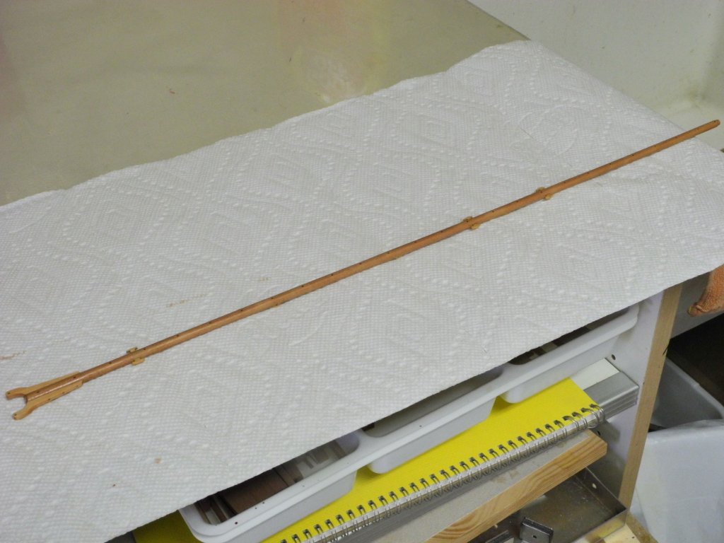
A poly finish will be applied after the boom is completed.
We leave on another trip tomorrow (to Calgary, for some cooler weather), so further work on Kathryn will be delayed for another short period of time.
In the meantime, I hope everyone is well and happy. Cheers!
- Calhoun Zabel, thibaultron, PeteB and 13 others
-
16
-


Kathryn by Mahuna - FINISHED - 1:32 - Skipjack Based on HAER Drawings
in - Build logs for subjects built 1901 - Present Day
Posted
Thanks John. It will be a while before I start working on the dredges. I'm focused on getting ready for rigging Kathryn, and will probably leave the dredges for last.