


Mahuna
-
Posts
1,501 -
Joined
-
Last visited
Content Type
Profiles
Forums
Gallery
Events
Posts posted by Mahuna
-
-
Part 79 –Mast Installation
Prior to installing the mast, any holes required for ringbolts, cleats, or other items were pre-drilled in the mast.
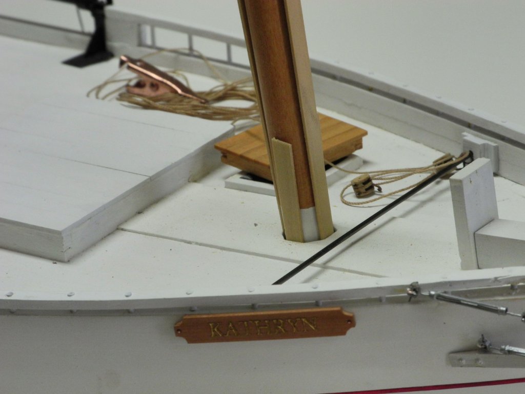
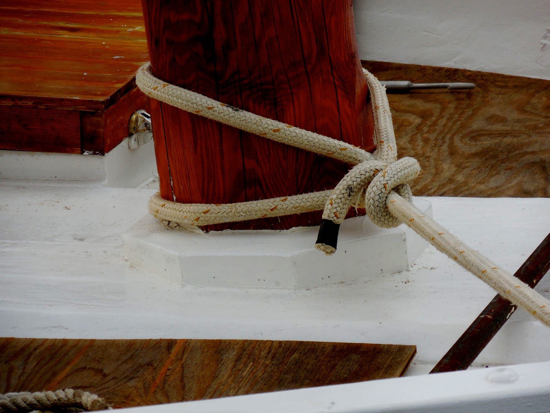
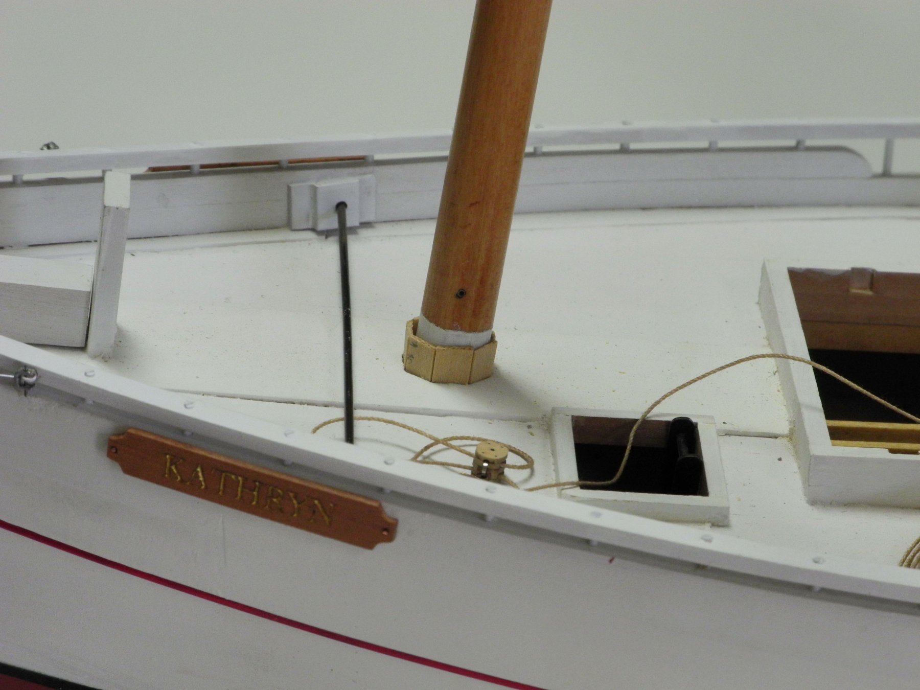
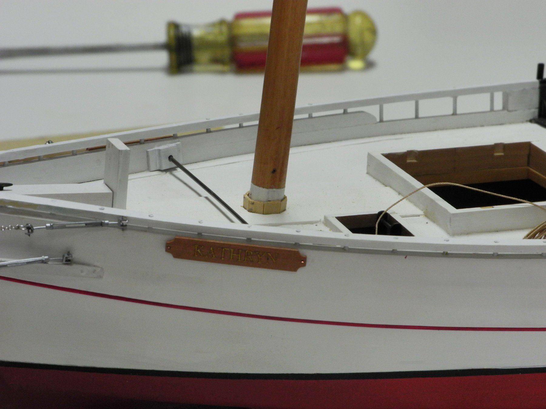
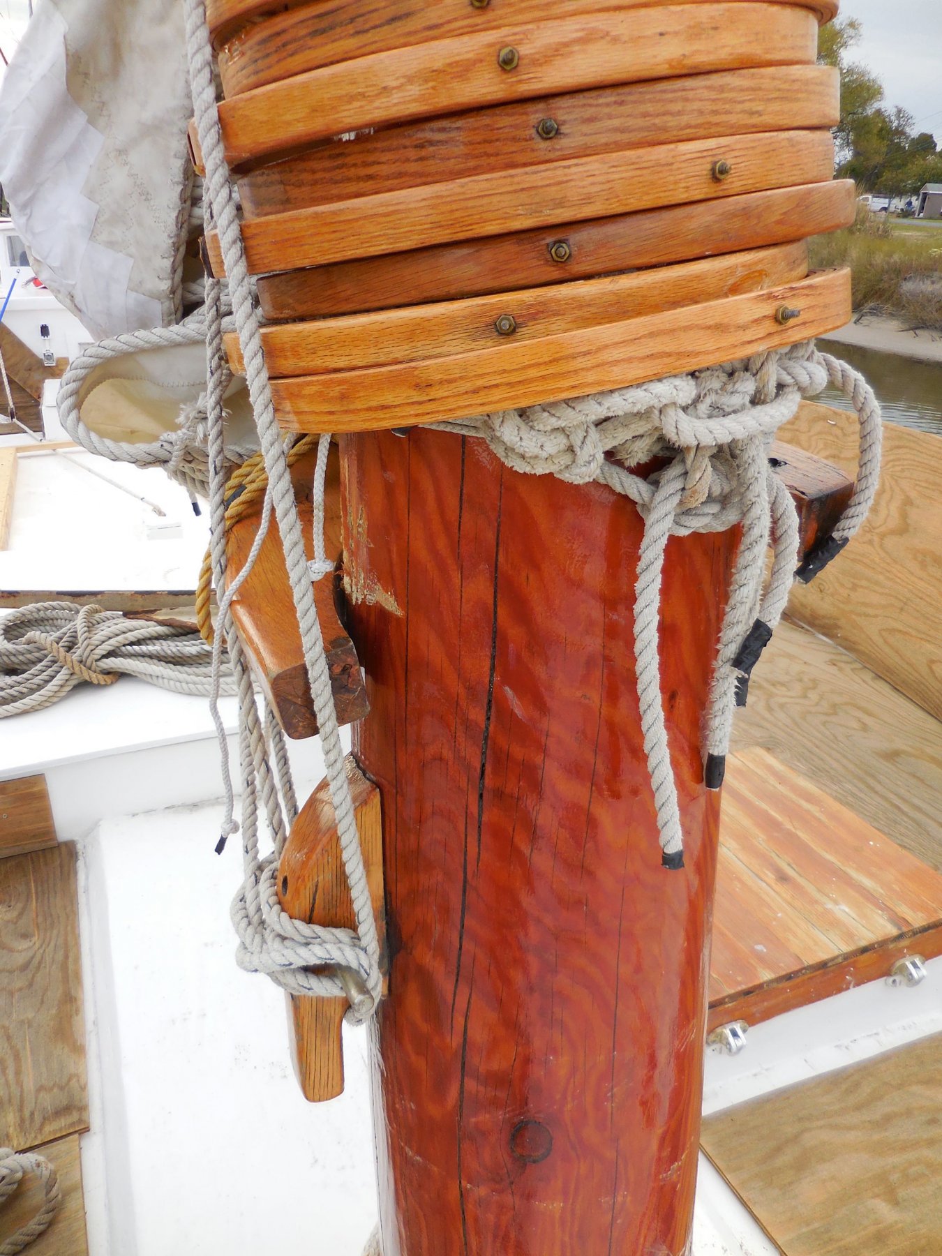
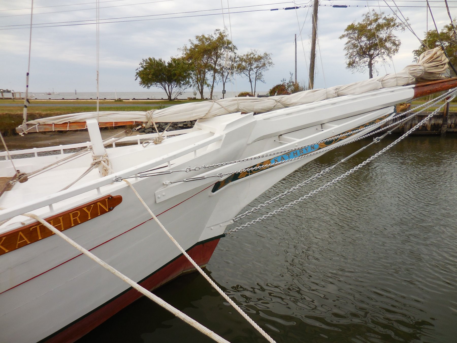
The tenon at the bottom of Kathryn’s mast sits in the mast step – or the mortise cut into the keelson. The octagonal hole in the mast partners allows enough room for wedges that will keep Kathryn’s mast properly centered and angled. The following photo shows these wedges installed and painted on the real Kathryn.

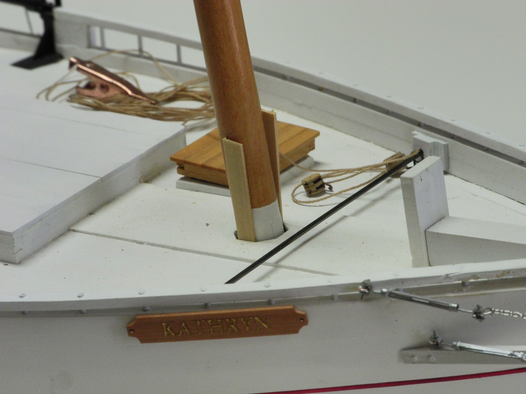
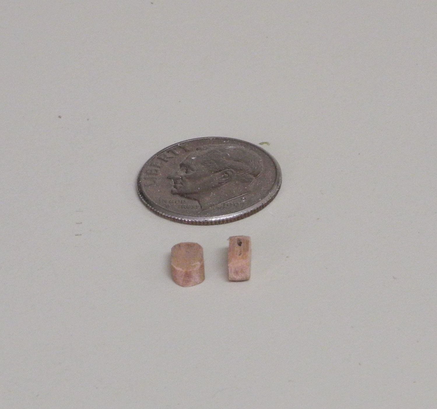
The first step in the installation of the model’s mast is to insert wedges on the sides of the mast to ensure that it is properly aligned vertically. The wedges used on the model are a little over 1” thick (1/32 on the model) with the sides beveled to fit in the octagonal openings. The beveling was done by sanding each piece by hand, using a sanding stick.

When the side wedges were satisfactory the fore and aft wedges were inserted.
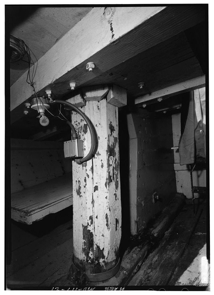
The stock used for the wedges was kept extra long while the fitting was being done – this allowed easy removal of a wedge for tuning the shape of the wedge. The same is true on the real Kathryn, as the following photo from the HAER survey shows.

Once all eight wedges were finalized they were initially cut to a satisfactory length.

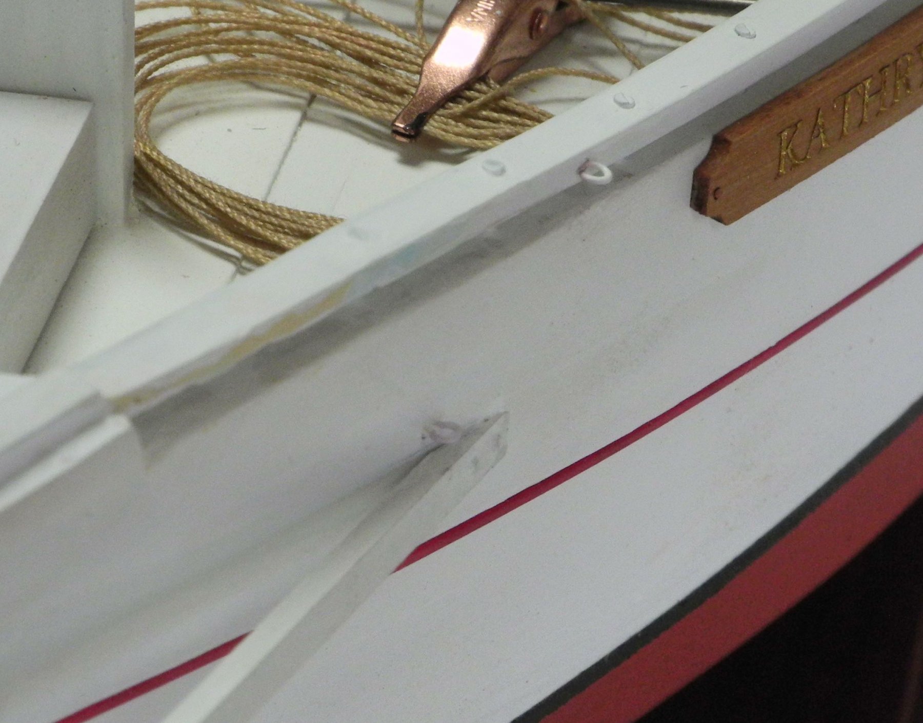
The wedges were then carefully tapped down to their final height above deck using a small jewelers hammer and a flat screwdriver. (When one wedge was tapped too low, it was possible to raise the ledge by prying it up with a small awl.)

The mast wedges were then painted to match the mast. No filler was used – the paint was thick enough to fill any small openings between the wedges or between the wedges and the mast.
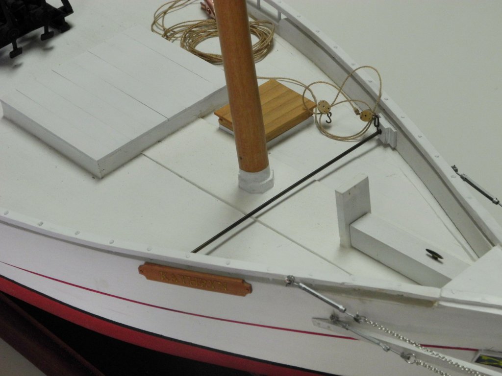
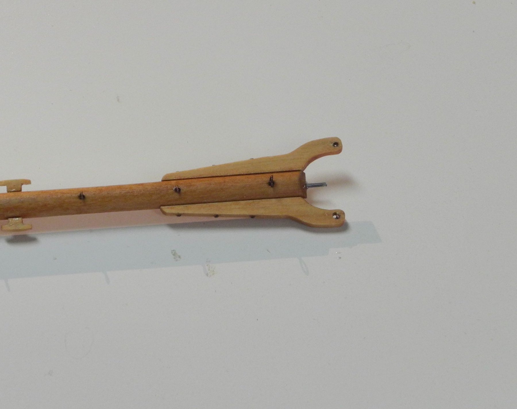
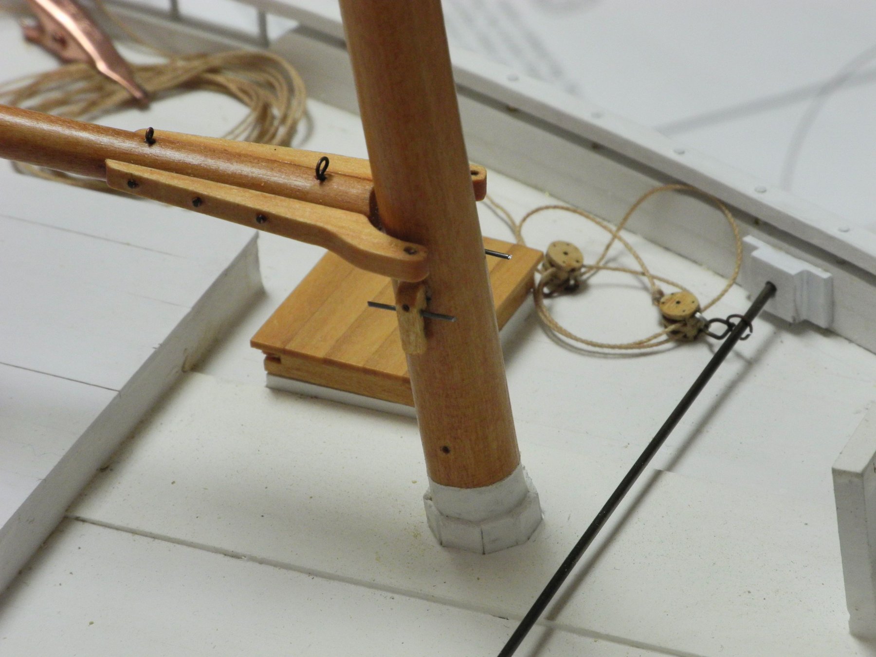
A hole had been drilled at the point where the boom sits on the mast, and a corresponding piece of piano wire was installed in the boom to hold it in place on the mast.
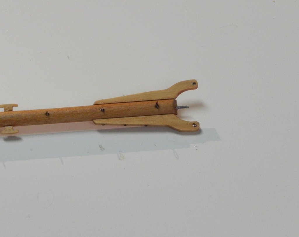

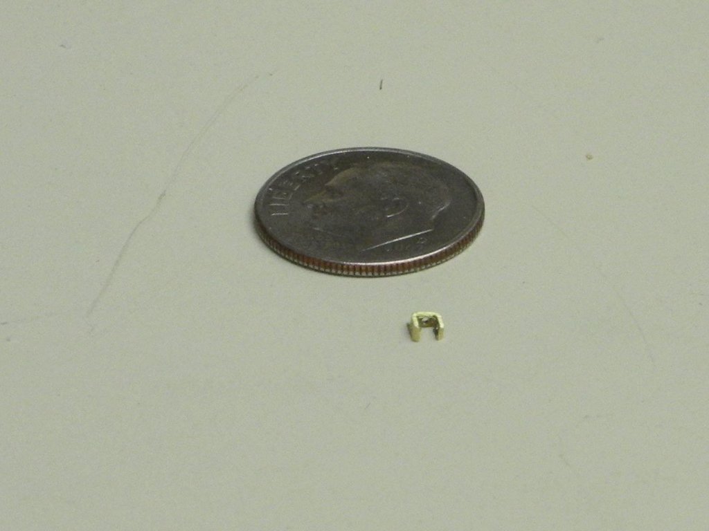
Finally, there are two mast cleats, one on each side, just below the boom jaws.

Each of these cleats has a longitudinal metal bar running through it, as seen in the prior photo.
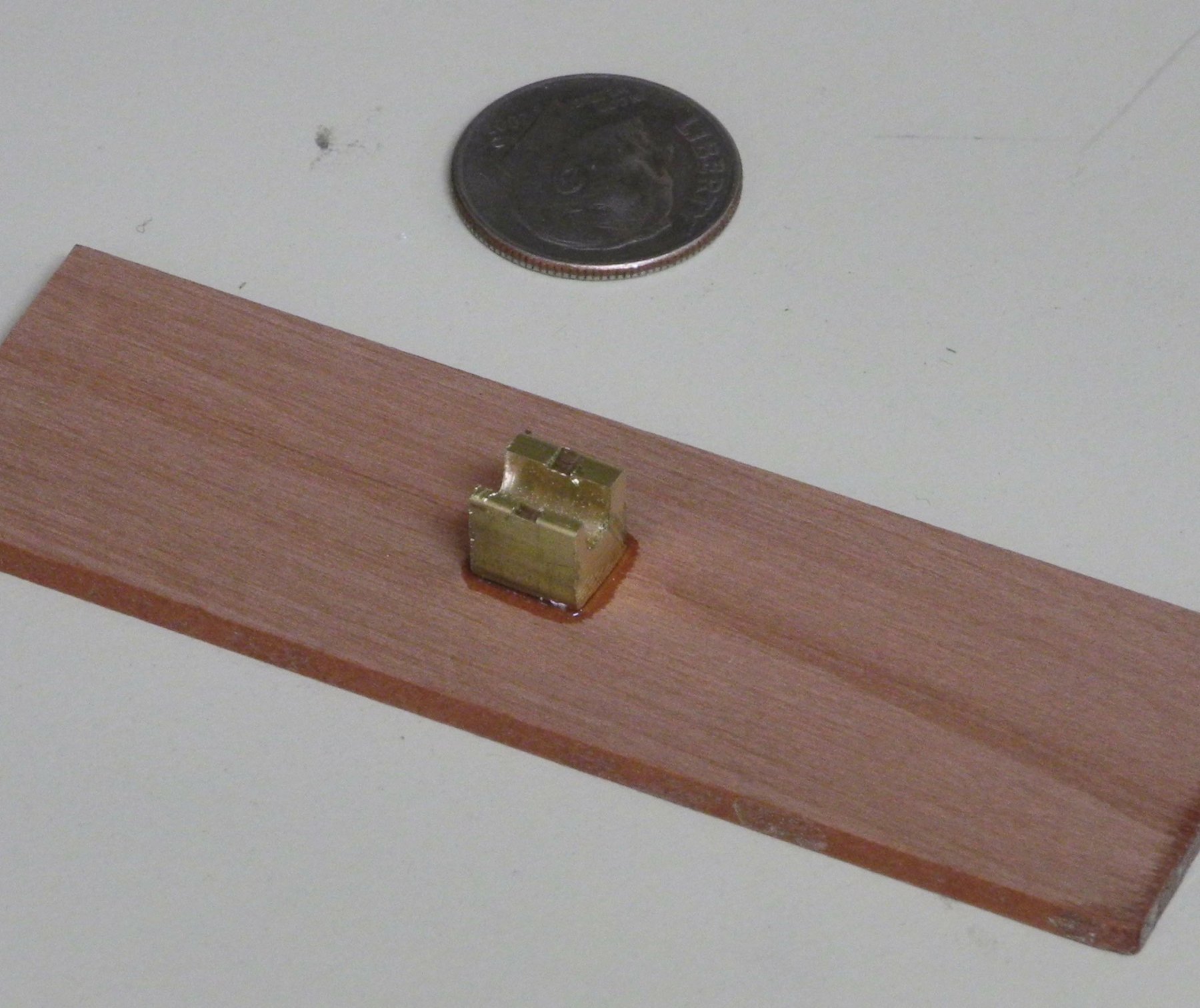
The cleats were each made form a single piece of 3/32” square stock. After shaping, holes were drilled for a mounting peg and for the longitudinal bar which were all made from piano wire.
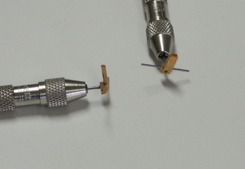
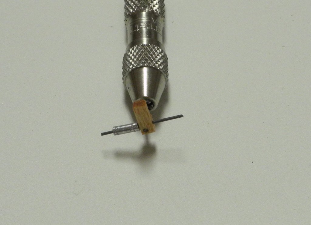
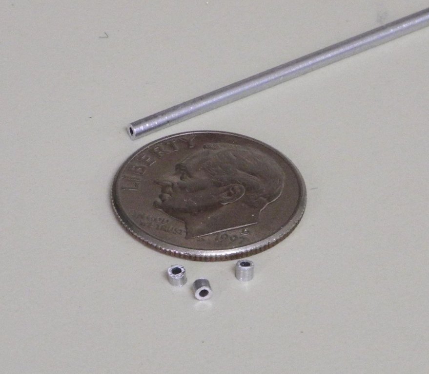
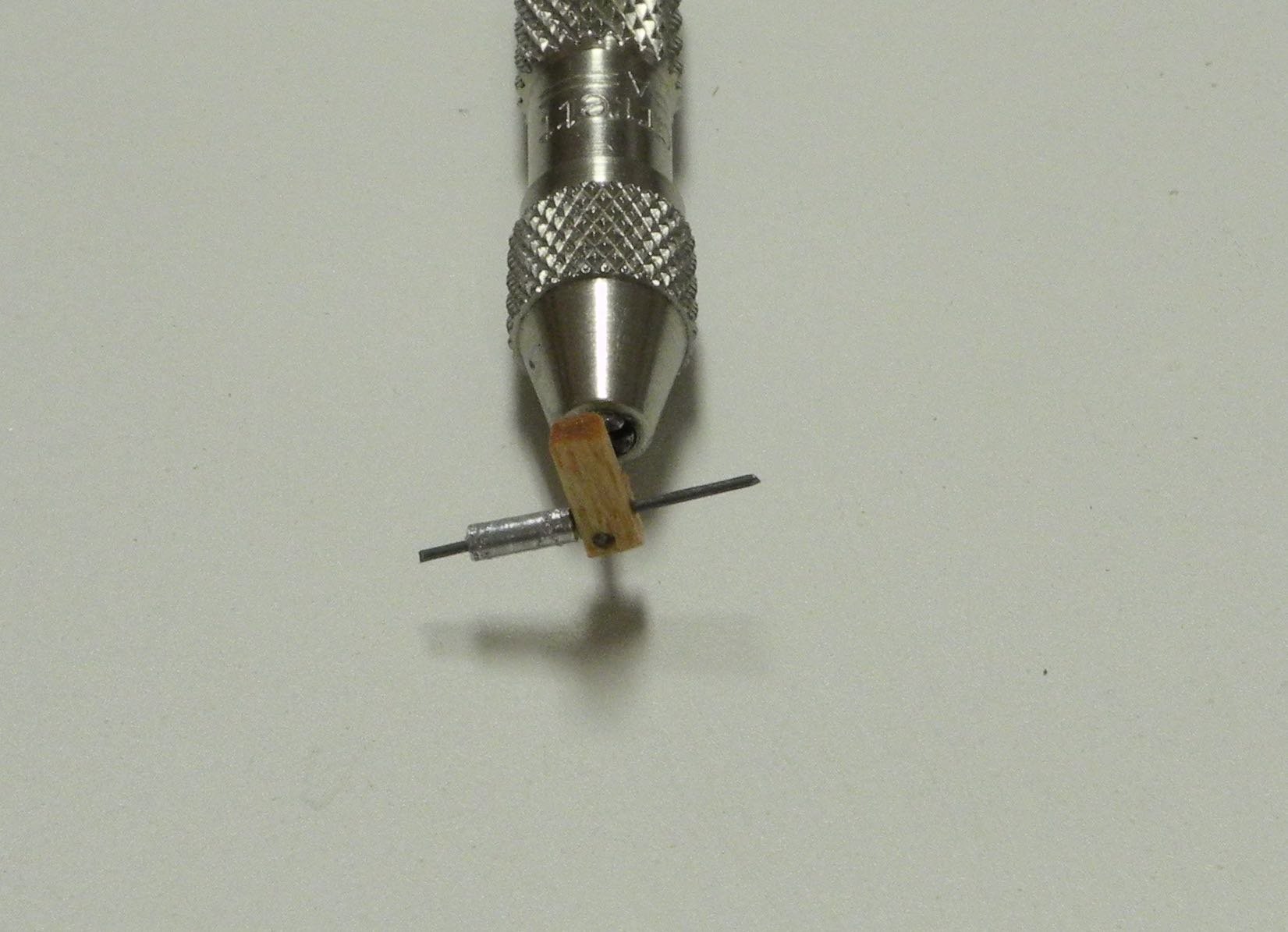
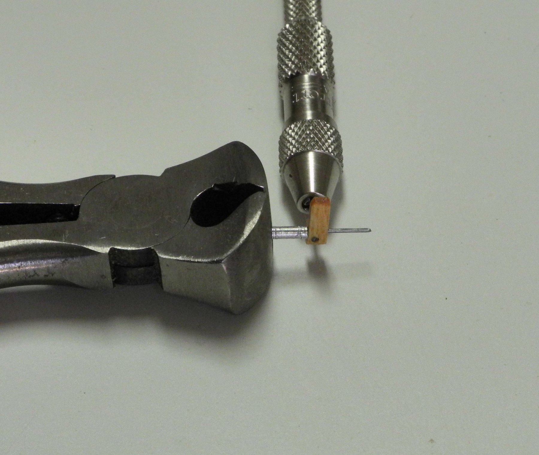
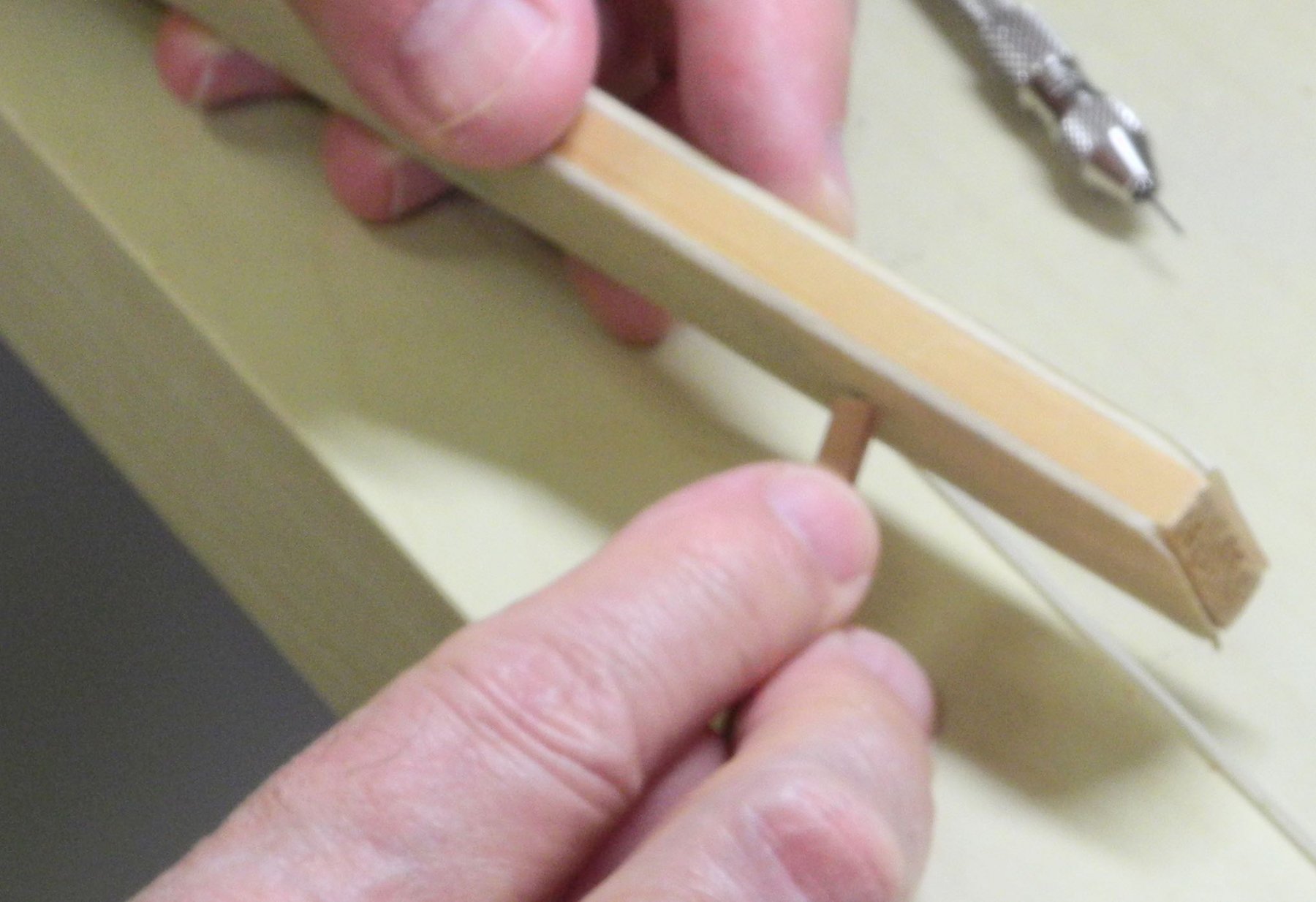
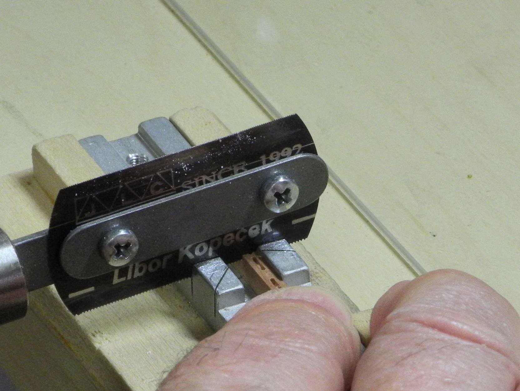
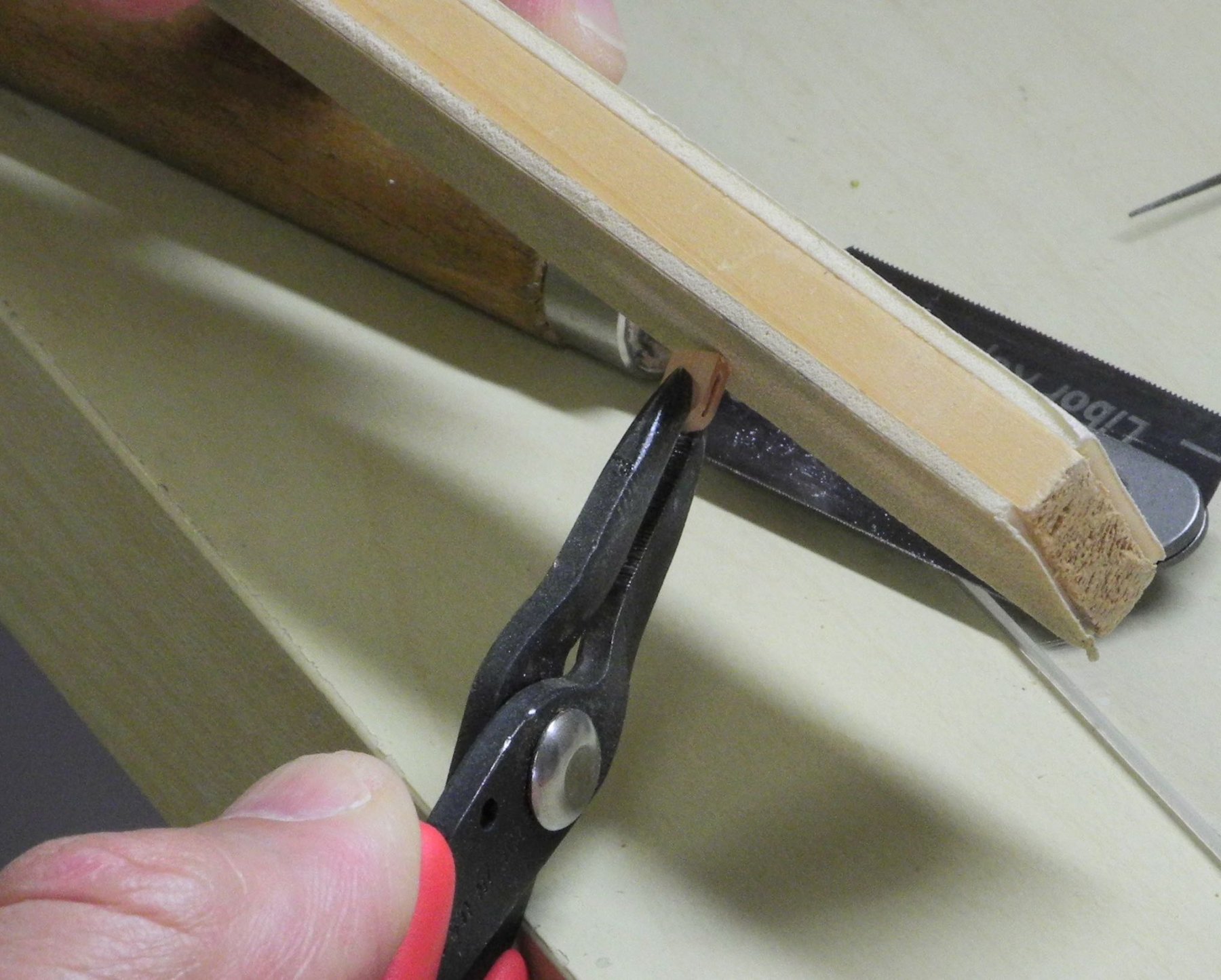
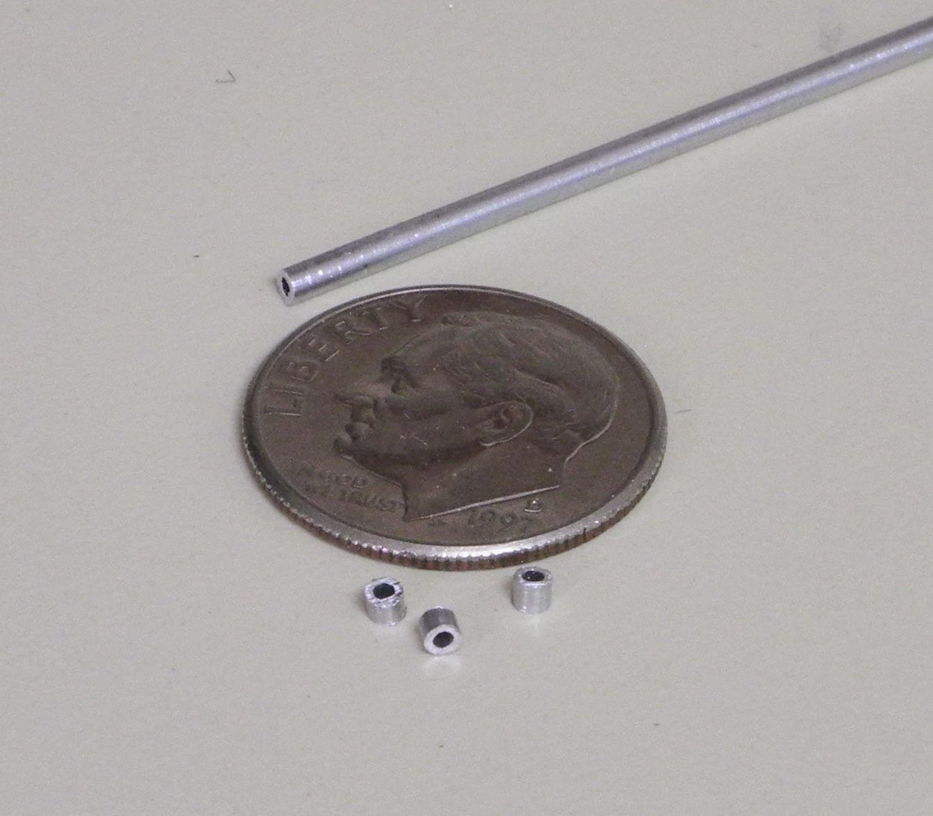
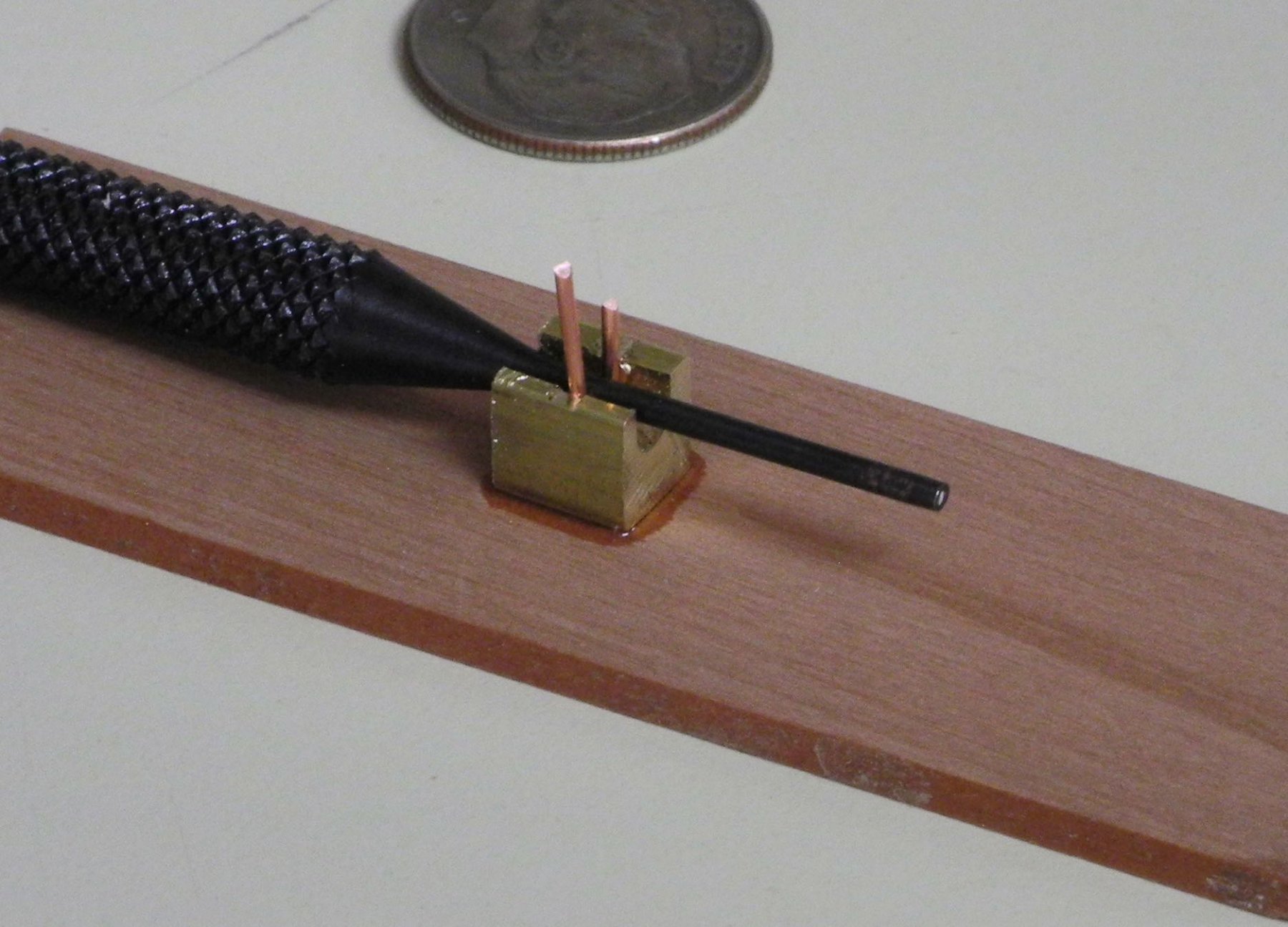
The longitudinal bars were oversized when installed. After staining and an application of wipe-on poly on the wooden cleats, these bars needed to be trimmed to size. All of the protruding lengths of these bars needed to be the same, so a small ‘jig’ was used as follows. A piece of aluminum tube was cut to the final length and was slid over each side of the bar…
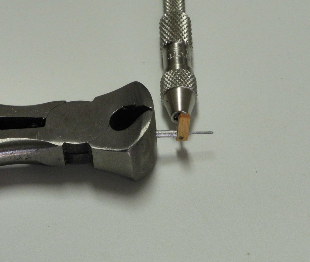
and the bar was trimmed to the final length using a small nipping pliers.
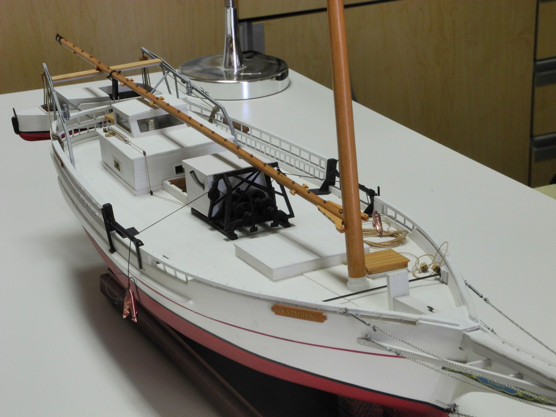
So the mast is now in place, and Kathryn is now ready for rigging.

Thanks all!
- albert, paulsutcliffe, hexnut and 19 others
-
 22
22
-
Thanks John - I started out as a software engineer and finished up in project management, so I guess some of that does come into play.
- Jack12477, thibaultron, mtaylor and 4 others
-
7
-
Ha ha - Rich, you have a way with words! Thanks.
- popeye the sailor, HIPEXEC, mtaylor and 2 others
-
5
-
8 hours ago, GuntherMT said:
Great work Frank... but man you are just way too organized for me. 😂
1 hour ago, EdT said:Beautiful work, Frank - and so well organized.
Ed
Thanks Brian and Ed. I've found that if I don't put things away in some order then I either don't remember what they are for or I lose them. To me, organization is a defensive measure!
- Canute, michael mott, Roger Pellett and 5 others
-
8
-
-
Part 78 –Block Hardware
The next step in preparations for rigging was to add the required hardware to Kathryn’s blocks.
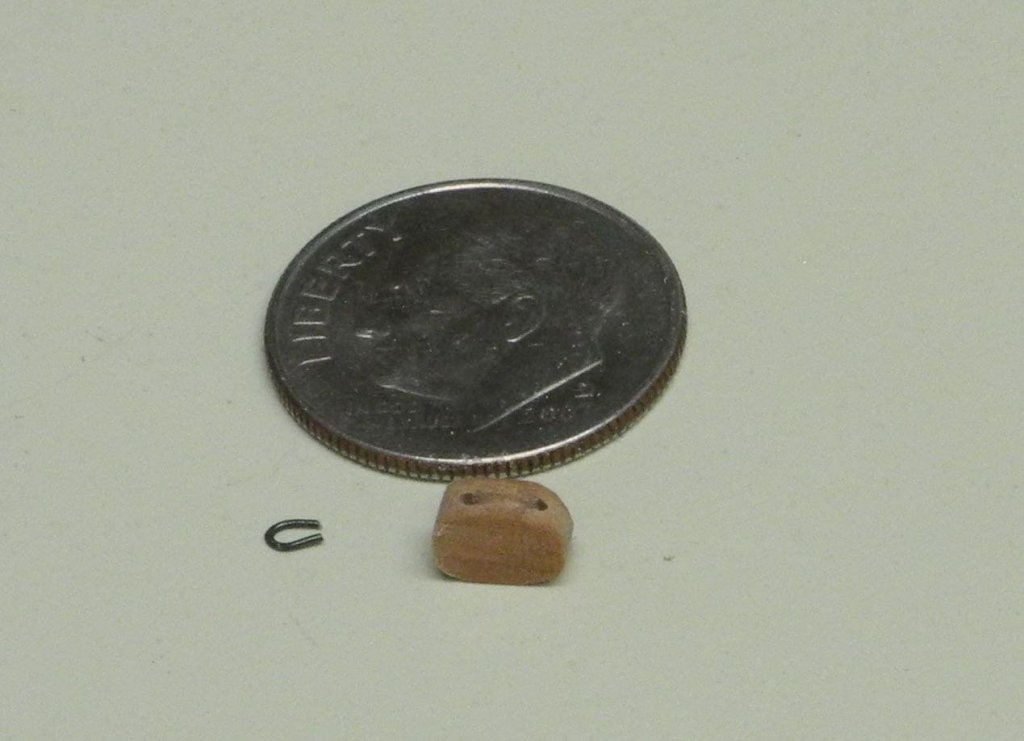
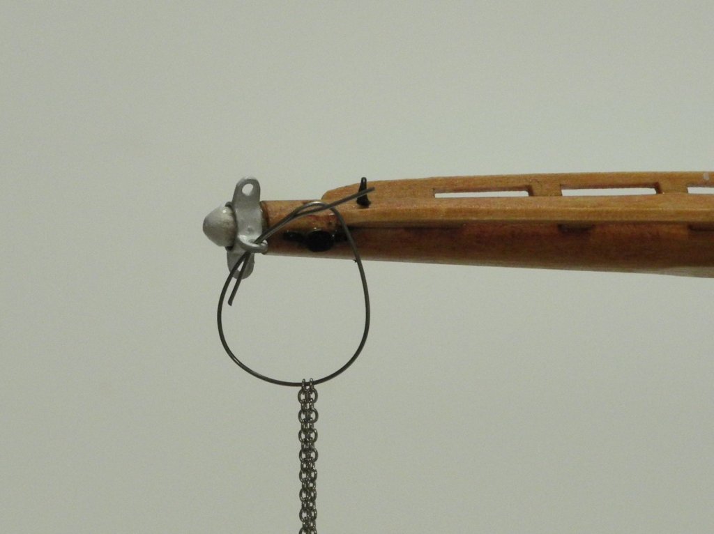
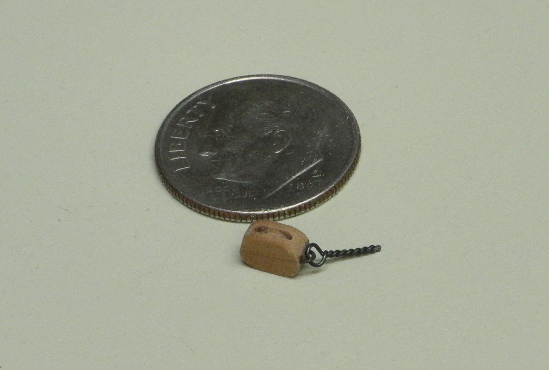
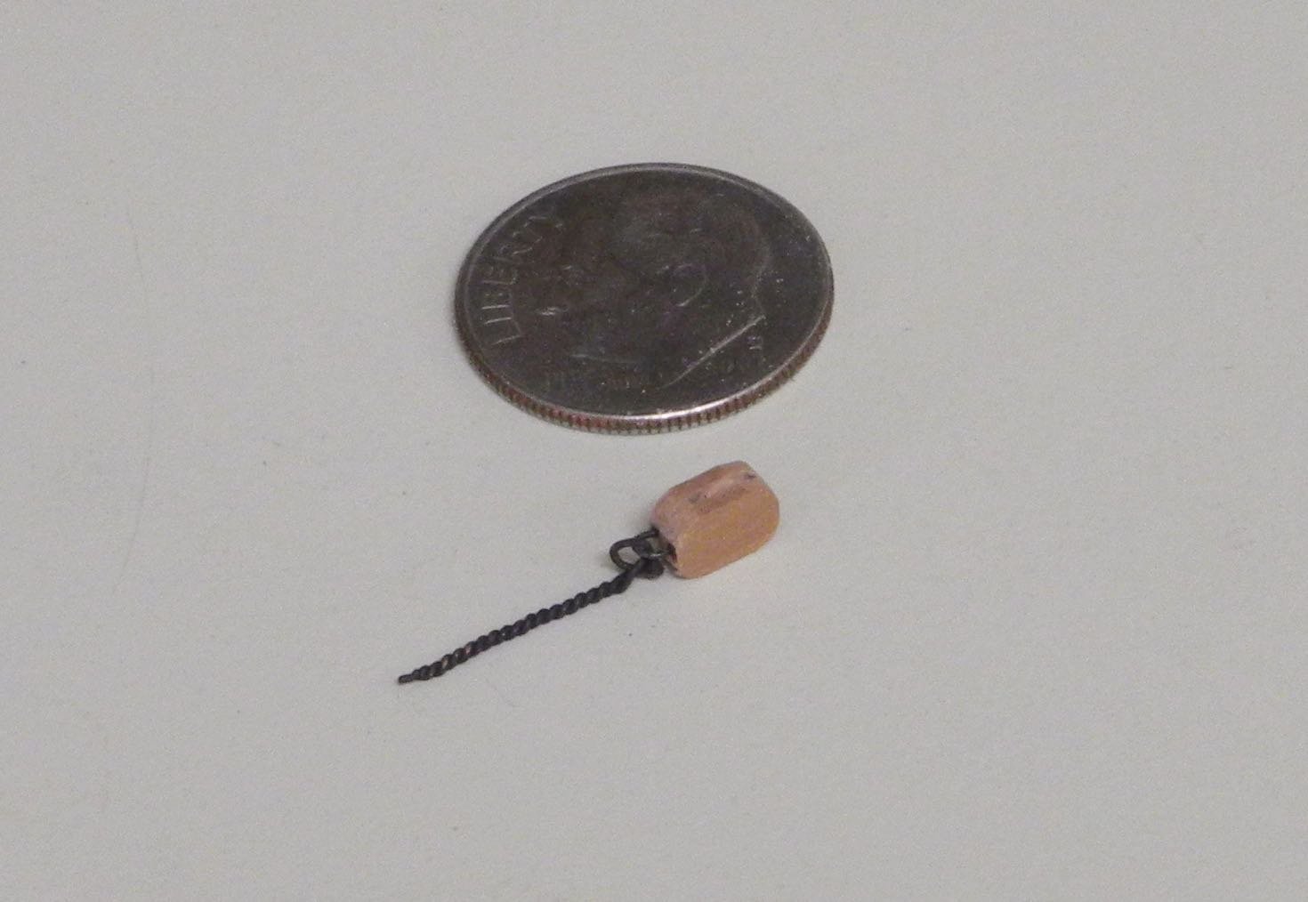
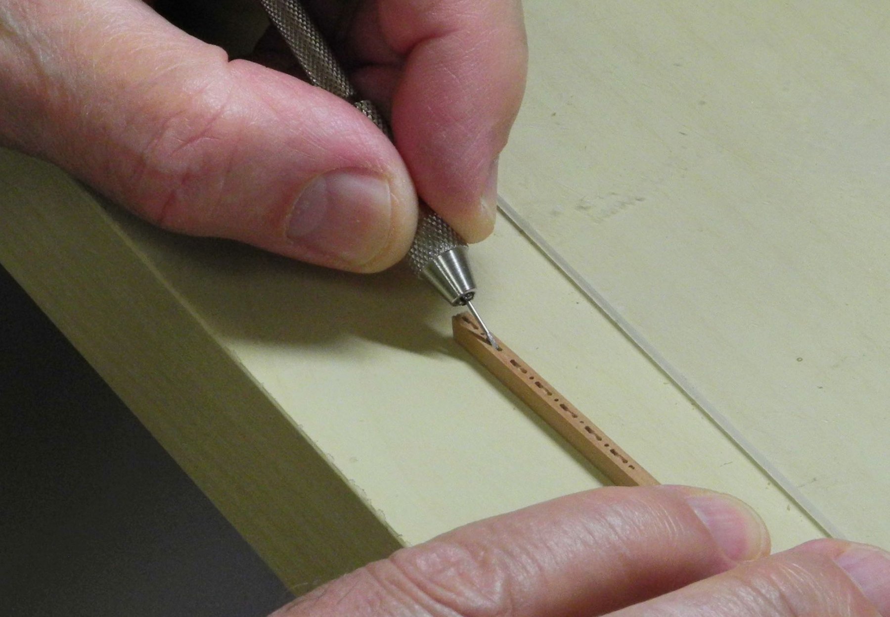
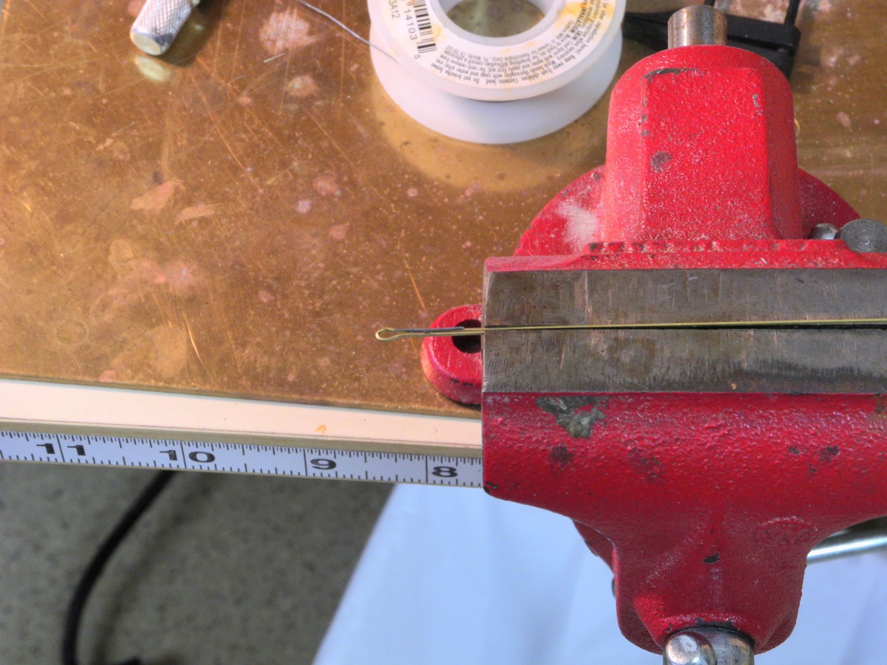
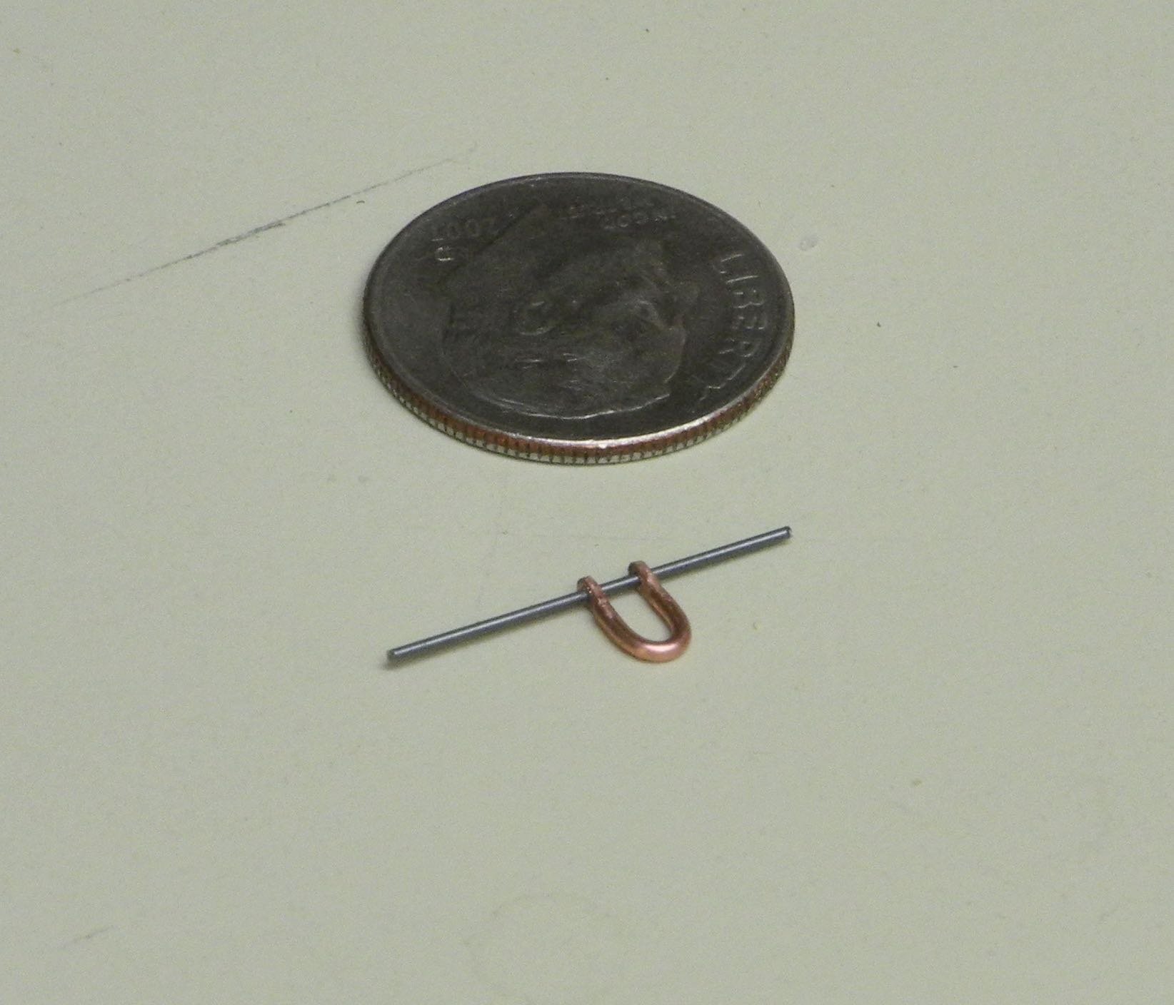
Adding a ring to Kathryn’s single blocks required a different approach than simply adding a ringbolt. The single blocks did not have very much wood above the sheave slot, so a ringbolt set into that area would be fairly fragile. I decided to make holes on each side of the sheave slot and then to embed a wire that had been bent to a “U” shape.
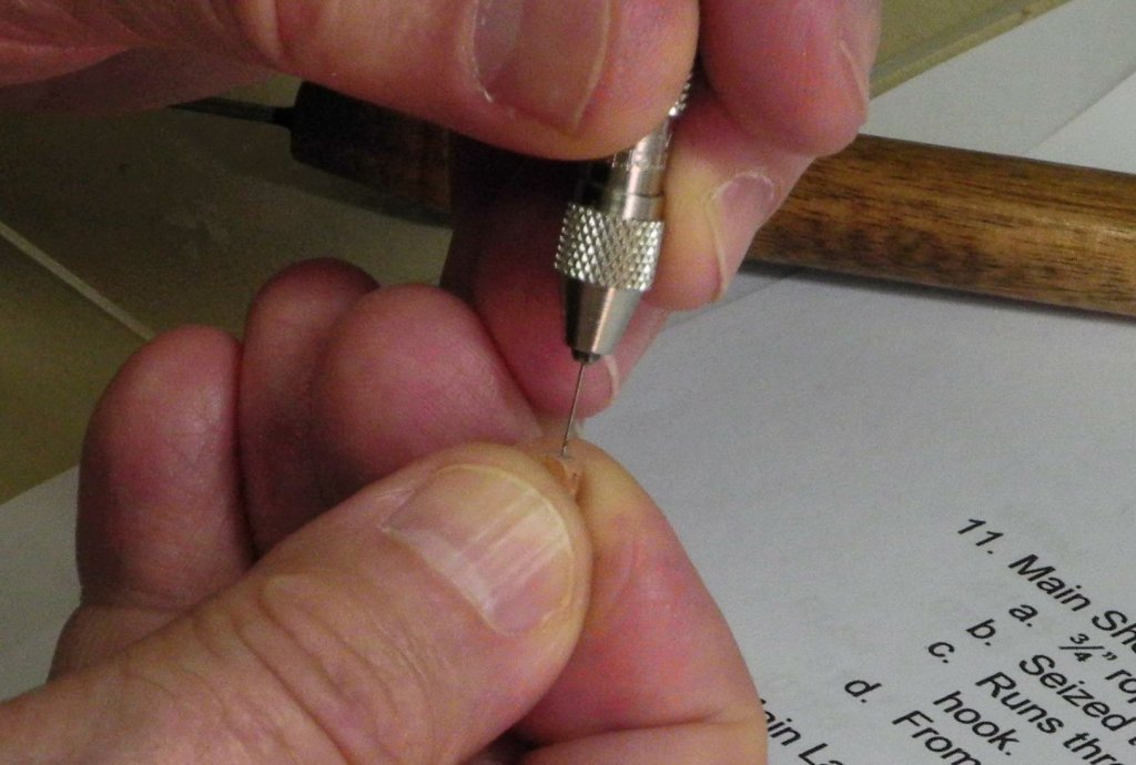
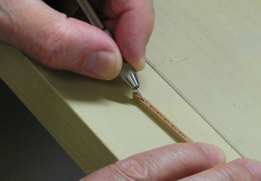
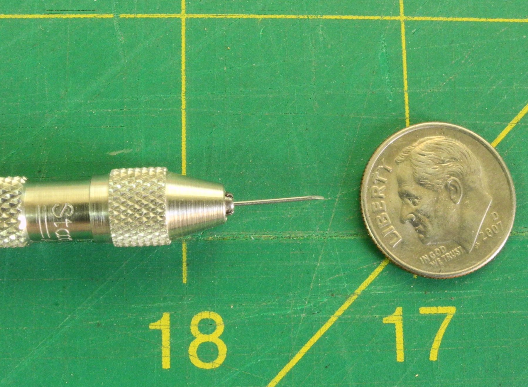
The first step was to make pilot holes using a small awl.

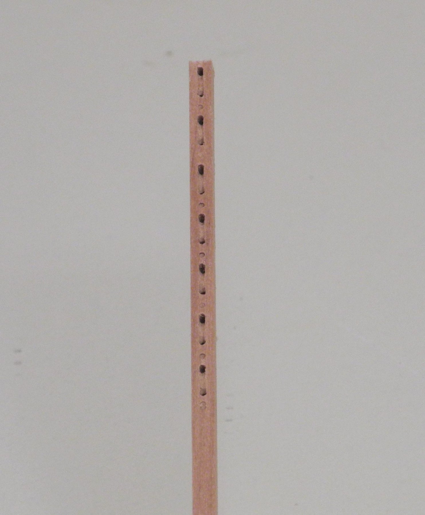
The holes were then drilled out by hand.
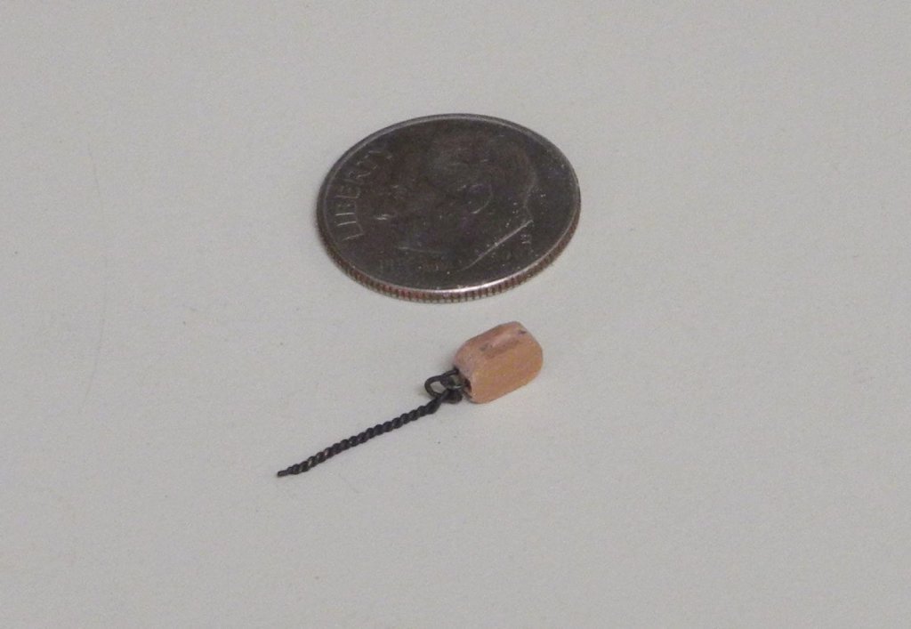
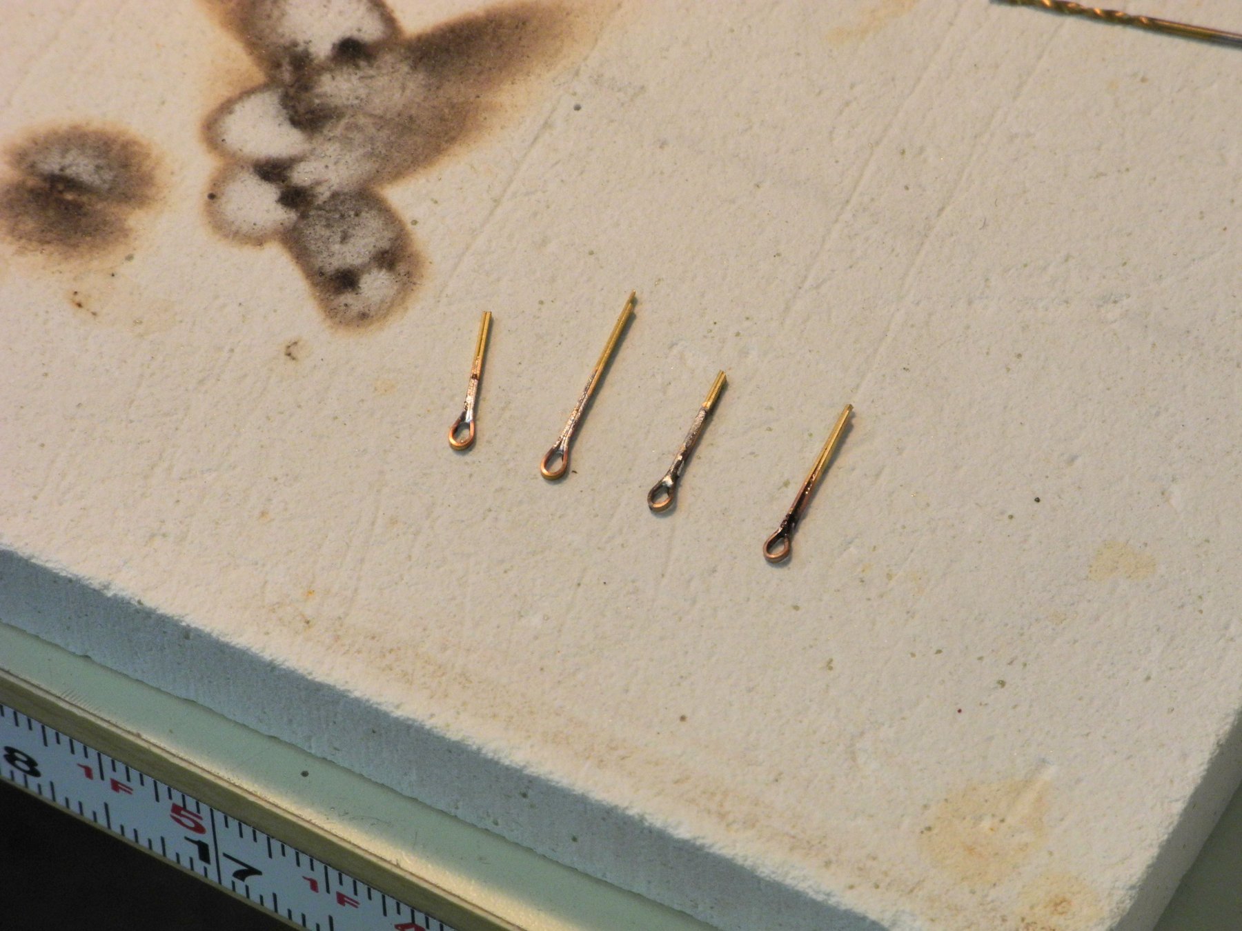
The wire loop was shaped and then CA-glued into the holes.

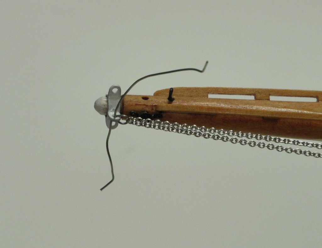
If a ringbolt was required to install the block, then the wire for the ringbolt was run through the loop and then was turned into a ringbolt.

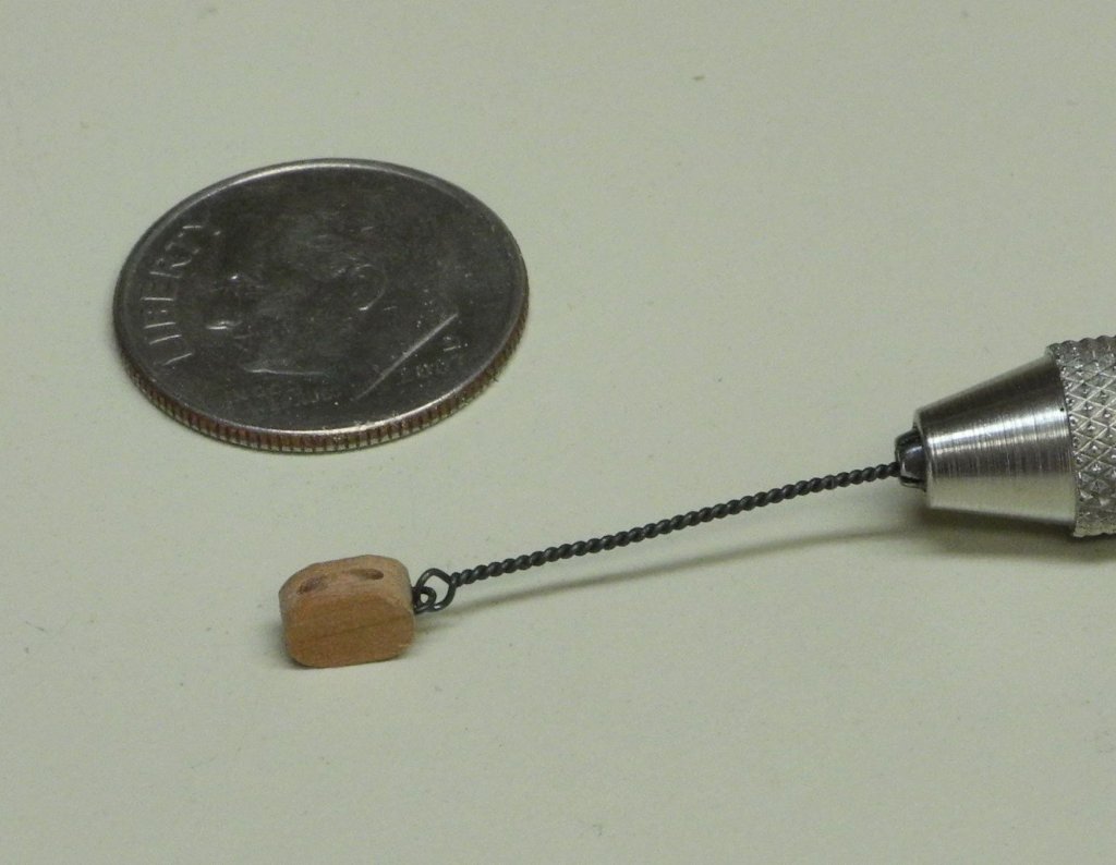
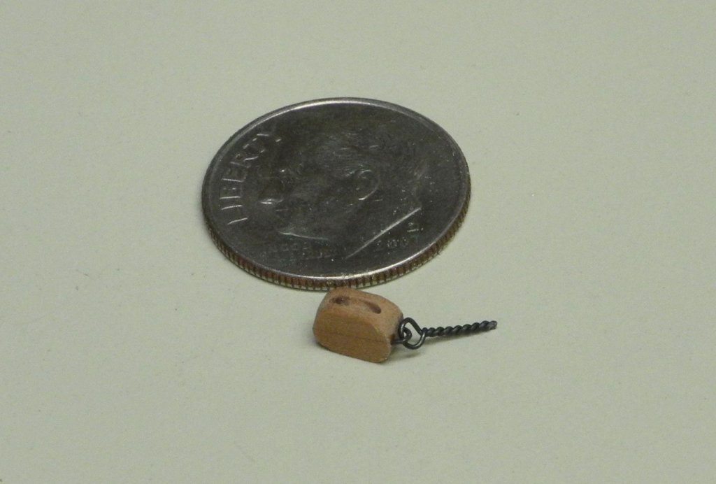
In the cases where a shackle was used to connect a block to a ringbolt, a shackle/ringbolt combination (prepared in Part 67) was added to the ring before it was installed in the block.
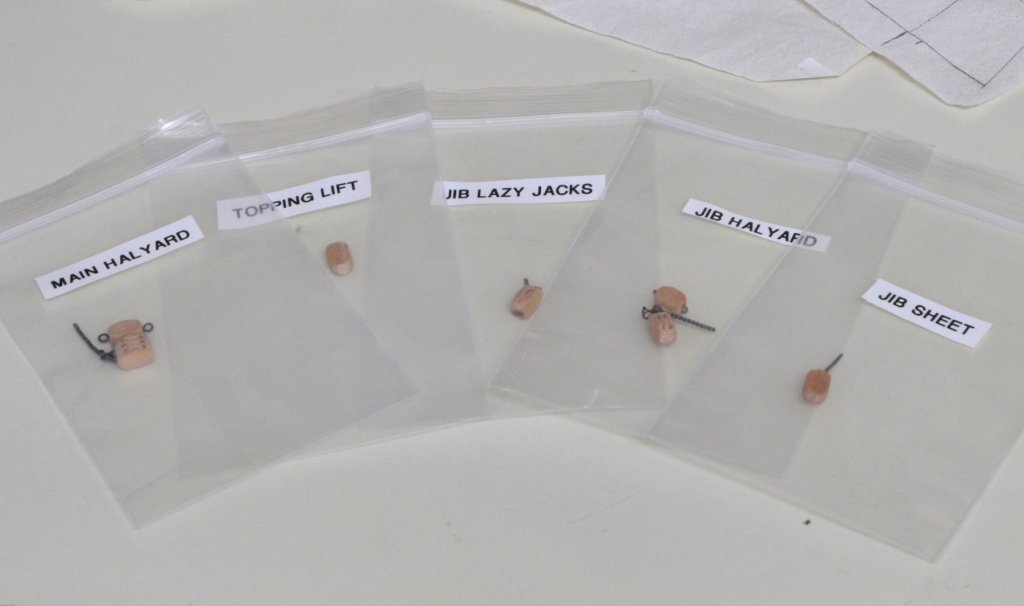
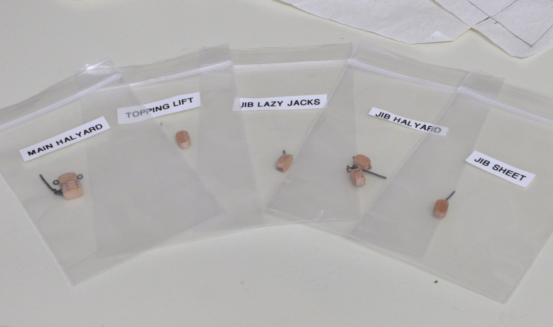
Each of the blocks required for a particular part of the rigging was completed and then filed away in a small bag marked with its destination.
Now it’s time to step the mast, which will be the subject of the next post.
- thibaultron, hexnut, Omega1234 and 12 others
-
15
-
Thanks Druxey. Yes, that would have been easier (and smarter) than the way I made the blocks. I didn't leave enough room between the blocks to do it your way, but I will next time!
-
36 minutes ago, EdT said:
Catching up again, Frank. Love the meticulous attention to detail - and the methods. Bravo.
Ed
Thanks Ed. Always good to hear from you.
-
Part 77 –Blocks
Work on Kathryn has slowed over the last few weeks, due to travel and some chores that needed to be done. What time I have been able to spend on Kathryn has been devoted to learning how to make and furl sails made with silkspan, and in reviewing the details of Kathryn’s rigging.
Blocks have already been installed for the main sheet and jib sheet – those were internally stropped Syren blocks. I decided to make the required additional seven blocks from scratch. These are all 5” blocks: 1 triple, two doubles, and four singles.
After shaping the required stock, top and bottom sheave holes were drilled for each block using a #70 drill. A slight indent (which I call a boundary hole) was also drilled at the point between the blocks. In previous attempts I had drilled these holes completely through the blocks so that the blocks could be cut from either side, but I found that the remaining groove from the hole required me to take too much stock from the block and changed the block’s dimensions.
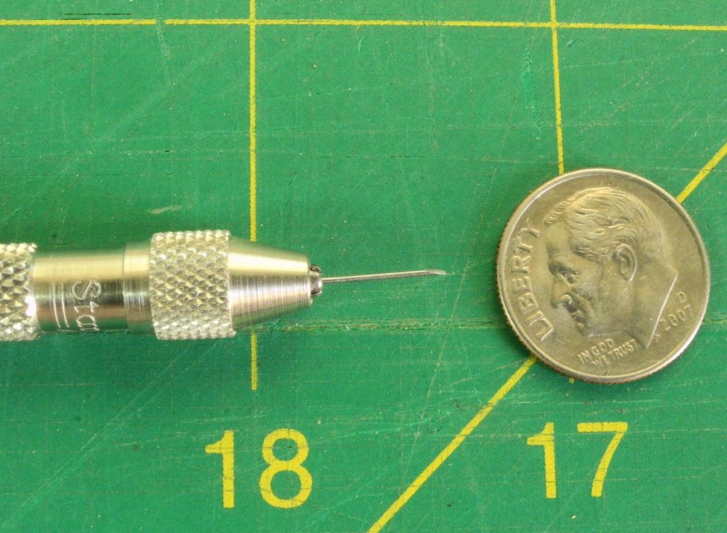
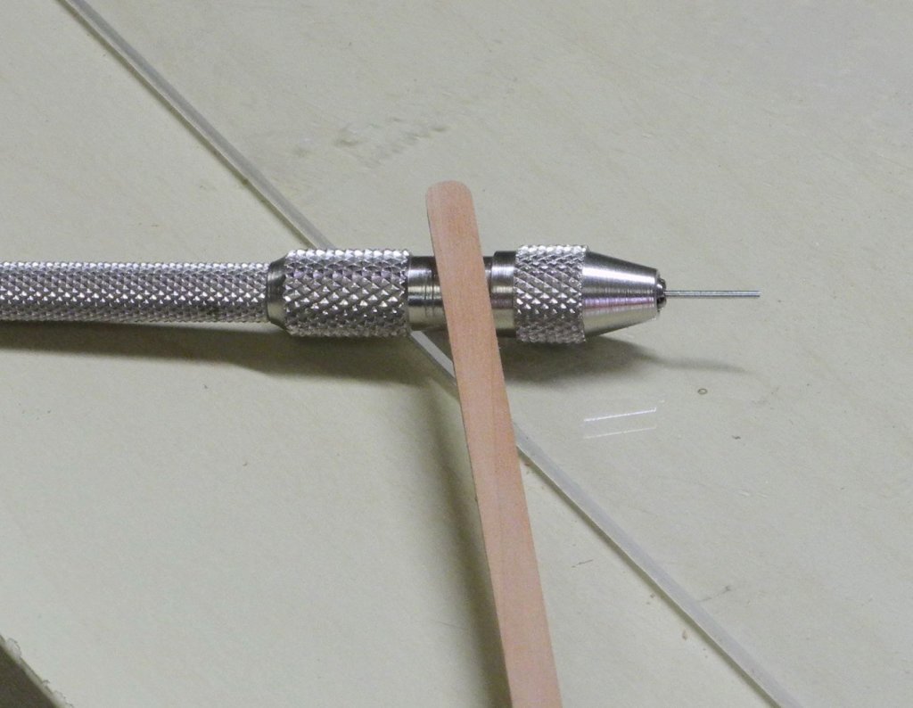
Rather than milling the grooves for the sheaves, as was done for the large triple blocks supporting the yawl boat, these grooves were cut using a small chisel that had been made by grinding the blank end of a #70 drill bit. The following photo shows this chisel held in a small pin vise.
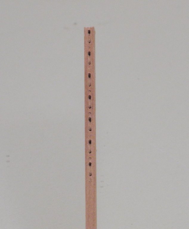
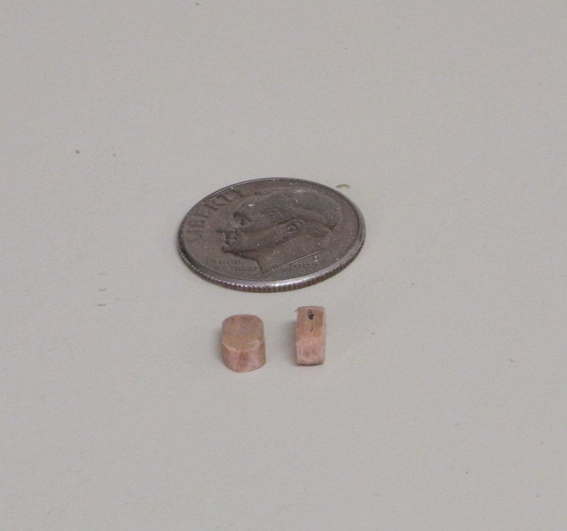
The following photo shows the stock for single blocks drilled and then shaped for the sheaves. Shaping the sheaves allows the rigging line to lay more realistically in the blocks.
Before separating a block, the outside end was rounded using a sanding stick.
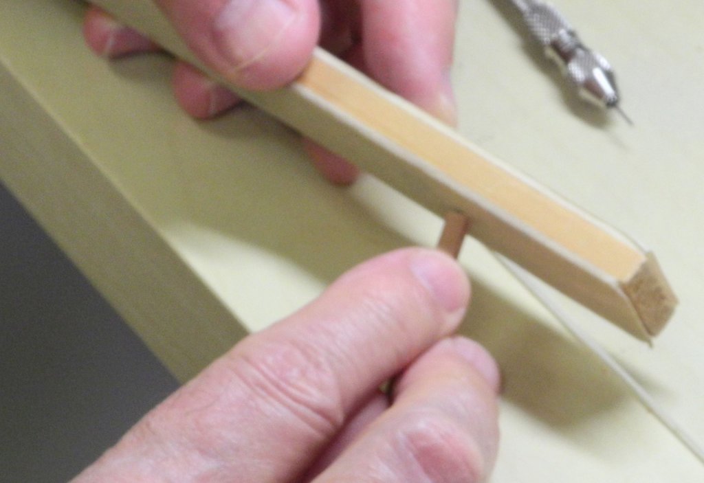
The block was then parted off.

Then the other end of the block was rounded while held in a small pliers.

The small number of blocks allowed me to finish this effort relatively quickly, even though it was fairly labor-intensive.
The blocks will need some added hardware, which will be the subject of the next post.
Cheers, everyone.
- mtaylor, HIPEXEC, thibaultron and 13 others
-
16
-
-
-
9 hours ago, michael mott said:
Frank you have done a superb job of matching up all the stays on the bowsprit.
Michael
Thanks Michael - having good reference material really pays off.
45 minutes ago, druxey said:A very instructive series on metal rigging work! Thank you for sharing your techniques, Frank.
Thanks Druxey - it has been a good learning experience for me also, having never done this type of work before. I've learned a lot of the different techniques from watching EdT's work.
-
On 7/20/2018 at 9:05 PM, mtaylor said:
You should be more than pleased, Frank. I had to really look twice to sort out model from real. Beautiful work on that rigging.
Thanks Mark. Each stay had to be reset several times to get the tension right. The use of 'simulated shackles' really helped out in doing this. I could see if the chain was too tight, or too loose, before tightening the 'shackle' wire, and this allowed me to put another wire through a different link in the chain while the original wire was still in place.
9 hours ago, Calhoun Zabel said:Ditto what Mark said. You've even got the drop of the chains correct, to my eyes. Very impressive stuff. I look forward to following along as you complete this build.
Thanks Calhoun! I've been watching you moving through the log via all of your 'likes' - welcome aboard. Having seen Kathryn up close a couple of times, having lots of photos of her, some friends who know a lot about her, and of course the wonderful HAER drawings - all of this has helped me in trying to stay true to her appearance. I know I won't have these advantages for my next model, but this has been a great experience for me so far.
- mtaylor, Canute, thibaultron and 4 others
-
7
-
-
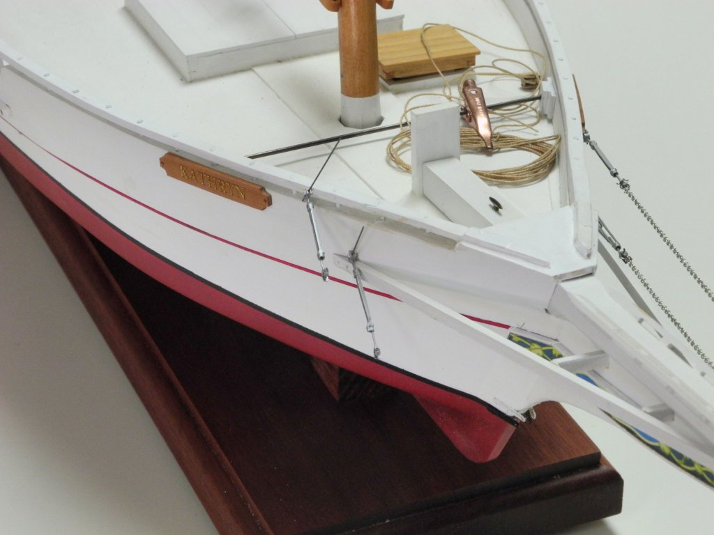
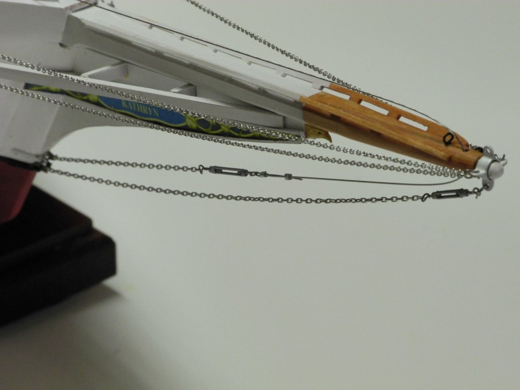
Part 76 –Bowsprit Stays
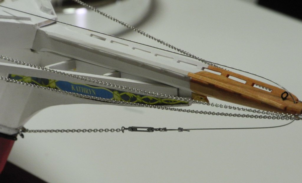
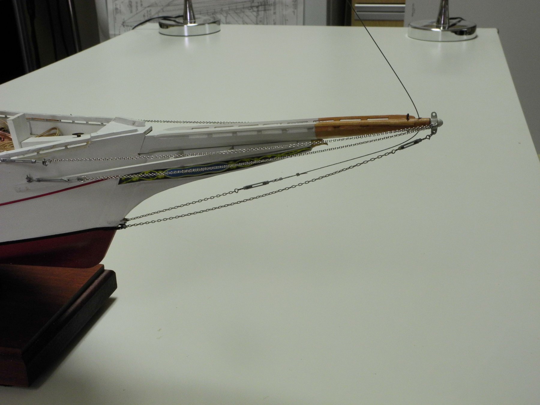
Kathryn has seven stays associated with the bowsprit.

There are four Jack Stays, 2 on the port side and 2 on starboard. These stays, made of chain, are connected to the port and starboard lugs on the bowsprit band and by turnbuckles to ringbolts at the railing and the wales.
The JIB Stay is a chain attached to the upper bracket on the outer stem, and the chain is connected to a steel cable by a turnbuckle. The cable runs through a hole at the end of the bowsprit up to the mast hounds.
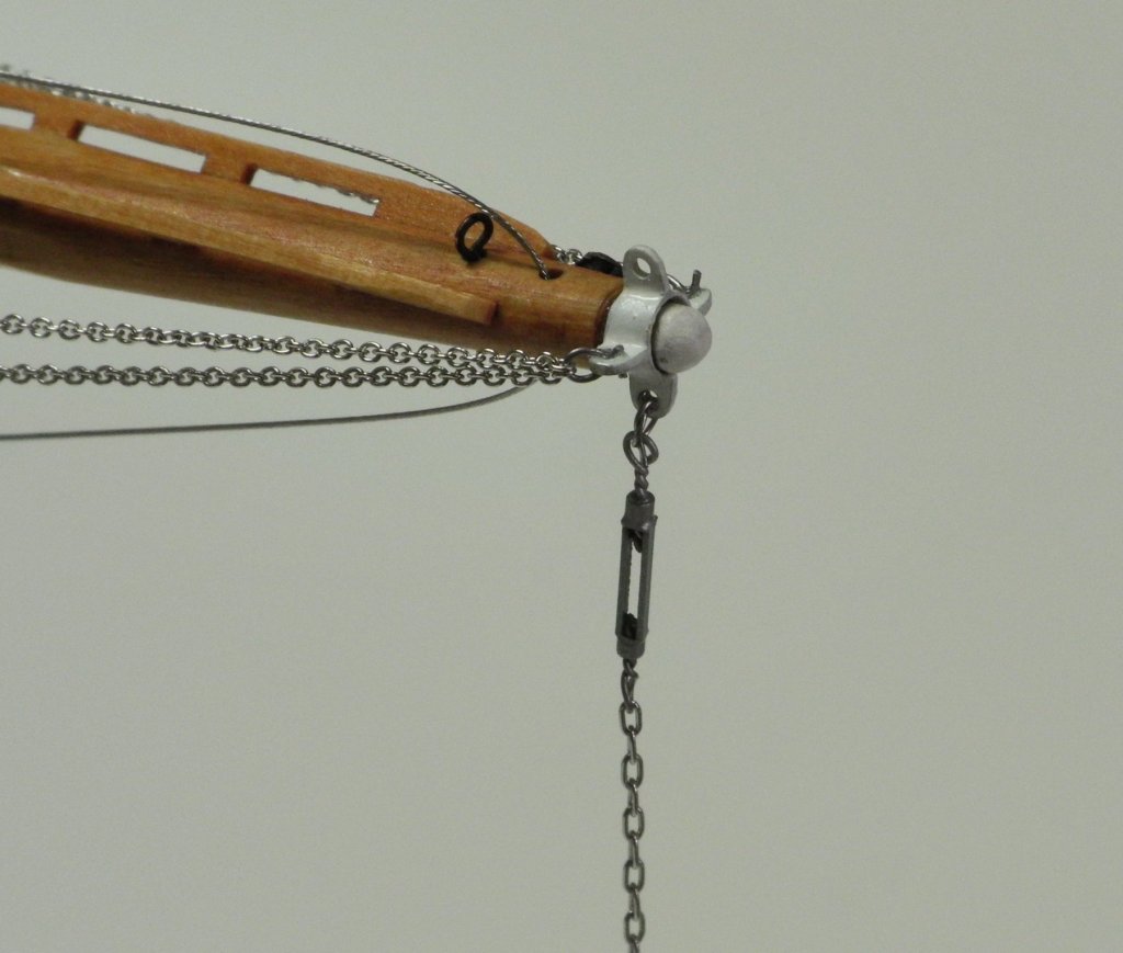
The Bob Stay is the lowest stay, is made of chain and is attached to the lower bracket at the outer stem. It is connected by a turnbuckle to the lower lug on the bowsprit band.
The Head Stay is a steel cable connected by a turnbuckle to the upper lug on the bowsprit band and to a shackle at the mast top.
I was able to find silver chain at Arrow Hobby.
https://ppw-aline.com/collections/tie-down-chain
The smallest silver chain is 27 links per inch, which worked for the Jack Stays, and the larger chain used for the Bob Stay and Jib Stay is 15 links per inch.
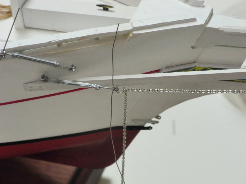
The Jack Stays were installed first. Installation began by installing the required ringbolts and painting them to match the hull.

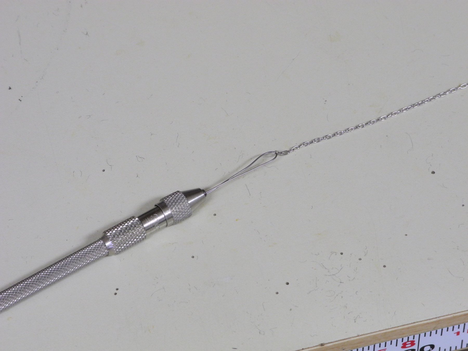
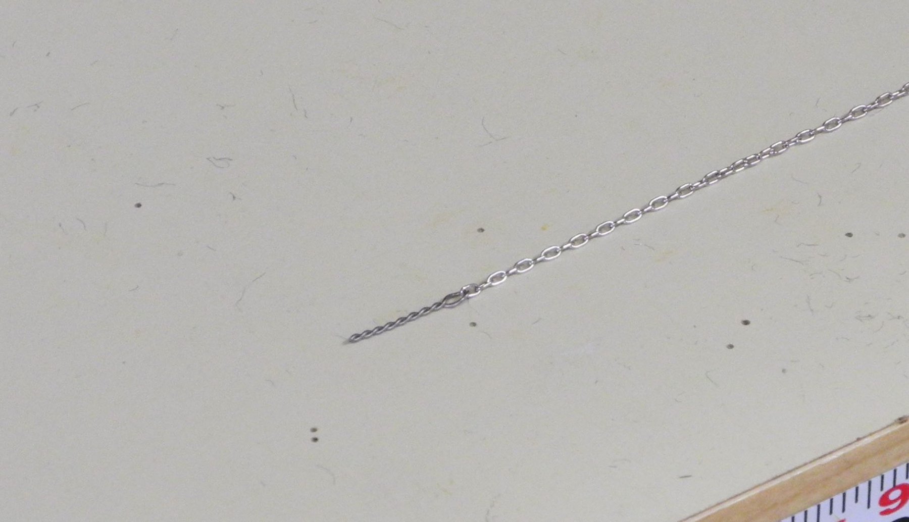
Shackles for the stays were simulated by tying nichrome wire to the connection points. Nichrome wire has a silver color which blended well with the chains and turnbuckles. A loop of 26 gauge nichrome wire was passed through the end links of two lengths of 27 link per inch silver chain and then tied in a knot which was located behind the lug on the bowsprit band.
When the loose ends were clipped off the wire loop simulated a shackle.
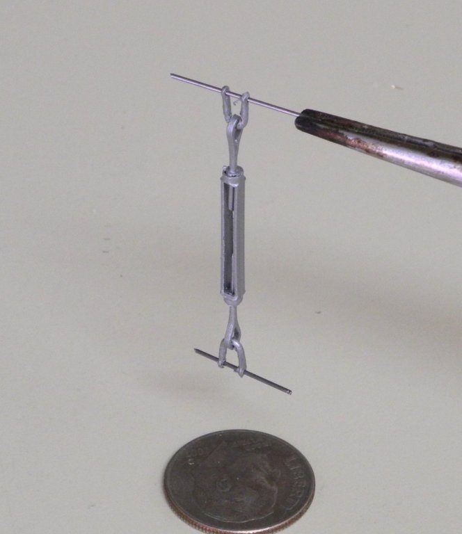
Piano wire was used for the connecting pins because of its strength. The turnbuckles for the Jack Stays were attached to the ringbolts by short lengths of .014 steel piano wire run through one hole of the turnbuckle’s clevis, through the ringbolt, and then through the other hole in the clevis. The piano wire was epoxied in place and then clipped off when dry.
A short length of piano wire was glued into the holes at the other end of the clevis prior to the turnbuckles being mounted. A loop of 28 gauge nichrome wire was used to form a shackle tying the Jack Stay chain to the turnbuckle around that short length of piano wire.

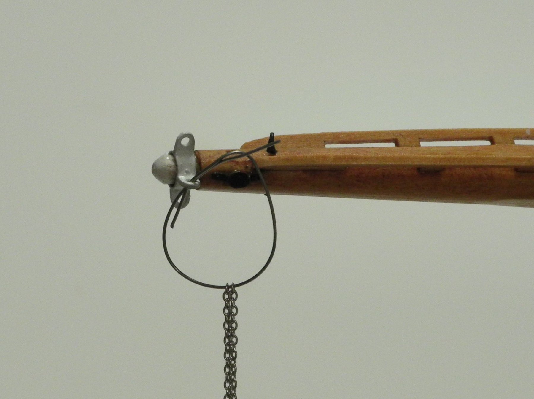
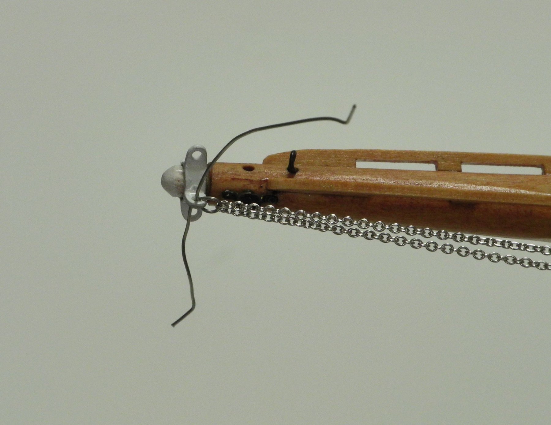
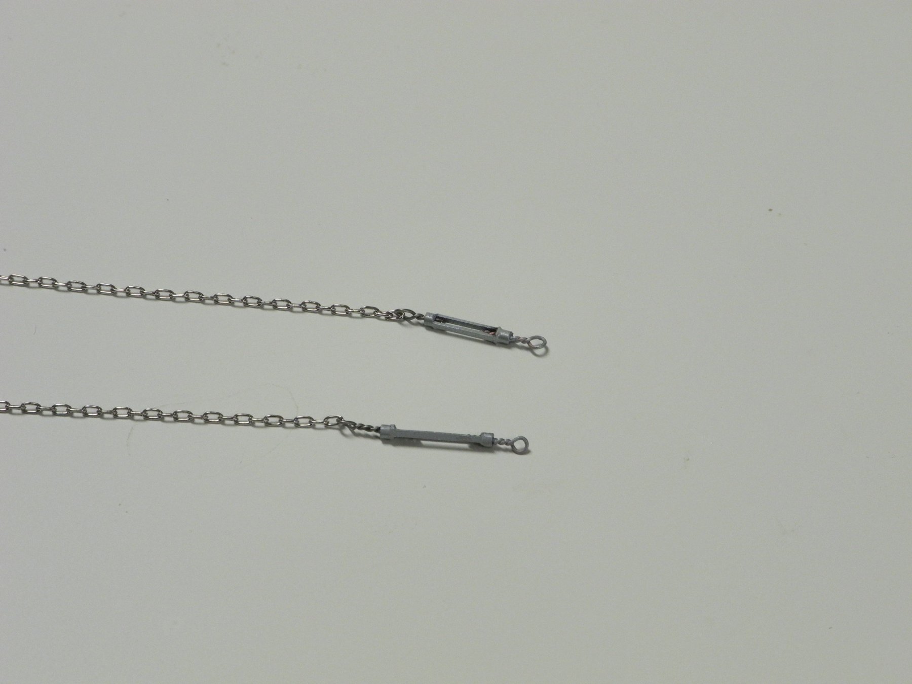
The Jib Stay and Bob Stay both have the chains attached to a ring on a turnbuckle. The turnbuckles used for these stays were initially made with only one ring each. The second ring was formed of nichrome wire which had first been run through the end link of the associated chain, as shown in the following sequence.
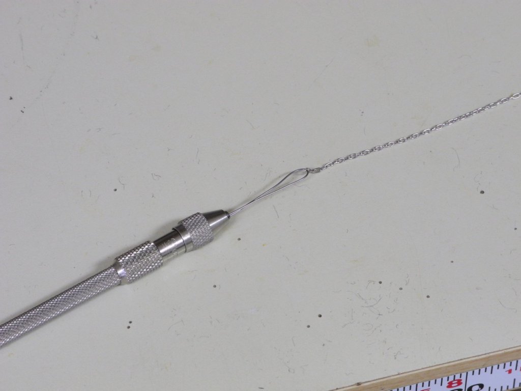
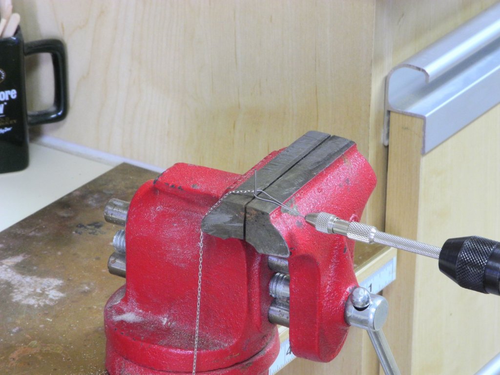
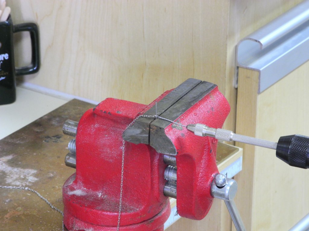

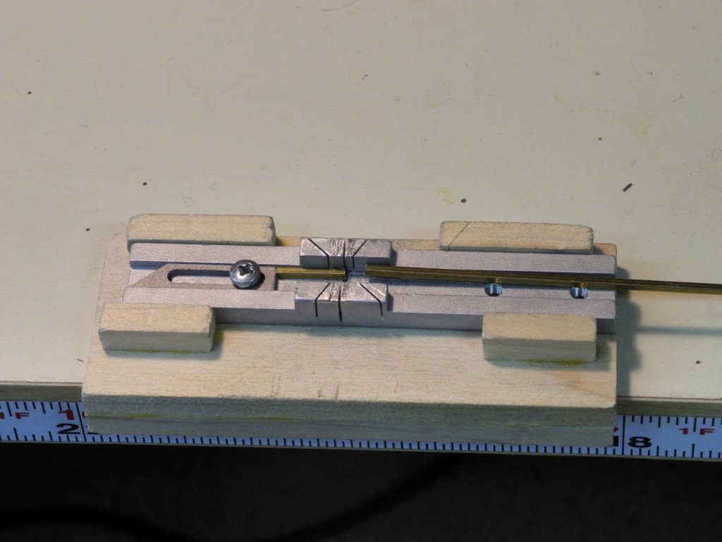
These ring/chain combinations were then epoxied into the turnbuckles.
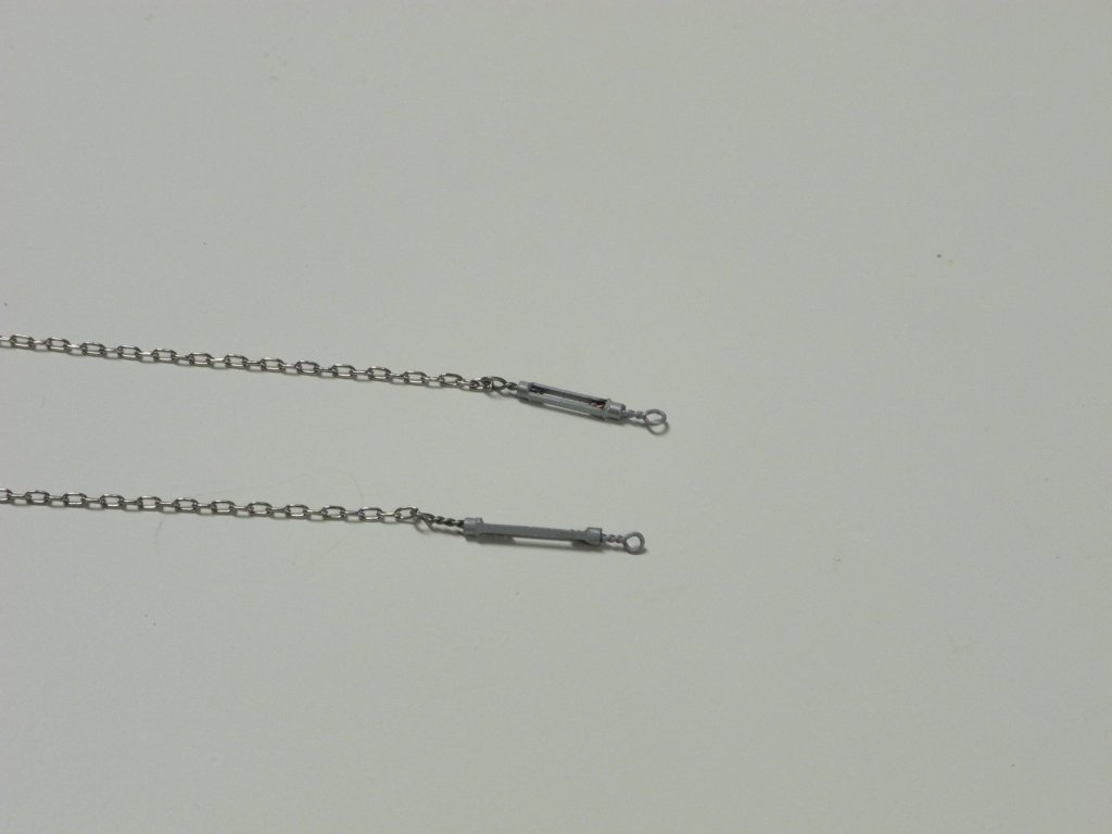
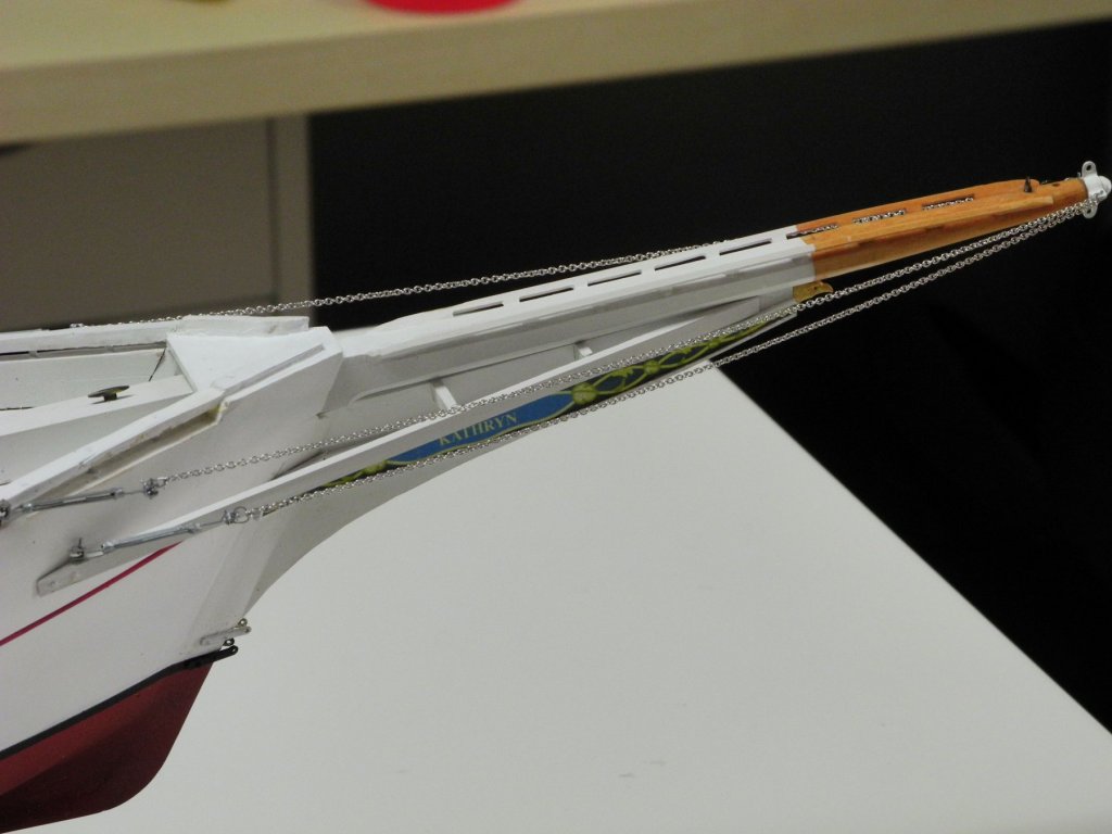
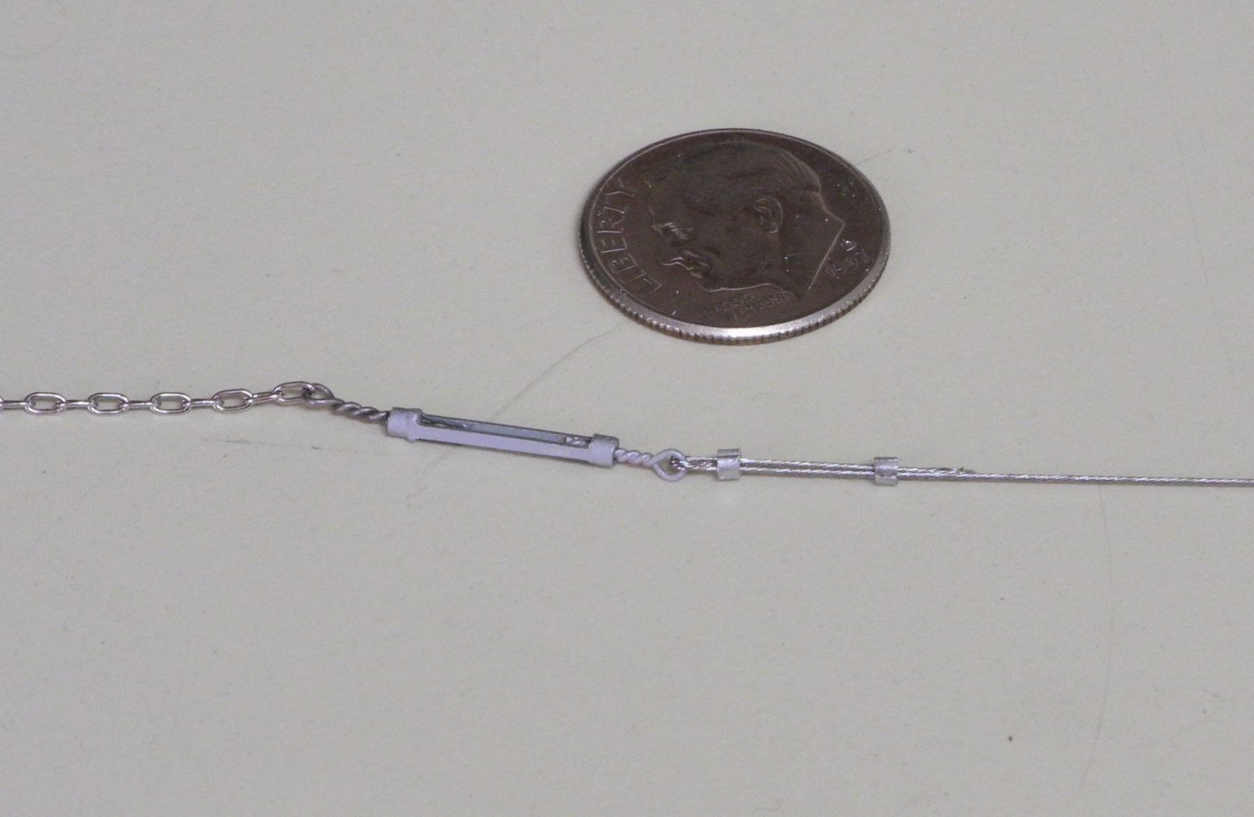
The Jib Stay was installed next. The first step was connecting the steel cable to the turnbuckle. The ‘steel cable’ was made from .014” bare leader wire from AFW fishing.
https://afwfishing.com/afw_products/Surfstrand_Micro_Ultra_Leader_Wire_Uncoated_1x19.asp
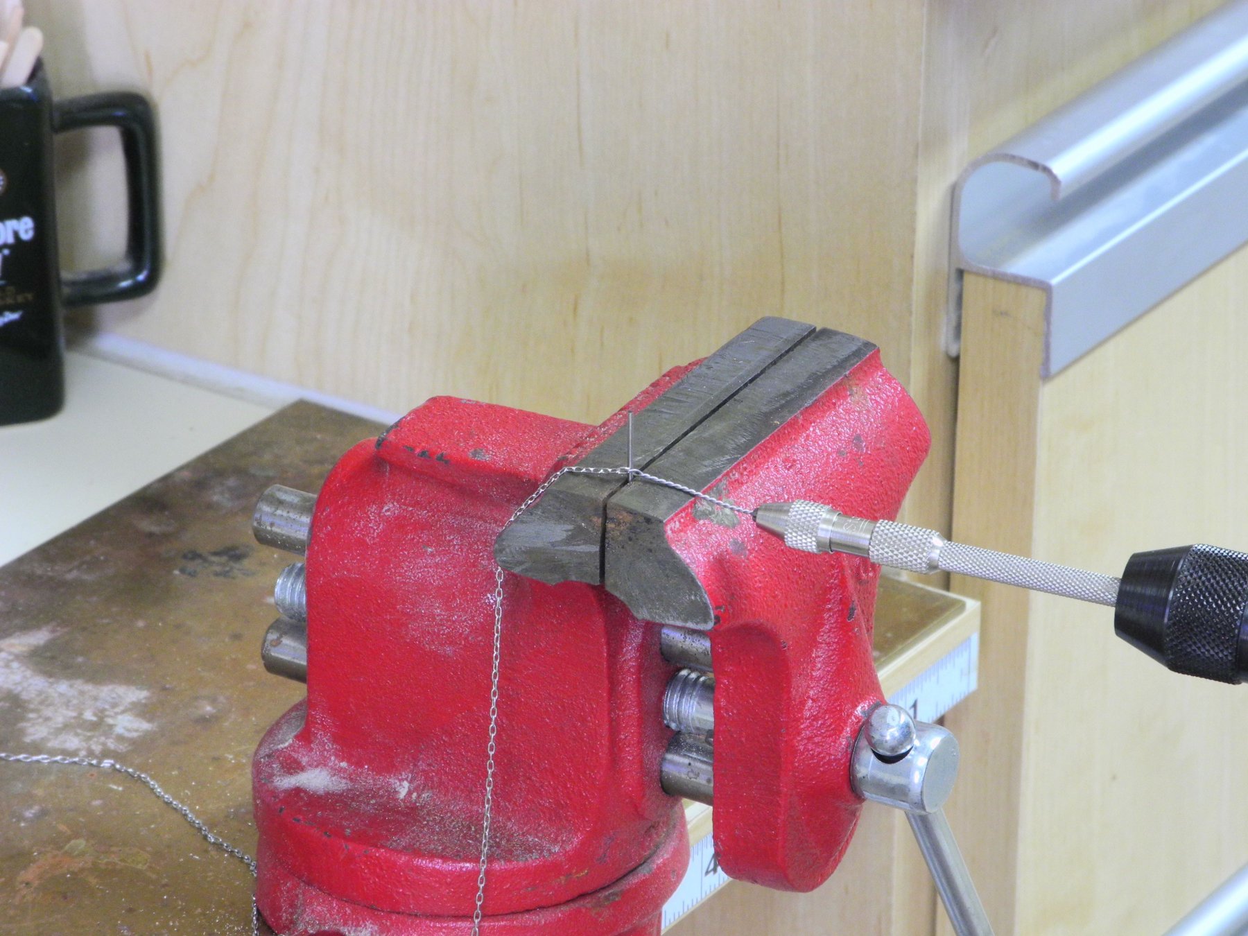
Crimping tubes were made by cutting small pieces off a 1/16” aluminum tube.
The wire was passed through two of the crimping tubes, then through the open ring of the turnbuckle, and then back through the crimping tubes. It was then crimped and trimmed.
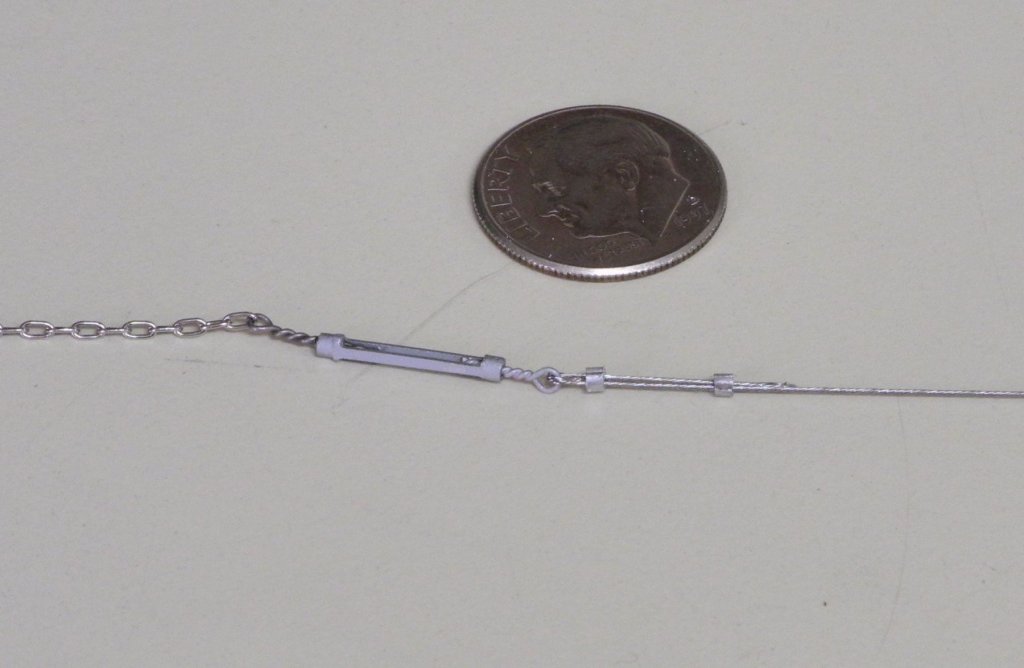
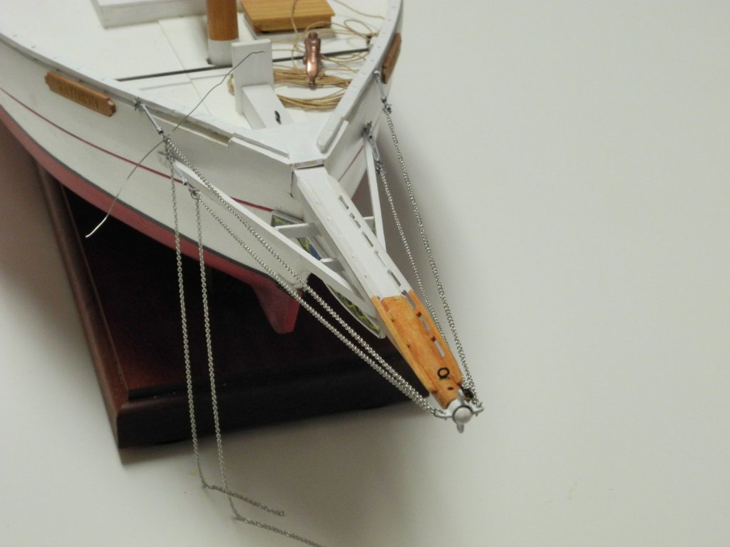
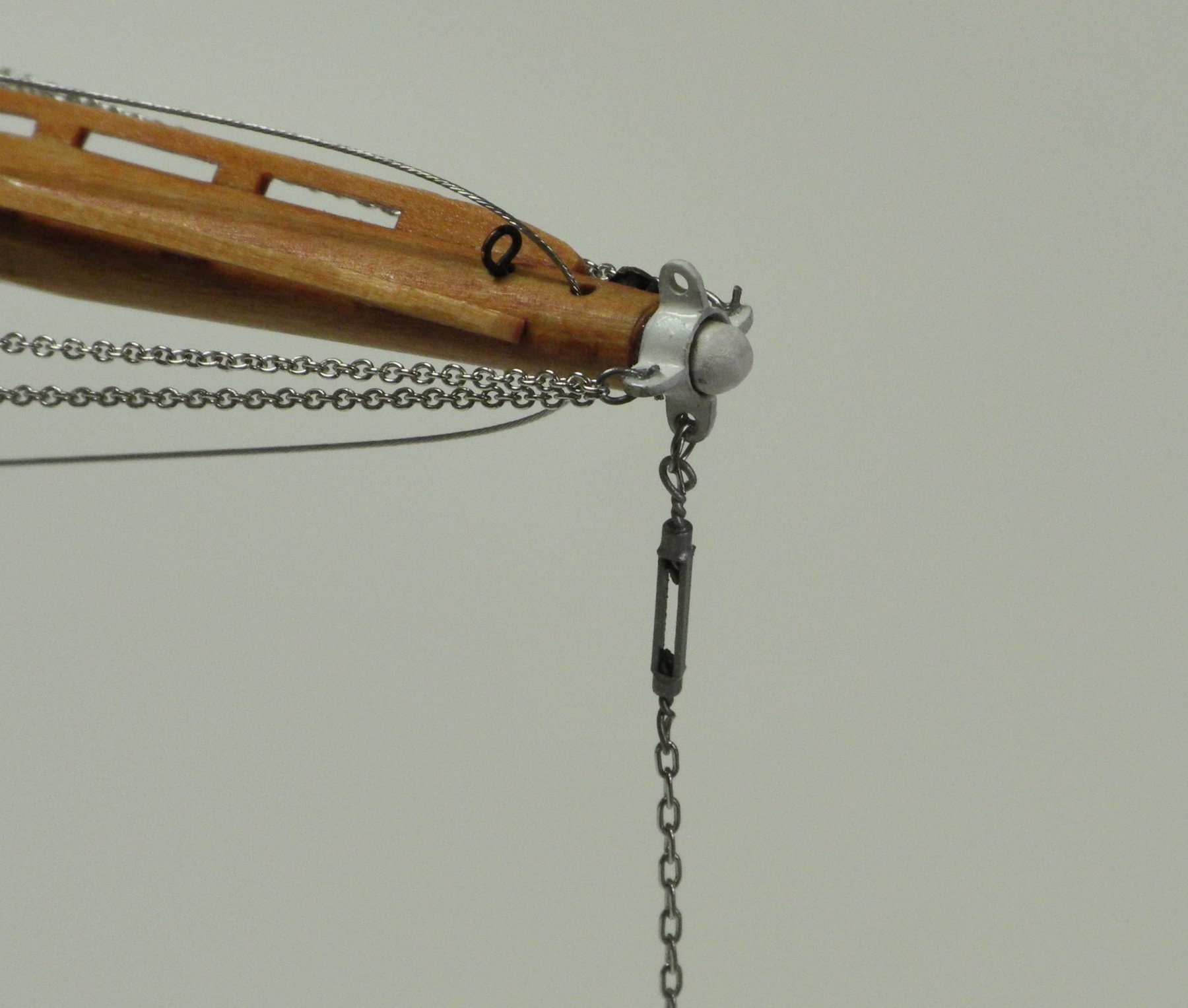
The wire was passed through the hole in the bowsprit, and then the chain on the other end of the turnbuckle was ‘shackled’ to the upper bracket on the outer stem using 28 gauge nichrome wire.
The Bob Stay turnbuckle was ‘shackled’ to the lower lug on the bowsprit band, and then was ‘shackled’ to the lower bracket on the outer stem.
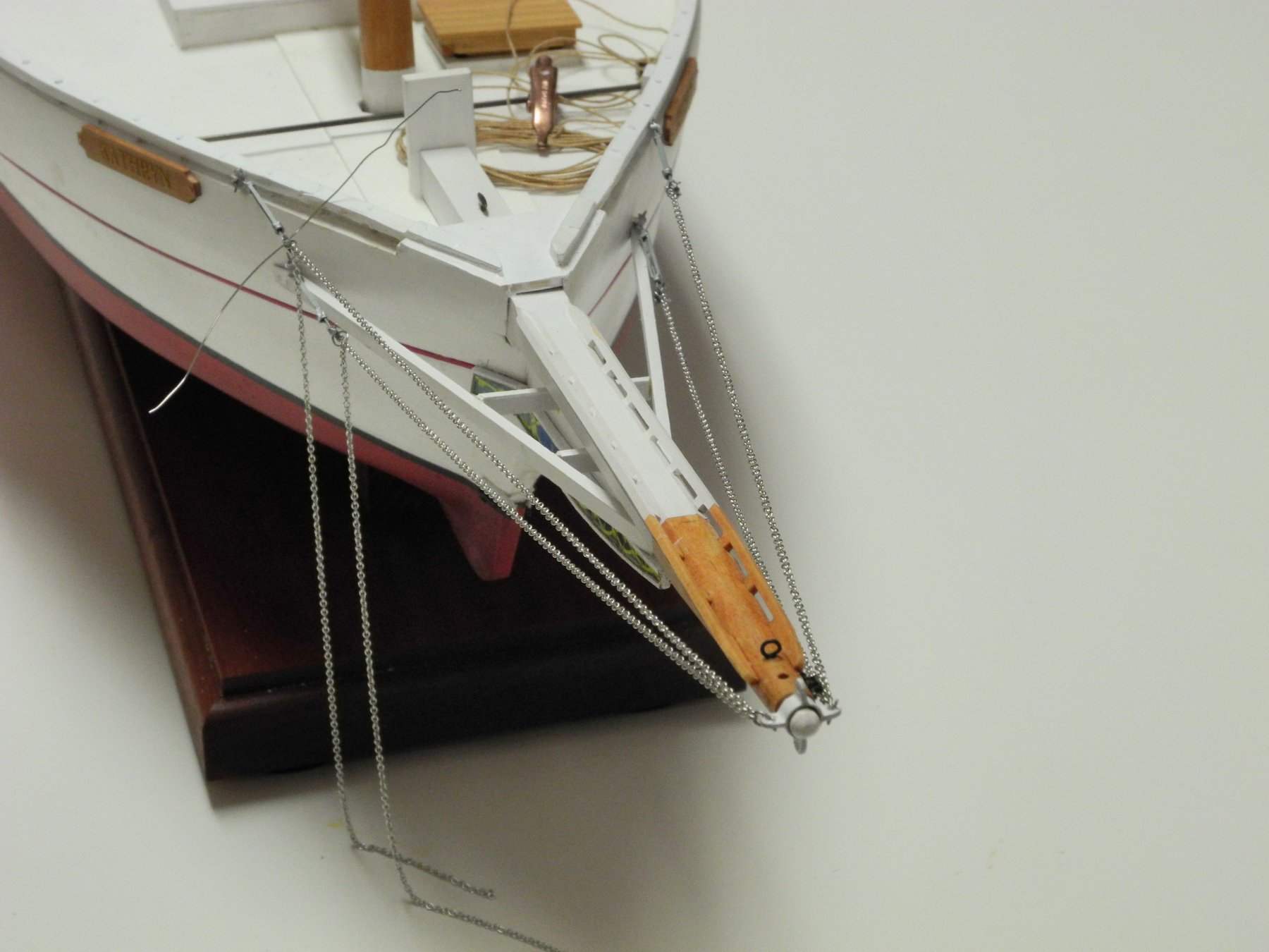
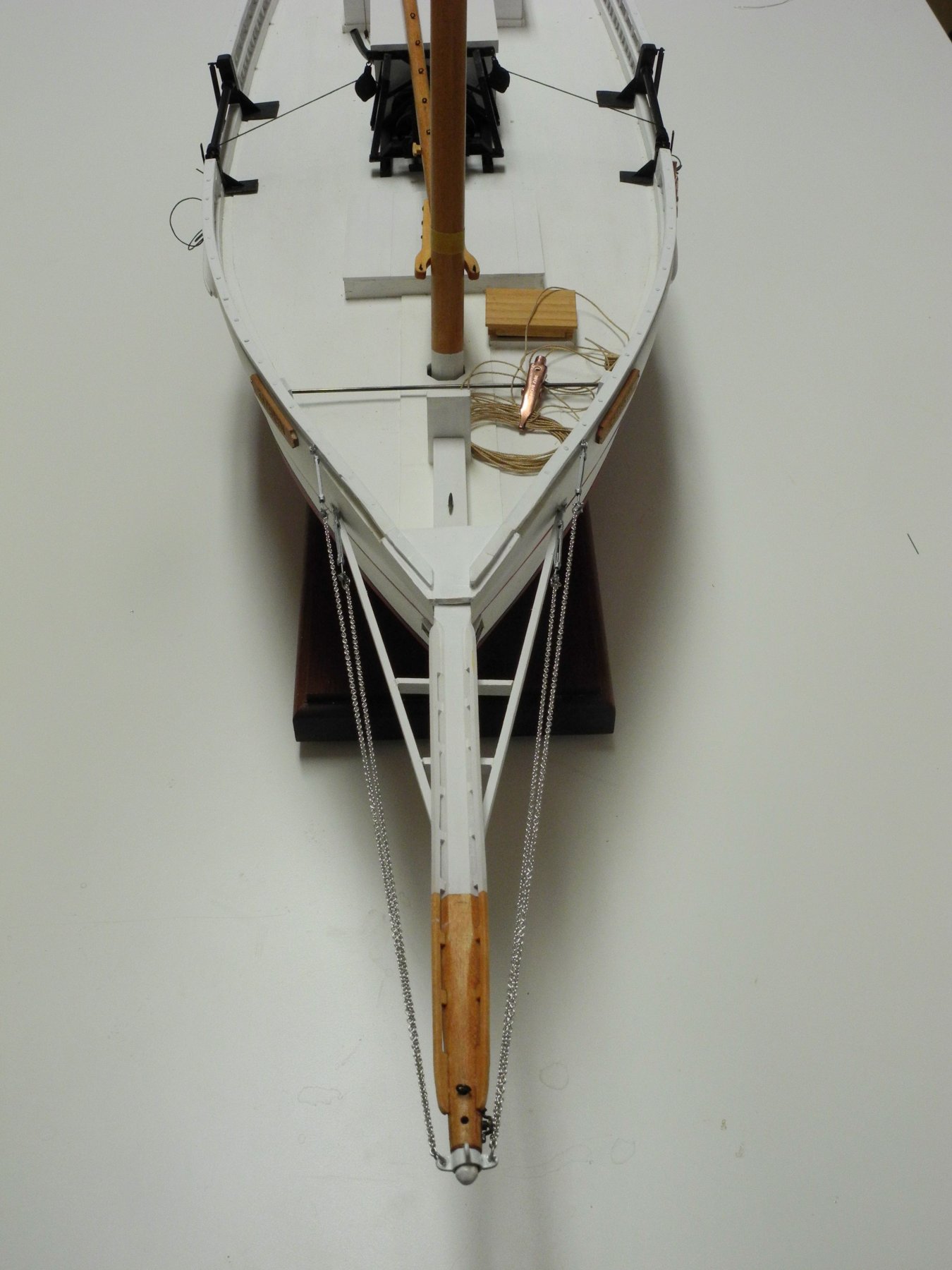
This completes the bowsprit stays for now – the Head Stay will be installed at a much later time in the rigging sequence.
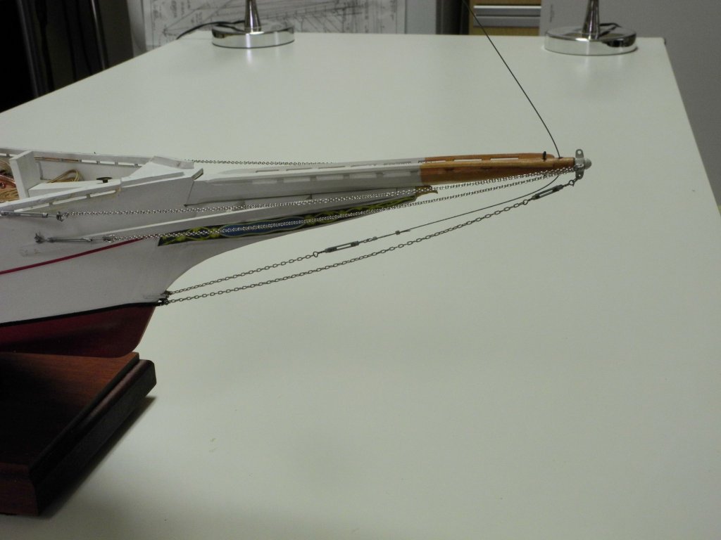
I’m pleased that these stays match up pretty well to the photos of Kathryn’s bowsprit area.
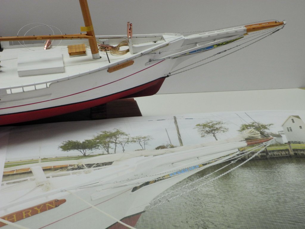
This will probably be my last post for a while. I’ll be spending time experimenting with the use of silkspan to make furled sails. I’ll also be spending some time planning the rigging sequence. We’ll also be taking a short vacation to get out of Arizona’s heat – unfortunately that little trip is still over a week away, and our forecast for the next few days is VERY HOT – up to 117F!!
Cheers everyone!
-
10 hours ago, michael mott said:
I think that is why jewelers and watchmakers tend to have a smock connected to the bench to catch those parts. I of course would forget that I was attached and get up and pull the whole bench over
Hi Michael - yeah, I've thought about doing this. But like you, I tend to move around the shop a lot and would probably cause more problems than I solved with the smock.
4 hours ago, cog said:No pivoting parts ... nicely stuck together with CA ... probably not a pretty sight either
Carl, I told you a million times not to exaggerate!

-
9 hours ago, michael mott said:
Nice work Frank.
Michael
Thanks Michael.
9 hours ago, cog said:Who would have expected that ...?
Very lovely turnbuckles, I am astonished by what you accomplish at that scale, and most of all the number of parts you can make separately. I would be happy if I could make it as a single piece!!!
Thanks Carl. I can't imagine how I could make these turnbuckles as a single piece! One of the problems I have is losing these small pieces to the floor, never to be seen again. I generally make extras for that reason.
-
Thanks Mark - I'm pretty happy with the way the turnbuckles worked out. Some of them are fairly delicate, though.
-
-
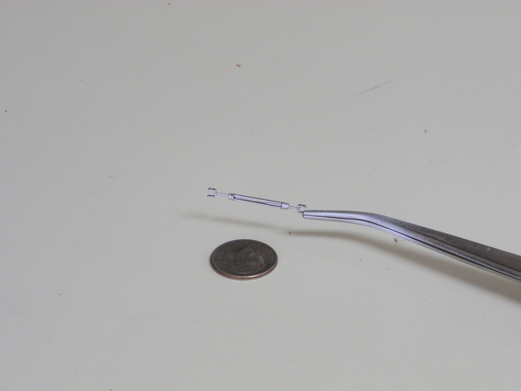
Part 75 –Turnbuckles cont’d
Kathryn’s shrouds are steel cable, and are held in place by large turnbuckles rather than deadeyes, as in the following photo.
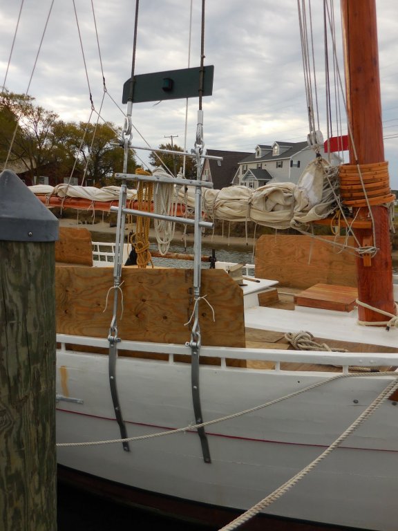
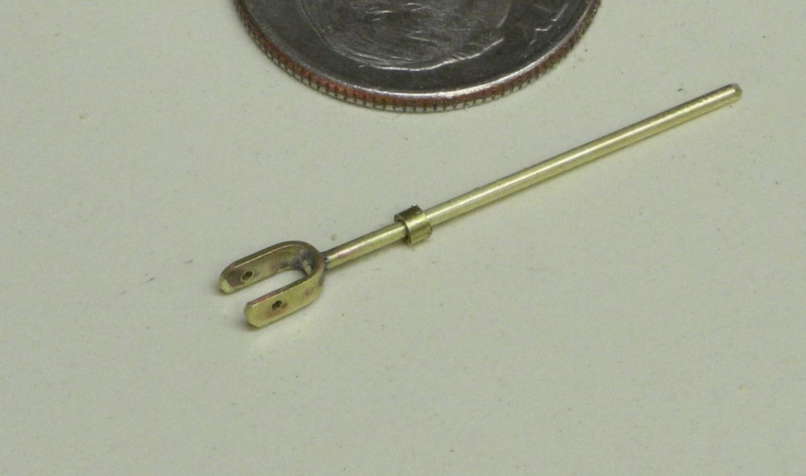
The connectivity consists of large loops at each end of the turnbuckle, connected by shackles to the chainplate at the bottom and to the cable at top. These large loops are made of flat stock which turns into a round rod so that it can be threaded to the turnbuckle.
My first thought was that this configuration would be too complicated to model, so I made some clevises on posts for connectivity to the turnbuckles.
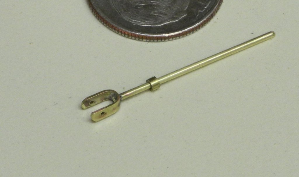
The small collar on the post is to provide a more secure fit to the turnbuckle. The turnbuckle bodies were made from 3/32” square stock which had a 1/16” round inside diameter. Since the posts needed to be smaller (1/32” rod) I drilled a 1/32” hole through a 1/16” rod and parted off sufficient collars for the 8 rods needed for the turnbuckles.
I wasn’t happy with the approach of using a clevis instead of the actual arrangement, so I decided to try to duplicate the rig as it exists in real life.
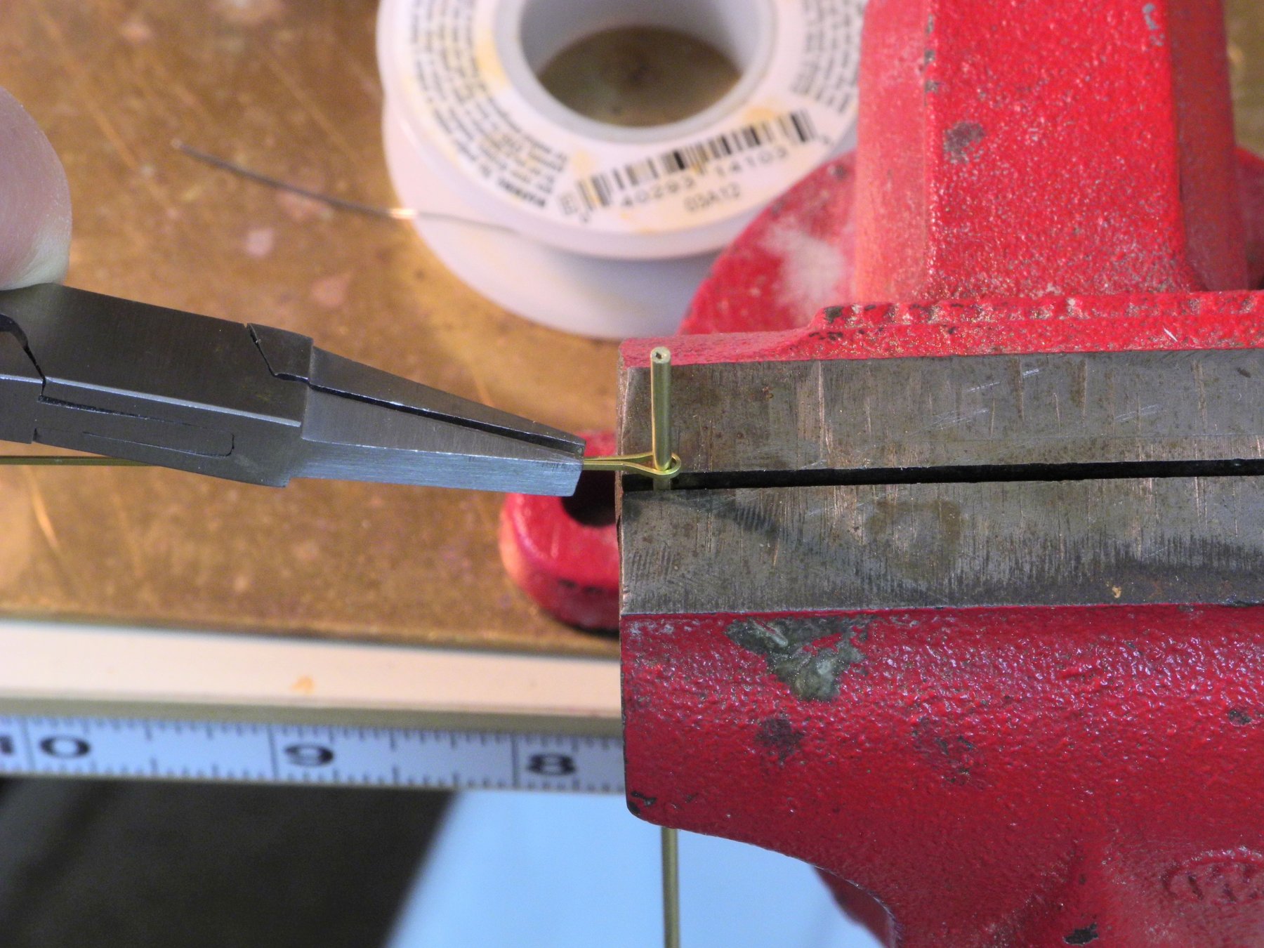
For the large loops, I used 1/32” x 1/64” brass strips. They were annealed and bent around a piece of 1/16” rod that would provide a consistently sized opening. I was careful not to close the bend into too tight of a shape.

The workpiece was then clamped for soldering.


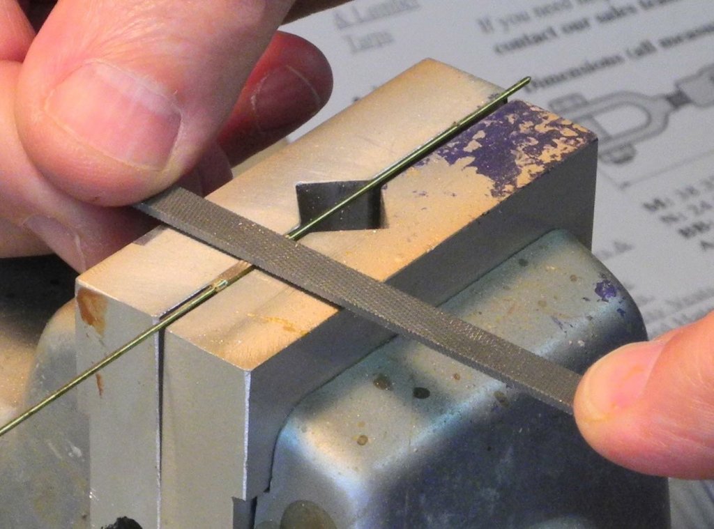
The shaft of the loop was then made into a 1/32” round shape by grinding and filing, so that the collar mentioned above would fit over the shaft.
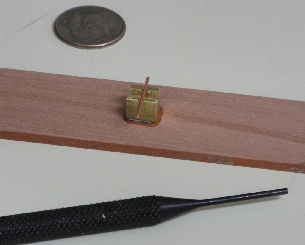
The shackles were made from 26 gauge copper wire. A jig was used to ensure that the bend of each shackle was as identical as possible.
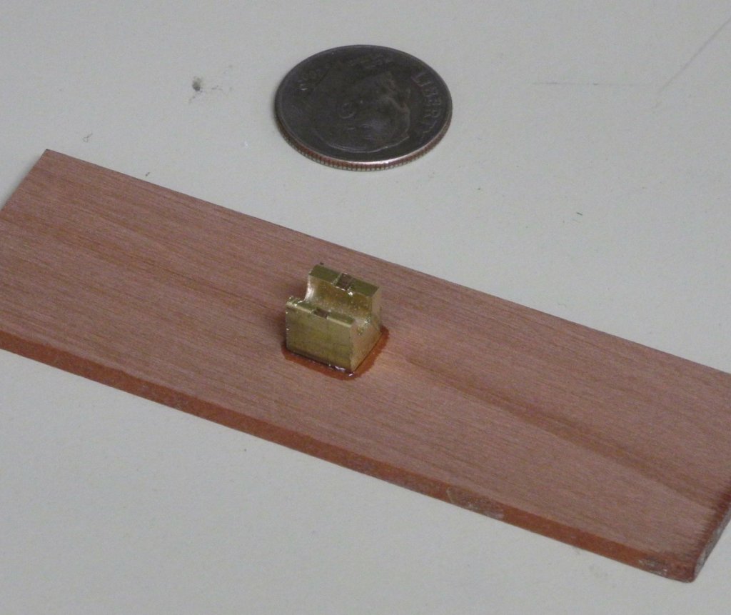
The copper wire was laid across the jig in the small groove that was cut perpendicular to the round cavity, and a 1/16” steel punch was used to push the wire down into the jig for the circular body of the shackle.

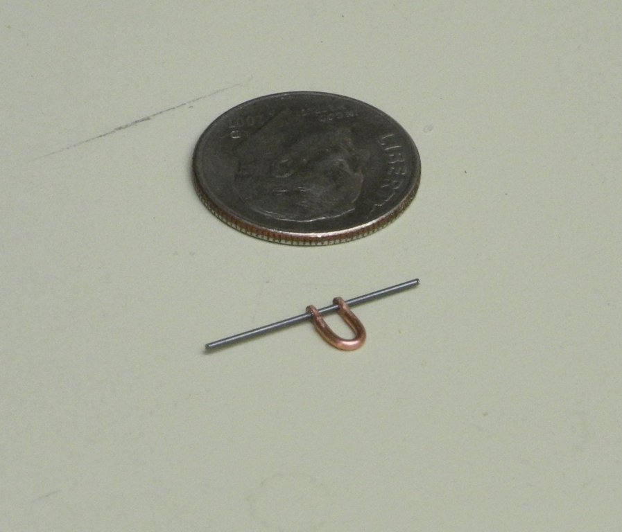
The ends of the shackle were cut to length, and then flattened by squeezing each end in the hinge of a flat pliers. Holes were drilled into the shackles for .019” pins, and the ends of the shackles were rounded by filing.
The turnbuckle and shackles were primed and then painted the bare metal color.
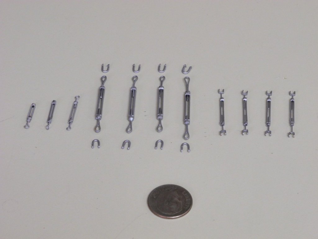
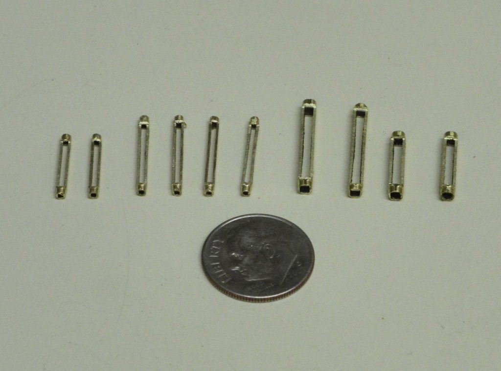
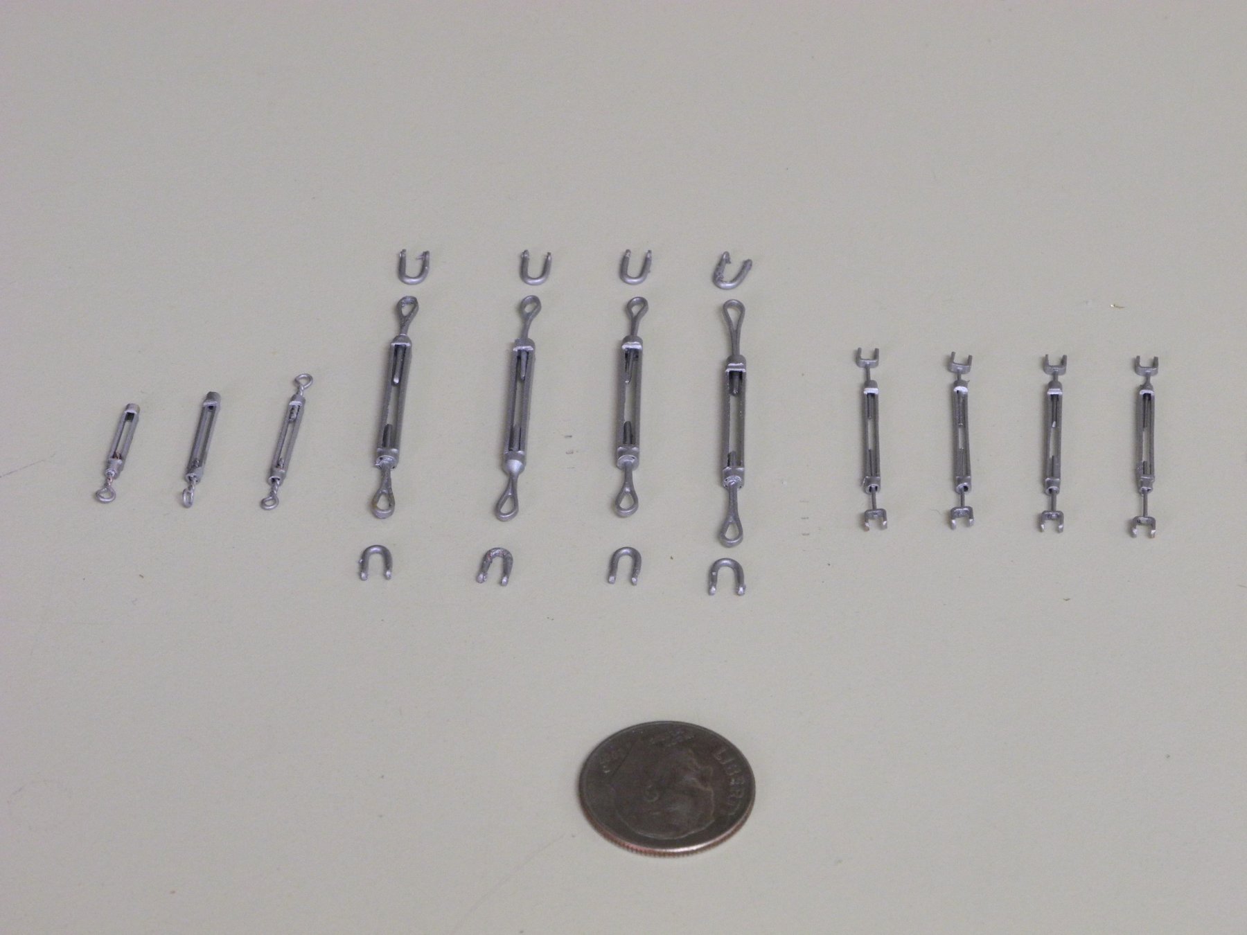
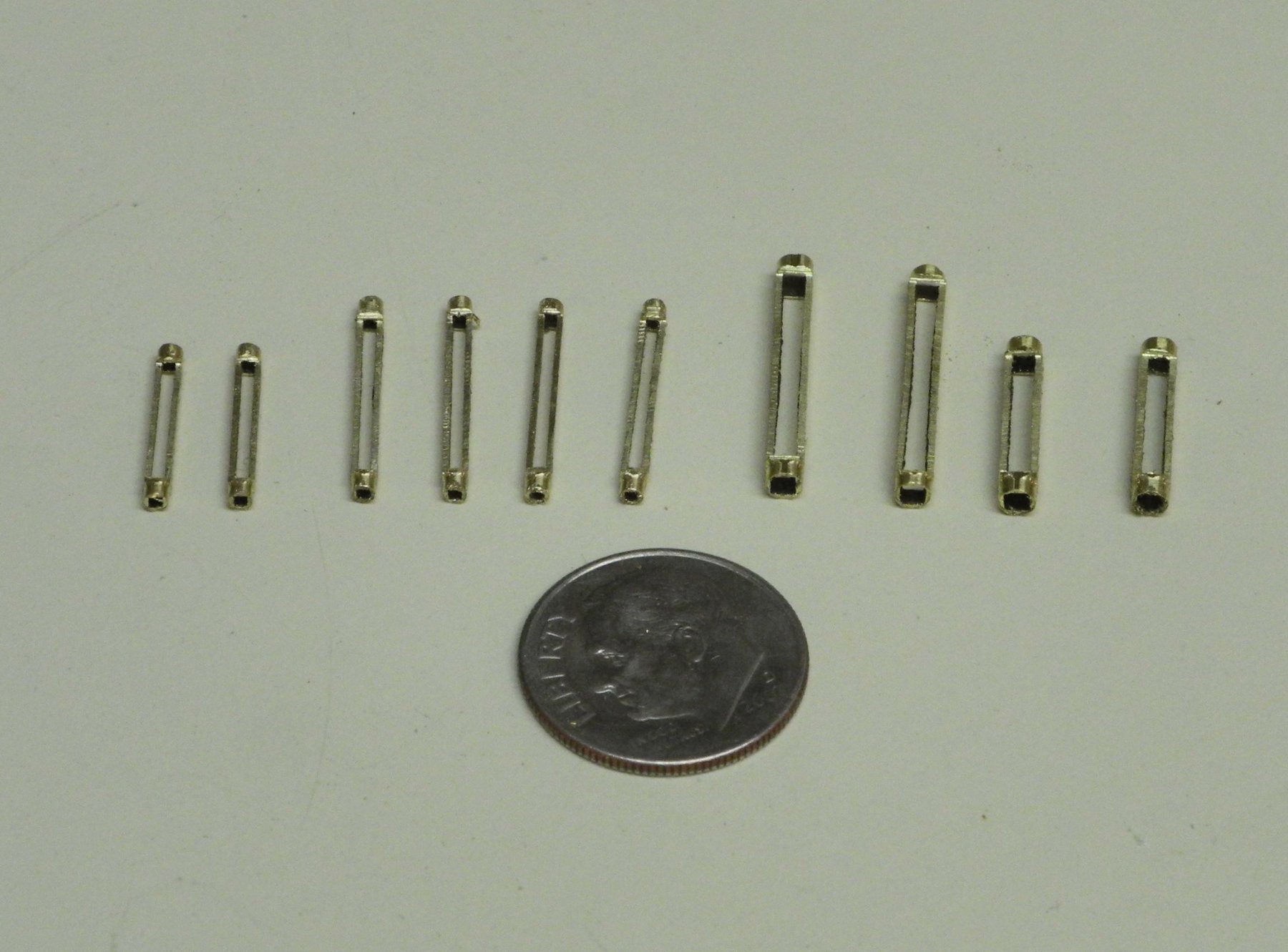
In all, Kathryn has 11 turnbuckles in her rigging, shown in the following photo.
I have ordered some bare stainless steel fishing line in the appropriate sizes for Kathryn’s cables. In the meantime, I plan to install some of the chains. The chains and turnbuckles for the Jack Stays will be installed first. That will be the subject of the next post.
Thanks everyone!
-
-
Part 74 –Turnbuckles - revisited
In Part 44, back in December, I had posted some work on trying to make turnbuckles. At the time I was trying to thread one end so that there would be working turnbuckles on the model. I was able to get a working turnbuckle from wood, but I wasn’t happy with the result.
Now that we’re getting very close to rigging the model, it’s time to get serious about putting some turnbuckles together.
Kathryn has 7 turnbuckles at the bow, supporting things like the Jib Stay, Head Stay, Bob Stay, and 4 Jack Stays. The following photo shows most of these turnbuckles.

All of these turnbuckles seem to be of a uniform width. The turnbuckles for the Jack Stays appear to be longer than the others.
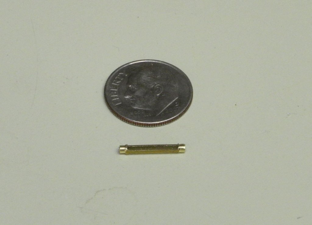
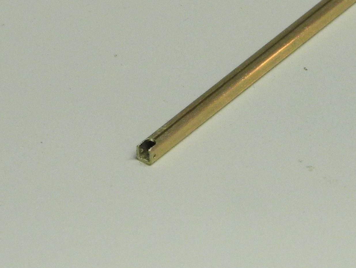
Square brass tube was used to make the turnbuckle bodies. 1/16” square tube was used for the turnbuckles at the bow, and 3/32” square tube was used to make the four larger turnbuckles that support the shrouds.
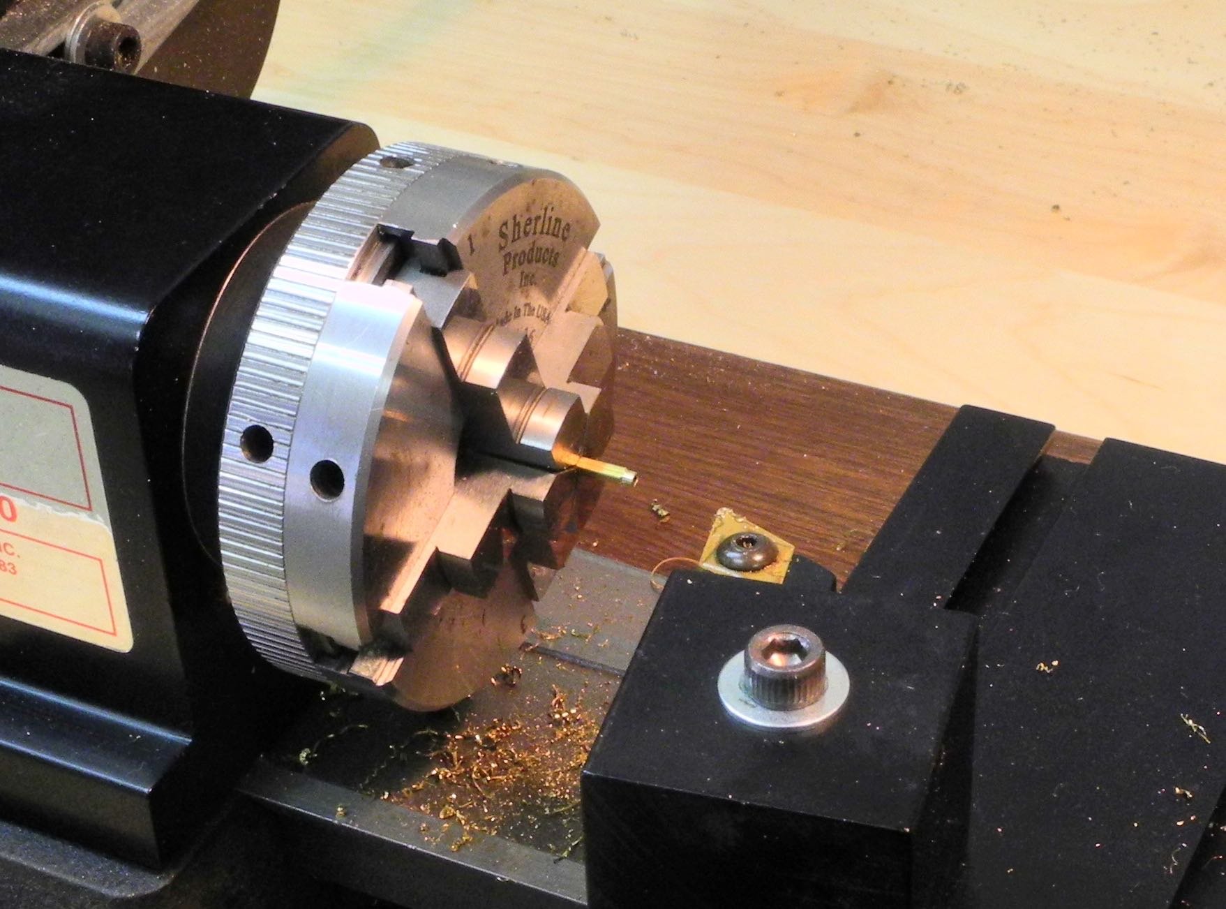
The first step, after cutting an appropriate length of tube using the micro saw, was to round both ends of the piece on the lathe – removing about .015 of material.

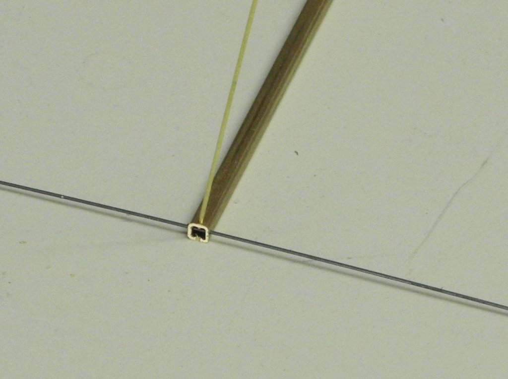
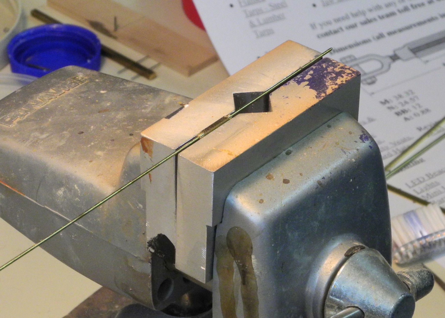
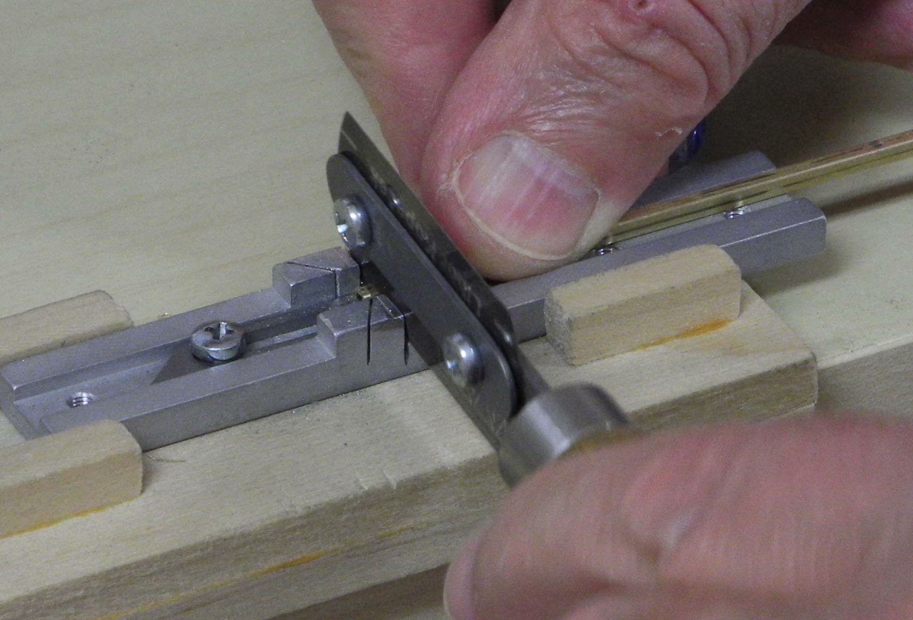
The workpiece was then held in a vise. A piece of thin rod was run through the workpiece as an aid in holding and positioning it in the vise.

Two of the sides (facing each other) were removed by filing.
Most of the turnbuckle bodies were made during one session.
The 2 turnbuckles for the Jack Stays shown in the first photo have different connectivity components. One seems to have clevises at both ends, while the other has rings with shackles attached. I decided to make them all the same way, using clevises for the connecting ends.
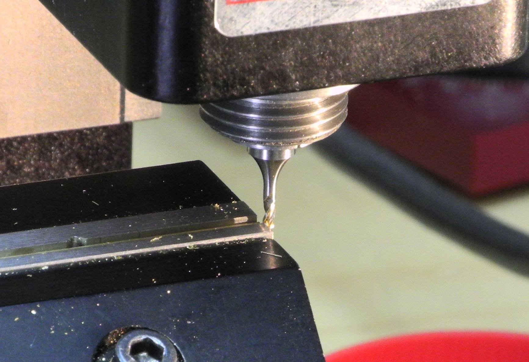
The 3/32” square tube was used for making the clevises. A hole was drilled through the top side of the tube to take the connecting rod. The tube was then repositioned in the vise so that a hole could be drilled through both sides of the tube for the clevis pin.
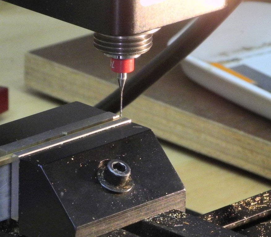
The tube was then turned in the vise so that the last undrilled side was exposed, and this side was milled off using a 1/16” end mill.


The clevis was then parted off using the micro saw.

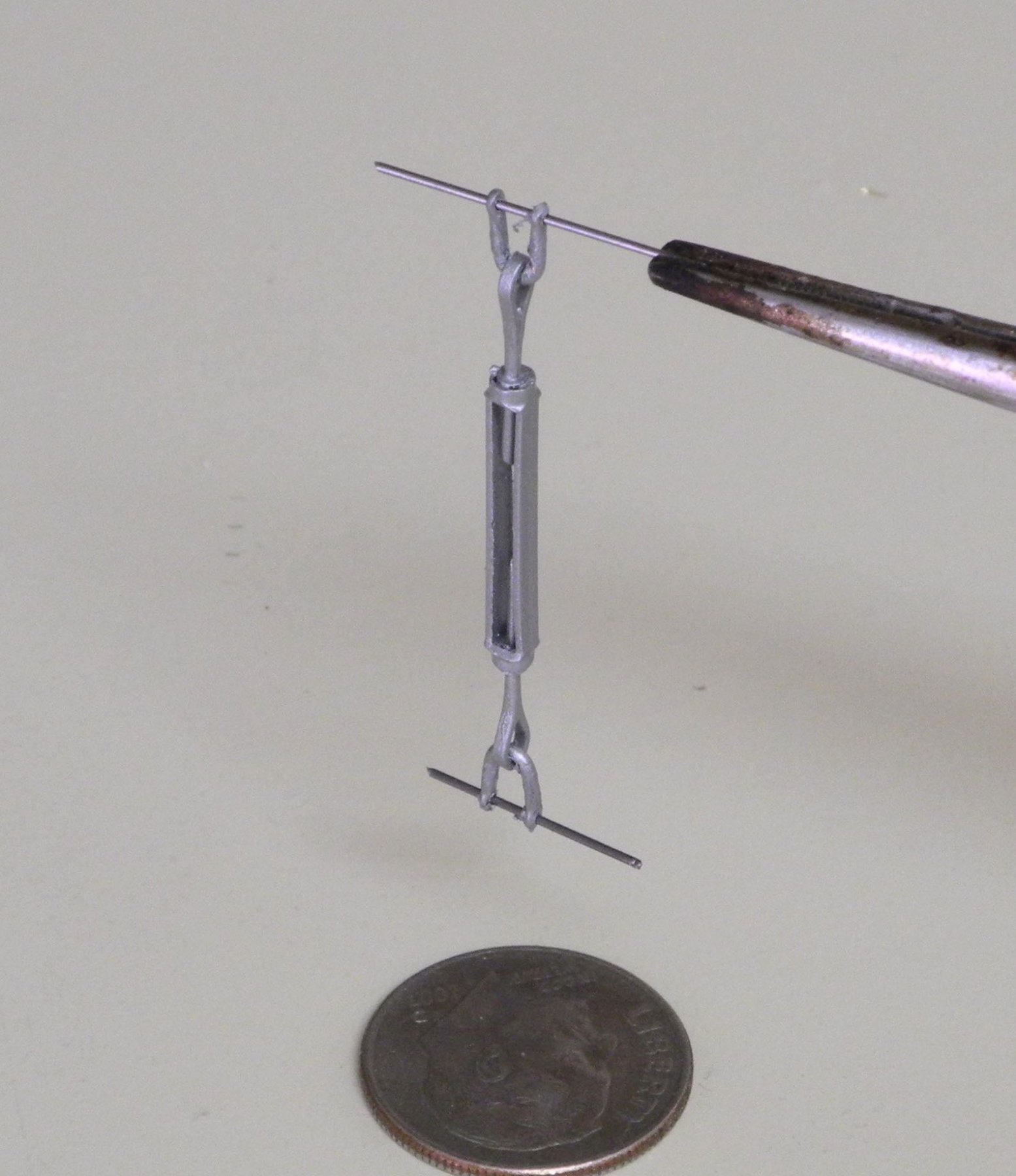
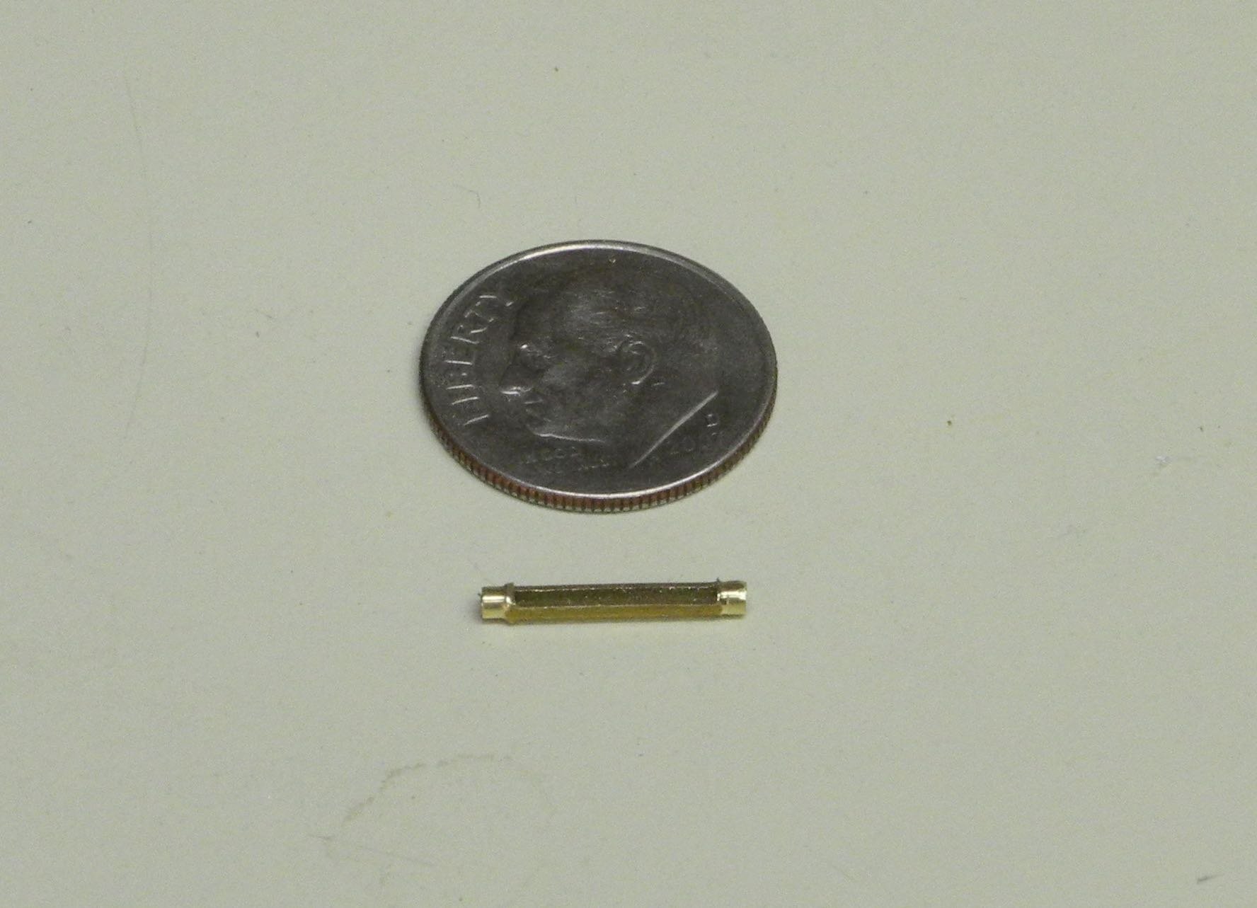
The clevis was soldered to a connecting rod, and the rod was soldered into the turnbuckle body. After the clevis and rod for the other end of the turnbuckle was assembled and installed, the turnbuckle was primed and painted the bare metal color previously used for the yawl boat davits.

A total of four of these turnbuckles will be required. The one shown was actually a first prototype and will be used along with the other three that still need to be assembled.
The other turnbuckles at the bow will be similar in size, but the connections will be somewhat different.
The most difficult turnbuckles to be made are the four large turnbuckles that support the shrouds. This will be subject of the next post – coming soon.
Cheers everyone.
- JerryTodd, paulsutcliffe, Canute and 16 others
-
19
-
-
Good start Maury - I'm signing up to follow along. Your C. Chase build is very similar to what I'll be doing on the J T Leonard after my current build of the skipjack Kathryn is finished.
- mtaylor, BETAQDAVE and thibaultron
-
3


Kathryn by Mahuna - FINISHED - 1:32 - Skipjack Based on HAER Drawings
in - Build logs for subjects built 1901 - Present Day
Posted
Thanks, John. This build has been a good learning experience for me, and I'm glad if others are benefitting from it as well.
Thanks Druxey. Since I have lots of photos of the real thing I decided to try to have the model as realistic as possible - including the mast wedges. I have to admit, though, that it took a while to work up the courage to step the mast. Now, after the fact, I don't think it was too difficult.
Thanks Ed - as I mentioned above, the many photos have been a real help.
Thanks Kurt!