


Mahuna
-
Posts
1,500 -
Joined
-
Last visited
Content Type
Profiles
Forums
Gallery
Events
Posts posted by Mahuna
-
-
23 hours ago, PETERPETER said:
Very pleased to see that you have passed through the most difficult part of your recent event and good to see you back to work on Kathryn.
I note that you have not pencil lined the sail to represent seamed cloth panels. Possibly the sail was not made up from seamed panels??? You have also shortened the height of the sail, (with fewer hoops) so that the furled and tied appearance will be visually to scale. Your wire shrouds and stays, using Surfstrand fishing leaders add realistic detail to your Kathryn. All around superb work.
Hi Peter. Thanks for checking in. Kathryn's sails, like all others, are in fact made from panels, but I decided not to show the seams because I'd be furling the sails and didn't think the seams would be necessary on the model.
-
20 minutes ago, thibaultron said:
Glad to see you back Frank!
Thanks Ron - and it's good to hear from you.
- Omega1234, thibaultron, mtaylor and 1 other
-
 4
4
-
8 hours ago, Omega1234 said:
Hi Frank
It’s great that you’re back on deck and able to get some work done on Kathryn.
Superb work, as always.
All the best.
Cheers
Patrick
Hi Patrick - great to hear from you. Yeah, it's really good that life has got back to being somewhat 'normal'.
-
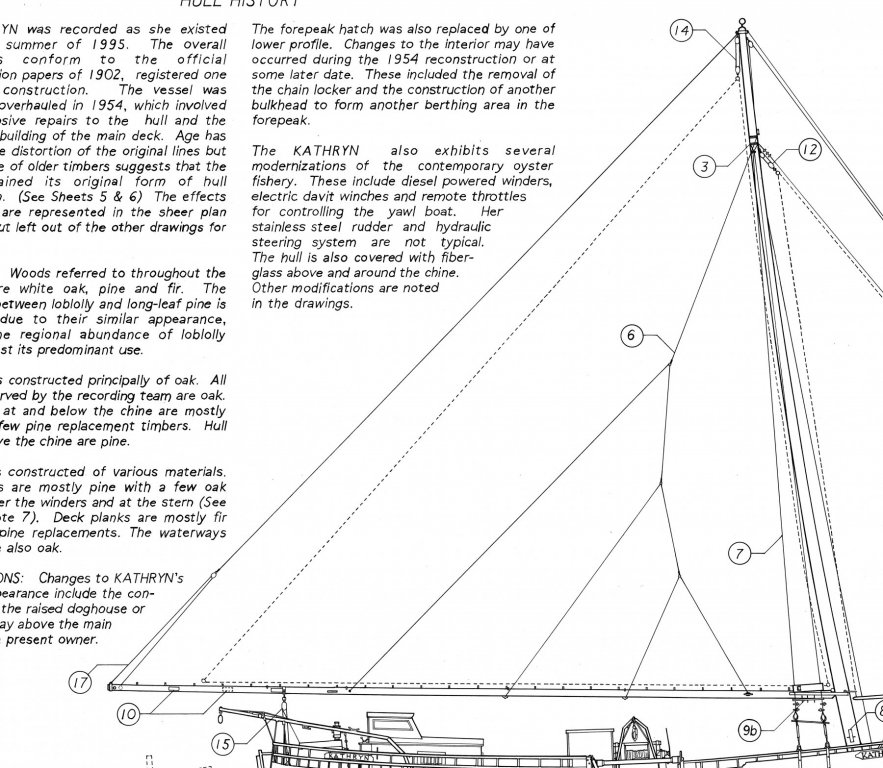
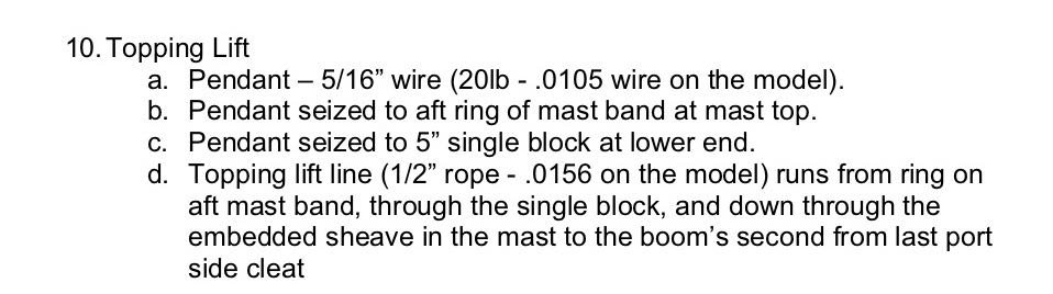
Part 84 –Topping Lift
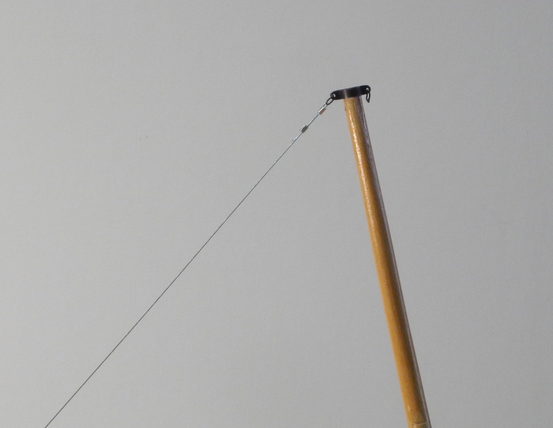
Kathryn’s Topping Lift consists of a wire pendant hanging off the masthead band via a shackle with a single block at the lower end of the pendant, and the tackle running from the ringbolt at the aft boom band, through the pendant’s single block, and back down through the sheave embedded in the boom just forward of the aft boom band.
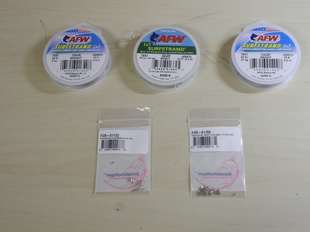
I was able to find some uncoated stainless steel fishing leader in various sizes that will make acceptable wire stays and shrouds. I also found crimping beads from Beadaholique that will serve as the fasteners for the wire components.
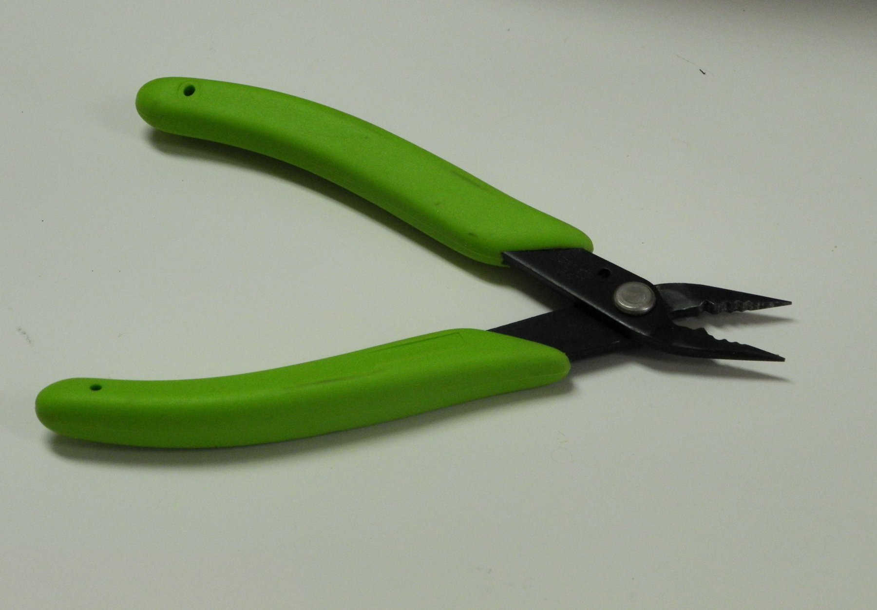
Crimping pliers from Xuron are the tool used for crimping the fasteners.

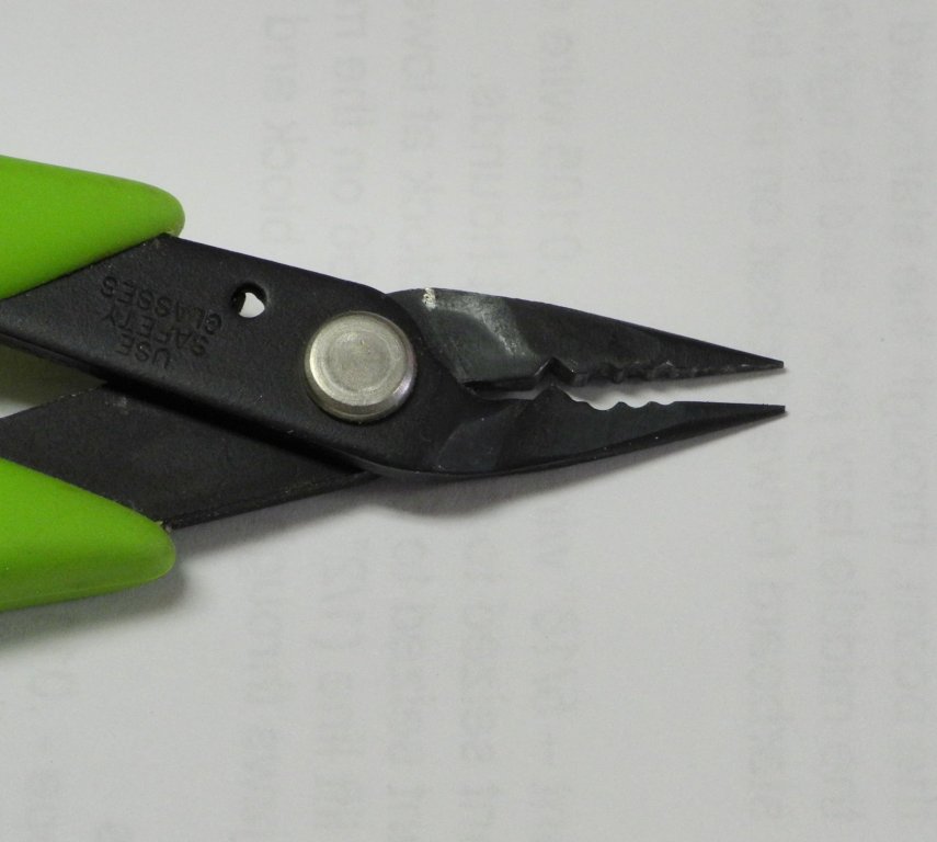
The rearmost jaws perform the actual crimping, and the forward jaws help to shape the crimped beads.
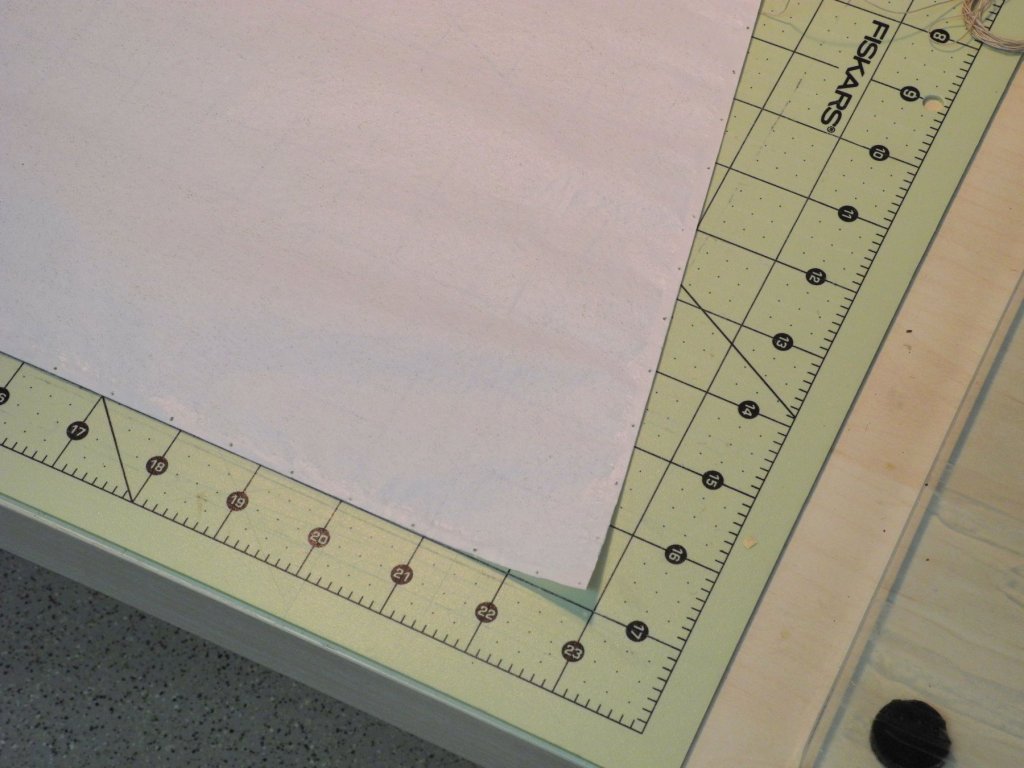
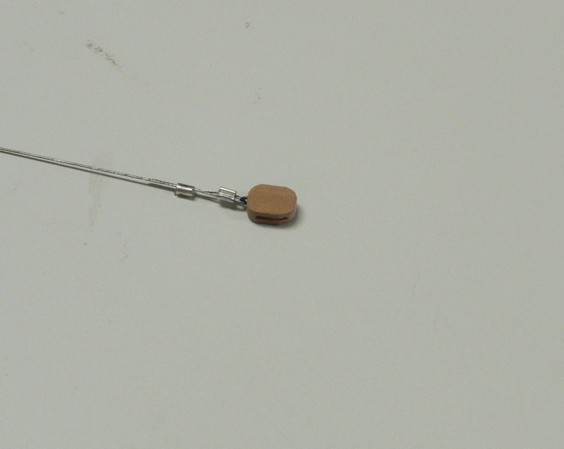
I used two crimping beads at each end of the Topping Lift Pendant.
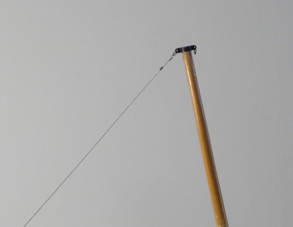
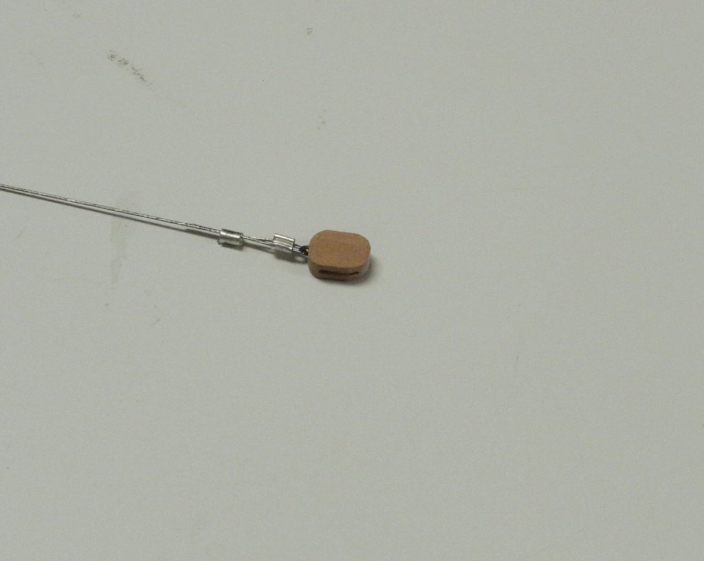
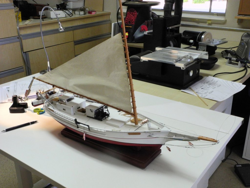
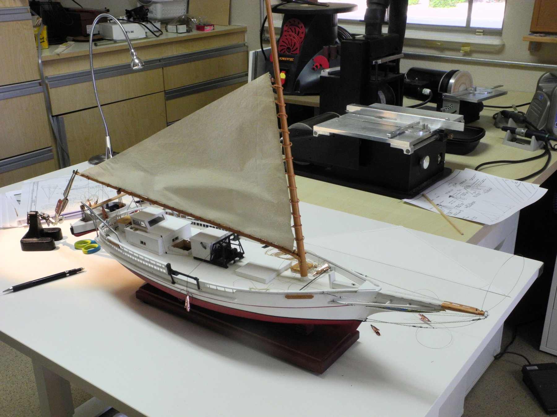
The following photo shows the completed and installed Topping Lift.
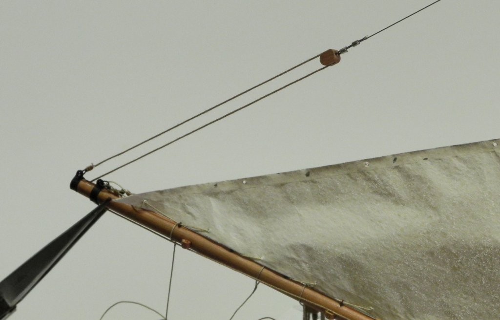
This completes the posting for the work that was done prior to my long absence. Furling the Mainsail will be the topic for the next post.
-
37 minutes ago, druxey said:
Looking very nice indeed. I like the subliminal advertising for Jim Byrnes in the background!
Thanks, Druxey - I don't mind showing off Jim's tools, wouldn't be without them!
21 minutes ago, Roger Pellett said:Welcome back Frank!
Roger
Thanks Roger. It is good to be back.
- thibaultron, Canute, mtaylor and 1 other
-
4
-
1 hour ago, GuntherMT said:
Very good to see you back Frank, and I'm extremely happy that things are turning out well for you. Hope to see her in person one of these days!
Thanks Brian. You're welcome any time.
- Omega1234, thibaultron, mtaylor and 1 other
-
4
-
Part 83 –Mainsail cont’d
Hi Everyone
Thanks again for all of the good wishes during a very difficult time. Things have improved significantly and we’re back to fairly normal circumstances, so I’ve been able to put a little time in the shop and back to work on Kathryn. The next couple of posts will catch us up on work that had already been completed, but had not yet been posted in the log.
We had left off with attaching the mast hoops to the mainsail. There was still a little more work required before bending the sail to the mast.
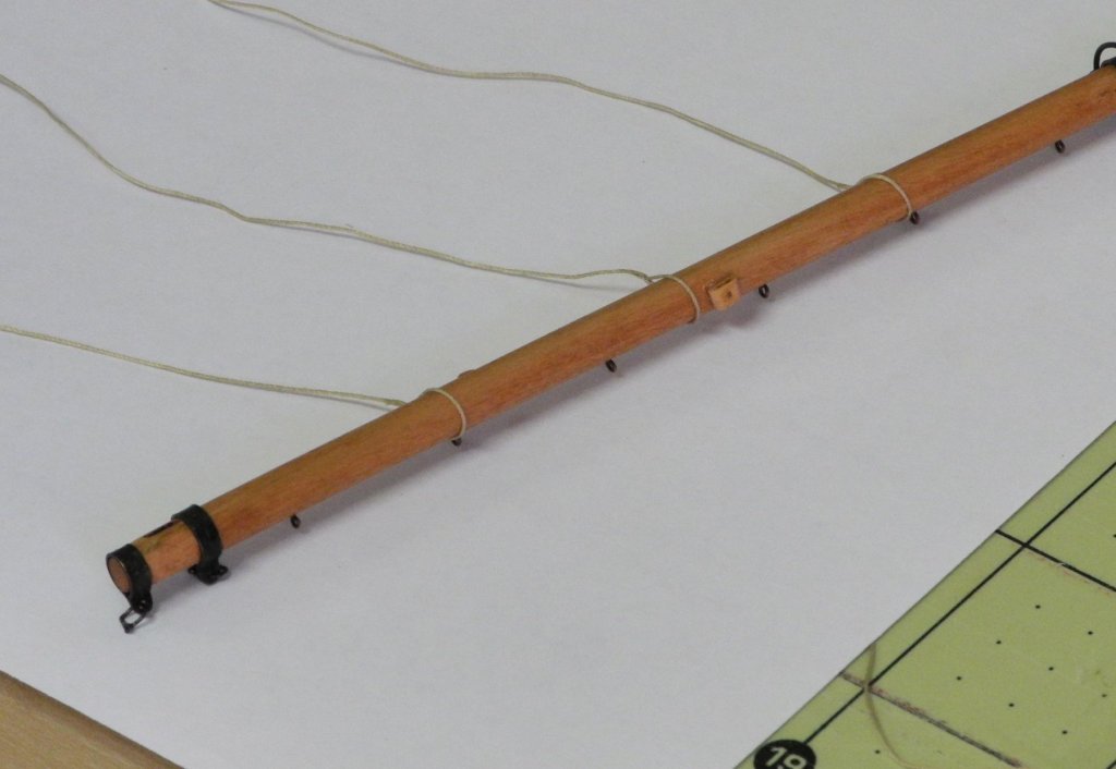
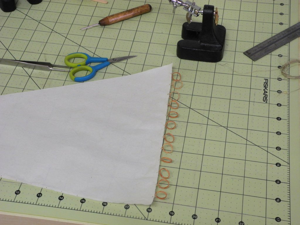
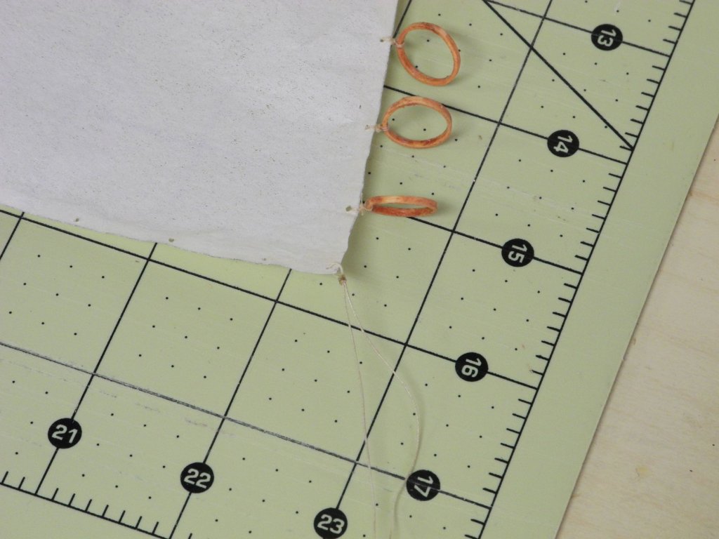
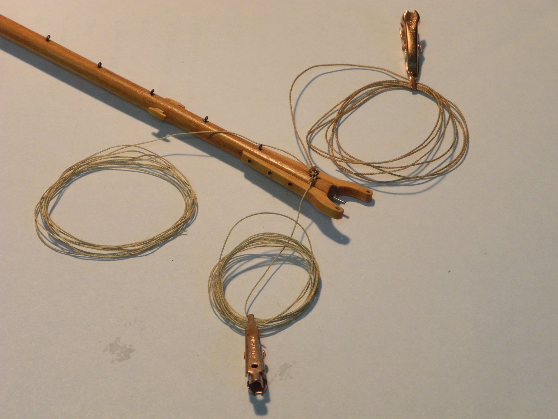
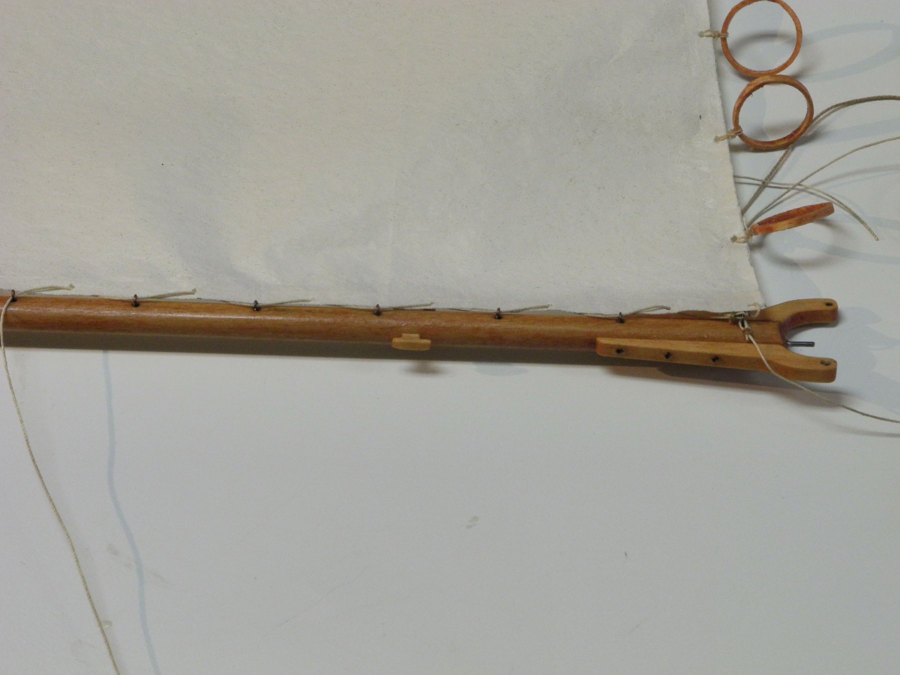
Three lines were seized to ringbolts at the boom jaws, as in the following photo.
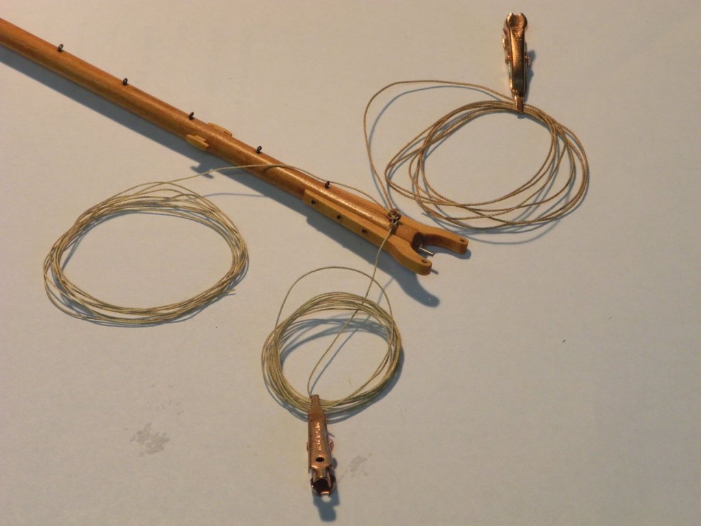
The line at the bottom of the photo is for wrapping the furled sail.
The middle line is for lacing the sail to the boom.
The top line is for the boom lift.
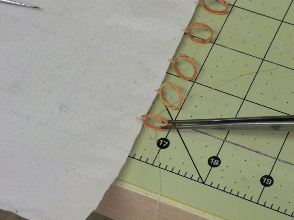
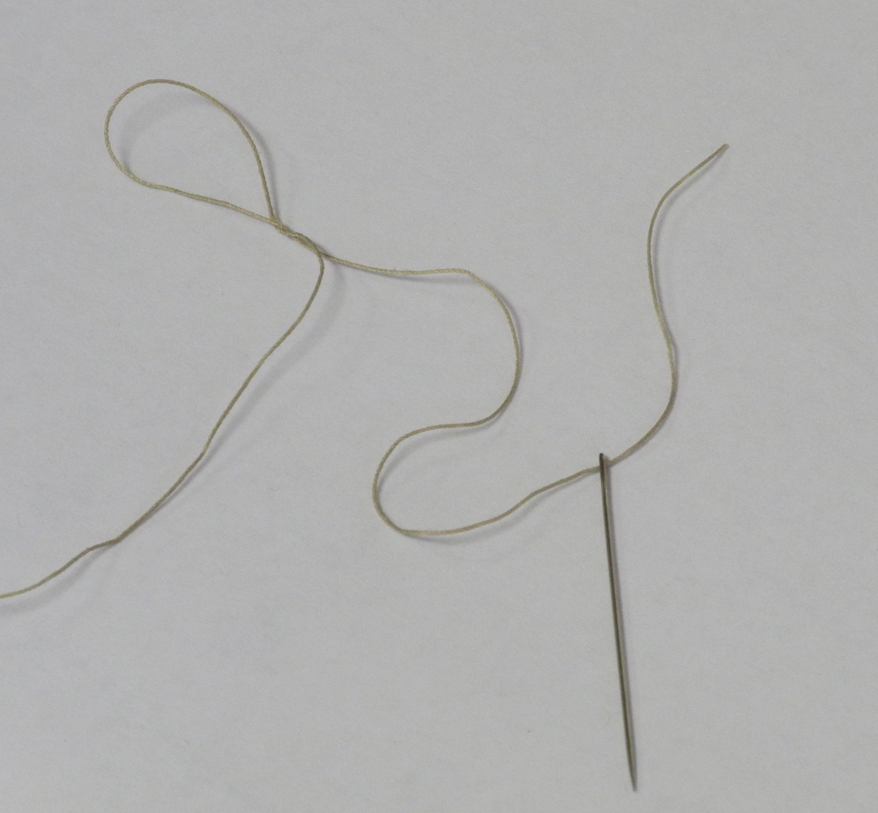
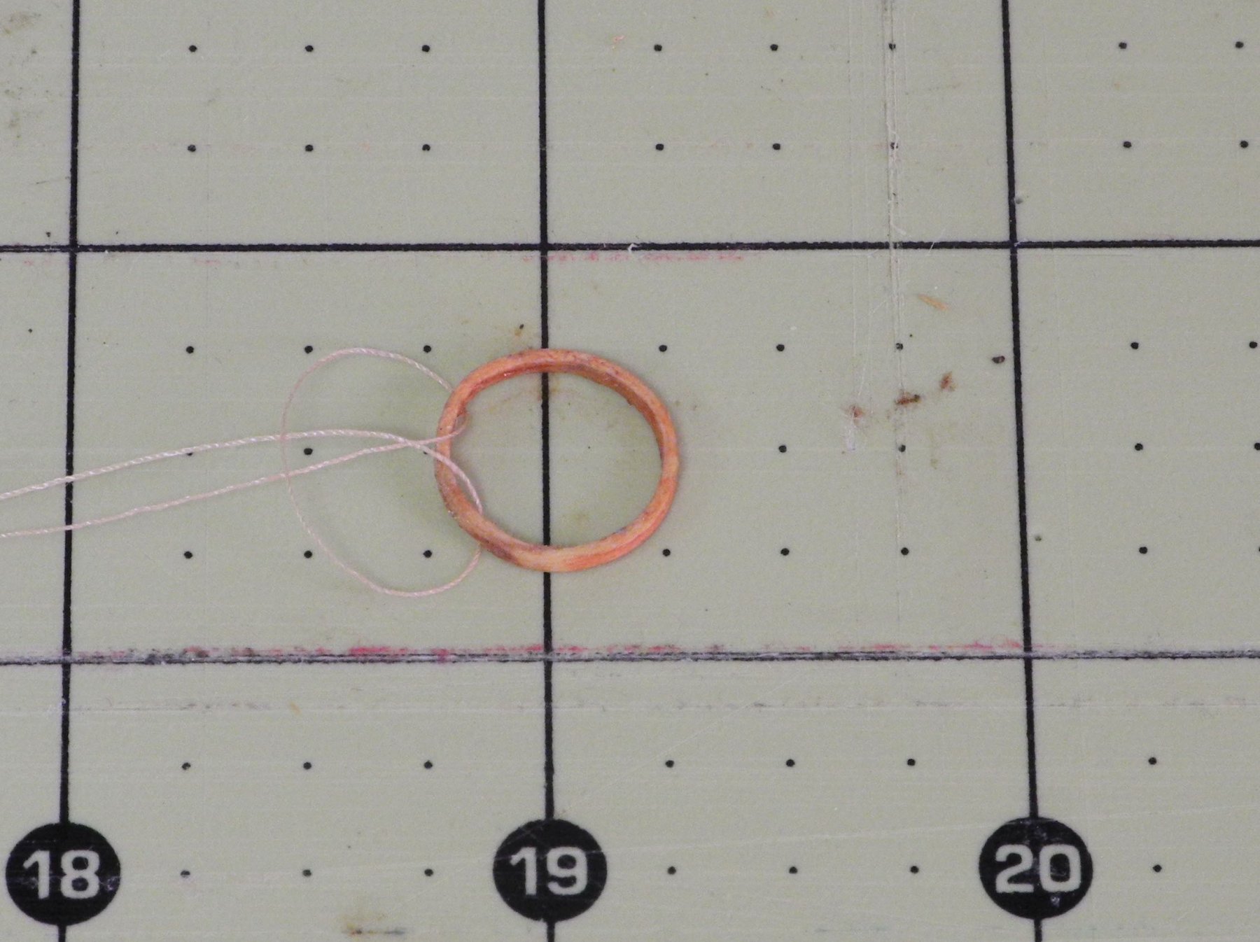
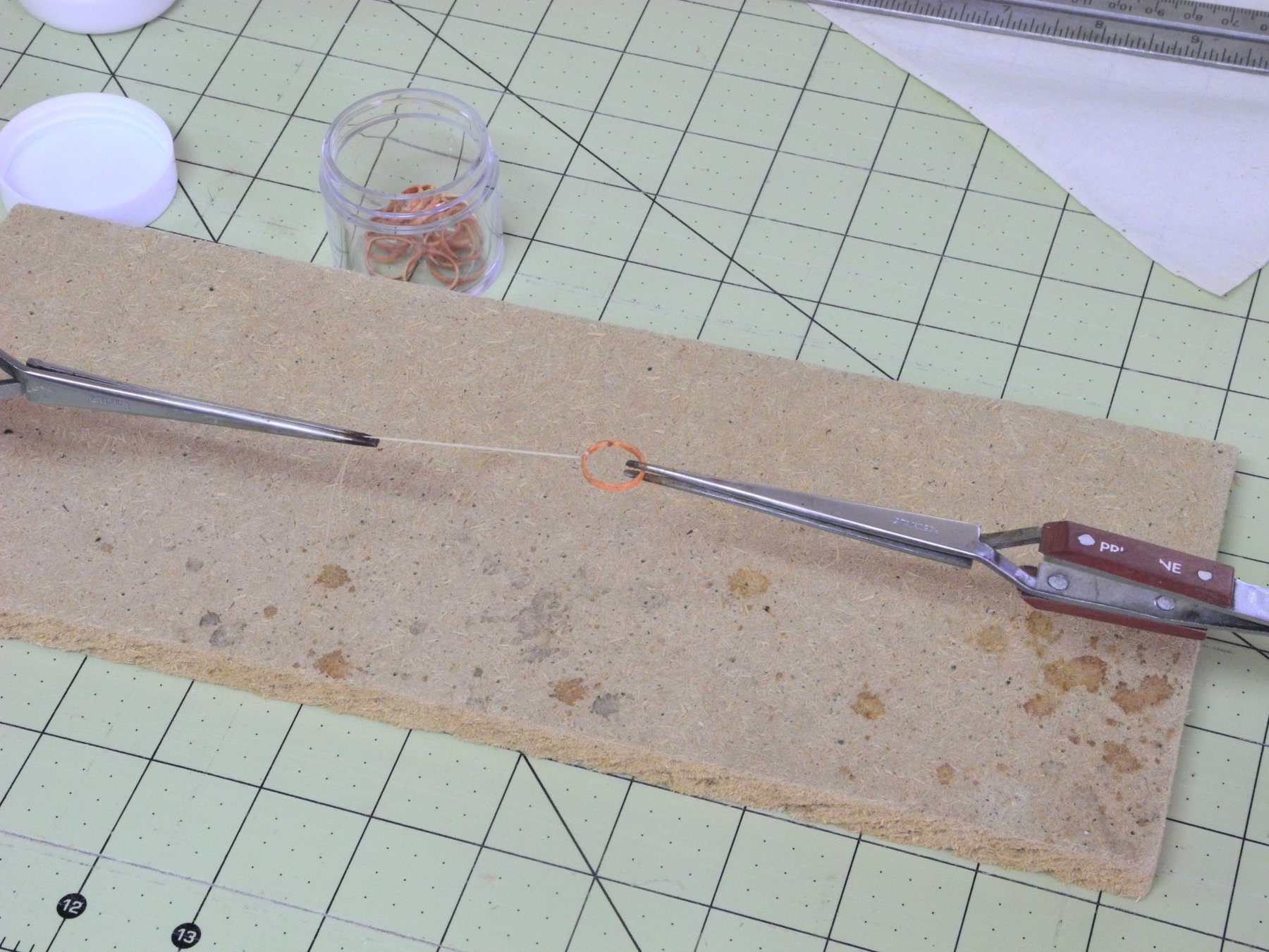
Before the sail can be laced to the boom, 3 reefing tackles need to be attached to the boom. These lines are spliced to form loops that encircle the boom, are then run up to the leech of the sail, down through the reefing (cheek) blocks on the boom and finally to cleats positioned on the boom. The loops formed by these splices need to be adjustable, so I formed them as follows:
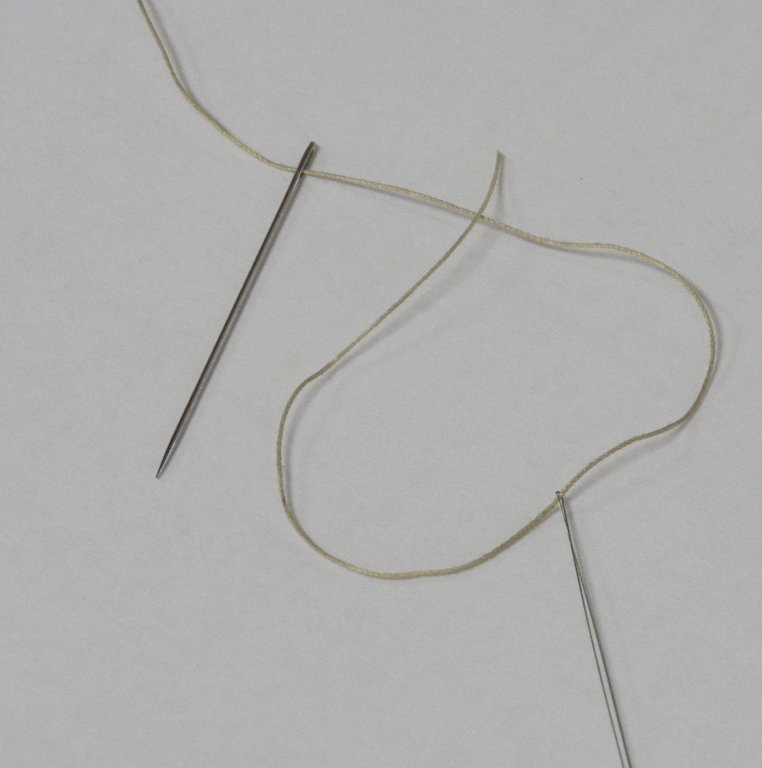
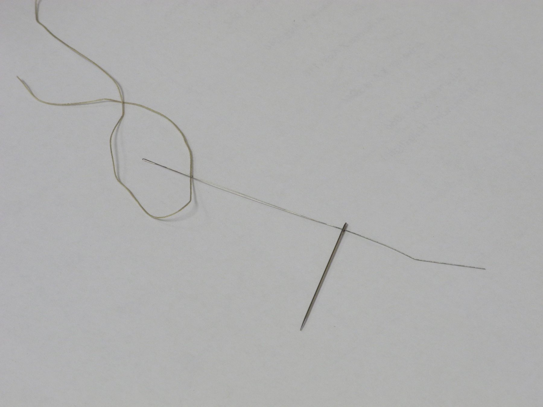
First the line for the reefing tackle was passed through a needle threader, which was then positioned through the eye of the needle.
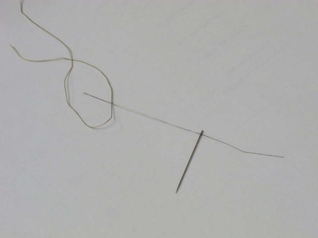
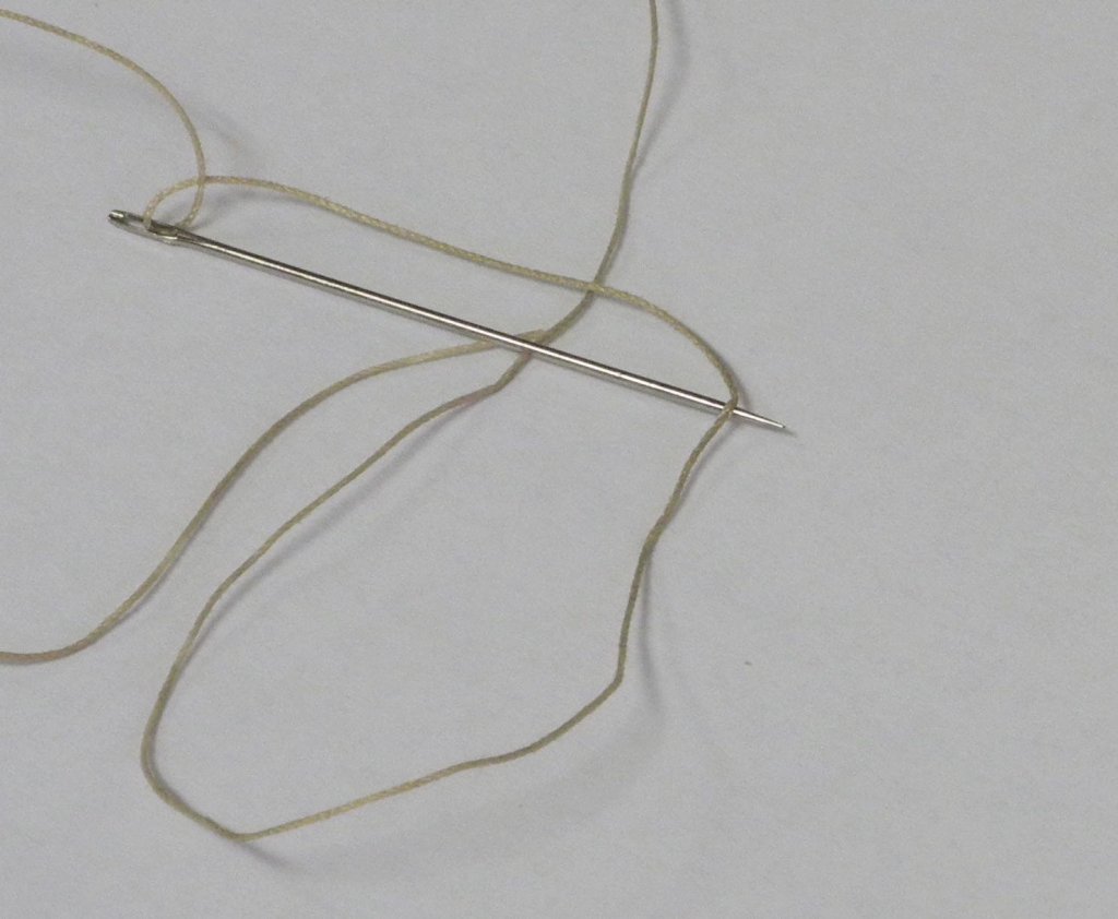
The line was then pulled through the eye of the needle.
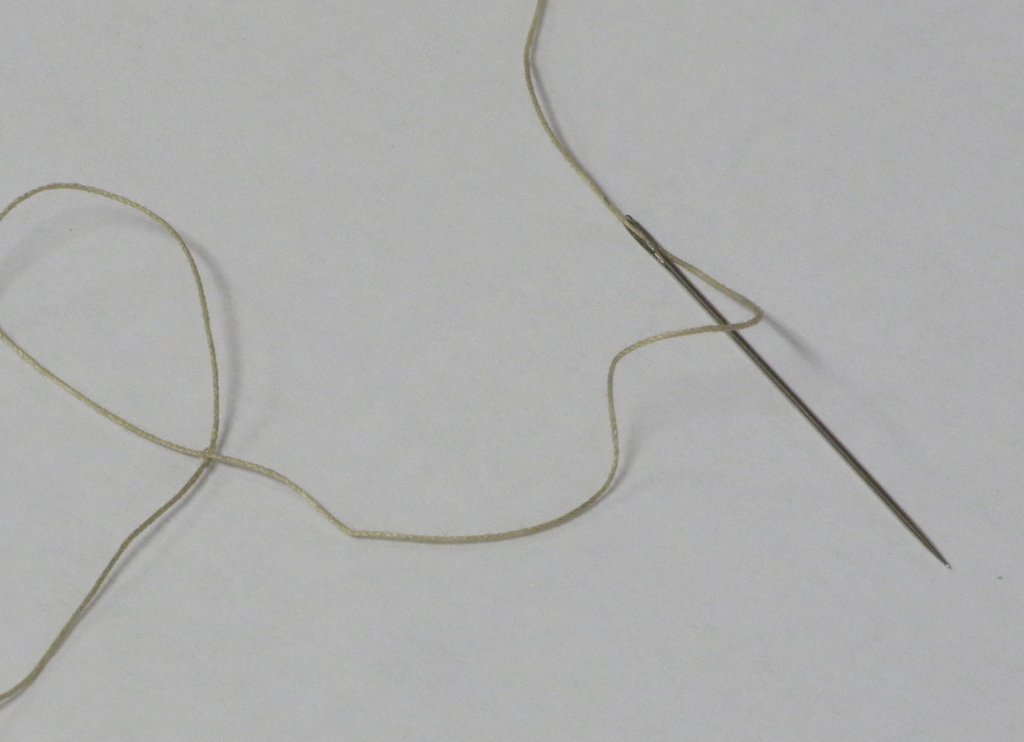
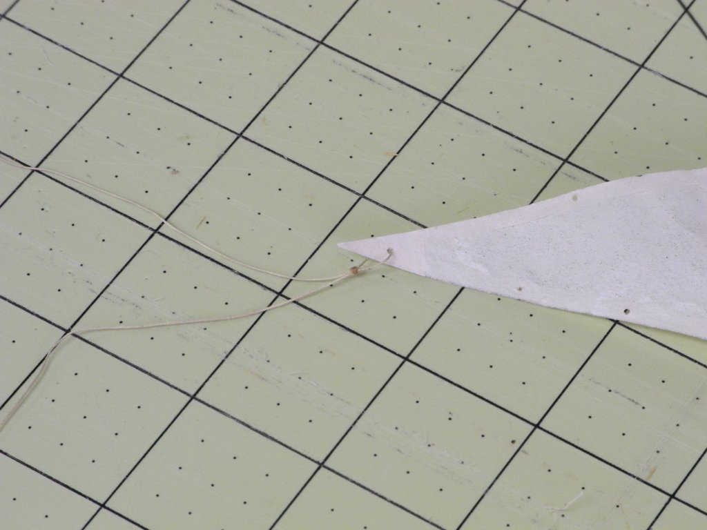
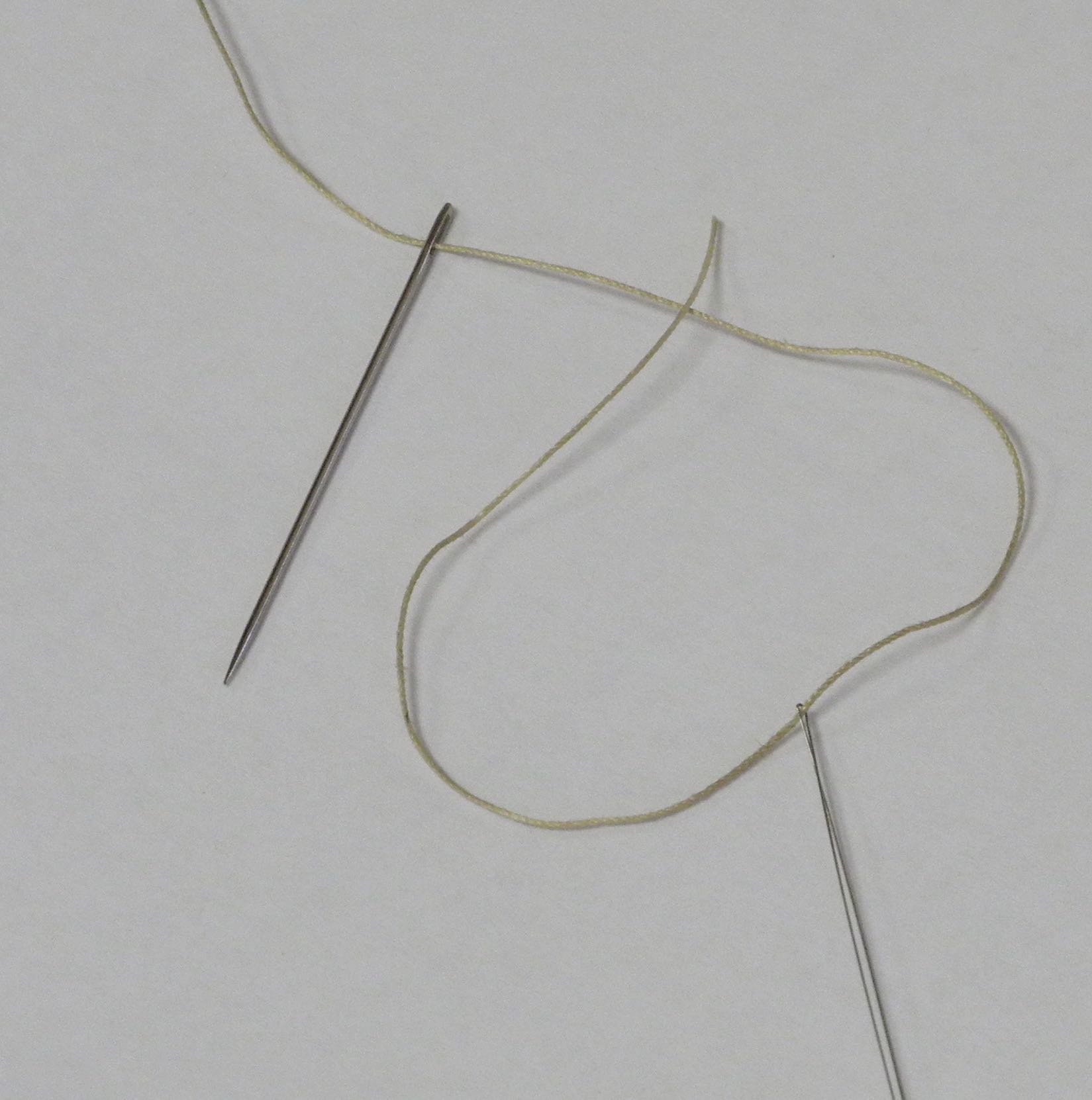
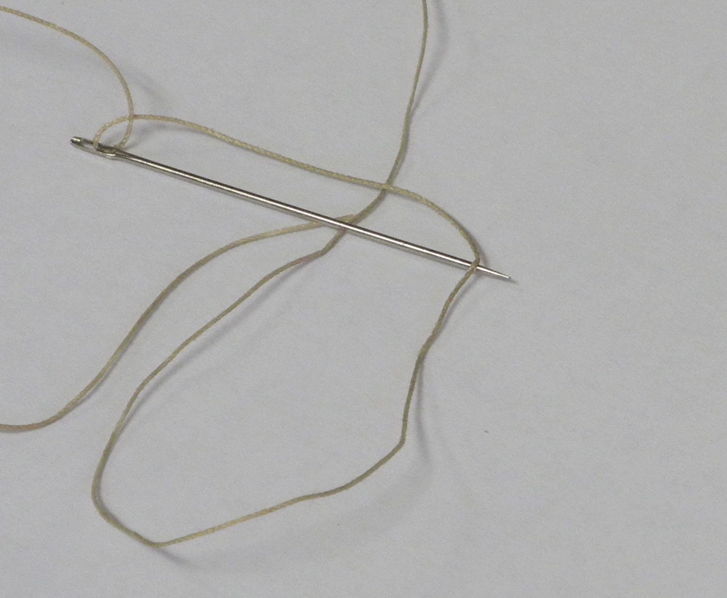
The needle was passed through the line
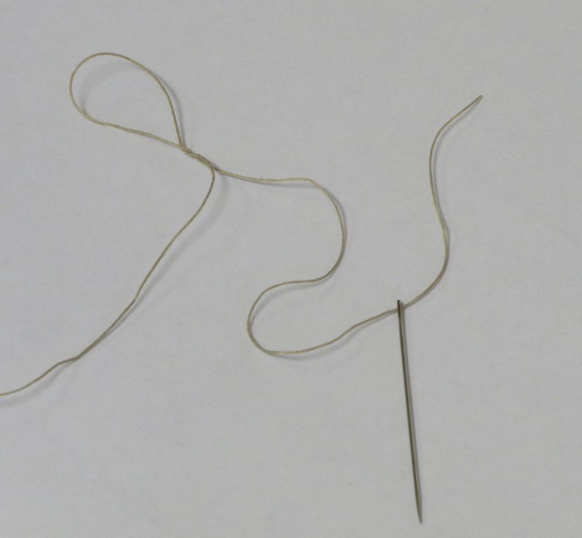
and the line was pulled through the opening made by the needle to form a loop and the first part of the splice.
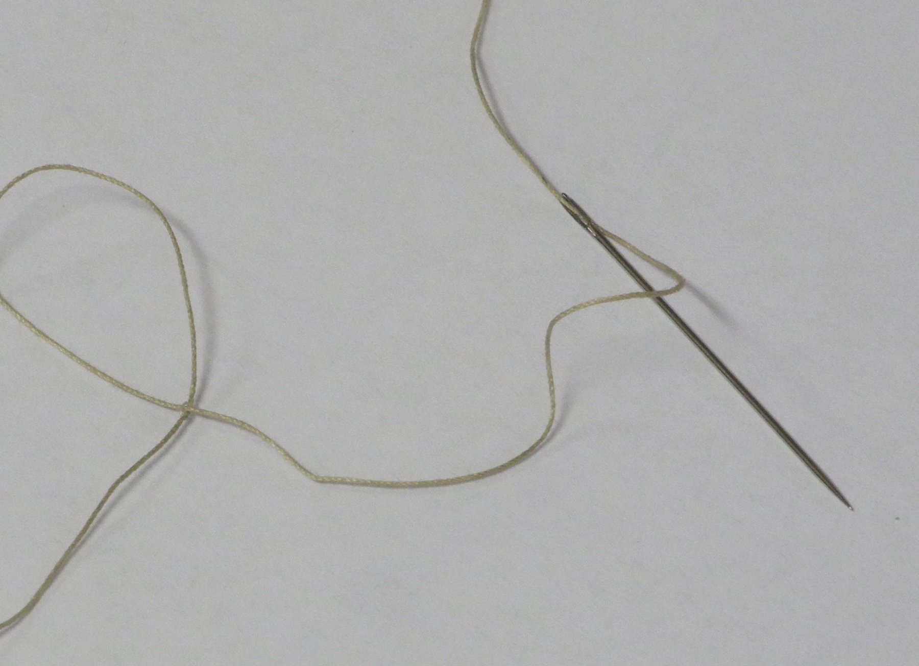
This process was repeated again to form the rest of the splice.
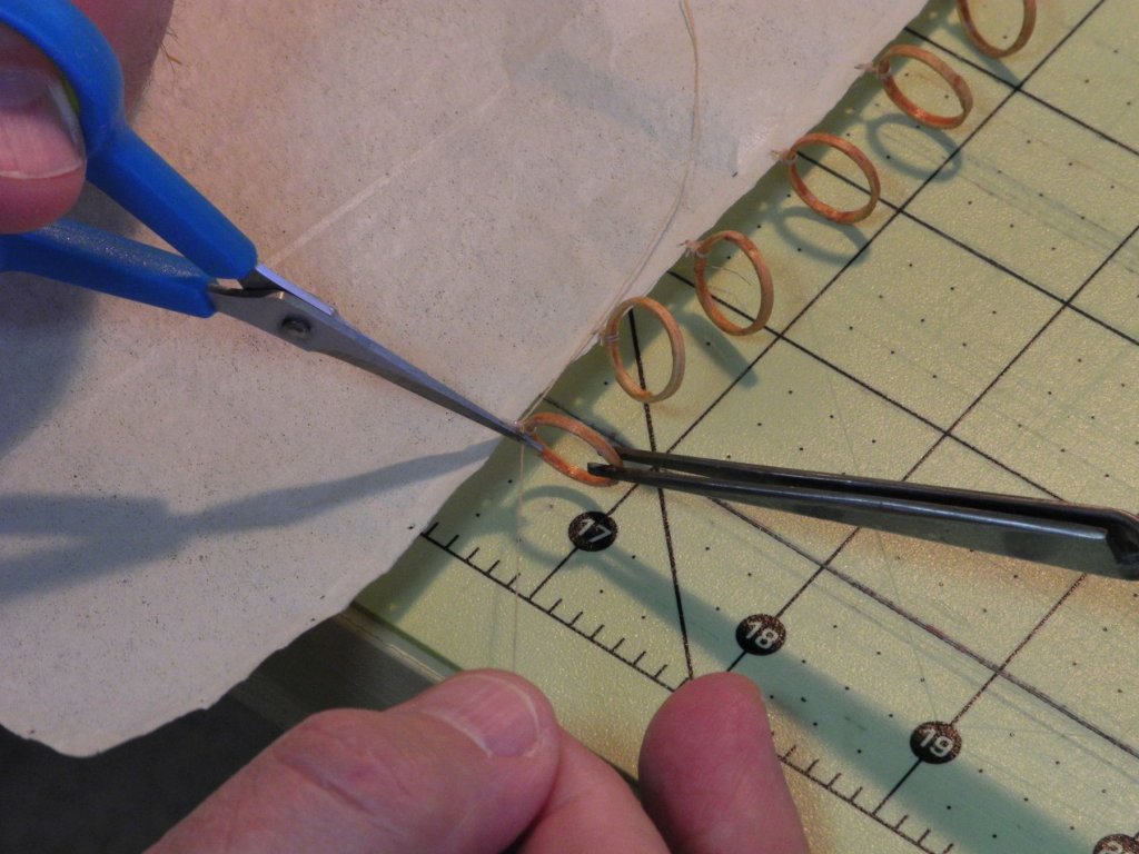
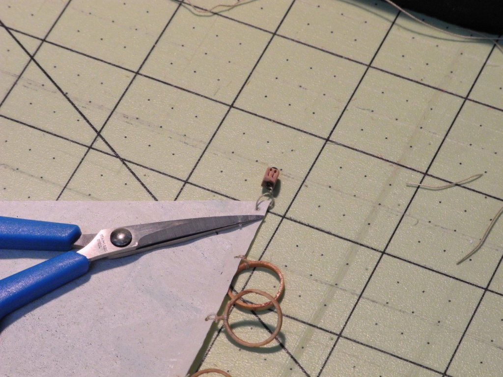
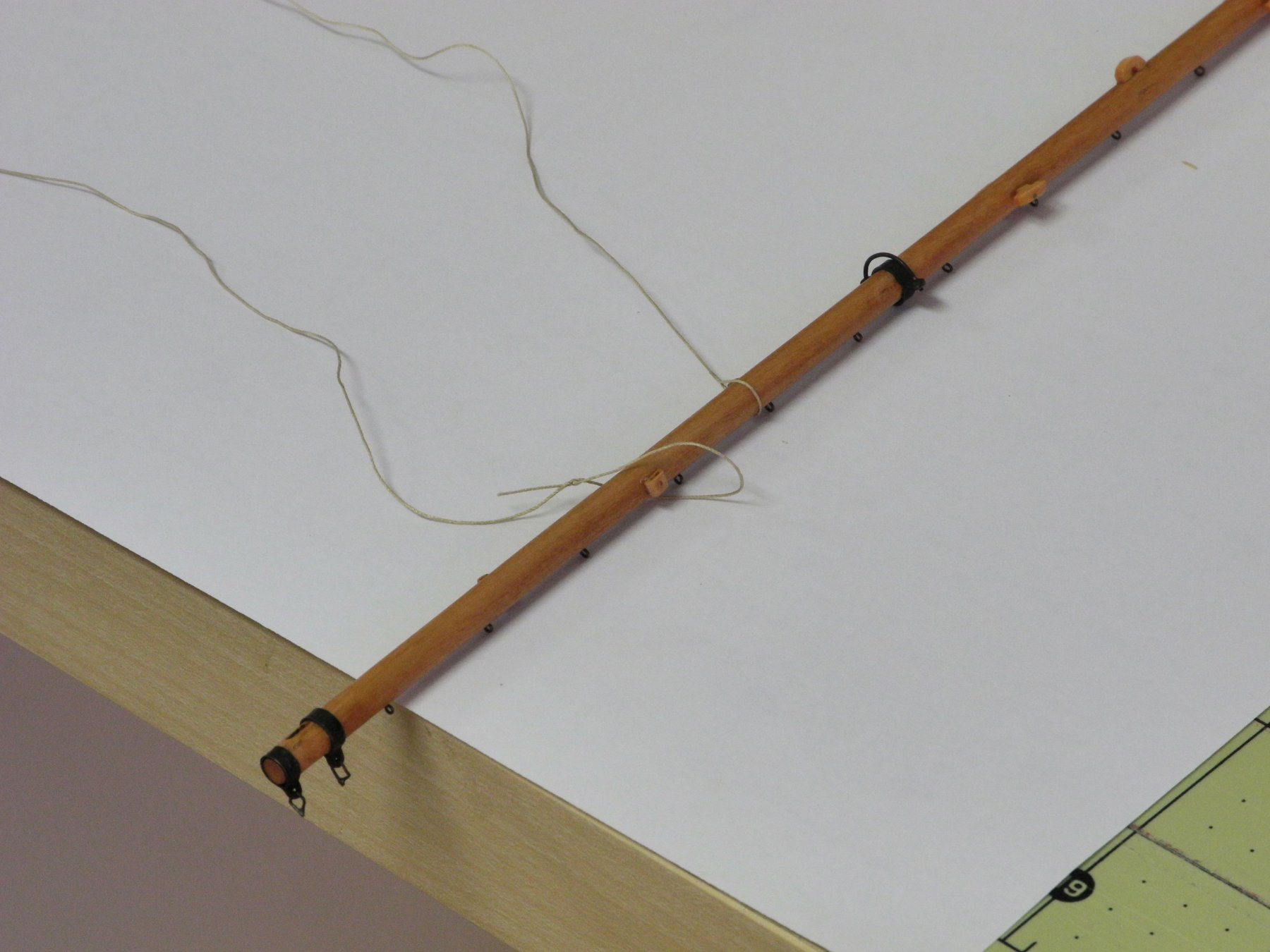
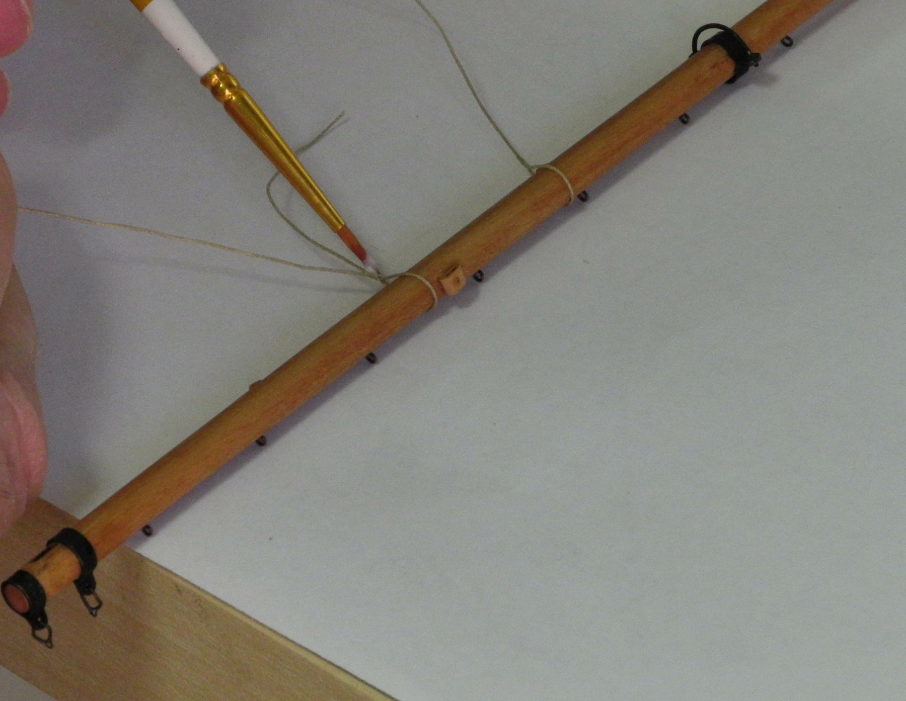
The loop was positioned on the boom and the reefing tackle was then pulled tight to form a loop that properly fit the diameter of the boom. The splice was hit with a spot of diluted white glue and rolled between thumb and finger to round it, and when dry the loose end of the line was trimmed. The following photo shows a reefing tackle that is being positioned on the boom, along with one that has been tightened and trimmed.


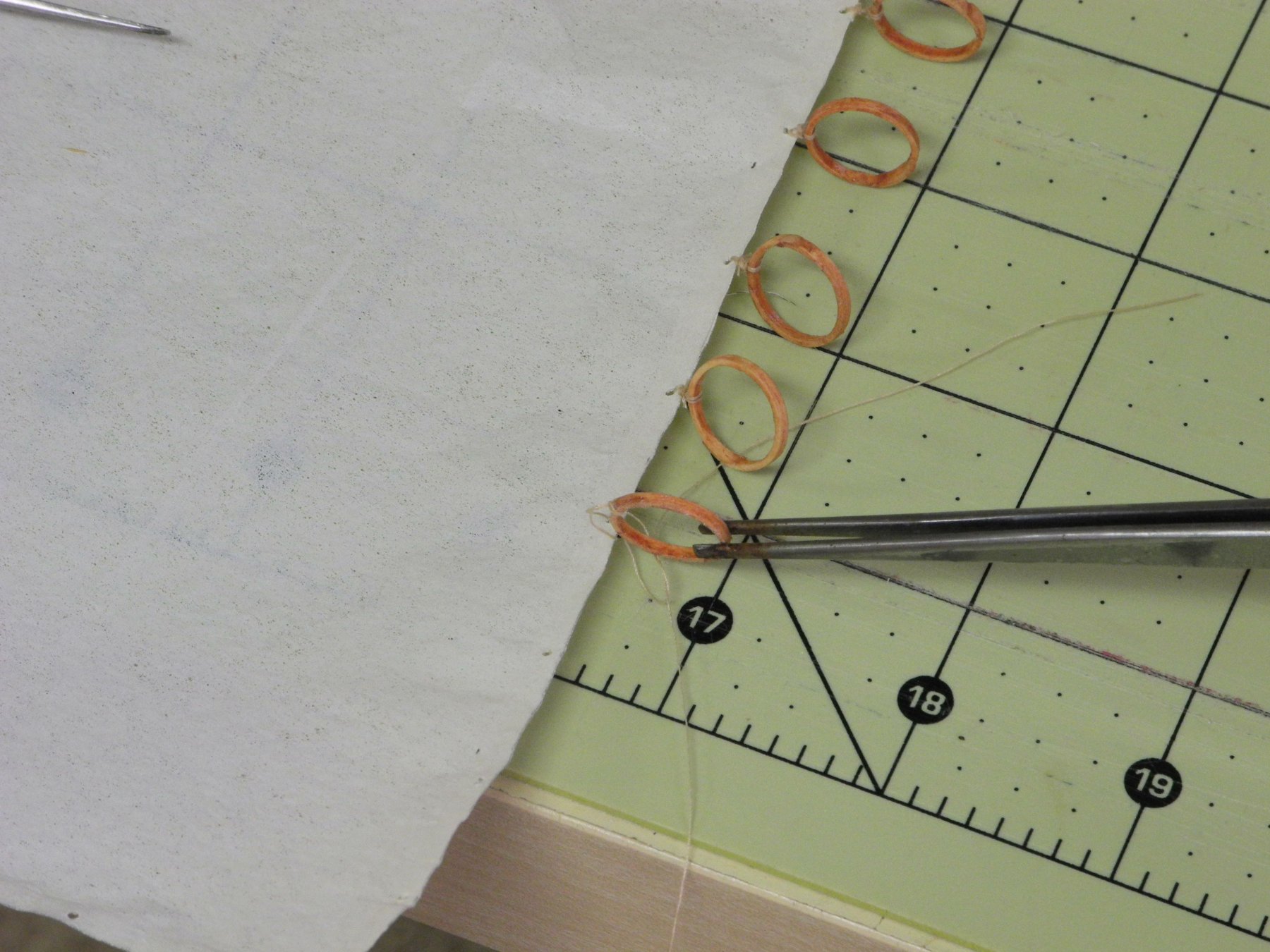
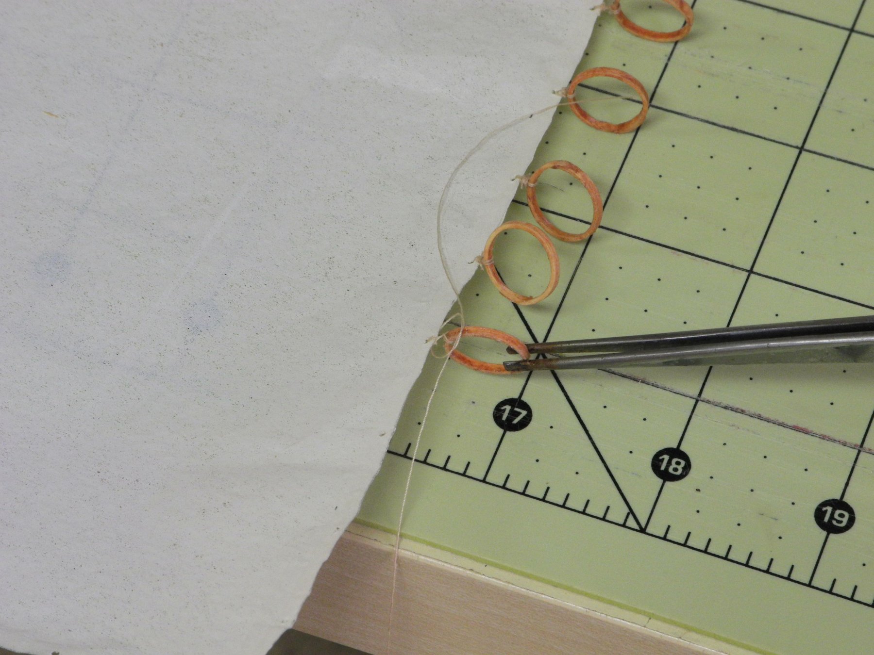
The mainsail was then laced to the boom by running the lacing line through the ringbolts and the ‘grommets’ on the sail. (These grommets had been formed by punching a hole through a spot of white glue that was positioned on the sail).
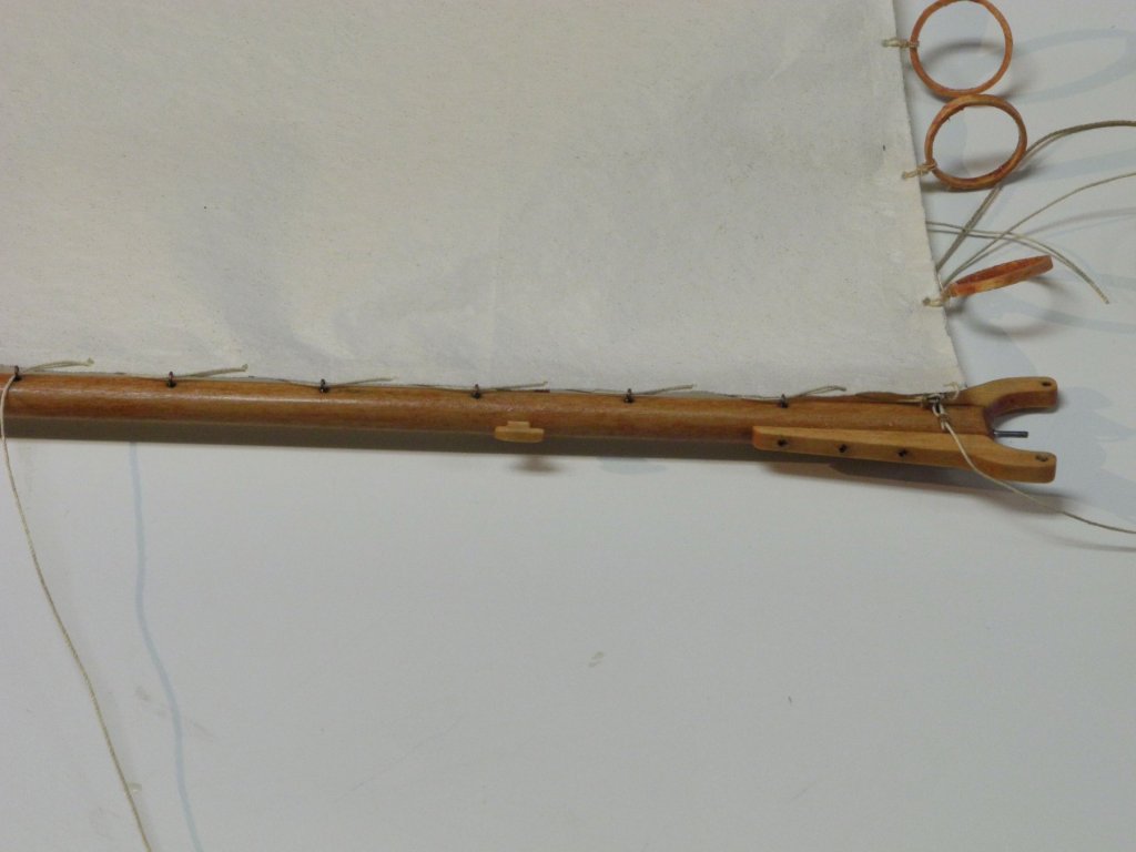
The sail/boom combination was installed by sliding the mast hoops down the mast, and then positioning the boom in its proper location, held by the pin that is between the two jaws.
As can be seen in the above photo, the mainsail is trimmed smaller than the actual measurements to prevent the furled sail from appearing too bulky.
The next post will address installation of the topping lift.
Thanks everyone – it’s good to be back at work!
-
-
Hi Patrick - just catching up again. That tender will look really nice. I'm continually amazed at the scale you're able to work in.
- popeye the sailor, Piet and mtaylor
-
3
-
Hi Everyone..
I'd like to wish you all a very Merry Christmas and a healthy and Happy New Year.
There's been no progress on Kathryn since September, due to the serious issues we've been dealing with. However, all of the daily doctor visits and treatments have come to an end and we're starting to get back to our normal happy lives again. I'm hoping to get back to Kathryn's rigging in the near future.
In the meantime, thanks again for all of the wonderful comments on the build, and I'm looking forward to being active on MSW again.
Best regards to all!
- thibaultron, druxey, cog and 11 others
-
14
-
Hi Patrick - just catching up after being 'gone' for a while. Really nice progress.
-
I agree about the micromotor. I have a Marathon model - fairly expensive but I used it for years when I was bird-carving and it has been really valuable in the ship modeling. Any micromotor should have a foot pedal for optimum control. Less expensive micromotor options are available on eBay, but I don't know anything about their durability.
- John Allen, Canute and Landlubber Mike
-
3
-
Welcome back Brian. I'll be following as time and circumstances permit.
- Seventynet, GuntherMT and Chuck
-
3
-
Hi Patrick
Just checking in after a prolonged absence and very impressed with the progress on Genesis. Bravo!
- cog, mtaylor, popeye the sailor and 1 other
-
4
-
UPDATE
Hi Everyone. I'm sorry that it's been quite a while since my last post. We've had some serious issues at home lately, and my focus has been there rather than modeling. These issues will continue for the foreseeable future, so I'm not sure how much modeling time (or focus) I'll have. If I do make some progress on Kathryn I'll continue to post updates.
Thanks everyone for all of your 'Likes' and comments through the build - they have meant a lot to me.
- thibaultron, ccoyle, Jack12477 and 7 others
-
10
-
-
Hmm - that's interesting, Ron. I looked back at all of the photos I have of Kathryn and didn't find any furled sails that look like that.
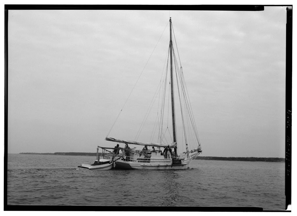
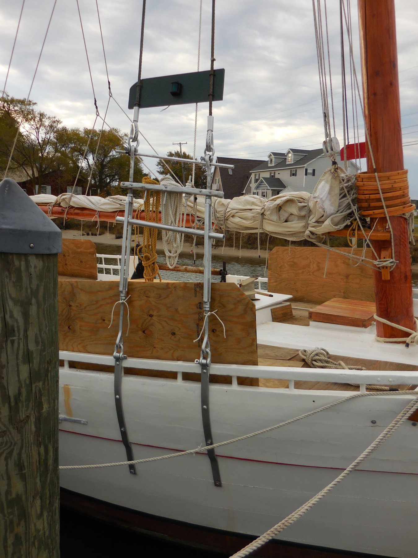
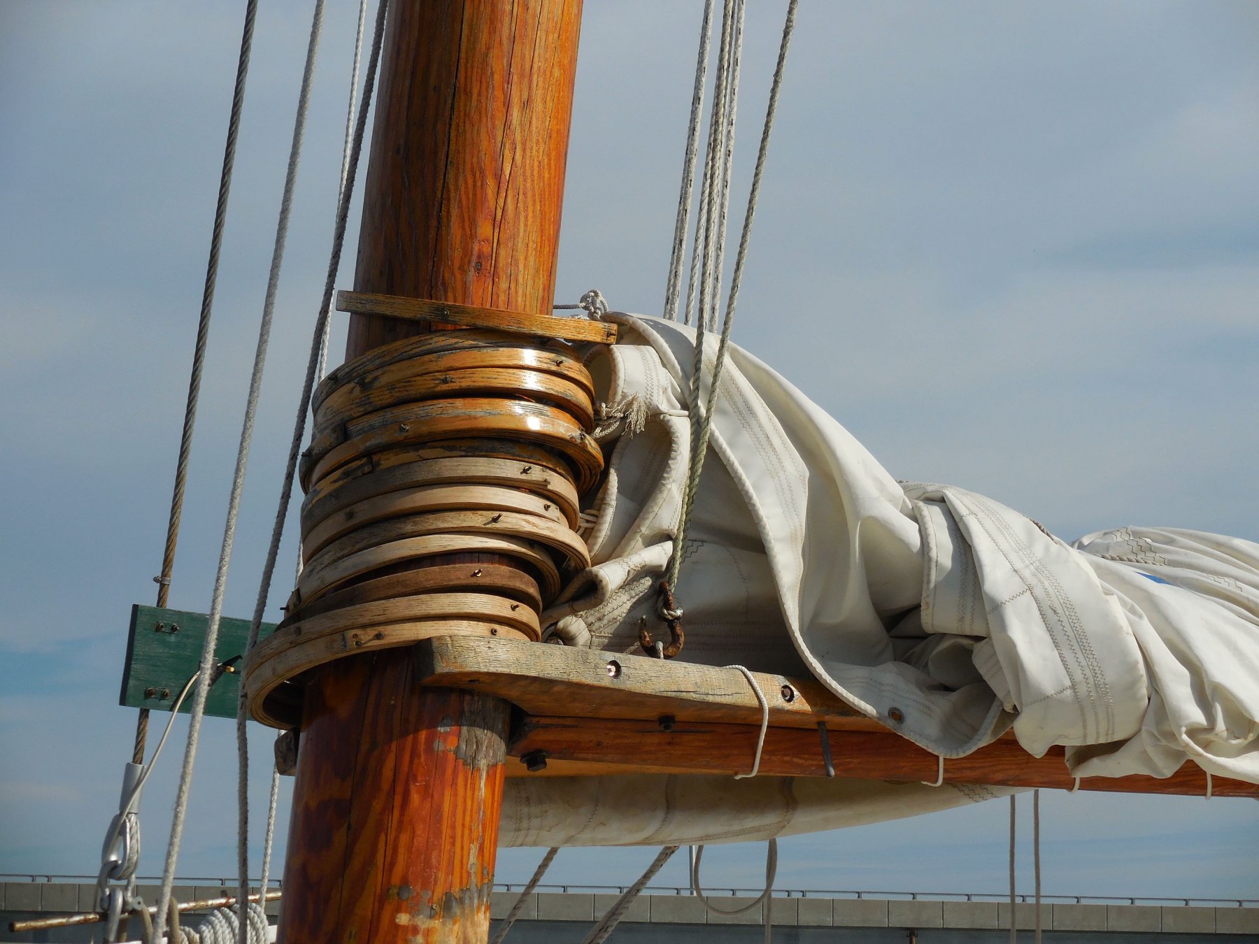
Here's a photo that was taken during the HAER survey during the 1990's:
Here are a couple I took in 2015, right after her rebuild:
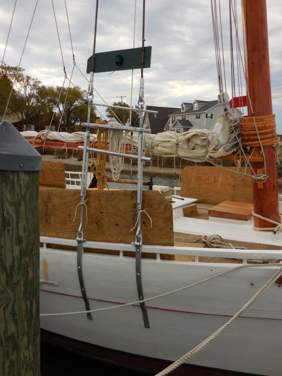
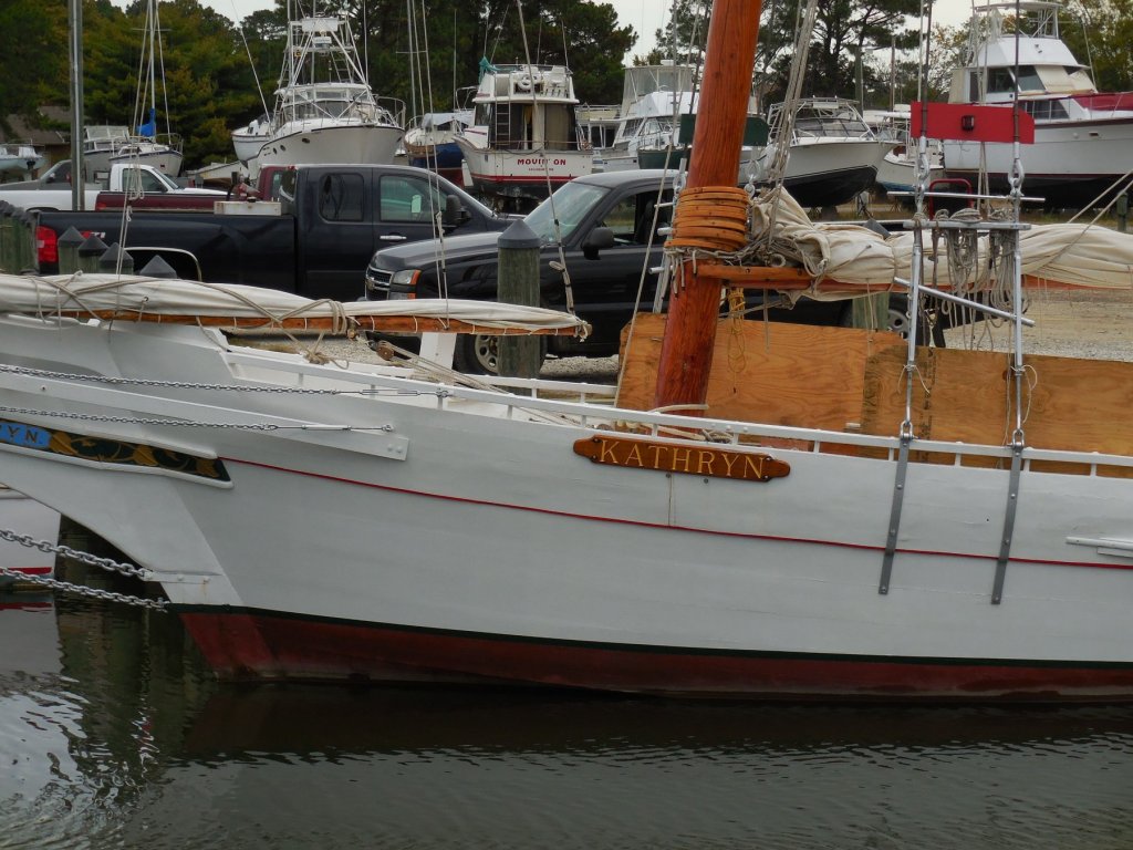
And here are a couple I took in 2017 during my last visit to Kathryn:
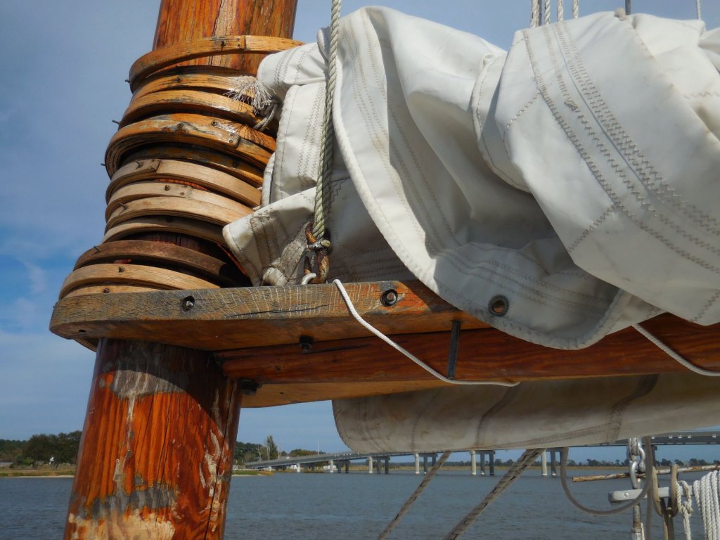
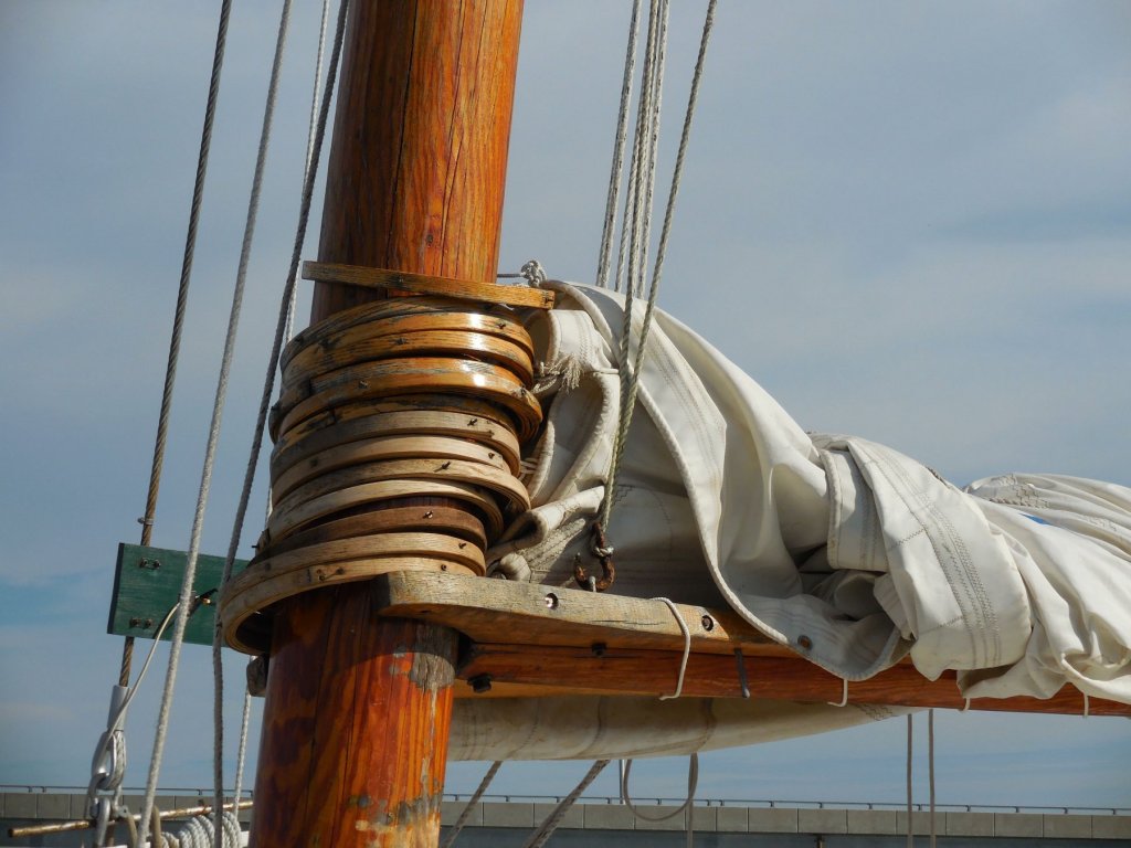
Also, I took a quick look through the book "Working Skipjacks of Deal Island" - all of the skipjacks shown in the hundreds of photos are operating under power from the yawl boats, so they all had furled sails (or no sails in one instance) and none showed the arrangement you're referring to.
So, I'll be leaving things the way they are.
Thanks.
- popeye the sailor, mtaylor, JOUFF and 6 others
-
9
-
Kurt - thanks for your kind words. Both hobbies - ship modeling and bird carving - have their own unique challenges and have been very satisfying for me. I'm still learning and don't consider myself a 'master' by any stretch of the imagination, but I'm enjoying the whole experience.
Druxey - thanks! Your sail-making supplement answered a lot of questions for me - without it I don't think I would have attempted to put sails on Kathryn.
-
Part 82 –Mainsail cont’d
After creating Kathryn’s main sail, it was easier to install the mast hoops on the sail before bending the sail to the mast.
Kathryn’s lower mast hoops are attached to the sail using a jackline that runs through the lower grommets, allowing the mast hoops to move up and down with some flexibility. The upper mast hoops are seized directly to the sail.
Since the sail will be furled, I decided to seize all of the mast hoops directly to the sail using some light thread. The first action was to secure the mast hoop by running a loop around the hoop and running the loose ends through the loop.
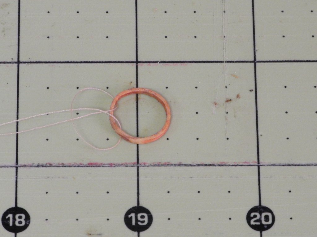
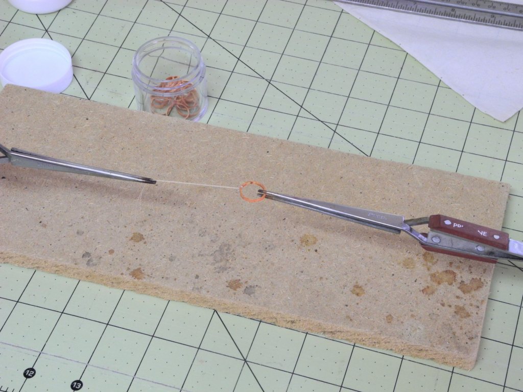
The loop and loose ends were pulled tight and then were held using a couple of third hands, and the line was fixed in place using some matte medium.
After the knot was set and with the mast hoop held perpendicular to the sail, the two loose ends were run through the sail from either side.
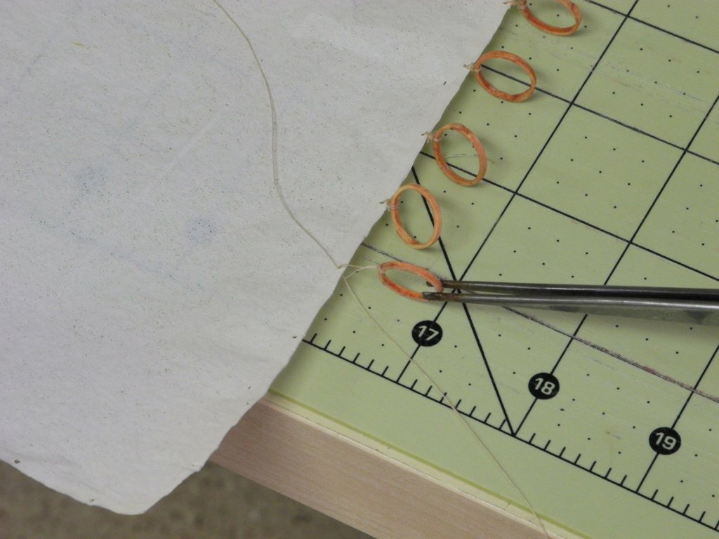
The two lines were tied in a knot below the mast hoop.
And then the loose ends were brought above the hoop and tied again.

The process was repeated, tying knots below and above the hoop at least once more, and then the knots were painted with matte medium to secure them.

After the medium had set, the loose ends were trimmed.
After all of the hoops were attached, the lower double block for the main halyard was seized to the head of the sail.
Finally, lines for securing the lower corners of the sail were seized to the tack and clew.
The mainsail is now ready for installation on the model, which will be covered in the next post.
Cheers everyone!
-
Part 81 –Mainsail
Kathryn’s sails will be furled, so I decided to use silkspan for the sails to reduce the bulk of the sails. David Antscherl offers a very good process for using silkspan in his Swan IV Sail Making Supplement, and I used some of his suggestions in making the mainsail.
I found a good source of silkspan – Brodak Control Line Flying. They offer a medium weight and a lite weight version, and both come in packages containing 2 24” x 36” sheets.
http://brodak.com/catalogsearch/result/?q=silkspan&x=0&y=0
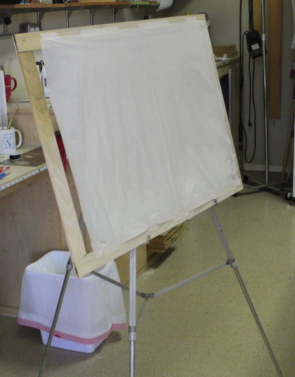
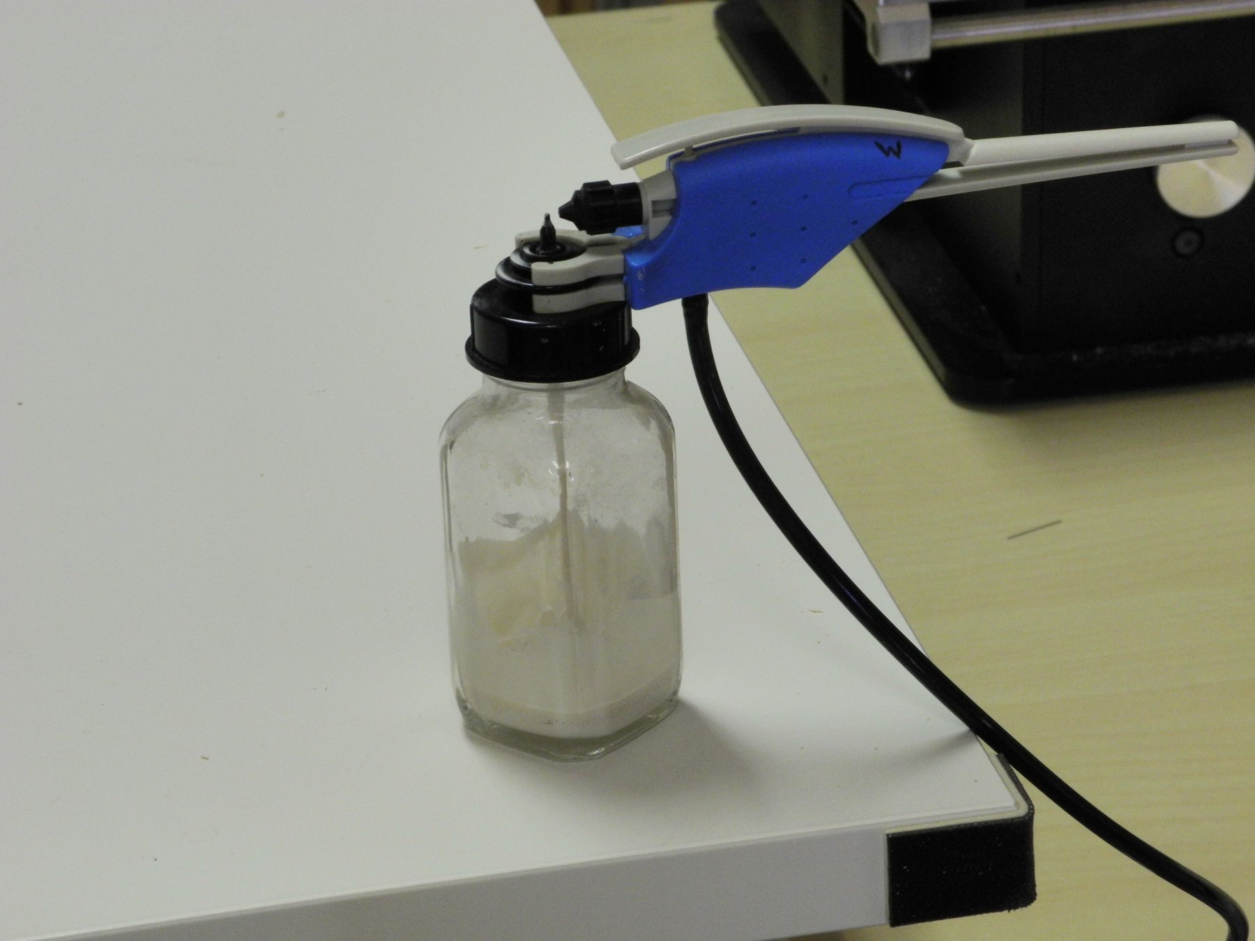
The first step was to build a frame that would hold a large piece of silkspan. I mounted the silkspan to the frame using chart tape, and then held the frame vertically in an old artists easel.
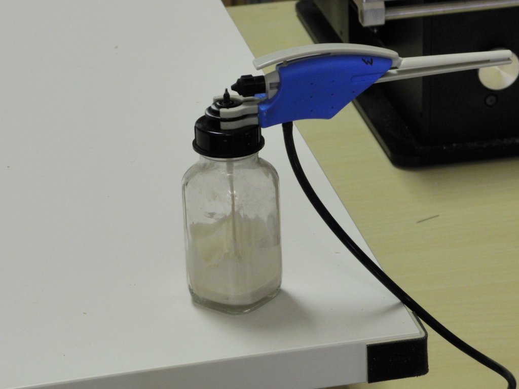
Following David’s suggestions for painting the silkspan, I mixed acrylic titanium white and raw umber to give an off-white color, then diluted the paint so that it could be used in an airbrush. I have a couple of cheap single-action airbrushes that gave a nice broad spray for coverage.
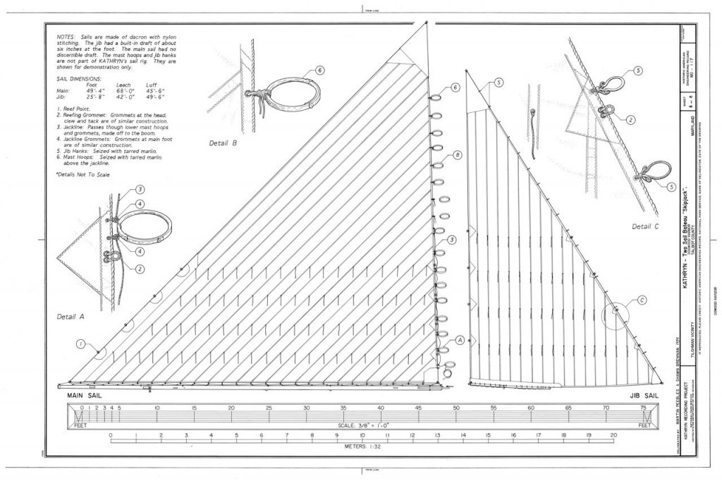
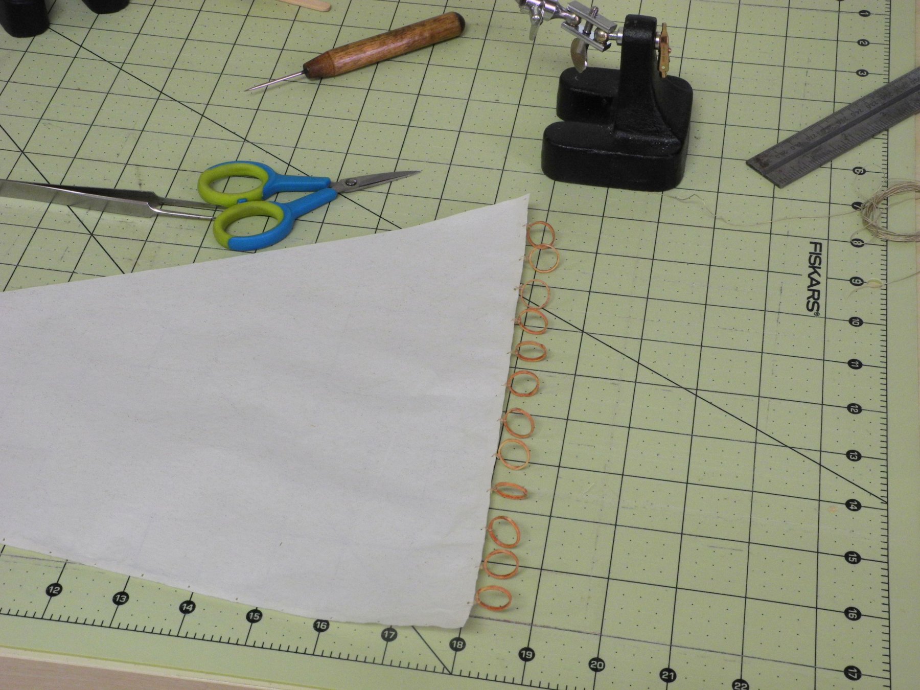
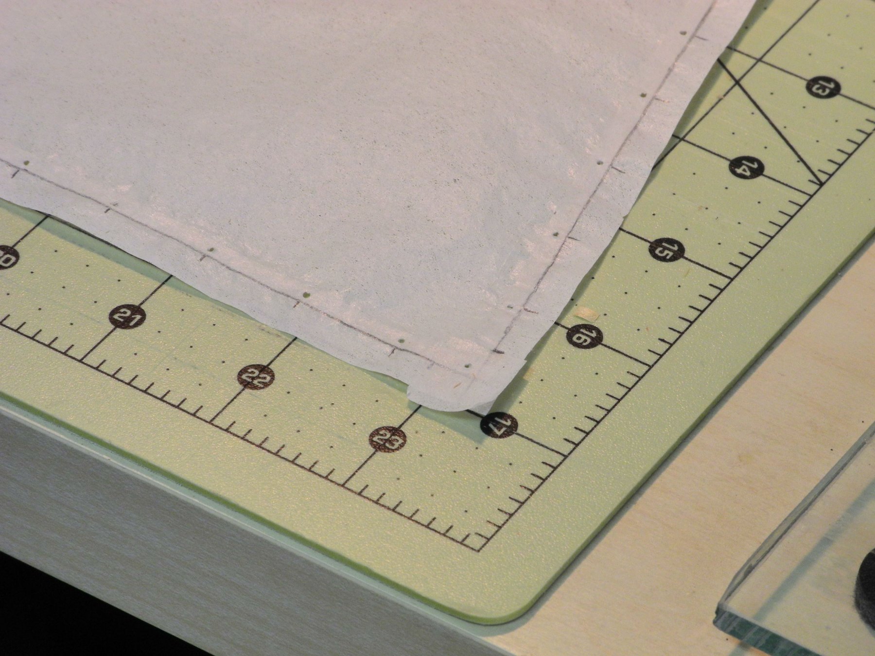
Cardstock was used to make patterns for the sails based on the drawings of Kathryn’s sails in the HAER documentation. These patterns had the locations of all of the grommets for mounting mast hoops and other rigging details marked where appropriate.
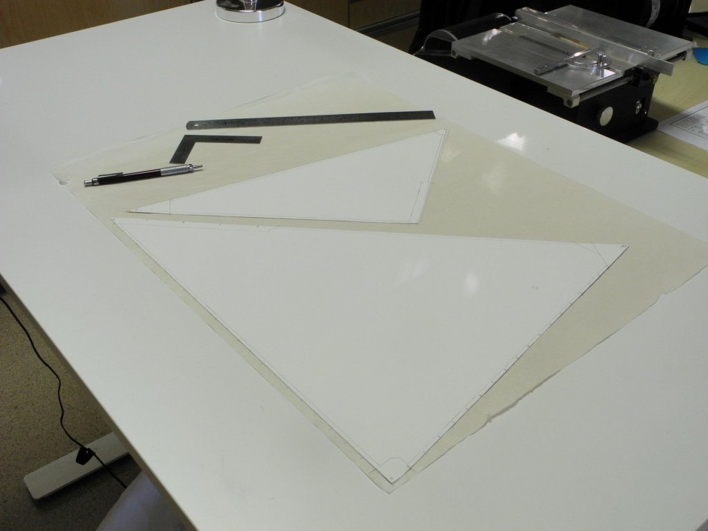
Using the outside of the pattern as a guide, the outline of the sail was drawn on the silkspan and the location of all of the grommets and reinforcing pieces was marked OUTSIDE the boundary of the sail. Making the marks outside the boundary enabled me to keep the actual sail clean and free of pencil marks. The sail was cut out leaving enough excess to still show these marks.
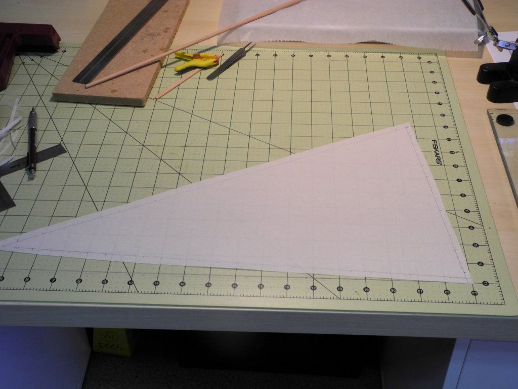

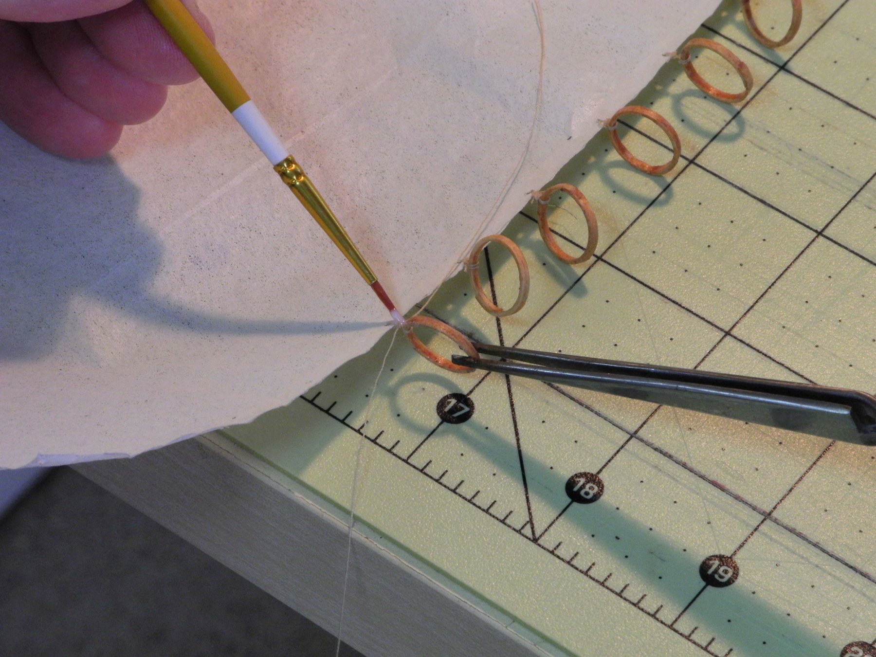
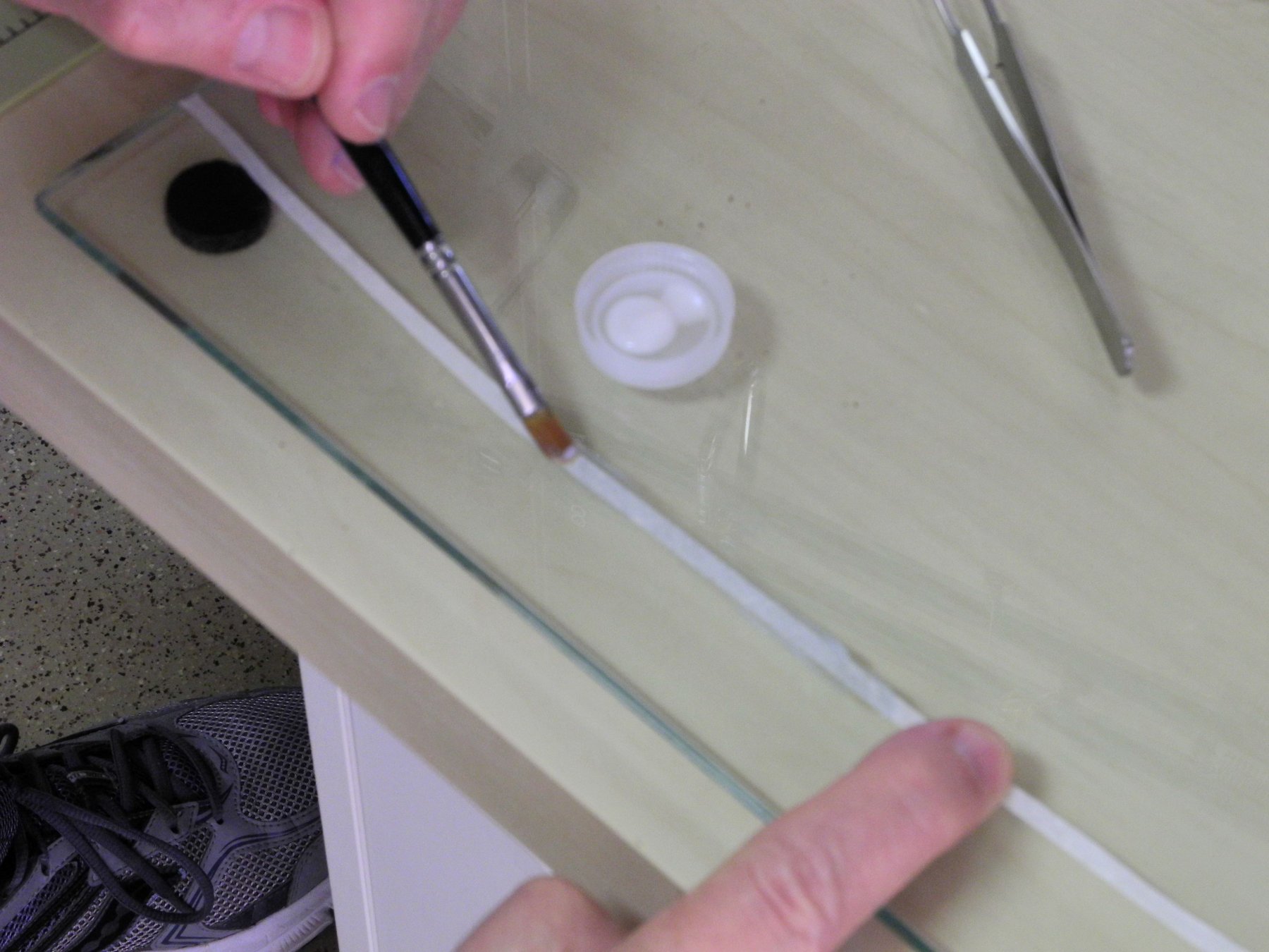
Reinforcing strips of silkspan were cut for the areas that would have lines attached. These strips were stuck onto the silkspan using acrylic matte medium. The medium was applied to the strips using an artist’s paintbrush and then while the medium was still wet the strip was attached to the sail. More medium was brushed over the strip to ensure a good bond. The matte medium remains flexible after it has dried.

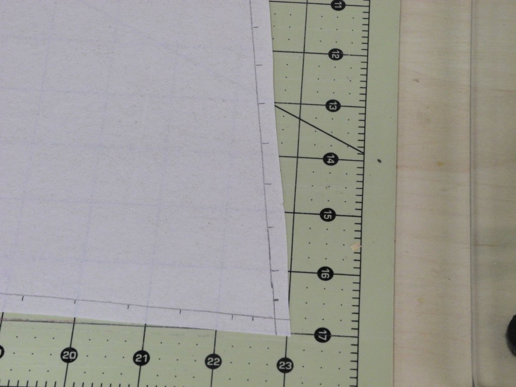
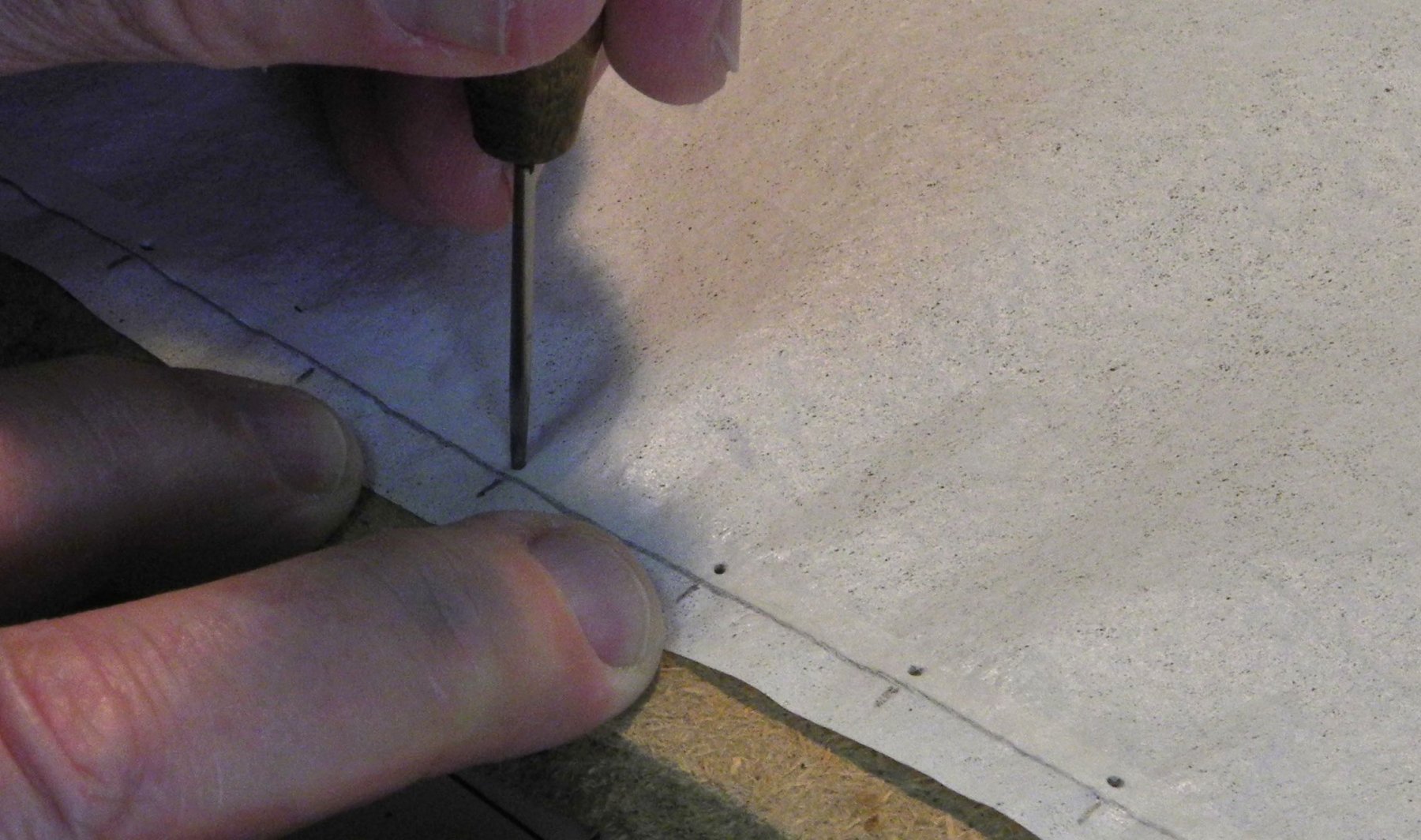
After the reinforcing strips had set, a small awl was used to punch holes in the sail’s perimeter as indicated by the pencil marks that had been made previously.

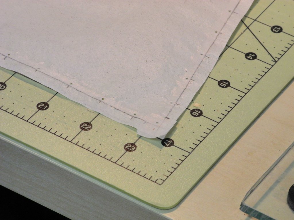
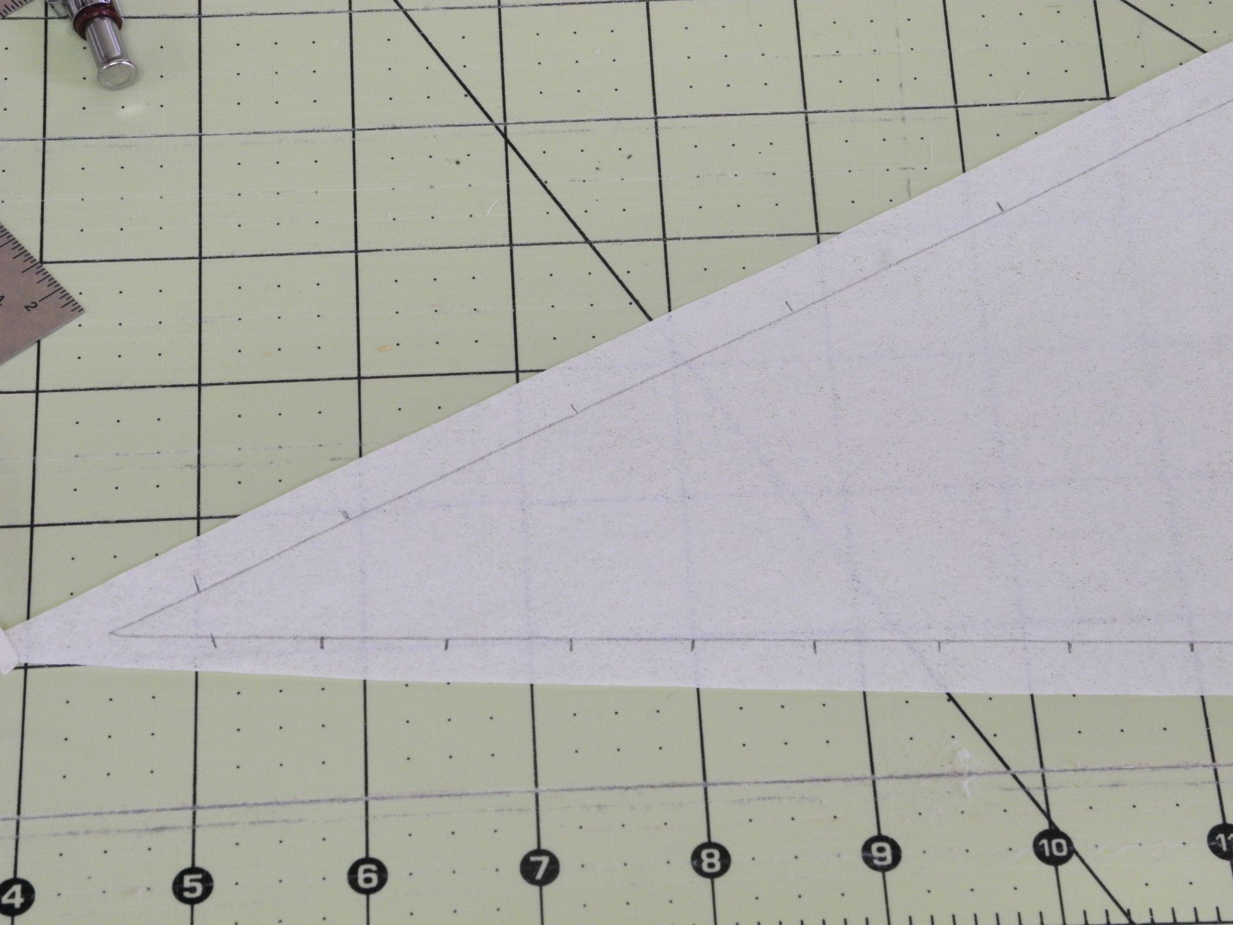
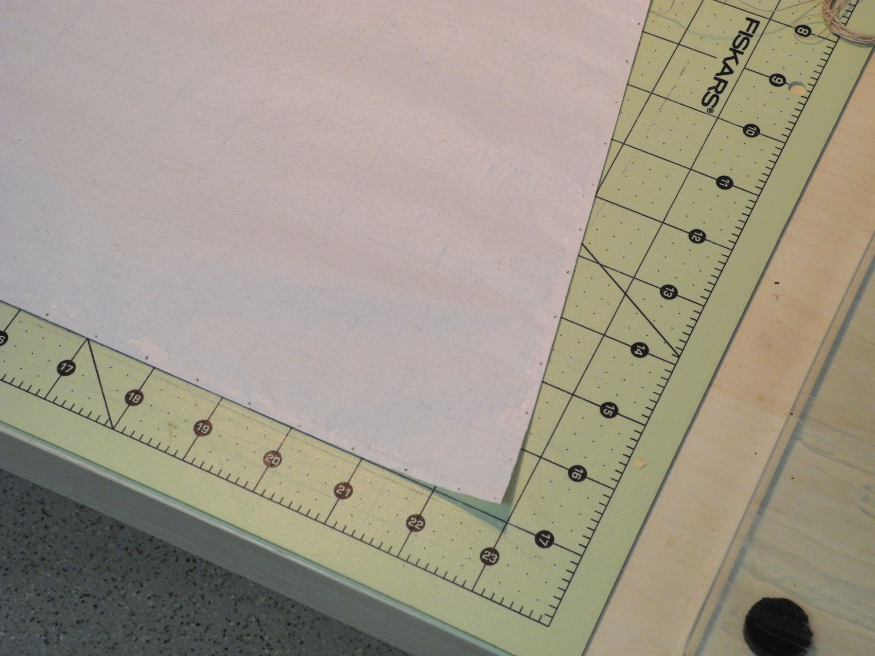
The sail was then trimmed just inside the border line to arrive at the final correct size.
Because the sails will be furled, I decided to make both the mainsail and the jib somewhat smaller than the full sails. The mainsail is about 2/3 of the height of the full sail, while the foot of the sail remained at the correct length. Also, due to the furling, I didn't try to make any of the seams on the sail.
The next step is to install the mast hoops and other connections on the mainsail, which will be the subject of the next post.
Thanks everyone!
- PETERPETER, JOUFF, thibaultron and 12 others
-
15
-
Part 80 –Rigging Plans
Kathryn’s rigging is fairly simple, especially as compared to square-rigged ships. However, there are still opportunities to cause rigging problems by performing some of the work before other components that should be installed first. Avoiding this situation requires a bit of planning to understand the sequence that will work best.
The first step was to develop a description of each line, including rope and/or wire required, the termination points of the line, and the route that the line would need to take. This was developed as a Word document. The following is an excerpt from the document, describing the Topping Lift.
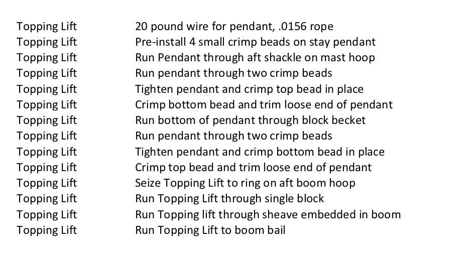
The next step was to identify each task required to install the particular line or component, as in the following excerpt, and to build these tasks into a spreadsheet.
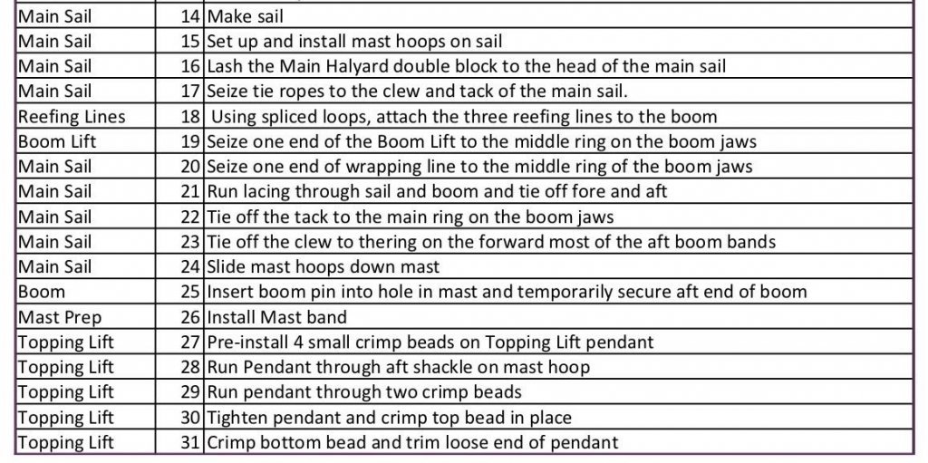
A sequence of tasks was then put together, where the tasks were numbered in the sequence that they should be performed, blending tasks from the various components or lines where it made sense to do so, and then sorting them by the sequence numbers. The following excerpt shows a portion of the resultant plan.
I’ve attached the Rigging Details and a sorted Rigging Plan as PDF’s for those who may be interested in seeing these documents in their entirety. I fully expect that some changes will be made as work progresses, but these are good overviews of what needs to be done.
- usedtosail, Canute, GuntherMT and 6 others
-
9
-
Hi Kurt - glad you're on board - better late than never! Now, I'm looking forward to your Newsboy build (right?)
-
Hi Mark. Yes, the main halyard runs to the starboard cleat, and the jib halyard runs to the port cleat.
- mtaylor, thibaultron, Canute and 1 other
-
4
-
3 hours ago, John Allen said:
Frank,
I look at your build, and always see something I missed, and when I compare it to the pics of the real thing I am amazed every time I open this site. Your attention to details is just spot on even down to the small cracks running up and down the mast.
Absolutely superior craftsmanship. There are a lot of skill sets your passing down us builders in training or should I say apprentices, or wanna bes'
") . Kudos.
. Kudos.
Thanks, John. This build has been a good learning experience for me, and I'm glad if others are benefitting from it as well.
2 hours ago, druxey said:Lovely work as usual, Frank. Real mast wedges are something rarely seen on a model!
Thanks Druxey. Since I have lots of photos of the real thing I decided to try to have the model as realistic as possible - including the mast wedges. I have to admit, though, that it took a while to work up the courage to step the mast. Now, after the fact, I don't think it was too difficult.
2 hours ago, EdT said:Nice detailing, Frank.
Ed
Thanks Ed - as I mentioned above, the many photos have been a real help.
1 hour ago, Kurt Johnson said:Frank,
Very precise work!
Kurt
Thanks Kurt!
- cog, popeye the sailor, mtaylor and 5 others
-
8


Kathryn by Mahuna - FINISHED - 1:32 - Skipjack Based on HAER Drawings
in - Build logs for subjects built 1901 - Present Day
Posted
Thanks Michael. I hadn't thought of using the heat shrink tubing, but it's probably worth a try. Thanks for the suggestion, and I'll try it out in the future. For now, since I have the crimping beads and don't have appropriate shrink tubing, I'll proceed as planed.
Thanks Kurt. Hopefully things will proceed from here - we're pretty much on the home stretch with Kathryn.
Hi Rich. Thanks, and good luck with your move. Looking forward to seeing your new shop one of these days.