


JeffK
-
Posts
29 -
Joined
-
Last visited
About JeffK

Recent Profile Visitors
725 profile views


-
 Daniel KF reacted to a post in a topic:
American Fishing Schooner by JeffK – Constructo U604 kit - Scale 1:64 (approximate) – First Build
Daniel KF reacted to a post in a topic:
American Fishing Schooner by JeffK – Constructo U604 kit - Scale 1:64 (approximate) – First Build
-
Daniel KF reacted to a post in a topic:
American Fishing Schooner by JeffK – Constructo U604 kit - Scale 1:64 (approximate) – First Build
-
JeffK reacted to a post in a topic:
A guide to making anchors - 1906
-
etubino reacted to a post in a topic:
American Fishing Schooner by JeffK – Constructo U604 kit - Scale 1:64 (approximate) – First Build
-
etubino reacted to a post in a topic:
American Fishing Schooner by JeffK – Constructo U604 kit - Scale 1:64 (approximate) – First Build
-
Canute reacted to a post in a topic:
Scale sizes for building
-
mtaylor reacted to a post in a topic:
Scale sizes for building
-
Thanks to all the contributors on this thread. I know I’ll be using this info when I, eventually, start rigging my schooner!
-
thibaultron reacted to a post in a topic:
Looking for some insights into how a basic cabin would be framed in real life (early 1800's)
-
bruce d reacted to a post in a topic:
Looking for some insights into how a basic cabin would be framed in real life (early 1800's)
-
mtaylor reacted to a post in a topic:
Looking for some insights into how a basic cabin would be framed in real life (early 1800's)
-
Not sure this would help you, but for my 1900 - 1910 vintage fishing schooner I found the Ernestina restoration website a great resource (http://www.ernestina.org/) . Their main cabin shows the wall planks run horizontal with dove tail connections at the corners.
-
JeffK reacted to a post in a topic:
An Introduction to Seahorse Kits: Duyfken, Sao Gabriel, Leudo Vinacciere, Armed Virginia Sloop
-
Exploring FreeCAD for ship modeling
JeffK replied to TonyM's topic in CAD and 3D Modelling/Drafting Plans with Software
Impressive. I’ve used some cad in my original layouts, but not anywhere this level of detail. Looks great. -
jfesterman reacted to a post in a topic:
Harvey 1847 by jfesterman - Artesania Latina - 1:50
-
I will be looking in. I’m also working on an old kit, so I wonder if we will have similar problems with older materials.
-
JeffK reacted to a post in a topic:
RR Tug Model
-
 JeffK reacted to a post in a topic:
USS Tennessee 1869 by Keith Black - scale 1:120 - Wood Hull Screw Frigate - ex Madawaska 1865
JeffK reacted to a post in a topic:
USS Tennessee 1869 by Keith Black - scale 1:120 - Wood Hull Screw Frigate - ex Madawaska 1865
-
Thanks for the help and support. The kit might have been easier, but what I’m doing now, I think, is more fun.
-
Flags supplied by Amati look to be too big
JeffK replied to DaveBaxt's topic in Masting, rigging and sails
Have you ever tried to print some of the sail details this way? -
I need to come back to your log when I get to rigging my model. Yours looks great.
- 778 replies
-
- 1
-
-
- cheerful
- Syren Ship Model Company
- (and 1 more)
-
First time I’ve looked at your build. I am more then impressed.
- 950 replies
-
- 1
-
-
- syren
- model shipways
- (and 1 more)
-
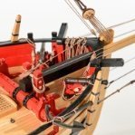
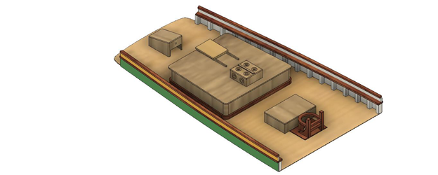
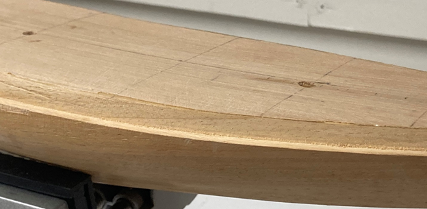
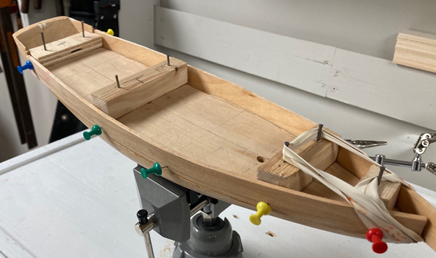
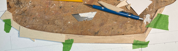
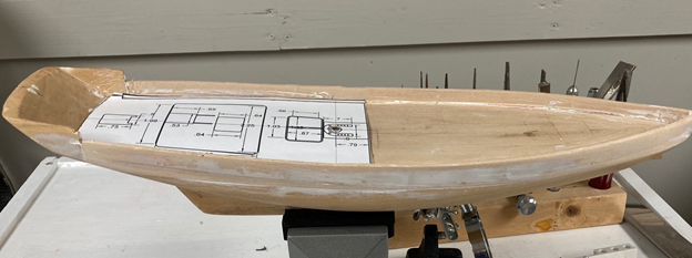
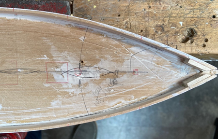
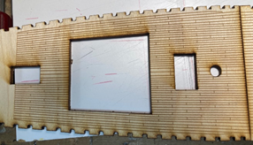
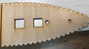
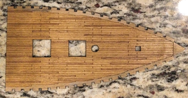
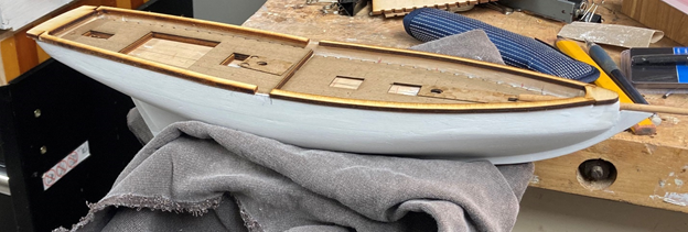
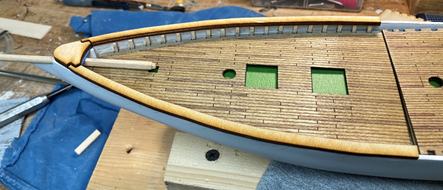
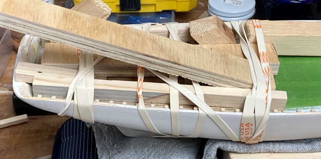
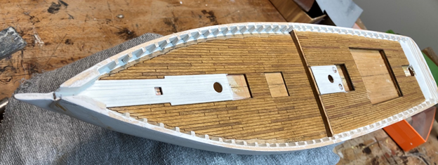
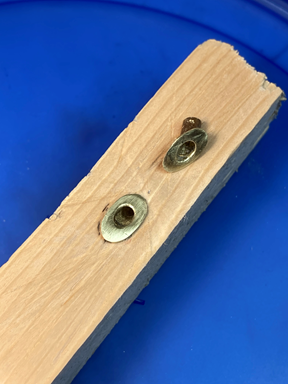
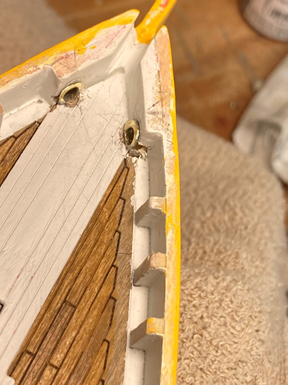
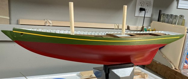
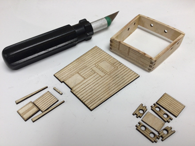
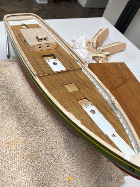
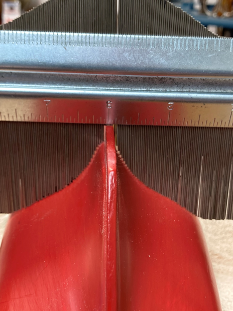
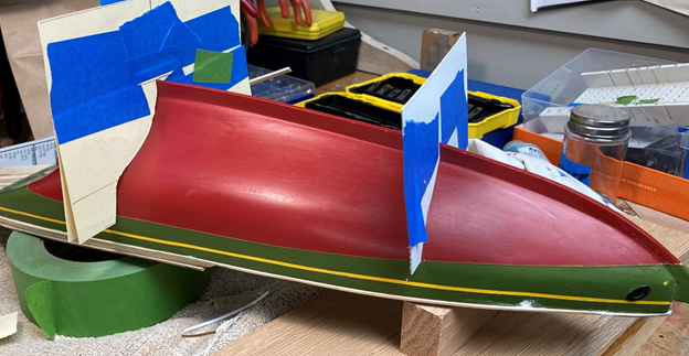
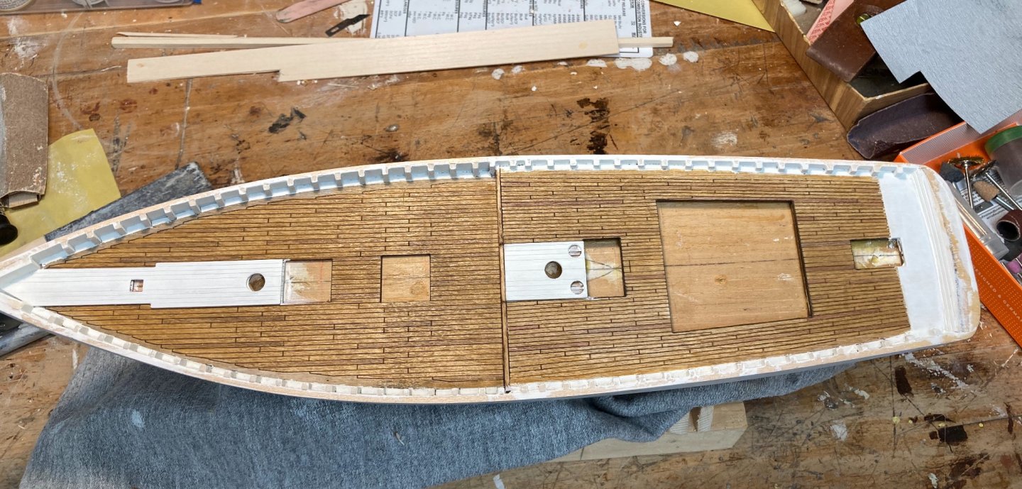
Constructo Schooner Blog – Second Installment; 05-20-21 Hi everyone. It’s been over a year since I last made an entry into this log. I have worked on my model during the pandemic, as much as I could manage with everything else that was going on. I have been following along in the forum and searching for solutions to some of my learning curve issues. I want to thank all of the other people that have been working and posting in the forum. This has been a wonderful source of information! As part of the design process, I read Chappelle’s “The American Fishing Schooners”, and looked at many of the Schooner models on this forum as well as Internet searches for real schooners reviewing how the decks were arranged, details and spacing of the deck furniture. the results of some of this are shown on the deck laser cutouts. The “Schooner Ernestina” web site was especially helpful since they showed some good, detailed, construction pictures of their rebuild. I had decided that most of what was above the waterline on the original Constructo kit would need to go. It just didn’t fit with what I could figure out would have been historically more accurate for the time frame and scale that the actual model hull shape seemed to fit (1890 – 1910 time frame; and 1:64 scale). I also wanted to design much of the new deck furniture in 3D (working with Fusion360) and do the fabrication using some of the equipment in my local library (Laser cutter, Carvey CNC, etc.). I had mixed results with taking the 3D designs from Fusion360 and translating them into the file formats needed for the laser/Carvey machines. I found out (from this forum) that the free version of Fusion360 no longer supported the file types I needed. Also, I found that Fusion360 was frustrating for me to work with. This resulted from the capabilities of my PC, the download rates I was receiving from my Internet service provider, and the fact that Fusion360 is accessed via the Internet leading to a fair number of crashes and freezes. Fusion360 did get me to a good 3D layout, with a good idea of the final deck furniture sizing. This is a shot of what the Fusion 360 stern design looked like. Based on reviewing this layout, I changed the cabin size (made it smaller) and shifted some of the other furniture a bit. I ended up doing all the final layouts in 2D, using InkScape, the free software that my library uses to do the Laser Cutter files. One of the first things I needed to do, was to remove the original bulkheads from the original model hull. To carve them down to a better thickness, especially in 40+ year old dry wood, was not practical. So, I cut off the original bulkheads, and then carved out the side of the boat to accept new dimensioned wood bulkheads. One regret, I made them from basswood, and I wished I had used Baltic birch plywood. I also left the stern section. I wasn’t sure I was willing to tackle adding on a new stern, especially since this would have meant more research into what I should put back! \ I also wanted to add a false keel to the model. I did a template for the hull and cut the keel from basswood. This is what the model looked like after the new bulwarks with the Fusion360 deck layout, without the false keel. One of the interesting discoveries I made relative to the original hull, that it was not symmetric, and the predrilled mast holes were not centered. I decided not to try and make the hull shape symmetric. This this was not very visible on the model, and realistically my skill levels might make the final results worse! I did recenter the mast holes. These were visibly out of alignment with the hull. The following picture gives a view of the recentering approach, as well a view of the new bulwarks. The next step was to work with my local library to do the laser cutting. Doing this during the pandemic was inconvenient. I could not walk in and manage the laser cutting. I could use the stock of library wood, but if I needed to use mine (especially the thinner stock I wanted to use for the decking and deck furniture) it had to be quarantined before the library staff could work with it. Initially the quarantine period was 2 weeks. The Library staff were great to work with, but it just added a lot of time to the process. The next pictures show the fore and quarter deck as the came off the laser cutter. These were on the thicker stock library wood. I also decided to precut the locations for the bulwark stanchions. I felt that this would give me better control of their spacing. I printed the deck planking in several thicknesses, from 1/32” (fore deck and quarter deck) to 1/16” and 3/32” for the quarter deck. I was looking for the equivalent of a 9” to 12” real height difference between the fore and quarter deck which I achieved by layering several of the laser printed quarter decks, picking the better-looking laser cut, for the top layer. Using several layers also let me more easily bend the decking to conform to the deck camber. Part of this process that I enjoyed was the staining and painting of the decks. The following is an intermediate picture, before I had decided how to treat the waterways (not sure of the terminology). I also laser cut the rails. The following shows the first pass at the laser cut rails, in the thicker library plywood. The quarter deck rails intentionally did not meet the maindeck rails. I figured I would need to hand carve the curved part where they join. I’ve also laid in the laser cut decks and the raised “king planks” around the masts. This version of the rail designs did not include the pin rails. They were added to the final laser cut` design. At this point I’ve got the false keel installed and the hull about midway in the priming sanding stages. In someone’s build log in the forum, I remember reading that the most useful modeler tool was sandpaper. I know I’m using it more than I originally imagined. This is finally starting to look like a boat. The next steps involved gluing in the bulwark stanchions. These were fitted in the laser cut spots on the decking, with the decking dry fitted on the boat. This shot shows the first pass at the railing balanced on the bulwarks. Also, the bowsprit is dry fitted. One problem that surfaced when I installed the final rails (somewhat narrower then the first pass) was that I had not tapered the stanchions. So, I needed to shave the upper parts of most of the stanchions. This was after I had painted everything of course! The following shows the quarter deck being glued down. Note the carefully crafted gluing jig. The following shows the decks installed, stained, and painted.,. The next step was going to be to paint the hull. As I have read in other building logs, I now realize that, at least for me, painting the hull, and then touching up the paint, is probably a continuing process that will finish, maybe, when I finish the boat. As I started the multiple coats of paint, I also started to work on some of the details. One of these was fabricating the hawse pipes. The following picture show the jig I used, as well as the final pieces. These were blackened later. The second picture shows the inboard part of the hawse pipes being dry fitted. I’m doing all the painting by hand. I can paint ok with a spray can, but I don’t have, and didn’t want to learn how to use a spray gun. So far, I’m happy with the results. I did do a lot of masking in the process. The accent stripe was achieved by using the narrowest pinstriping tape I could find, after painting the hull in that area in yellow. I then painted the overall topworks as shown. I was a bit concerned with how well the line would hold, and if I would get any significant paint bleed. The pinstripe tape came of easily and cleanly. The next several steps were to design & laser cut the final rails, cabin, and cabin parts, and fit them together. When I designed the cabin, I included finger joints for the corners to facilitate fit up and strength. These worked well. The following shows the cabin structure, and the remaining parts for the skylight and hatchway. The skylight also has finger joints. The following shows how these pieces look assembled. It also shows the status of the rails. These are mostly done but need to be painted. This also shows the stanchions I needed to bevel which also need to be painted, again. I included the pin rails as part of the laser design, including predrilling the holes for the belaying pins. If you look closely on the starboard side of the cabin. I have a porthole that I’m working on. It is a filed down (in my drill) from a 1/8” aluminum pop rivet. I blackened it using the brass black solution. It works well re scale, and it is turning out fine. I would prefer to work with a brass pop rivet, which I would probably leave brass, but I could not find a source for them. Plenty of steel, aluminum, and some copper which I thought about using. It would probably blacken better. But I don’t think enough to change from the aluminum which I already have. The darker circles on the monkey rail are where I pinned the rail through the monkey board, into the bulwarks. These will be cleaned up as part of the painting process. I also decided that I should work on the final stand. I do not have a drill press and have been thinking about how to drill through the false keel to mount the model. I eventually decided to design the base, have the base cut by the library’s CNC Carvey, including the centering holes through the base. I could then turn the boat over, and drill through the base into the false keel and hull. At least that is what I hope I can do. The following shows the contour gauge that I used for this (and other layout issues). I inherited it from my father. it must be 70 years old. Still works. I then went to cut cardboard templets to eventually convert into sketches that I could scan and import into InkScape and eventually into Easel, the software used to generate Carvey files. That mostly brings me up to date. I need to finish the base, drill the appropriate holes for mounting the boat, then touch up the hull and deck (I am a clumsy builder, and the boat shows this). Then I need to paint the cabin and laser cut, assemble, paint the rest of the deck furniture.
- 5 replies
-
- 5
-
-
- Fishing Schooner
- Constructo
- (and 1 more)
-
I love what you have done with this model. When I first looked at it, I took it as something I could aspire toward, but probably would not be able to reach. Having worked on my schooner for a year now (very slowly) I know that the “aspire” ain’t ever going to happen! Your level of detail and quality is really good!
- 139 replies
-
- 4
-
-
- benjamin w latham
- model shipways
- (and 1 more)
-
Sorry for the late reply. I just noticed I had a red highlighted icon in my forum page and realized it was your reply to my post. I find this thread fascinating, and the information very good! I appreciate the confirmation that I couldn’t save the DXF files from the free version of Fusion360. I actually did look at having some of the 3D print shops around where I live to check into printing 3D files, but that was in the middle of COVID, and many of the shops were either not open, or at least not responding to phone calls. I decided that, for what I was doing, it wasn’t worth the time, then. I also wasn’t willing to invest in buying a higher end 3D printer for what little printing I would be doing. COVID has also complicated working with my local library. They have been in and out of “contactless” support. Basically I can email the files, but they can only print using their wood stock. Mostly their stock are in thicknesses that I can’t easily use.
-
I just ran across this thread and found it fascinating. I’ve been working on an old wooden model, although I haven’t updated the build log for a bit, I’m getting ready to do so. In the process of trying to develop what, for me was an extensive kit bash, i worked with several of the free 3D CAD programs. I ended up with using Fusion360 and had reasonable success with getting my modification ideas into a 3D visualization that worked well. My experience with getting the Fusion360 design into the file format that I needed to use to do some laser cutting, was poor. I eventually developed standalone files in Inkscape to go to the laser cutter (Epilog mini) that our local library has available. I think the Fusion360 would have worked better with 3D print files, but the 3D printers at my local library are not great for the detail i would want in a model. I wasn’t brave enough to try the print shops for this. I find I end up printing 3 - 5 attempts before I get everything right, and the cost and time to do this remotely would have driven me crazy. I’ve attached a copy of what the laser cutter deck turned out.
-
JeffK reacted to a post in a topic:
Chaloupe pontée de Port-Louis by Javier Baron - 1:120
-
Greetings from Chicago and winter is coming
JeffK replied to ThirdCoast's topic in New member Introductions
Welcome from another Chicago area neophyte. -
I’ll be following your build with interest. I also am restarting an similar, old model (Constructo Schooner), and you are ahead of me. So I will be tracking how you address some of your build issues since I see several that I will also face.
-
I’ve run out of superlatives to describe this build! Awesome!
