HOLIDAY DONATION DRIVE - SUPPORT MSW - DO YOUR PART TO KEEP THIS GREAT FORUM GOING! (Only 13 donations so far - C'mon guys!)
×


Mirabell61
-
Posts
7,407 -
Joined
-
Last visited
Content Type
Profiles
Forums
Gallery
Events
Everything posted by Mirabell61
-
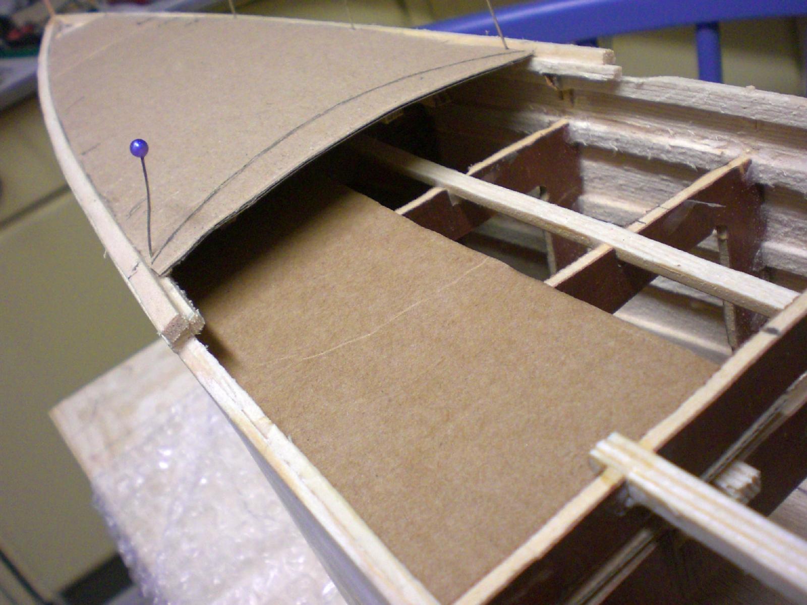
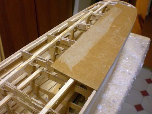
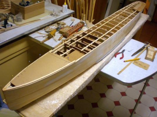
 Build log part 14 preparing for the decks, cutting out card templates, will be using 0,8 mm ply and plank this with 1 x 2mm scaled pine strips, pencil "caulking" at the plank edges Nils inbetween I do 2 more windows at a time... the forecastle card template and half the front waist template (one deck lower). The outer limiting timbers (forecastle sheer) will be shaped to fit the rounded transition from hull to deck half poop deck template

- 2,625 replies
-
- 22
-

-
- kaiser wilhelm der grosse
- passenger steamer
- (and 1 more)
-
beautiful work Igor, but I ca`nt believe that this steam schooner will go through the bottle neck , unless you are able to perform a miracle ... Nils
-
Mkmossop, I second comment and methode of Tadeusz stitch size as small as possible, and cloth-widths should be acc. to scale requirements of the epoche concerned. Using textile glue for minimal wide folding the sail edges once or twice before sewing them over is OK. If you desire best optic, sew on a bolt rope and perhaps some reinforcement patches in the sail fastening- and wear areas Nils
-
Nice build Ioannis, wish you further much fun and success with this scratch-built cutter... Nils
- 17 replies
-
- 1
-
-
- abythistos
- cutter
- (and 2 more)
-
Hi David, I use Aluminium metal foil for the plating, please have a look at the examples in my "Pamir" build log beginning there on page 4 with post #65 of that log and onward....(link in my signiture).... Nils
- 2,625 replies
-
- 2
-
-
- kaiser wilhelm der grosse
- passenger steamer
- (and 1 more)
-
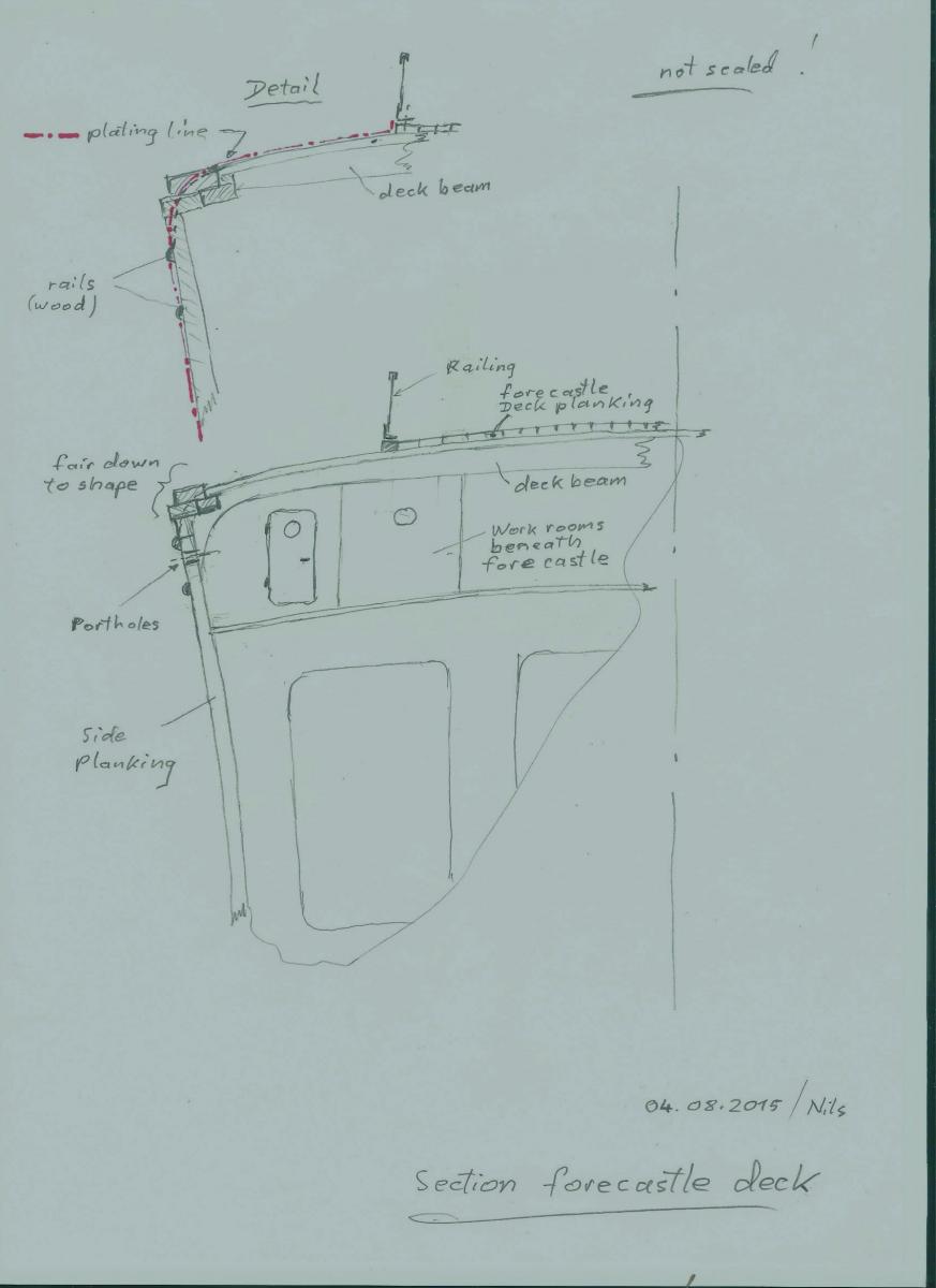
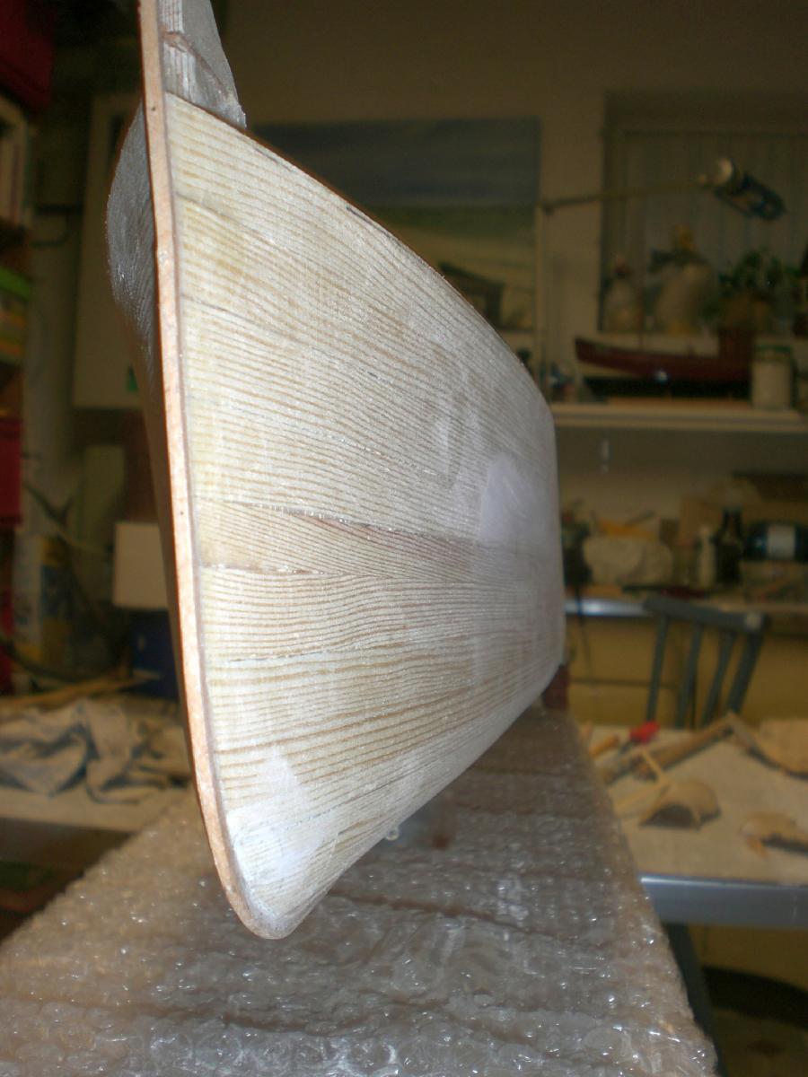
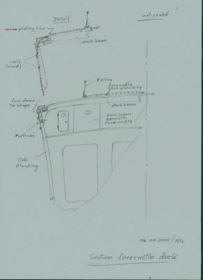
Thanks for looking in Denis and Scott, and all the "likes"... Denis, I have the wooden hull smooth and treated with filler where necessary, all is covered with one coat of nitro- Wood-bounder, to fix the grain. The forecastle deck is very much rounded down to the sides typical for this ship (like some fishing Trawlers have), that is what I`m working on right now. These rounded side Areas of the forecastle deck will be plated as well... Scott, thanks for dropping in,.... The plating of the hull still needs to wait until I have the decks on, and the upper two rails mounted to the sides Nils Ammendment : here a non scaled hand-scetch for illustration,,,,
- 2,625 replies
-
- 10
-
-
- kaiser wilhelm der grosse
- passenger steamer
- (and 1 more)
-
Very nice looking parts for masting and rigging Frank, trust you will be Setting the masts and stays in the next days... Nils
-
fantastic Job Erik, hard to believe that this is your first wooden model, Very well done ! Nils
- 222 replies
-
- 4
-
-
- 18th century longboat
- model shipways
- (and 2 more)
-
HMS Alert 1777 by Jaekon Lee - 1/64
Mirabell61 replied to Jaekon Lee's topic in - Build logs for subjects built 1751 - 1800
wunderbar, excellent modeling Lee, its one of my favorites on this Forum... Nils -
treenailing Looks really nice Nigel, Nils
-
Thanks for dropping in again Johann, and for your kind appreciation... Nils
- 2,625 replies
-
- 1
-
-
- kaiser wilhelm der grosse
- passenger steamer
- (and 1 more)
-
Nigel, thank you for your nice words....., very much appreciated, I am momentarily considering the ponce-size for the "riveting"...... my favorite Ponce structure is like I did for the "Heinrich Kayser" Steamer, but that was in scale 1:96. For scale 1:144 it might be a wee bit too large, but it would Show a clear riveted Skin structure, even when the paint is on later. Nils
- 2,625 replies
-
- 2
-
-
- kaiser wilhelm der grosse
- passenger steamer
- (and 1 more)
-
Chuck, laser cut gratings and coamings look great... Nils
- 1,051 replies
-
- 1
-
-
- cheerful
- Syren Ship Model Company
- (and 1 more)
-
thank you David,Grant and John, David, the entire hull will be me "metal-plated in riveting mode", once the decks are established Grant and John, your nice comments are much appreciated, I`m glad you like it Nils
- 2,625 replies
-
- 1
-
-
- kaiser wilhelm der grosse
- passenger steamer
- (and 1 more)
-
Thank you very much Patrick, Thats a well appreciated comment of yours.... the upper two parallel rails will be of wood, (semi-round 1 x 2mm nutwood), but before fixing these I have to get the decks in place first. That will take some time. The metal plating will be between those rails, so that they have a good contact wood to wood Nils
- 2,625 replies
-
- 1
-
-
- kaiser wilhelm der grosse
- passenger steamer
- (and 1 more)
-
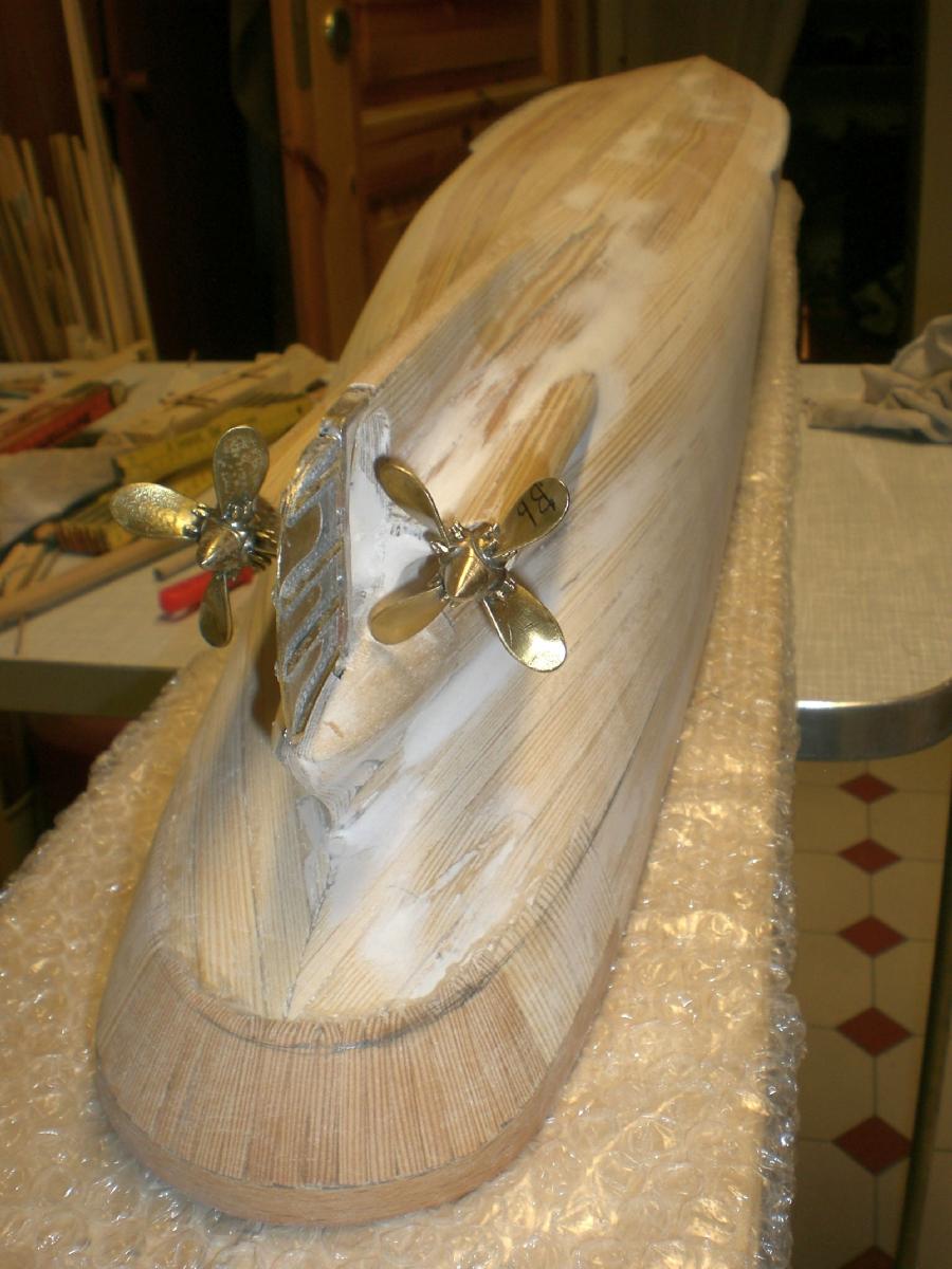
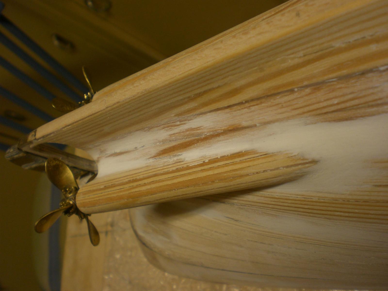
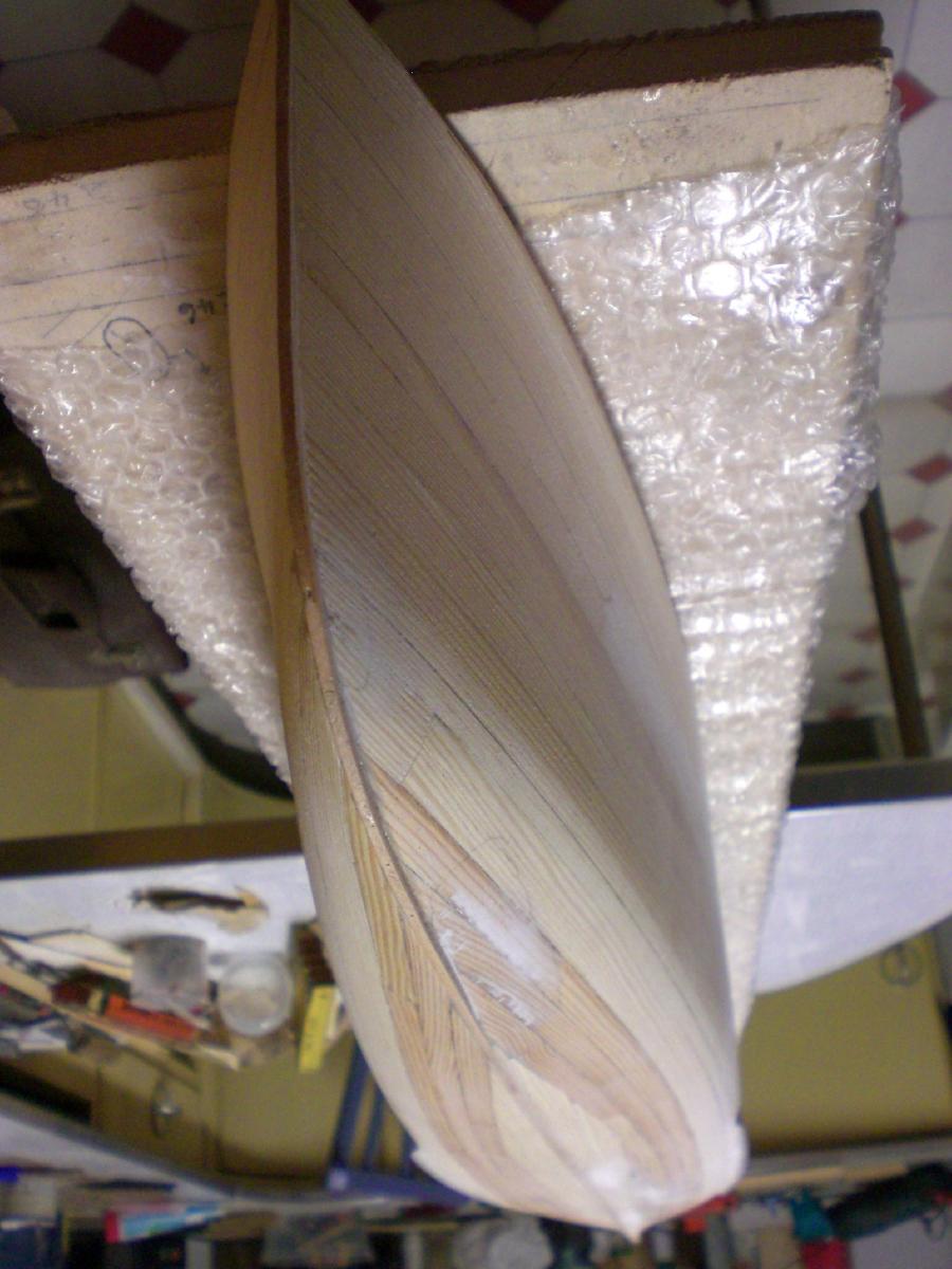
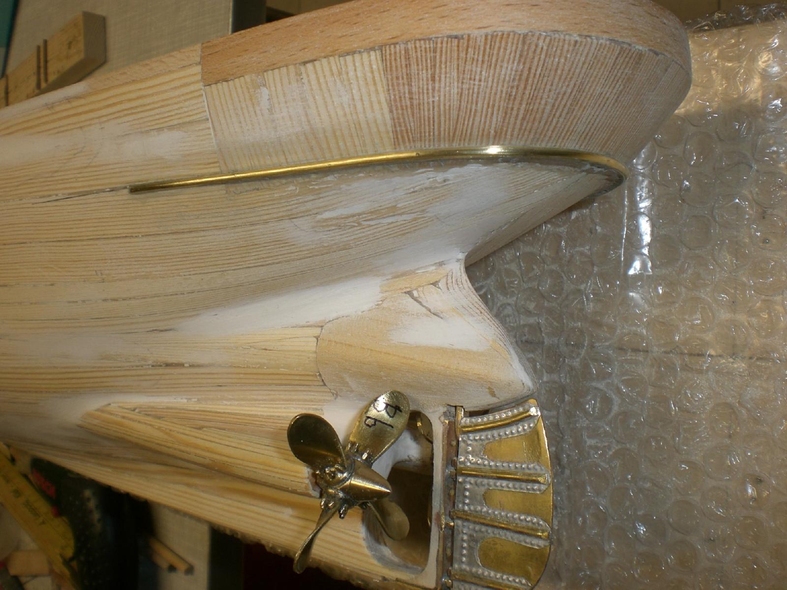
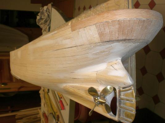
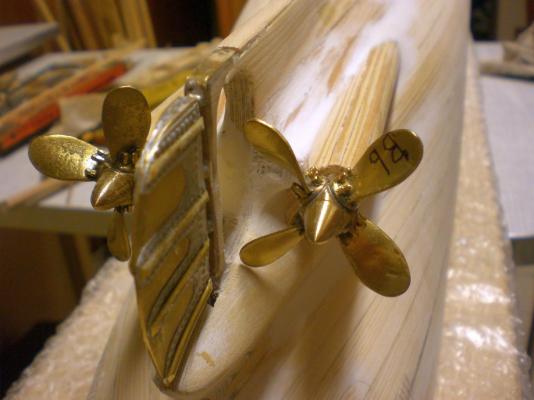
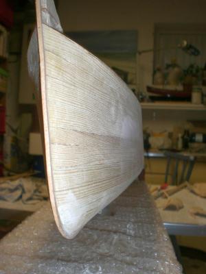
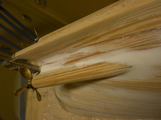
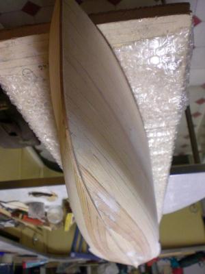
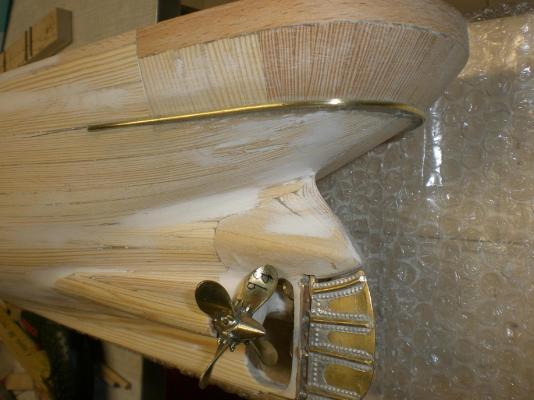
Build log part 13 a little update... applying a bit of filler for blending out transitions and putting on the transom knee-rail around the stern... Nils pencil mark for the transom rail nice smooth hull now... blending out of the propshaft housings the lines of an early "Blue Riband racer" the transom knee rail is of brass, in order to resist / avoid later dents from knocking against... Glued and fixed to the hull with 15 brass anchors 0,6 mm diam.

- 2,625 replies
-
- 25
-
-
- kaiser wilhelm der grosse
- passenger steamer
- (and 1 more)
-
beautiful work Ed, cutting and shaping rasping and fairing the filled out Frames, the reward is a great looking hull with beautiful lines.... Nils
- 191 replies
-
- 5
-
-
- young america
- clipper
- (and 1 more)
-
Talos, agree, that would be a terriffic sight, seeing all those sisters during a "Operation Sail" event or so...... The Gorch Fock II threemast barque though is a post war build, launched 1958 at Blohm & Voss shipyard Hamburg, and allthough since then many updates, changes and more safety related modernizing and fitting out have taken place, it`s momentary condition can be considered as one of the safest and well mantained ships of the german Bundesmarine. The first Gorch Fock 1, (intermediate Russian named : Towarisch) being one of the original 6 sister ships as you described , to my knowledge is moored to the pier in Stralsund (Baltic sea) waiting to be re-rigged and overhauled, provided there will be sufficient financial sponsoring. Nils
-
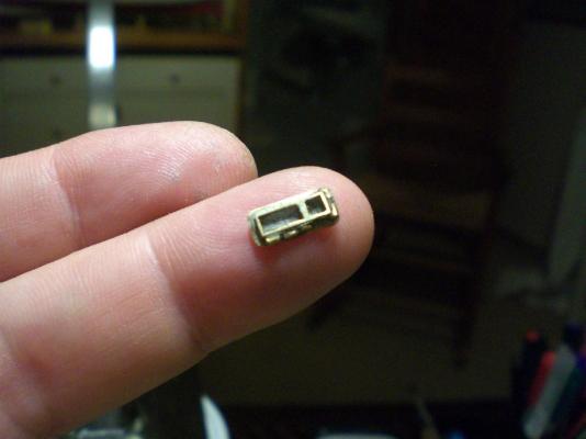
thank you very much Bob, John and Martin, ....and the " likes " for your nice comments on the prototype window, ist about smallest I can make this way with my limited capability, wish I knew how etching works, but thats more for modeling professionals... I`m also thinking of the making of the only 8mm high outer deck railings. They require vertical 4 "wires" in horizontal direction as well as an (if possible) wooden handrail on top. Finaly, per Web Research, as semi material, I have found some 8mm high photo etched 6-chord material in scale 1:150 that suits well the requirements from the geometric side, I`ll do a sample and hope it shall work out well Nils
- 2,625 replies
-
- 5
-
-
- kaiser wilhelm der grosse
- passenger steamer
- (and 1 more)
-
Thanks for explaining Dan, I was so amazed of your speed of building,...., now I understand. Nevertheless a great model and the scale 1:192 is a very ambitious one to tackle, well done ! Nils
- 108 replies
-
- 3
-
-
- andrea doria
- ocean liner
- (and 1 more)
-
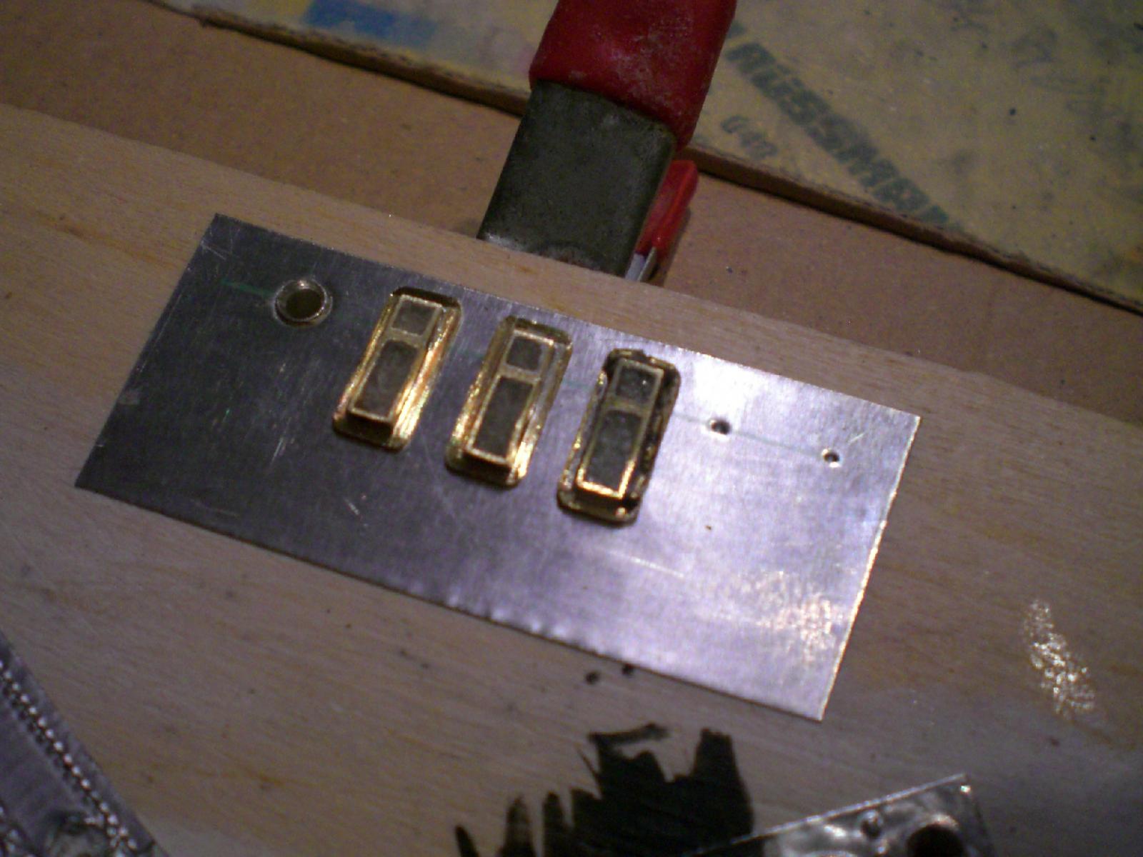
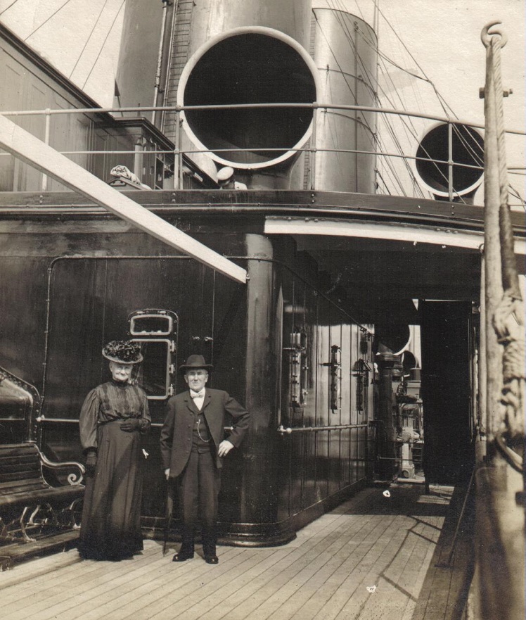
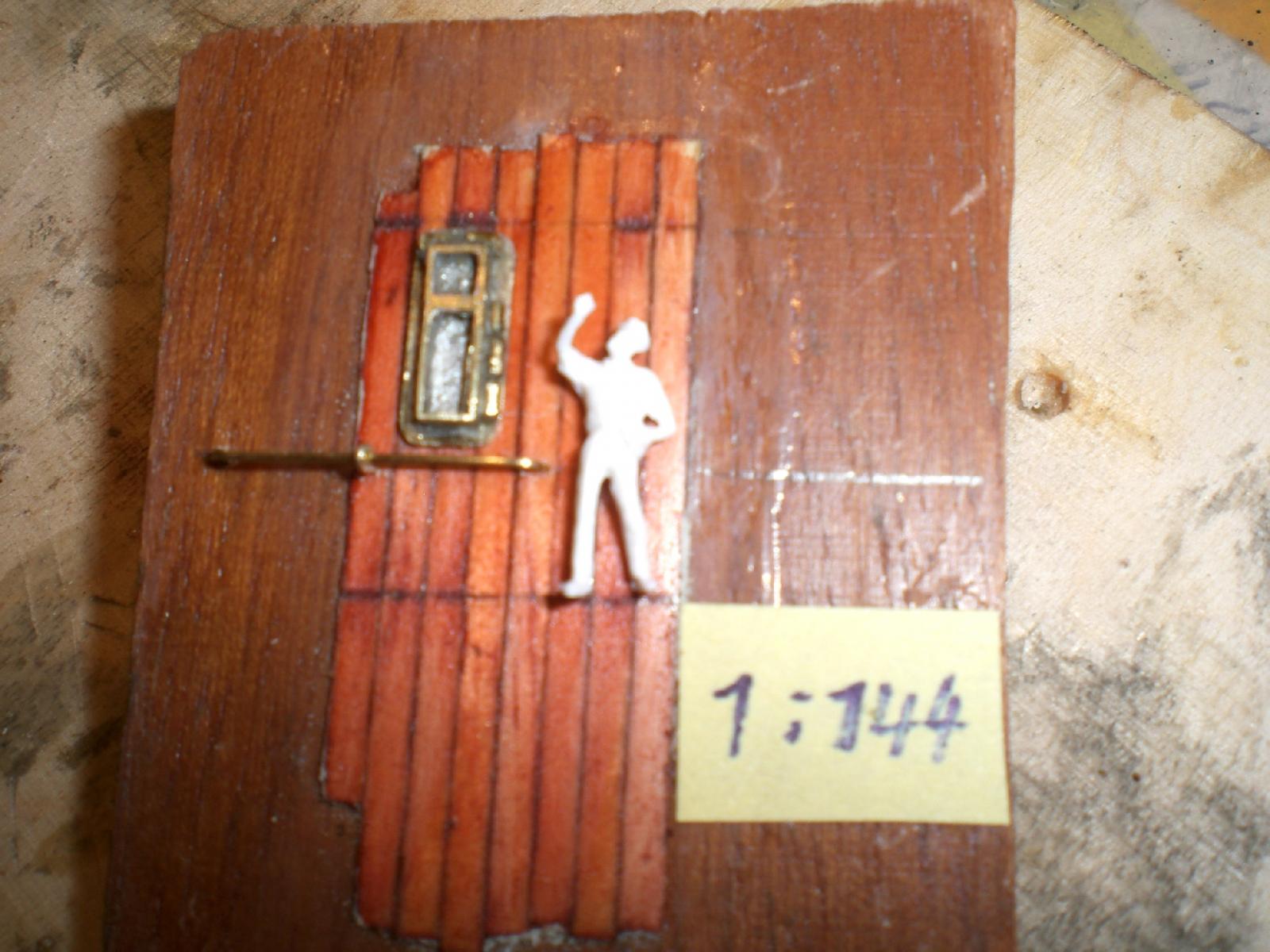
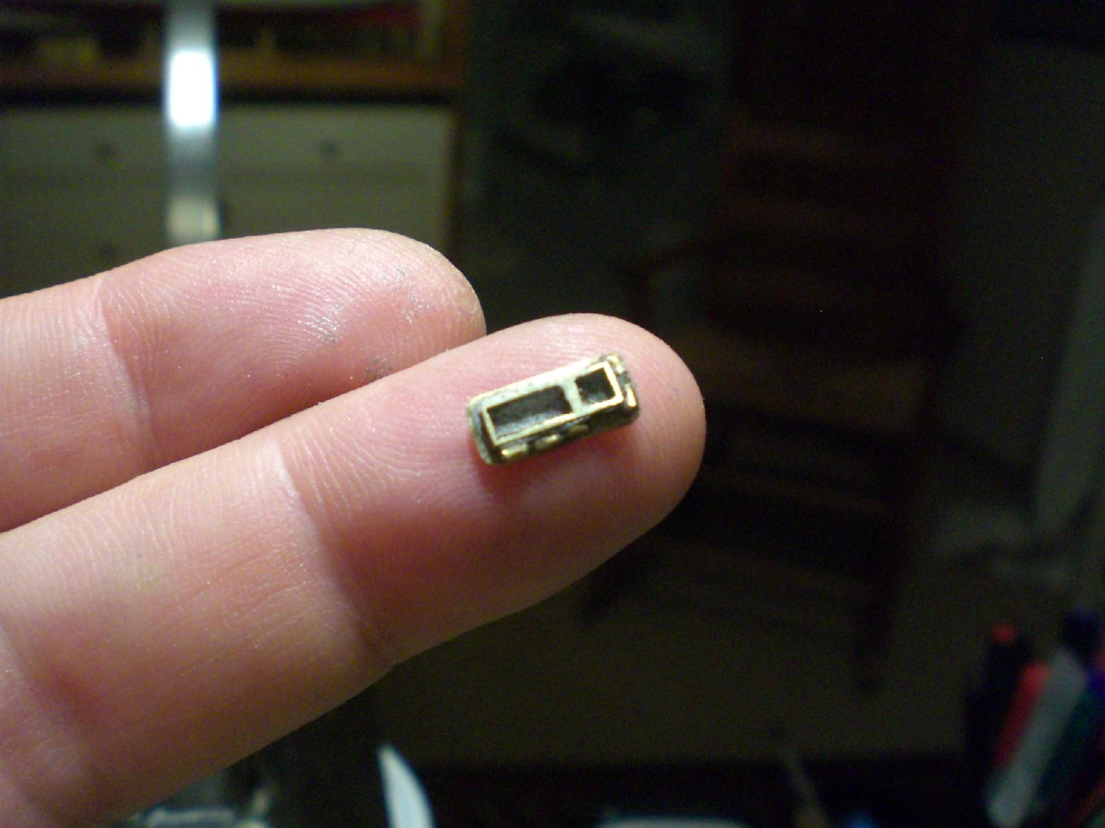
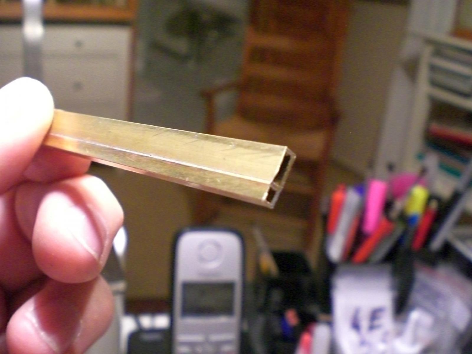
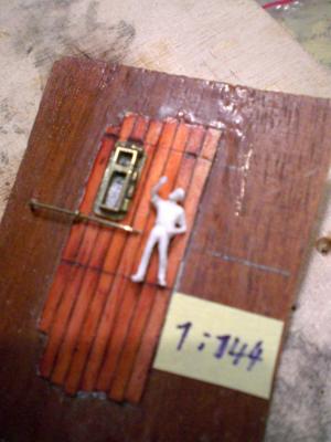
update.... some trials for promenade-deck / boat-deck windows..... This one of the pics that Peter (Mr. Hollom) sent me with the old couple in front of the deckhouse with the windows concerned, inspired me at least to try do it in scale 1:144 and in brass. This is the result of the first trial (yet without glassing)..., before the glassing comes in, the background of the "pans" are painted silver-grey, for glassing I intend to place resin into the frame, that cures without shrinking and remains completely transparent in the frames The window is a vertical doubleframe with common mounting flange and 3 hinges sidewise for the larger frame and 2 hinges on top of the smaller frame. Its completely made of brass, if I could, and had the capability, I would have etched it out of plate.... The reason for doing this trial now, is because there may come some ideas for improvements for better looking, and when the lot is made, there will be round about 80 - 100 windows to make in repeatable mode Nils double-frame window type common frames are made from hollow brass square rod resp. rectangular rod, I soldered both together and cut slices.... soldered onto a common plate (mounting flange) and glued the hinges on (three sidewise , two at the top) the two horizontal pencil-lines resemble the deck levels on the little mock up sample and the handrail is directly under the window the model figurerine is only 12 mm high


- 2,625 replies
-
- 25
-
-
- kaiser wilhelm der grosse
- passenger steamer
- (and 1 more)
-
nice and fast work Dan, did you cut off the hollow eyelets or drill deep enough into the wooden hull to take them up ? Nils
- 108 replies
-
- 1
-
-
- andrea doria
- ocean liner
- (and 1 more)
-
Hi Patrick, maybe something like this will do...... http://www.amazon.de/Millionen-Endoskop-Kamerakopf-Einstellbare-Inspektionskamera/dp/B00W6M26O8/ref=sr_1_4?s=books&ie=UTF8&qid=1438186339&sr=8-4&keywords=digital+endoskop+kamera saw them by Amazon, also Ebay, round about 25 - 35 Euros Nils