Mirabell61
-
Posts
7,418 -
Joined
-
Last visited
Content Type
Profiles
Forums
Gallery
Events
Everything posted by Mirabell61
-
 Tony, thanks for sharing your find..... Nils
 -
Thanks for your nice complement Lee, Nils
-
Thank you very much Popeye, Nils
-
Johann, simply wunderbar ! your "La Creole" in all her parts and Details... Nils
-
Very nice build David, Nils
-
wishing you just as much fun and joy with this smaller Version Ed, would love to see it under way soon... Nils
- 191 replies
-
- 1
-

-
- young america
- clipper
- (and 1 more)
-
wonderful work Patrick, accurate and precise execution, must be extreme lightweight construction... Nils
-
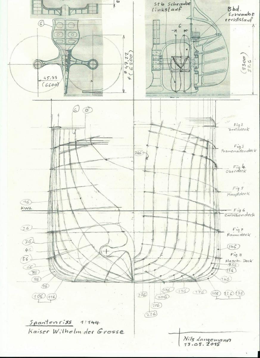
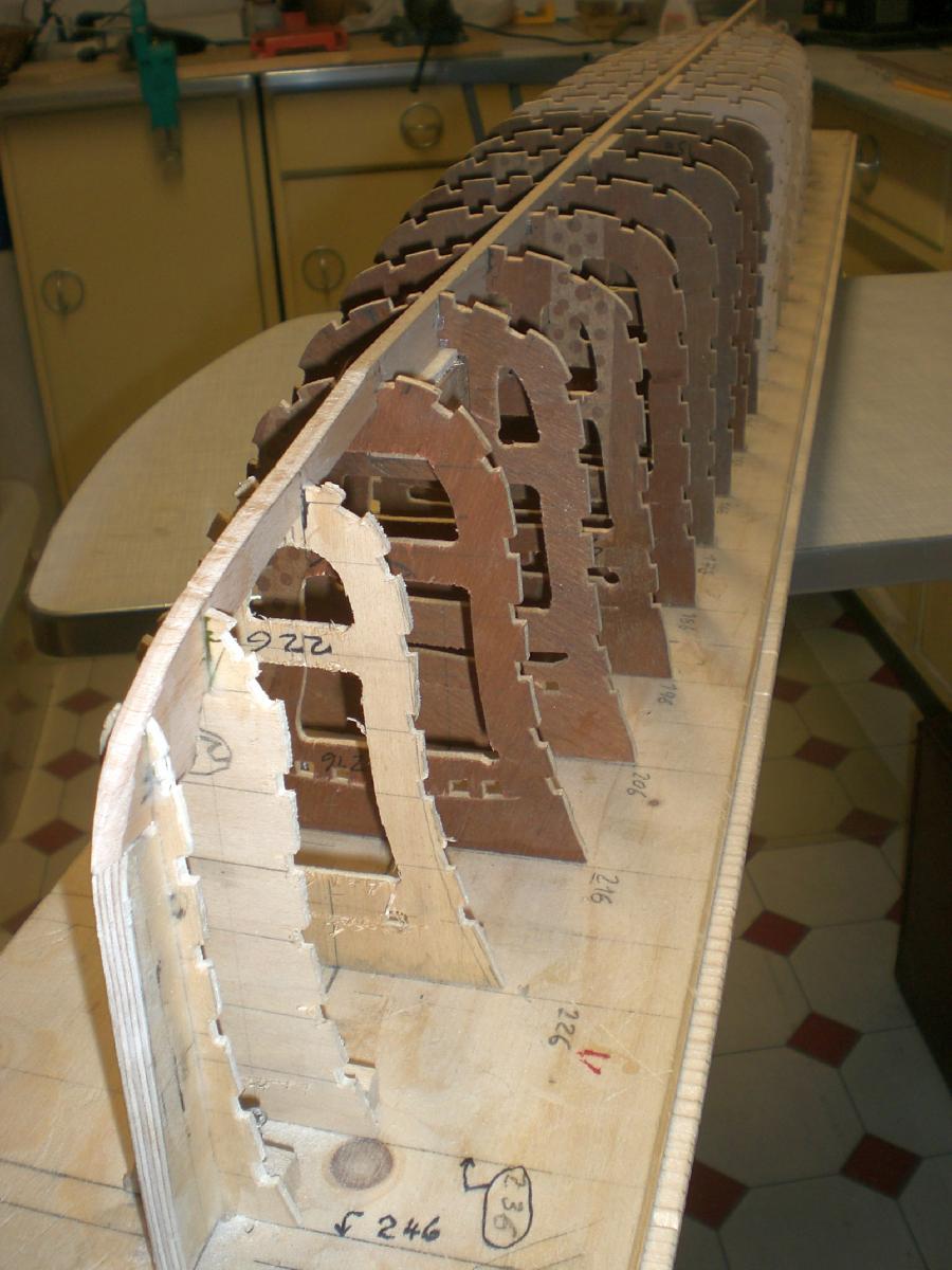
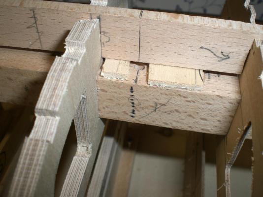
Many thanks to my fellow building mates Mark - Patrick - Robin - Ben- David, and all the "likes" Mark, I`m happy that you like and enjoy following the progress... Patrick, whilst doing the hull I can well imagine, what the actual designers had in mind way back in 1897 Robin thanks very much. I do hope that the original shaped ship`s magnified shape and lines can be brought into this model, I also love the shape of this early engineering and shipwright design Ben, I appreciate your nice comment, and hope you shall further enjoy...... David, I`m glad you like it. For determining the stringer notches I refer my own drawn frame plan. I`ve set a stringer at the outside frame contour at the crossing point of every horizontal deckline (see pic below) Nils how to determine stringer notches..... The bilge keels will be brought in later on...

- 2,625 replies
-
- 17
-
-
- kaiser wilhelm der grosse
- passenger steamer
- (and 1 more)
-
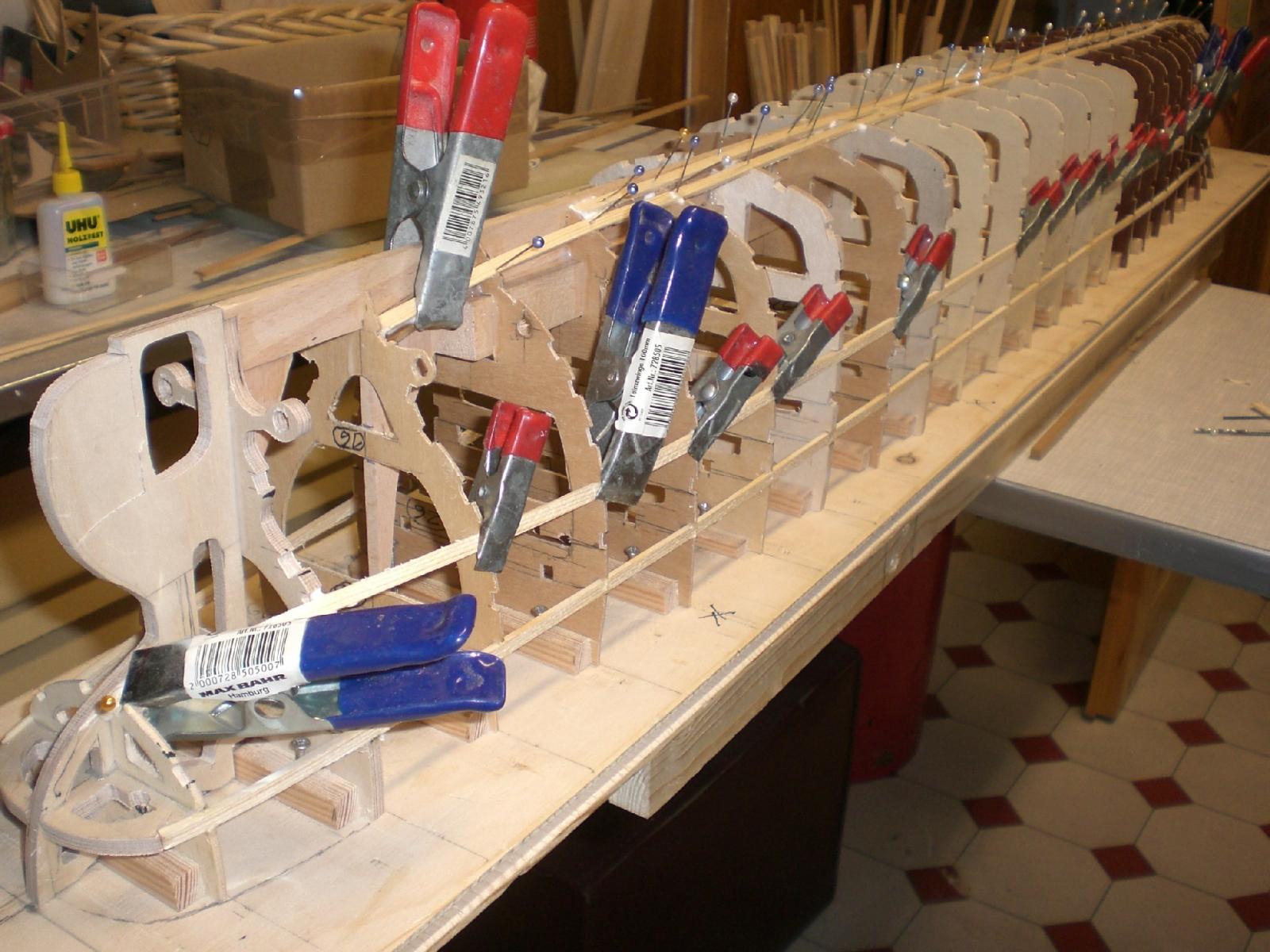
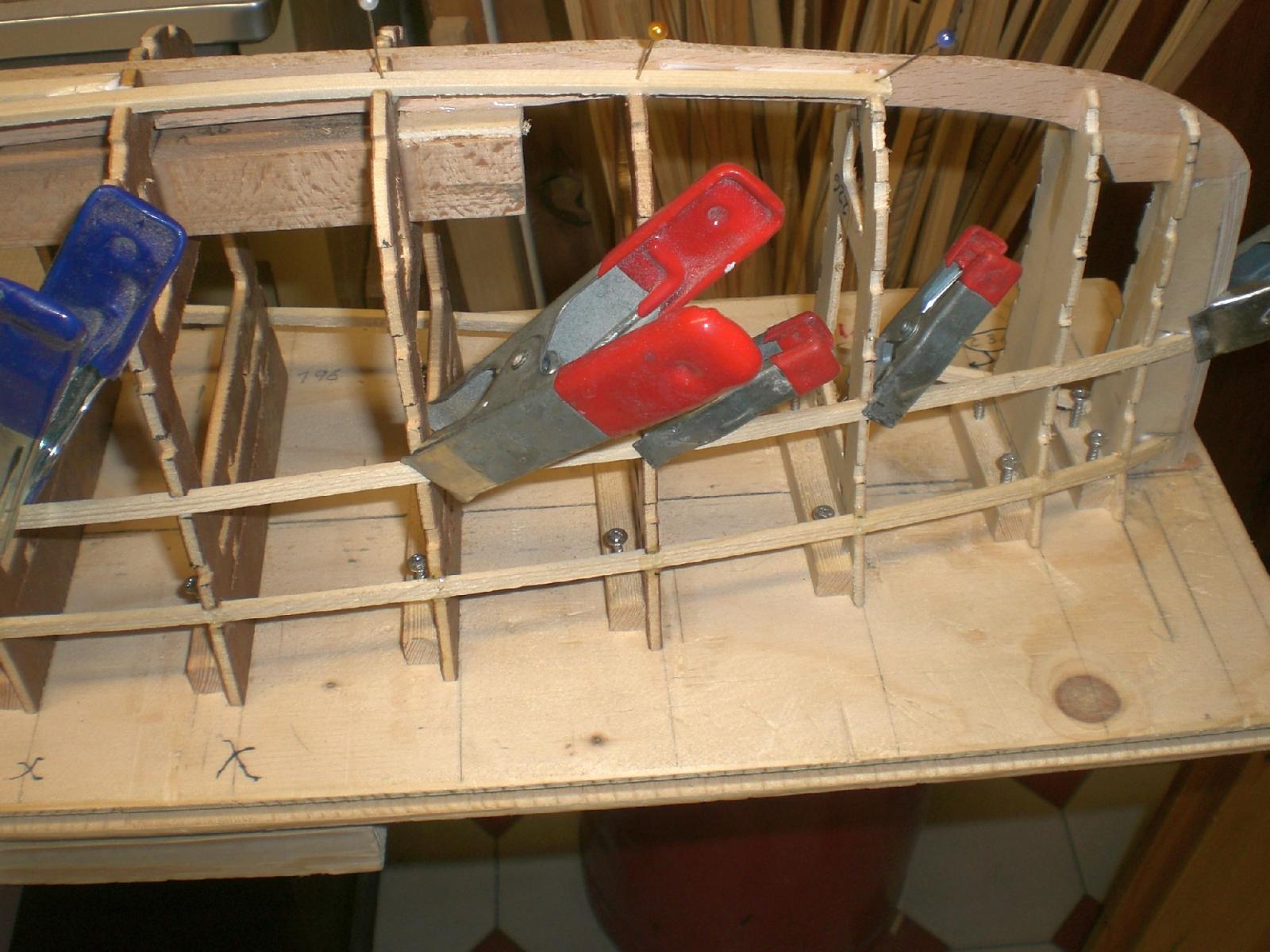
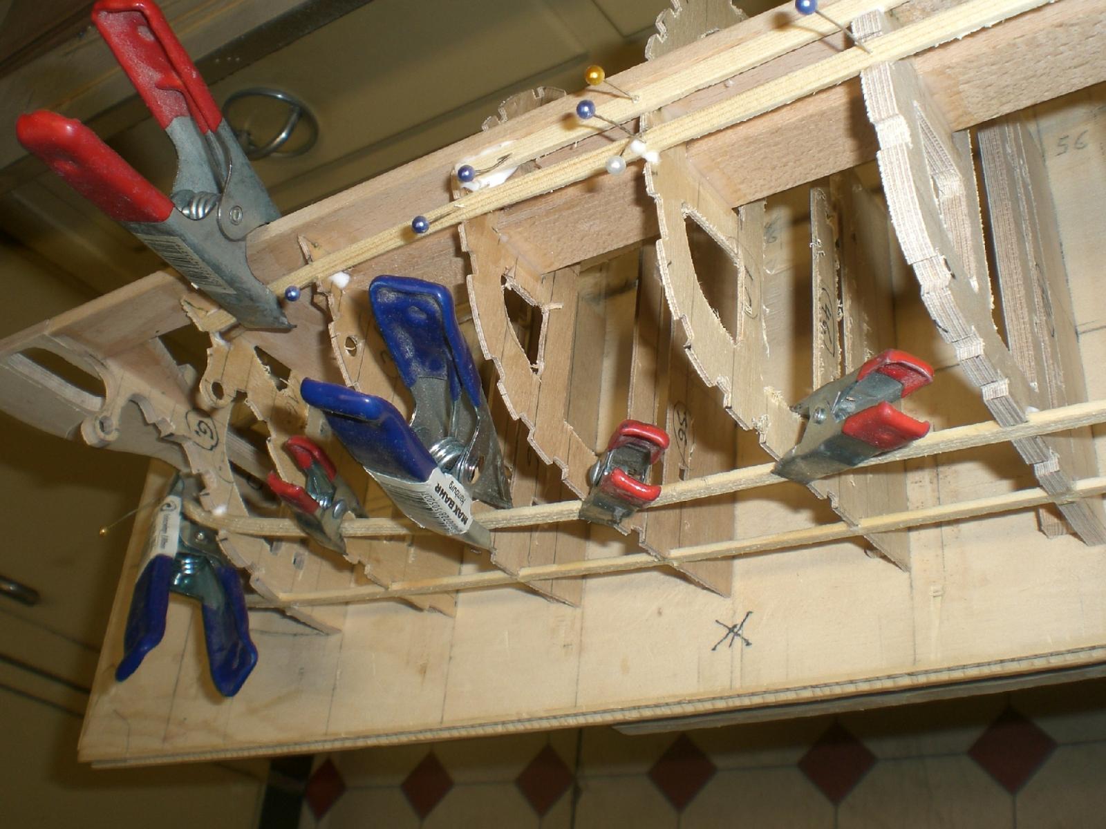
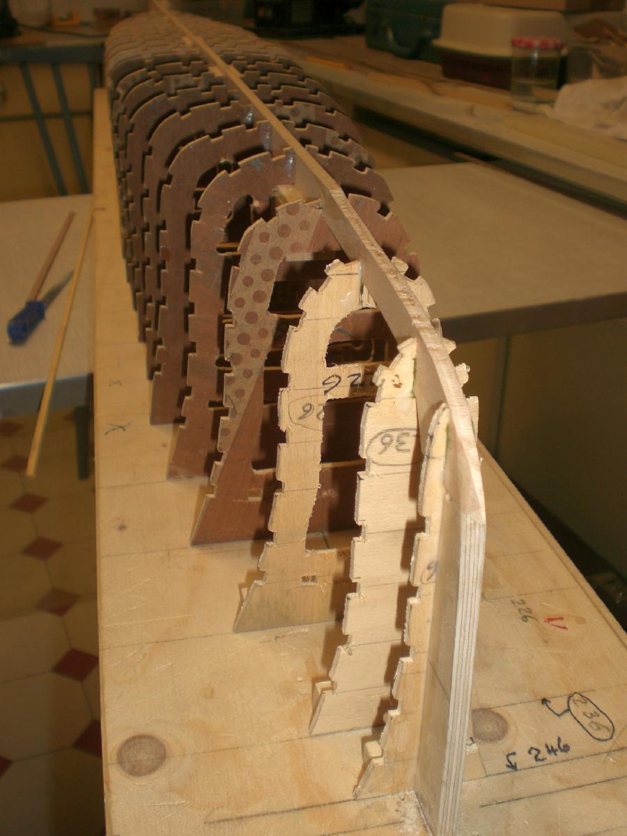
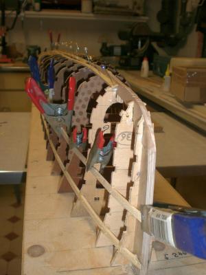
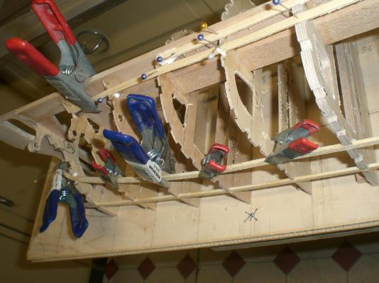
Starting with the stringers....... it takes appr. 2-3 hours to have the glue cured, before removing the pins and the pegs for the next glueing session I`ll have to move the screws that hold the frames more to the outside for having better access to the srews now, before further stringers are put on the relatively long and gentle bows do not bring too much tension on the on the wooden strips the tricky part of the job though will be the stern portion, maybe I shall use filler pieces to a certain degree.... Nils


- 2,625 replies
-
- 28
-
-
- kaiser wilhelm der grosse
- passenger steamer
- (and 1 more)
-
Many thanks Nenad and Dafi, and all the "Likes"..... Nenad, thats a nice comment , also wish you all the Magic on your CS, I saw you (like it..) are making so many Details by yourself Dafi, Thanks Dafi, glad you like it, and greetings from Glinde to Ludwigsburg Nils
-
Thanks very much Pete, Nils
- 2,625 replies
-
- 1
-
-
- kaiser wilhelm der grosse
- passenger steamer
- (and 1 more)
-
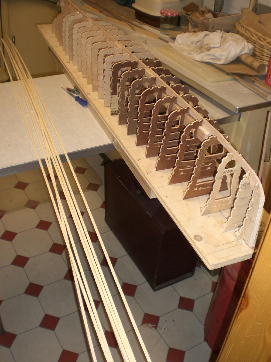
Thanks Popeye, my other ship hulls are also built comprising stringers of pine wood. If the stringers follow the frame outer contours without dents and boils, the planking afterwards shall be an easy job to do. Also the stringers provide very useful hold for glueing and for for all the pegs and pins whilst planking. It is also much easier to do the sanding over the stringers and same time in some places the slightly overstanding odd-outer frame potions when fairing (before planking) I do single layer planking, 2mm thick and use mostly only white PA glue. I do`nt use screws or nails for planking Nils
- 2,625 replies
-
- 6
-
-
- kaiser wilhelm der grosse
- passenger steamer
- (and 1 more)
-
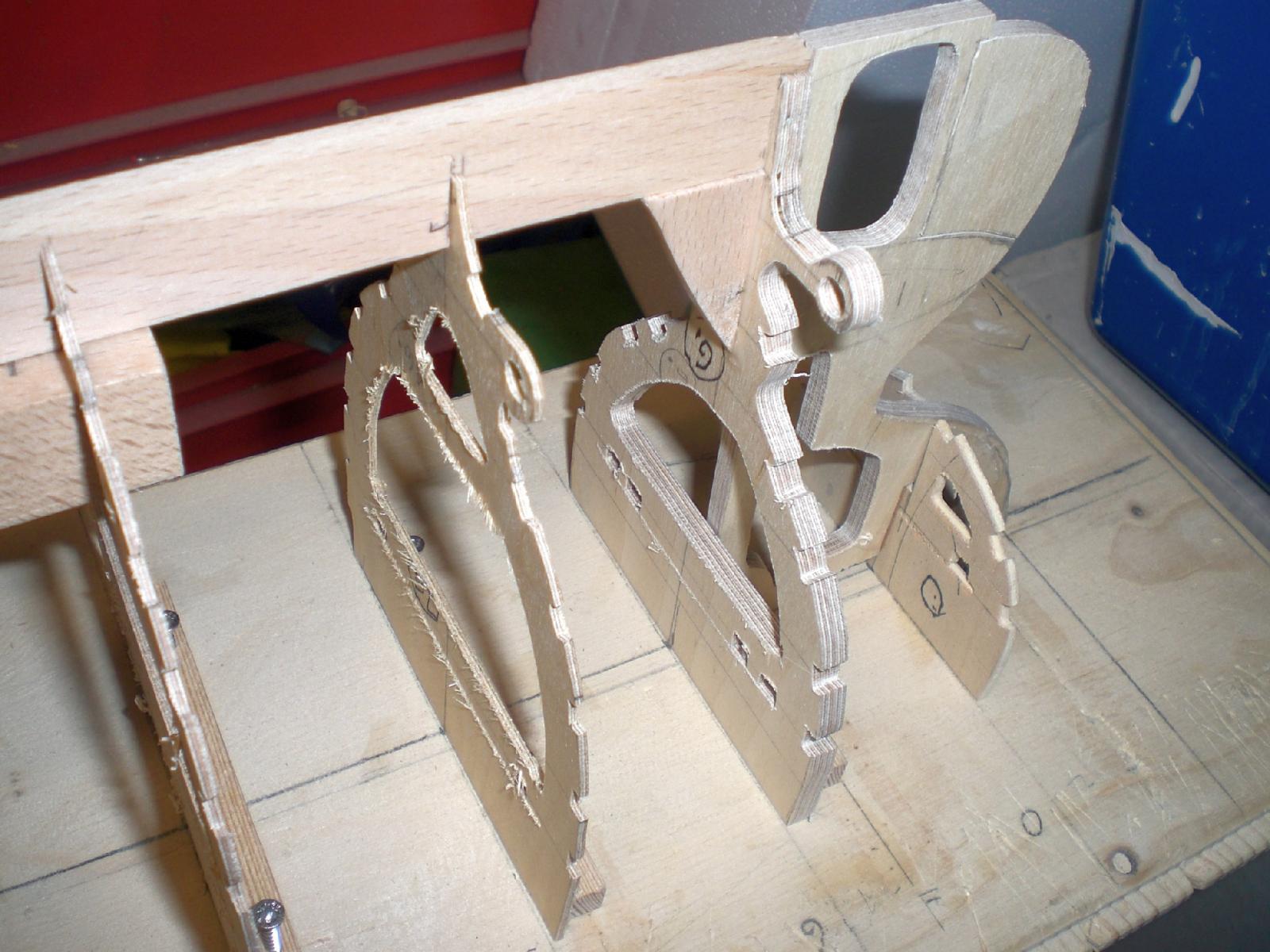
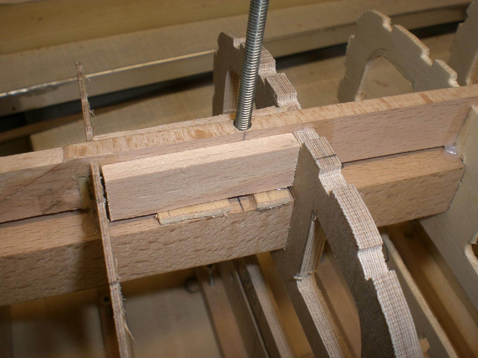
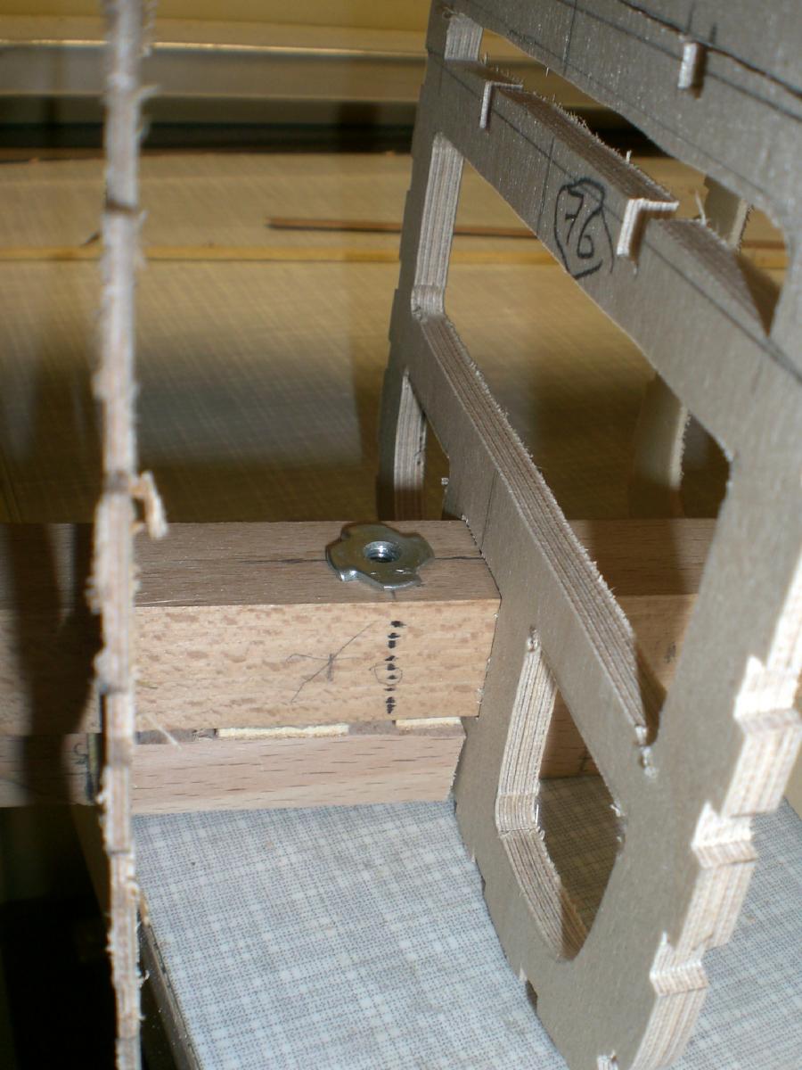
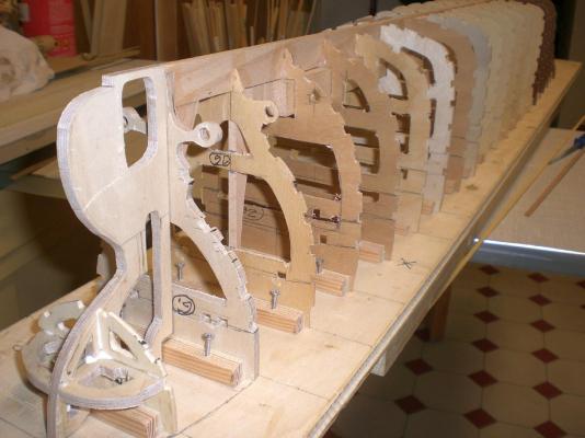
Build log part 5 preparing for attaching the stingers to the frames all frames are set and glued in. The cut out notches for the stringers are also done there are three places, where the 3 stand M4 spindles go through keel and square bar. Some supporting ply bits prevent later distortion of keel when spindles are tightened to the stand spindle fitted in and reinforcement cladding both sides to the keel there are locking nuts M4 on the inside of ship (into the sqare bar) bow post fitted in and beveled to angle where the later planking will lay on Stern is also prepared for putting on stringers the stringers have been cut with my hand- circular saw, (which I fitted as a table-saw) Then cut the 2 m long strips from a 5 mm thick plank. I wanted to have the stringers over the full ship length in one piece Nils


- 2,625 replies
-
- 26
-
-
- kaiser wilhelm der grosse
- passenger steamer
- (and 1 more)
-
beautiful schooner hull Gary, I like also the nice Color giving.... Nils
-
Beautiful work Pete, you have already so much practise in building These small boats, I trust you could do the hull over the Weekend if necessary. To date you must have quite an extensive number of craft moored to you model Floating marina Very well done ! Nils
- 77 replies
-
- 2
-
-
- alerion
- herreshoff
- (and 1 more)
-
beautiful work on your "Druid" section Mark, clean and precise Nils
- 172 replies
-
- 1
-
-
- druid
- sloop of war
- (and 2 more)
-
Good work Popeye, I like the Color of the deck and the Fitting out Looks very well... Nils
-
Bob, in your last post with pics the Sloop Looks great. also the metal work on it. Are you going to fit sails as well ? Nils
-
Good Progress Peter, "Pickle" is well coming on and great looking..... Nils
-
Hartmut and John, thank you very much for your Kind words and your interest in this build... Nils
- 2,625 replies
-
- 1
-
-
- kaiser wilhelm der grosse
- passenger steamer
- (and 1 more)
-
Thank you very much Bob and Mr. Pucko, and all the "likes", Bob, I was also very much interested in building a British Naval Cutter of 1777, but then favoured this odltimer Atlantic runner which was also on my list as the next Project. AnywayI have saved up all my gathered cutter-Information and plans though, perhaps for the overnext... Mr. Pucko, Thanks for your Kind appreciation Nils
- 2,625 replies
-
- 1
-
-
- kaiser wilhelm der grosse
- passenger steamer
- (and 1 more)
-
Thanks for dropping in Nigel, and thanks for your nice appreciation its good to hear from you again, hope all is well on your side (job and house moving related....) Nils
- 2,625 replies
-
- 1
-
-
- kaiser wilhelm der grosse
- passenger steamer
- (and 1 more)
-
thank you for your nice complement Popeye, very much appreciated.. The size was limited to max. 1500 mm, looks like it will turn out appr. 1390 to 1400 mm over all, but still considered as scale 1:144, but its going to be a "beast" compared with my other models. Nils
- 2,625 replies
-
- 6
-
-
- kaiser wilhelm der grosse
- passenger steamer
- (and 1 more)
-
yes Sal, and I think its just this "trying out"......that after all provides the fun... Nils
- 659 replies
-
- 3
-
-
- syren
- model shipways
- (and 1 more)