Mirabell61
-
Posts
7,410 -
Joined
-
Last visited
Content Type
Profiles
Forums
Gallery
Events
Everything posted by Mirabell61
-
 Very nice build Al, Super quality, it looks fabulous What about rigging and sails ? Nils
 -
Dirk, Thank you very much for posting this link, the pics are only for members though, I saw the fantastic model by a member, (Victory 78 ), of a different German forum, in the preparation phase, before I started mine, and at latest then, was amoung other reasons totally encouraged to build this boatstype myself.... Nils
-
Hi Jason, I`m delighted to study your well built HMS Diana and enjoyed your progress to date, keep it going... also very nice pics... Nils
-
Hi Denis, thank you so much for your appreciative words, I`m very pleased that you like it... The credit for the hatches ( for bilge access) goes to Wefalck , he gave the idea to do them at all, I did the how to do.... Nils
-
Thank you very much Geert, is your gaff day boat sailor also going to be clinkered ? Nils
-
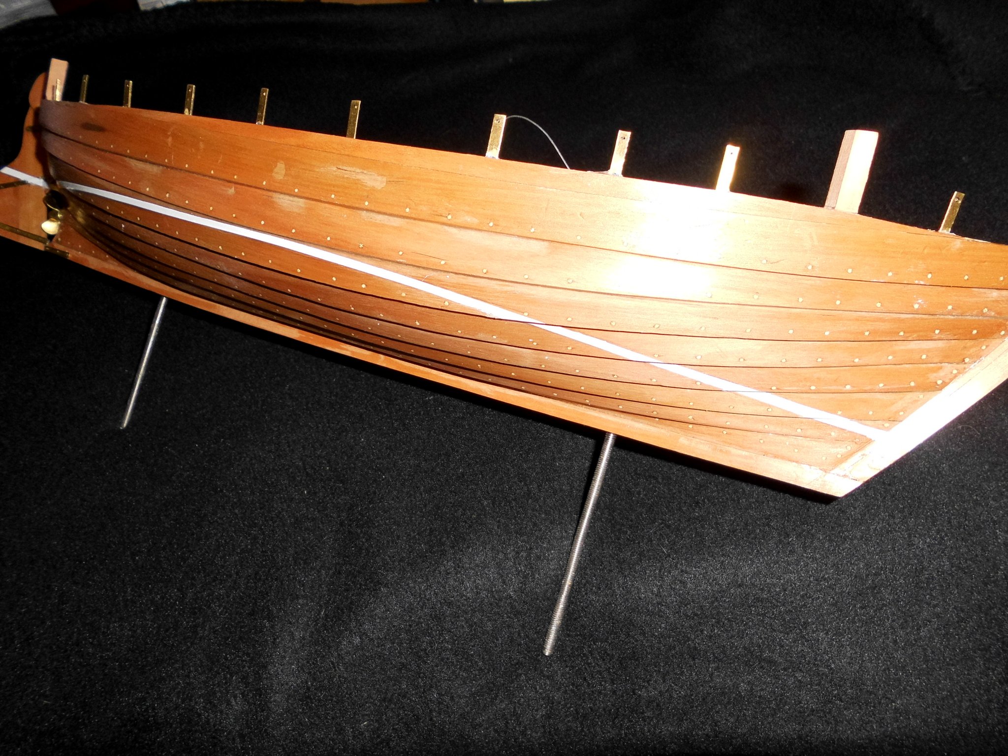
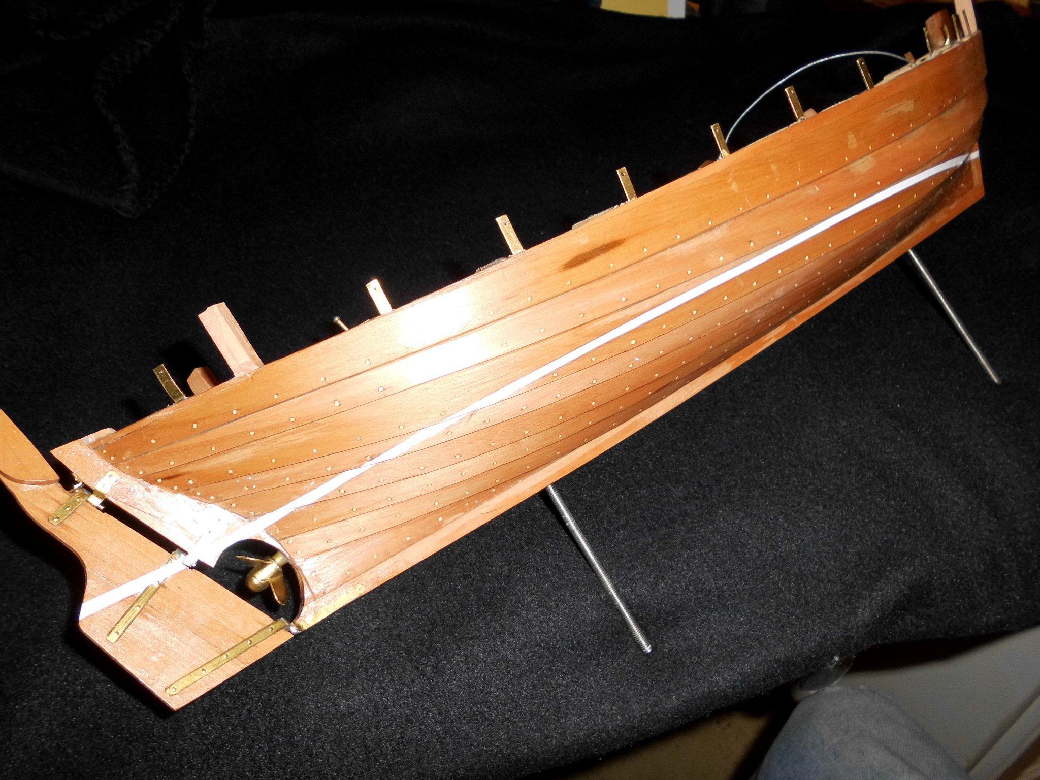
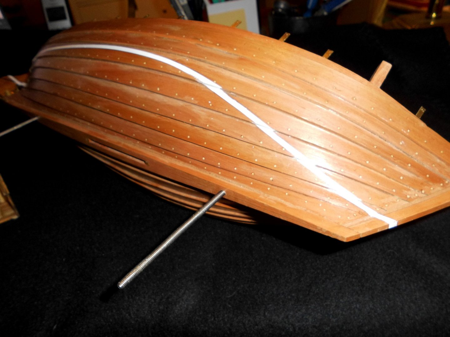
Status : I started my luck in painting the white waterline stripe. I know its a tricky task on the clinkered Hull, whos done it before will know what I mean. If viewing from horizontal waterline level the stripe will be straight, if at an angle the white paint line on the strakes will be more or less a bit "zick zack" on the steps. Next will be to mask off the white line with Tamiya tape and get the underwater red or green coat (resembling the antiouling) Nils


- 401 replies
-
- 21
-

-
Wonderful work Eberhard ! so many busy people at the winterly pier, a beautiful 19th century atmosphere, well done project Nils
-
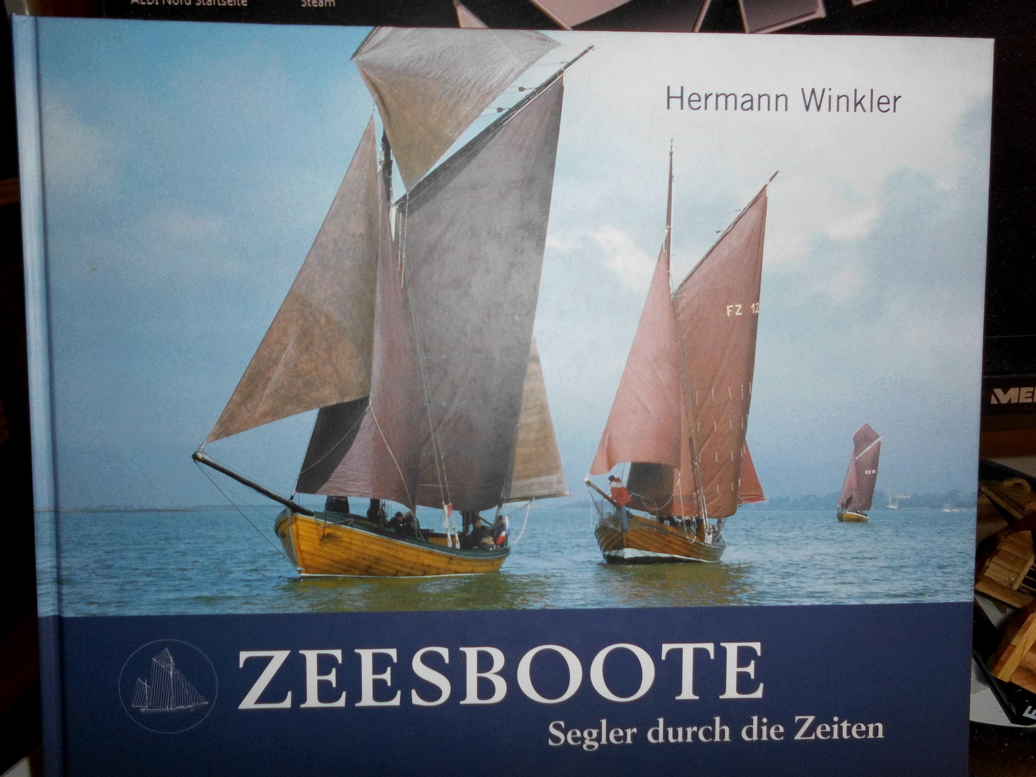
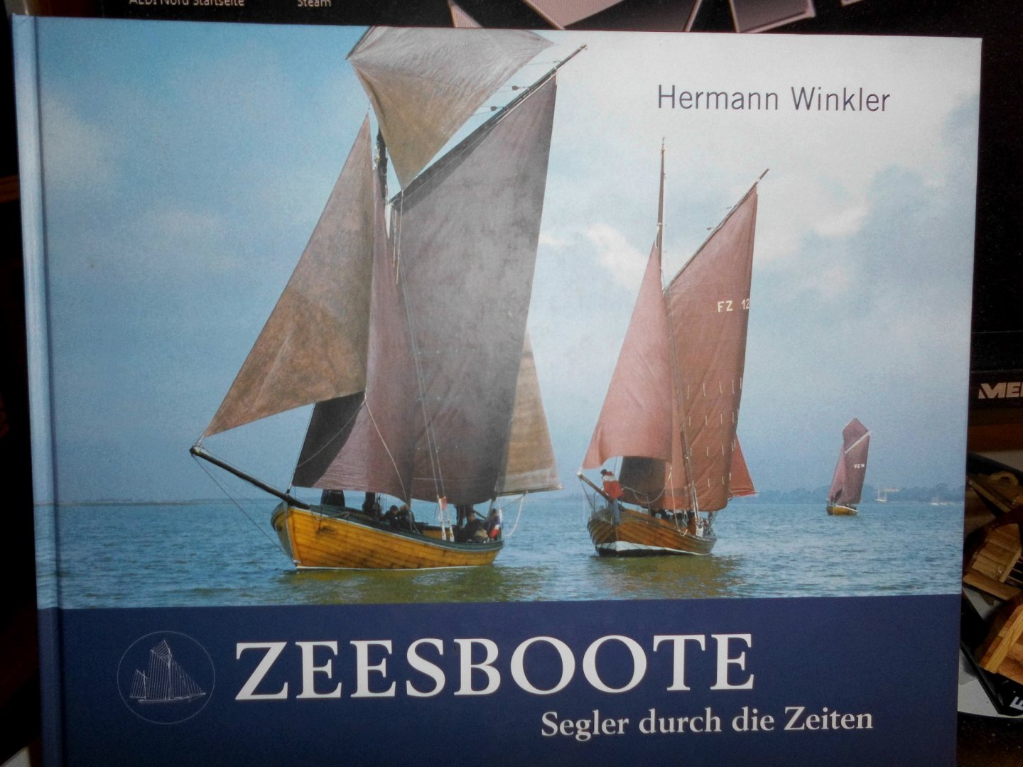
Good morning Pete, the "drawings" I used are : (please ref to my post #208) from the book Herman Winkler on page 53 and the drawing from the web, beneath the forstanding drawing, (my post #208) lines and frame plan are taken from Hermann Winklers book, page 53, of course there are quite a lot of details to be done in typical scratch build mode, but if you wish you would have my build log for comparism, or whatever you feel is worth adopting from the web`s free information..... For example I wanted the fish containments, the engine, the berths, the swivible centerboard, the engine cover, a minimum of furniture in the cabin, the oven, the ballast stones, the bilge pump, 2 scaled crew figures, the faked hatch covers to the bilge area, the horizontal plank connectors, ...etc...., and whatever is still to come... For rigging and sails later on there is enough information on the web and in the books mentioned above. I do`nt know what plan Mathias is using, guess he mentioned it somewhere, it must be very detailed, and I also did`nt find the source, but it is not needed.... Nils
-
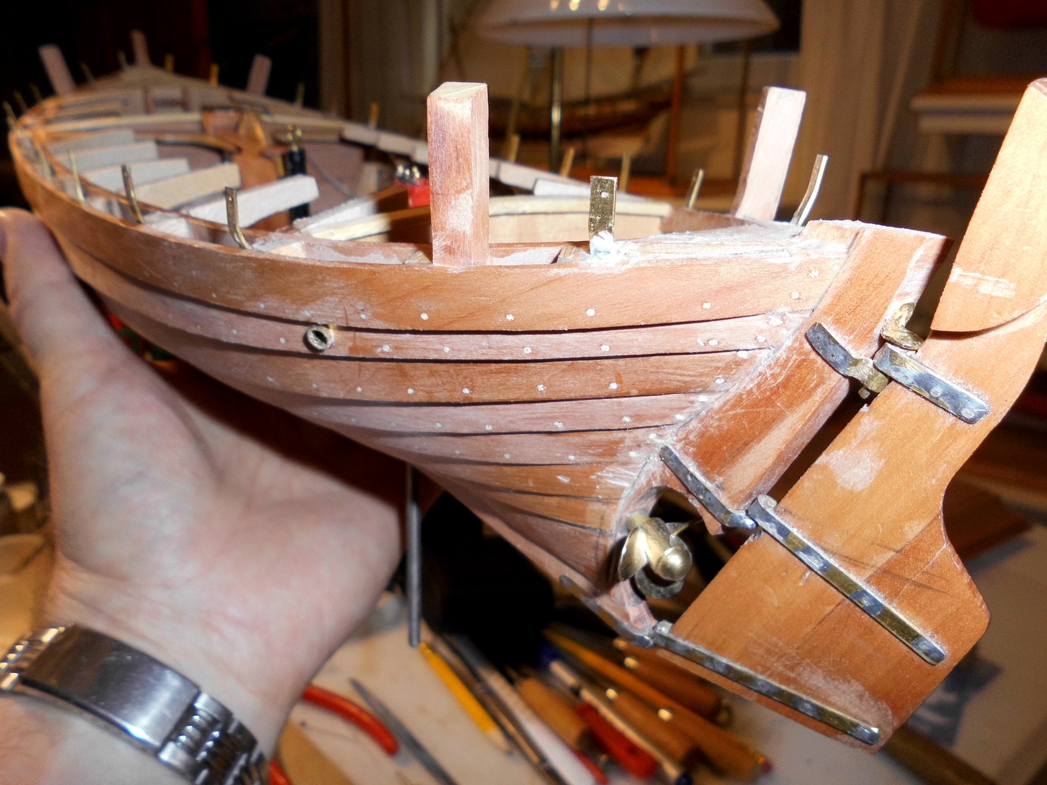
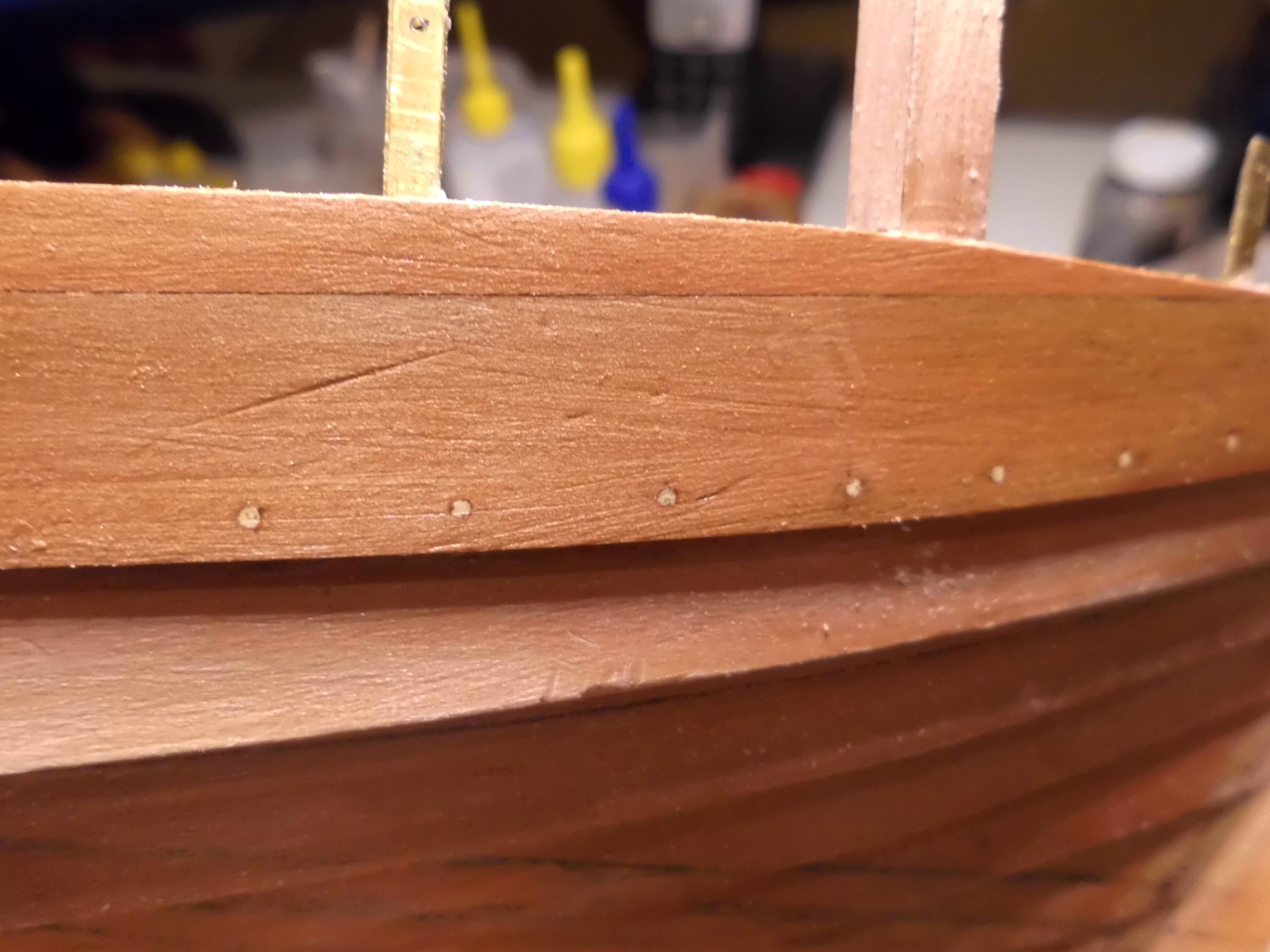
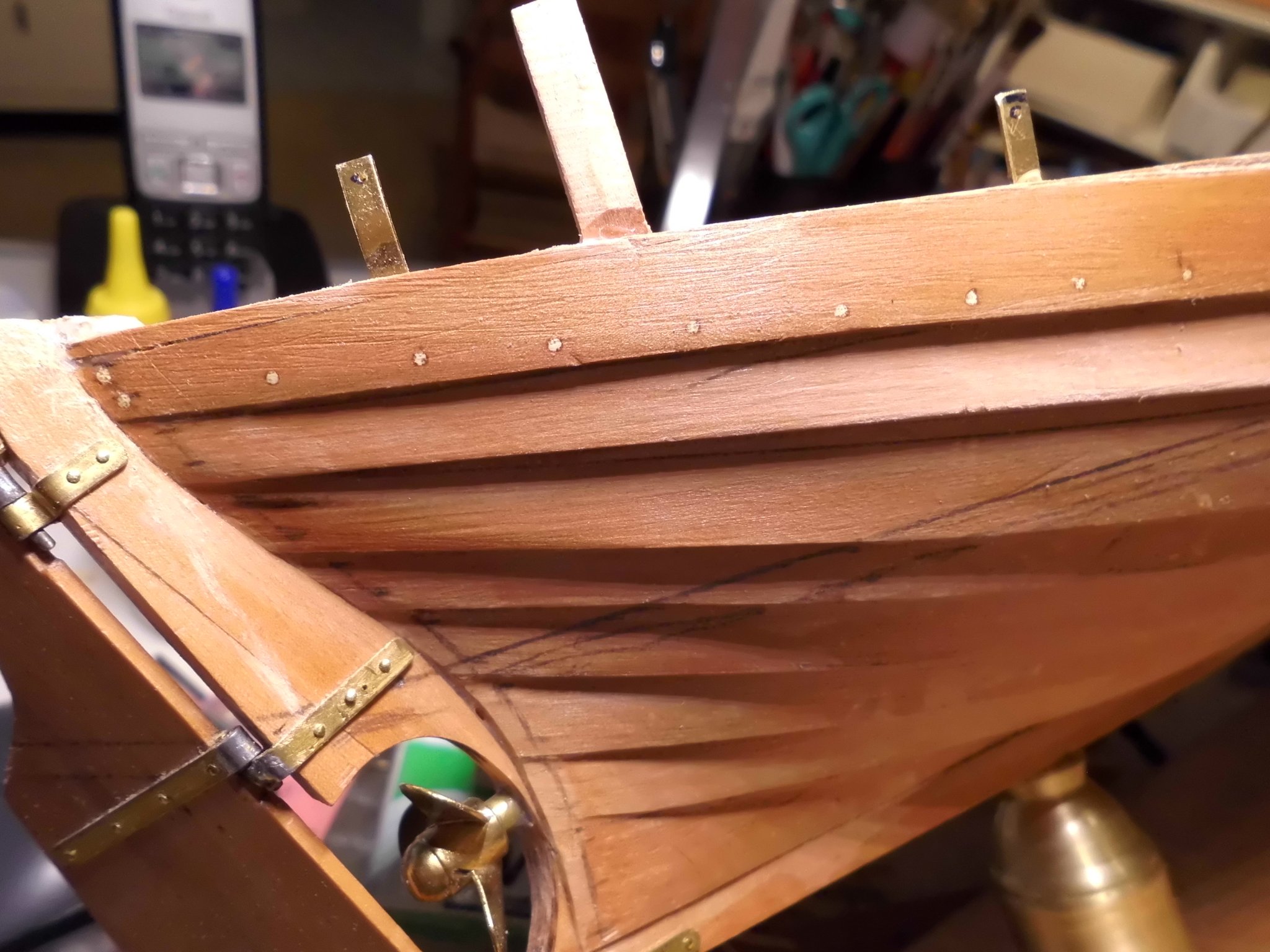
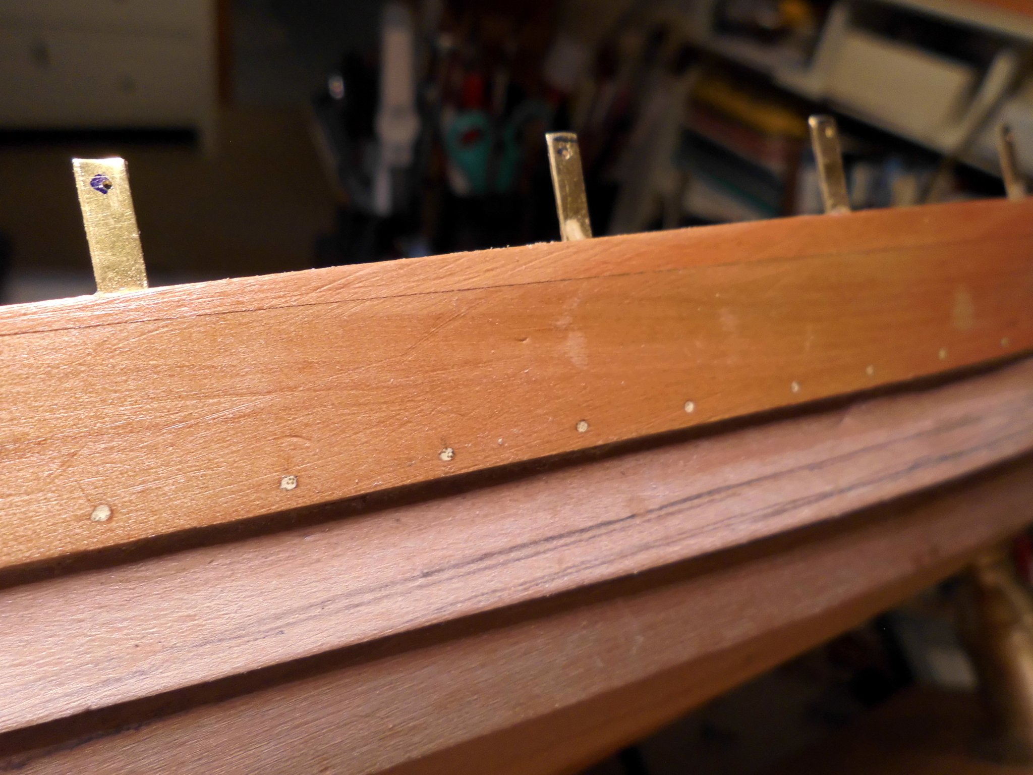
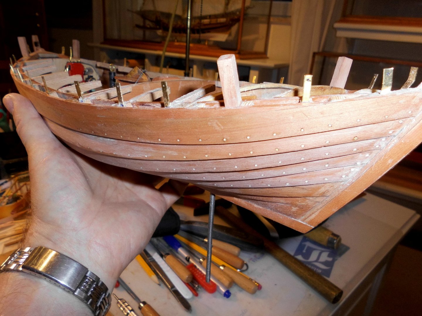
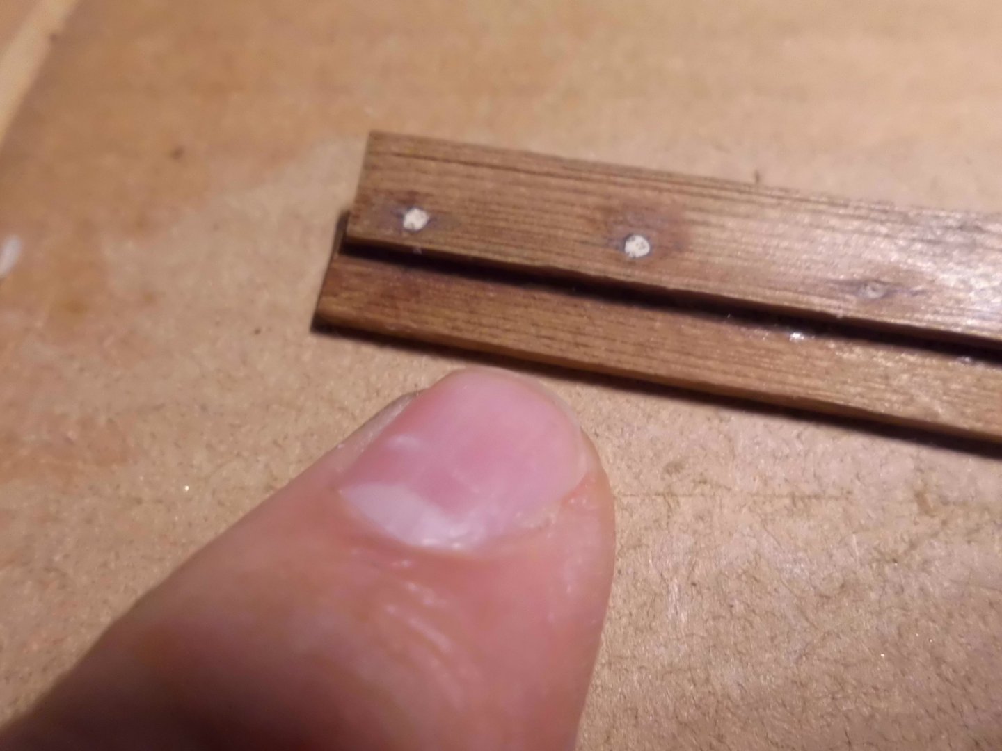
many thanks Pete, Have one side done with the plugs, 3 planks left on the portrside. Trust I`ve never drilled so many holes before. First mark the positions, make a small centering point. drill 0,6 mm. enlarge to 1 mm, place the toothpicks and dip the pointed end in CA before, chisel off the overstanding pics, file and sand flush. I guess that all who did a good looking treenailing on the hulls and decks experienced the same exercise, for me it was new ..... Nils
-
nice work Phil, are you going to rig her, and perhaps with sails ? Nils
-
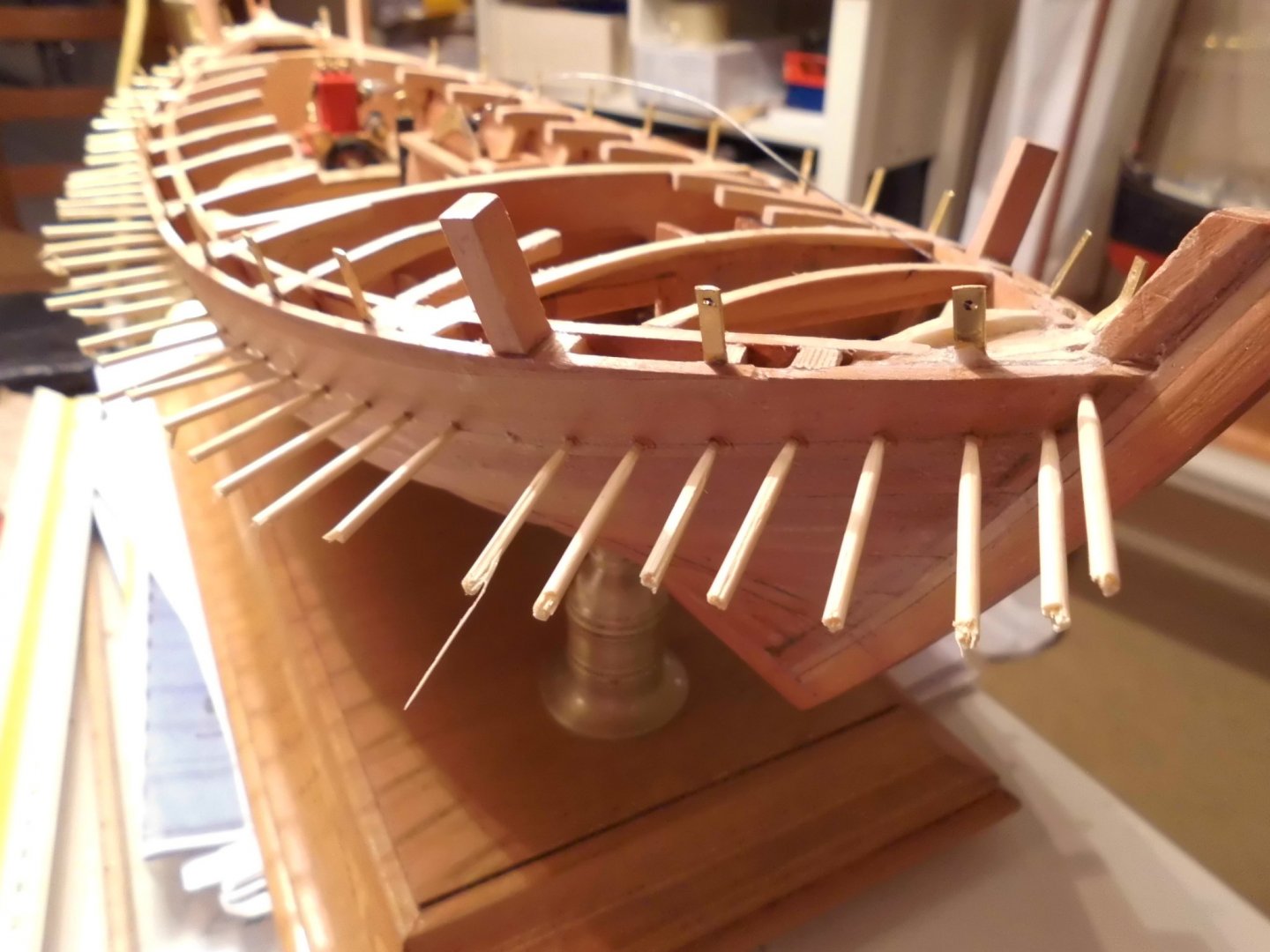
Status: still doing the the hull plank connectors, had to take her off the stand plate for doing the last 3 planks on each side, it works quite well... Nils

- 401 replies
-
- 20
-
-
Many thanks for Geert, and for all that clicked the "likes button"... Geert. yes, I`m also happy with the effect, trust it will look fine above the waterline. (varnished natural wood). At the waterline there will probably be a horizontal white stripe and below that either green or red "anti fouling" coating, I doubt if the plugs in that area will show through the paint, but we shall see later on. Nils
-
Kortes, Wunderbar, congratulations, you`ve built a beautiful ship. She looks so realistic. This little jewel is so well done, rich in detail, very neatly performed and real candy for ones eye to see Nils
-
Lovely work Hof, looking at the fuselage construction, the real plane must have looked somehow the same. One can imagine that unfreindly bullits went through it like through butter... Nils
-
I am enjoying your build log Geert, it looks like a real boat beingset up in the workshop... Nils
-
You`re right Pete, thats why I cut then all off...... Ì`m really pleased with the outcome of the wooden plugs, got all in nice row alignment. The lighter wood color of the picks is a good contrast to the pear planks Now all the others can be done in the same way.. Nils


- 401 replies
-
- 16
-
-
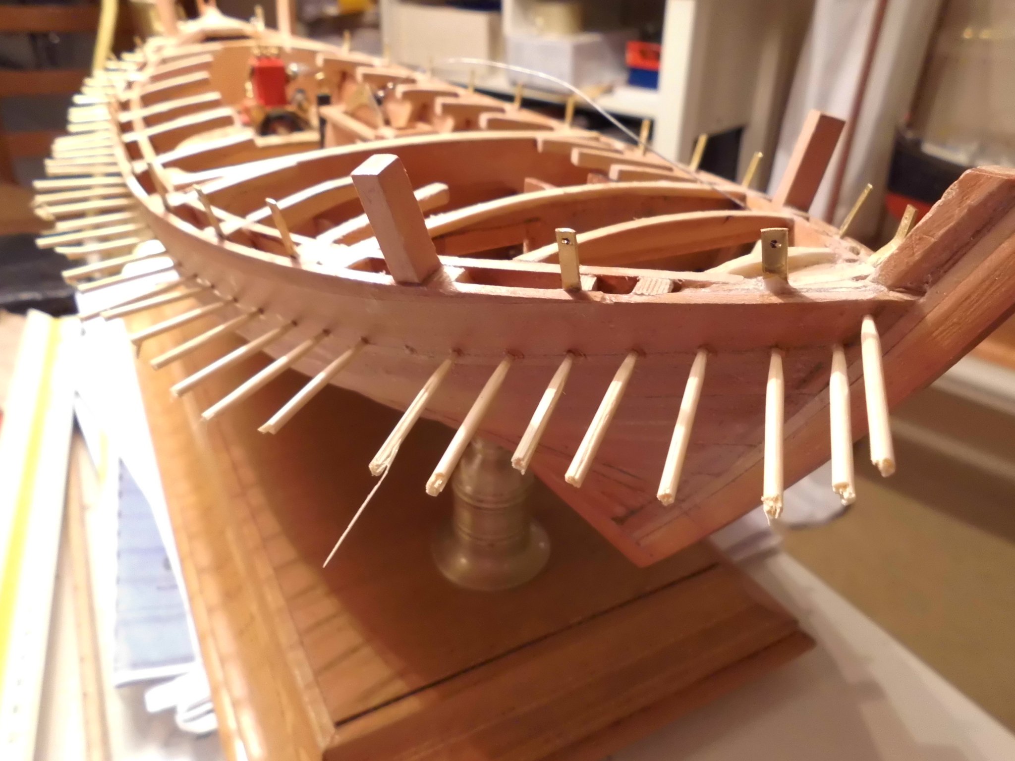
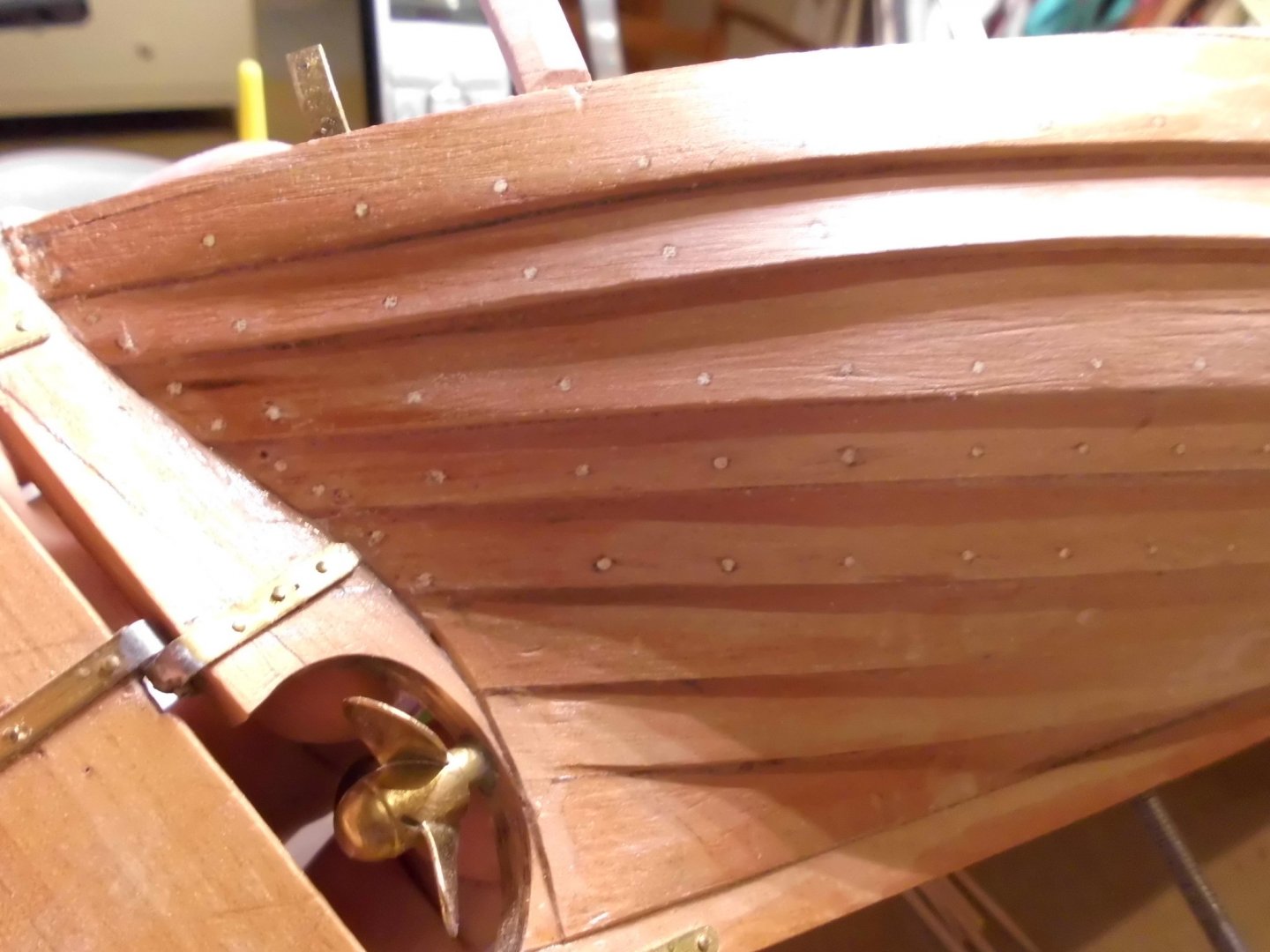
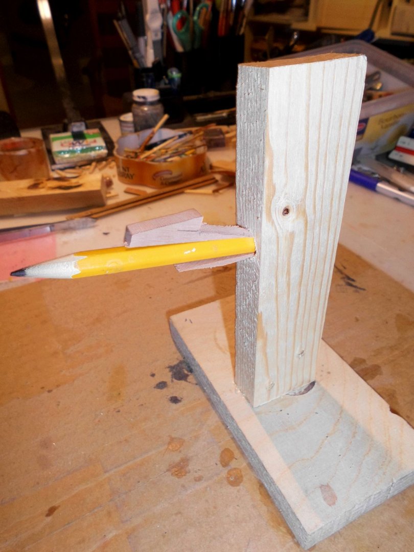
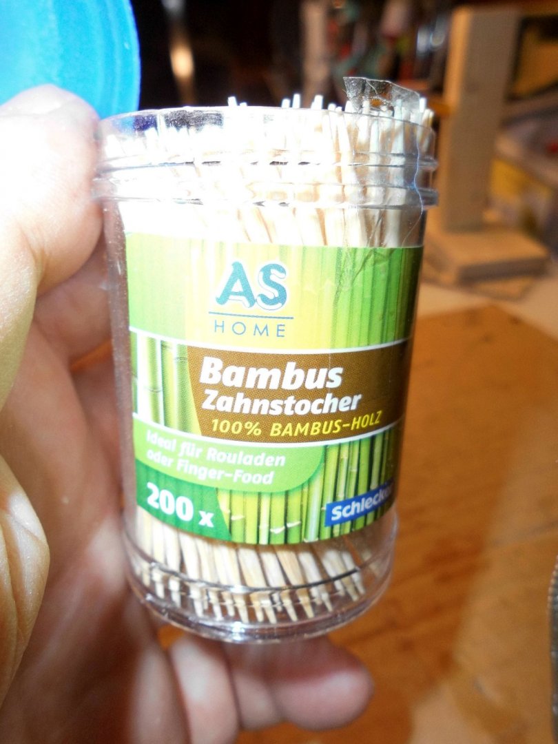
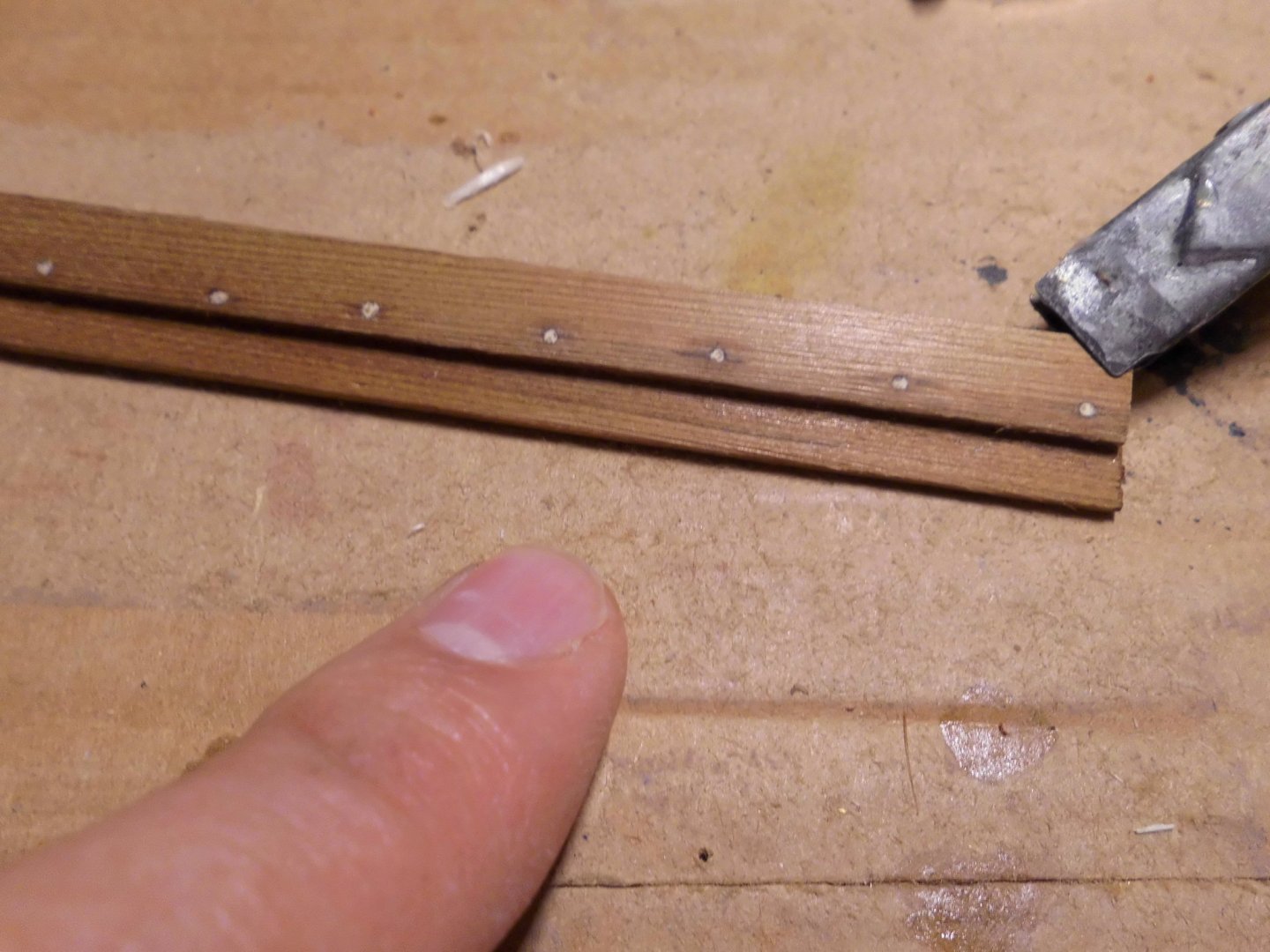
Status : transfering the waterline to the model, and beginning to put wooden (Bamboo toothpicks) into the horizontal, overlapping clinker planks. I did`nt do this before, so its a jump into the cold water. I did my best to get the 1 mm toothpick holes in alignment, starting with the upper stb. plank. Check of the outcome will follow tomorrow, when the toothpicks are trimmed off and the plank sanded over. Nils the little jig for marking the waterline thin bamboo toothpicks a trial with 1 mm holes in the planks (Chose this one) trial 1,5 mm holes ( found them too large) picks glued in lightly with CA
- 401 replies
-
- 13
-
-
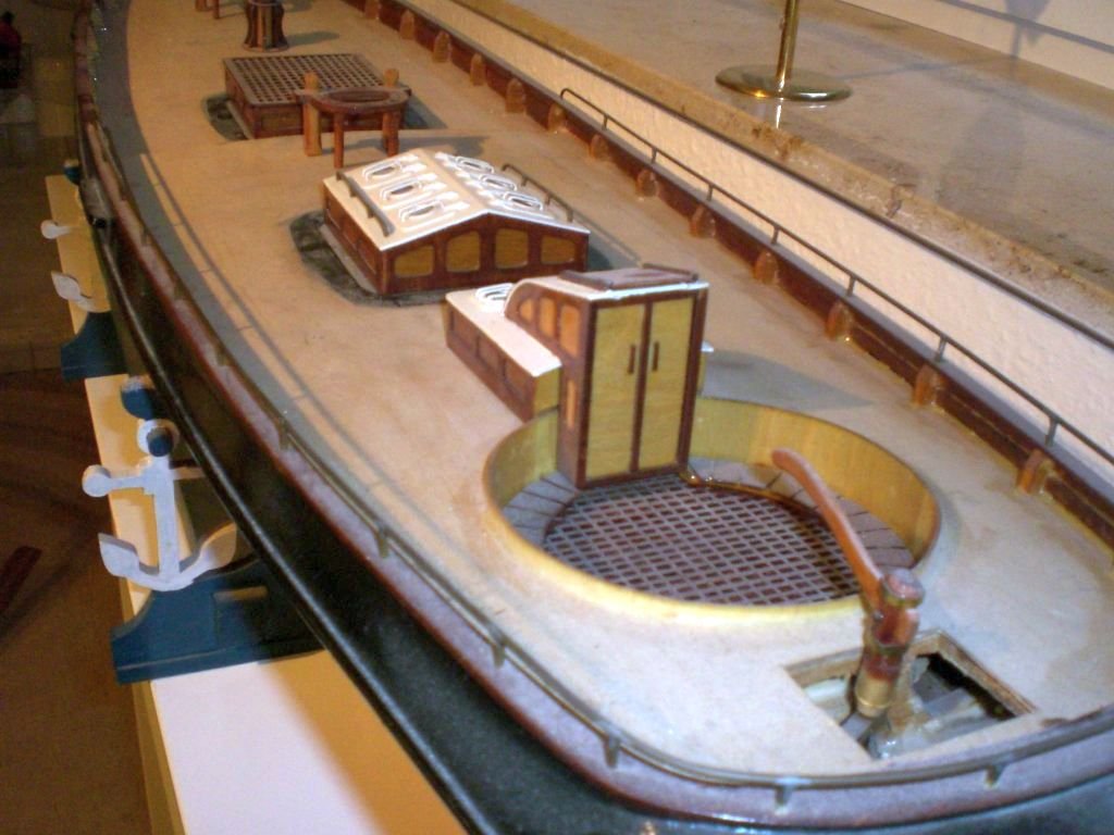
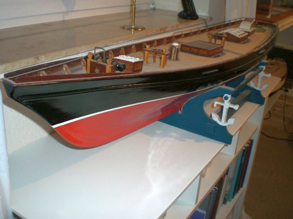
Oh Pete! I do hope my input of the last post did not upset you too much.... Your "Bluenose" will for sure have more displacement capacity to carry a suitable ballast. I will be following your progress with great interest. I wanted to show you what I meant with the lines of the "America" I built, but did not complete. You`ll see why it reminded me of your "Bluenose". Some years ago my PC broke down, and all the personell files, and hundreds of pics, also modeling pics went lost with it. Fortunately I posted to a thread here at MSW to my rememberance, where I found my only still existing pics after searching... Have a nice weekend Nils Yacht America, hull closed and watertght, but not complete, deck and fitting out started.... The length of the hull was about 1380 mm, as long as the sideboard where its standing on 3 Kg extra internal lead-weight made the hull already reach the waterline There were two large hatch plates, under grating and skylight, flush with the deck in order to give access to all RC equipment and winshes etc
-
Thank you very much for your kind words Pete, I see were walking down the same lane, your suggestions for fuel tank, brass filling cap, shiny straps etc, many thanks I`ll see what I can do about it. I was also thinking of placing a steelbarrel with Shell / Mobil Oil,. or so... enblem on it aft, next to the motor. My wife suggested there should be some blue/white checkered pillow cases for the berths of the cabin Nils
-
Good morning Pete, Motor preference, certain make ? Actualy no, the engine I chose was a free chosen fictive engine that would comprise motor housing, gear- and clutch housing, cylinder, shaft, flywheel, front bearing shield, water pump, oil dip stick, starter, generator, mounting brackets, V-belts,cooling- and exhaust tubes, clutchlever and propshaft coupling. I know that some essentual devices will still be missing, such as tank, gasoil injection unit, ignition box, glow plug, etc.... Some time ago I saw a Zeesboat plan being offered at Ebay, It could perhaps be worth searching there or in the web (Google) from time to time. Mathias was using pear wood for planking, and yes, same as you did, I was amazed that neither glue stains nor toolmarks were to be seen there, he is a genius (what a skilled work !! ) What spooks aroung in my mind is, how can I achieve the old fishing workboat character, seeing all the newdays leisure Zeesboot craft. Example the wonderful deck Mathias built would probably be too fine for the fishermens muddy and scratchy boots and scraping network and fishing equipment .... I must admit that a strong criteria for me is also ( in lack of carving or clay modeing skills), to choose the scale for the boat due to the scale-true crew figurines. Here I found two figures from make "Pola" which are actualy forseen as driver and stoker ( now converted to fishermen father & son) on scale "G" steam locomotives scale 1: 25 resp. 1:24 Nils
-
Good morning Pete, thanks for sharing your progress, I very much admire your large version of the "Bluenose" you are at,.....it reminds me a bit of the schooner yacht "America" I built for RC in about the same large size. I wated to build a boat that could be seen, out on the water. The hull was plank on ply frame from mahagony wood planking, and to get her 100% watertight, coated with glasfibre roving mesh and epoxyd resin. The hull had true shape, was very sharp cut and grazile, and I already during the build had doubts if later on I could get enough inboard lead ballast inside at the lowest possible point, stradeling the keel and the neighboured frames. When the first time in water, I was quite disappointed that although the hull itself was a lightweight, the waterline was already reached with appr. only 3 KG inboard lead ballast, (which would have been far too light for the large sail area to compensate). So the ship without the ballast went to the shelf. I sold it many years later to a modeling enthusiast in Hamburg and never saw or heared about it after that. Trust that an removeable exterior fin keel with lead bulb would have been the better choise Wishing you good success with the "Bluenose". The Billing boats Bluenose, I still have, was one of the first models I made when I was much younger, because I fell in love with the lines of this beautiful "Glouster Fisher" of the Great Banks Nils
-
Hi Pete, looks like you caught fire ! I support your comments about Mathias`s incredible Zeesboot, (on the Wettringer Forum), the other models or kits on the web did neighter increase my blood pressure nor inspiration, when I was in search during the preparation phase... Yes, stove and brown sails will be fitted to my boot. Perhaps the tuc engines of this link my be of help for you.. https://www.google.de/search?q=motor+für+tuckerboot&tbm=isch&tbs=rimg:CZvm-n2O-5dKIjjbCOifzC0BAlN6qR5gvc4yYiY_1XGOB9zG2kcw8pLPYyn3bVL7fLsQ2os2dtNzkpTZVDm5xPZ8dRyoSCdsI6J_1MLQECESTtdxsp8H9OKhIJU3qpHmC9zjIRlv77B3HXNLAqEgliJj9cY4H3MRHVP81PFIN6gSoSCbaRzDyks9jKEWcdG2mlO89IKhIJfdtUvt8uxDYR6KaW5244AmgqEgmizZ203OSlNhFYVrV6xZvZNSoSCVUObnE9nx1HEZ31TLmYJgbC&tbo=u&sa=X&ved=2ahUKEwjKvtKr2fPiAhUPLewKHdYkDKAQ9C96BAgBEBg&biw=2133&bih=1022&dpr=0.9 Nils
-
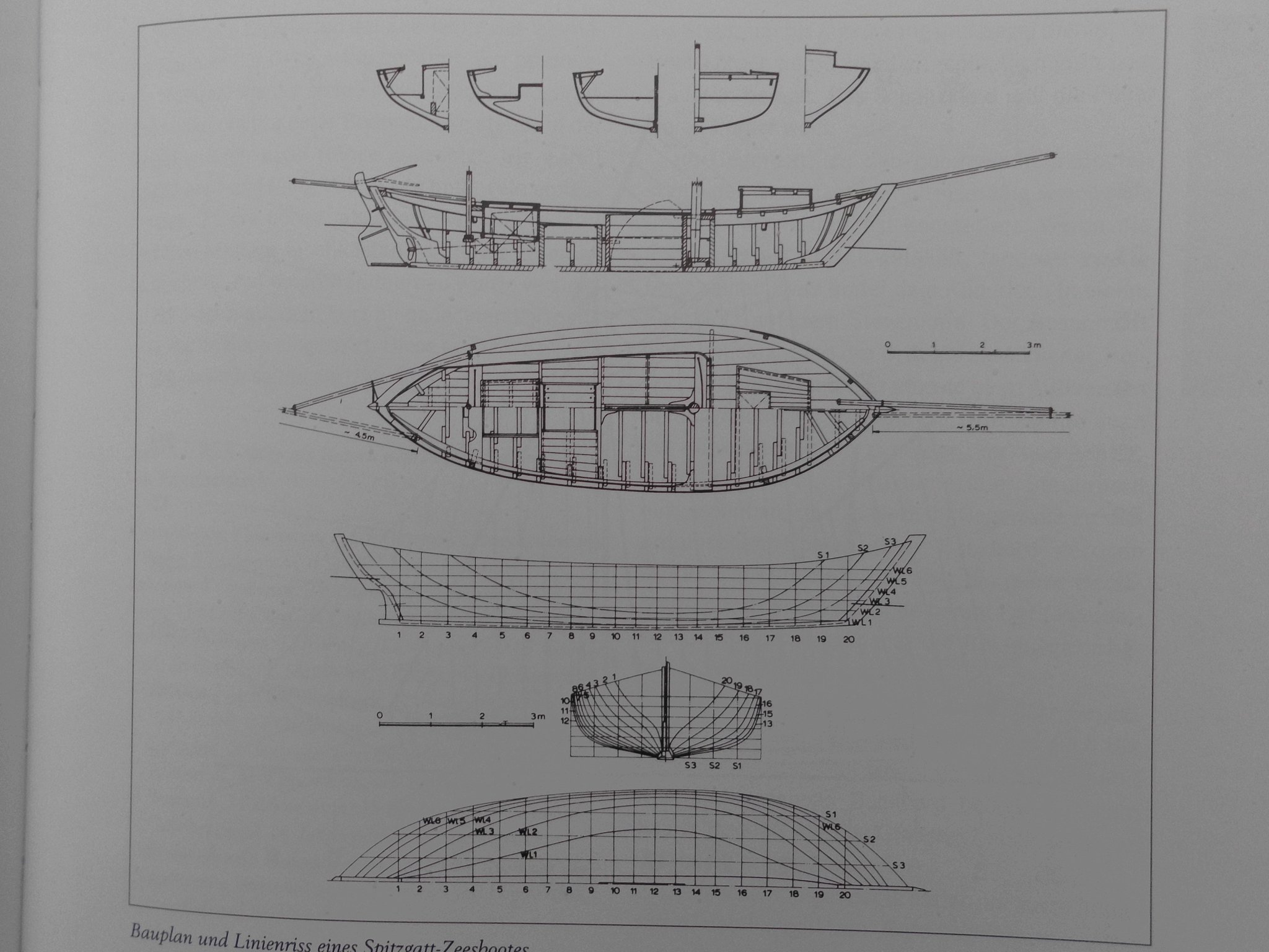
Good morning Pete, I shall be very pleased to see another Zeesboot to be laid on Keel here at MSW, and shall be pleased to help you in this evaluation period....., now to your questions... Cheers, Nils Model dimensions: The model in scale 1:24 is 495 mm long between the posts, will be appr. 750 , mm aver all (bow- and aft spars) Mainmasthight appr. 490 mm Beam 155 mm There are several books available, two of them I am using, and can recommend they are : -Zeesboote Segler durch die Zeiten, by Hermann Winkler - Erlebniswelt Zeesenboote, by Timm,Stütz this one also contains the overview plan I am basicly using, as well as the overview from the web, both motorized, one with fish containment boxes placed left/right of the centerboard if I`m not mistaken this build is from the web page : https://www.modelships.de/Zeesenboot/Zeesenboot_dt.htm


.jpg.7b88533c3651710ed5c6a5dc73a20d4e.jpg)
.jpg.ee60c9406c90387fb6f72ef4e1144e82.jpg)