

bolin
-
Posts
479 -
Joined
-
Last visited
Content Type
Profiles
Forums
Gallery
Events
Posts posted by bolin
-
-
Back to the workbench again. It has been some weeks of very little building. Mostly because we got access to our new vacation home in the beginning of August.
Now I have managed to finish the chain plates.
- Wintergreen, clearway, Paul Le Wol and 3 others
-
 6
6
-
5 hours ago, DocRob said:
I really like larger scale vessels, as there are better possibilities to show fine details, like you do in your build.
Thanks Rob. Unfortunately, larger scale also mean larger model to display😀 I’m not really sure where I will put it when it is finished.
- clearway, Keith Black and DocRob
-
3
-
-
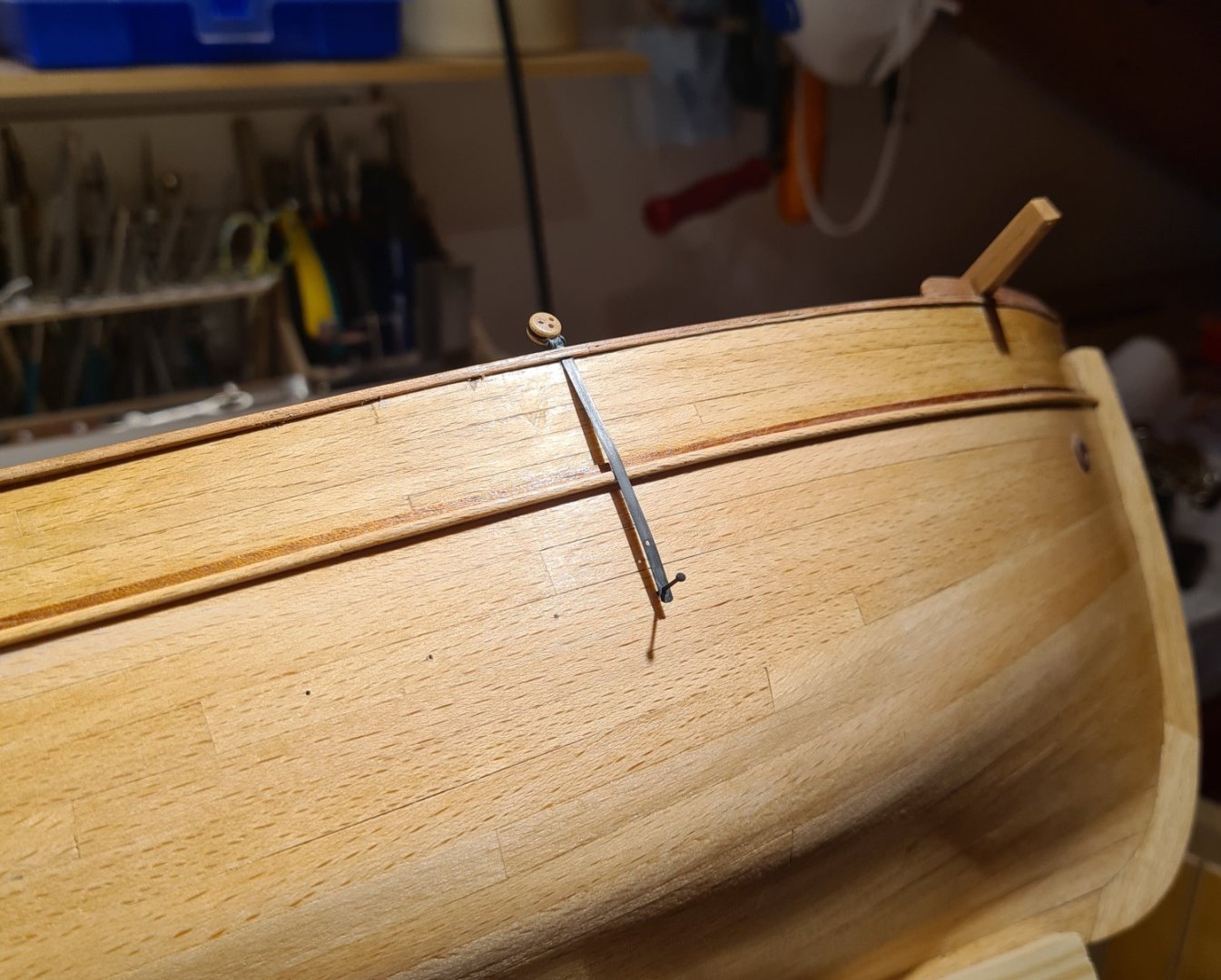
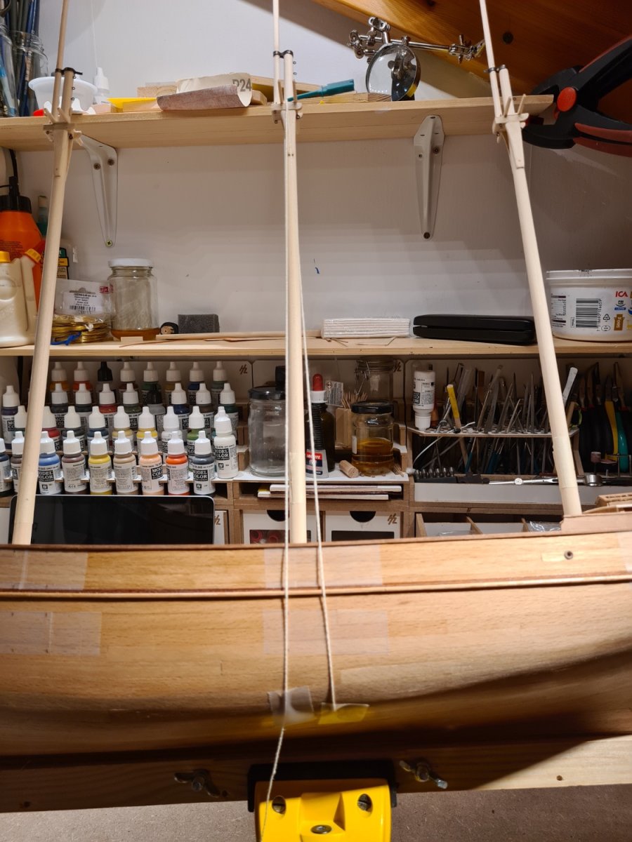
Measuring the position and angles of the chain plates. To protect the hull, and to have something to draw on, I put som tape on the sides.

The chain plates are made from strips of brass. In the end of each strip I made a loop and soldered it closed. Then I filed loop down to about 1 mm width.
The chain plates should go through the hand rail. So I drilled, carved and sawed slots along the railing. I managed to do that without splitting the walnut of the hand rail. I think I was fortunate that I had to laminate the handrail from two pieces of 1mm sheets, that made it less prone to splitting.
In the picture below I have also drilled holes for the rivets.
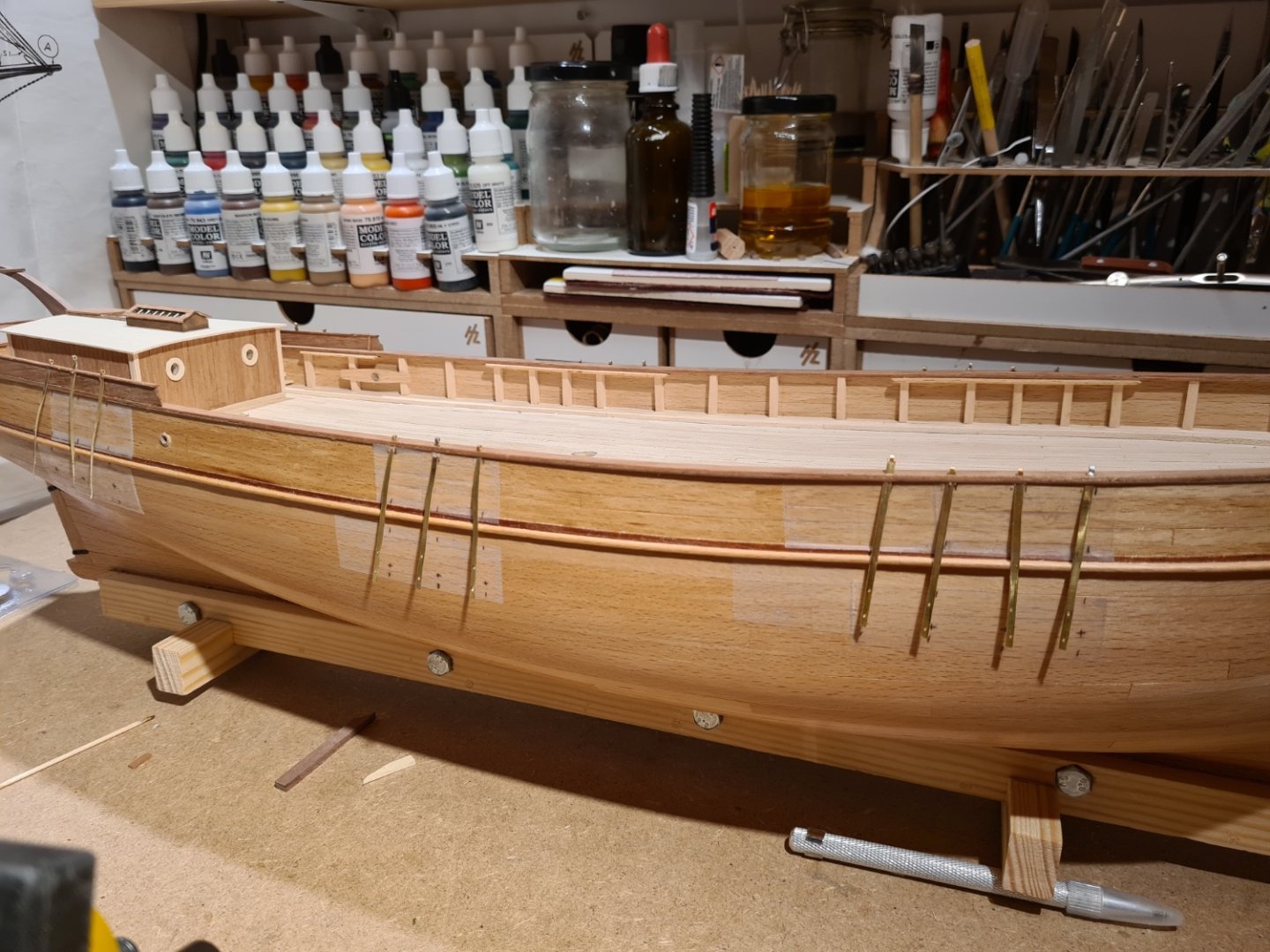
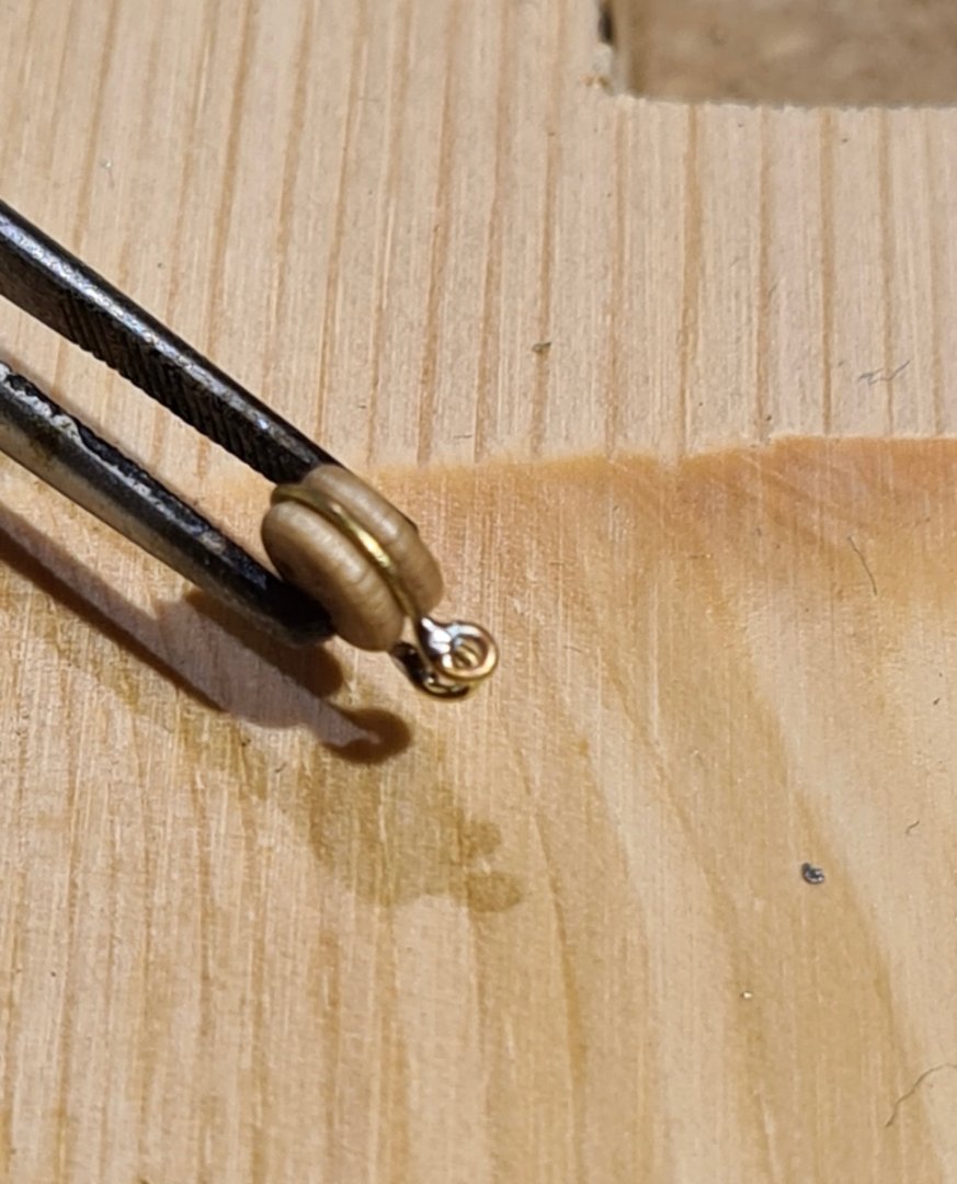
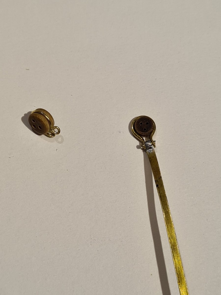
The deadeyes shall be attached to the chain plates with metal bands. I have experimented with two options. In the one on the right, I flattened the end of a brass wire, and made holes for a rivet. In the method to the left I made loops on the end of a thinner brass wire. This is the method I chose. This method seems a bit easier and more repeatable.

With a bit of solder, the loops will probably be strong enough.
- Keith Black, Wintergreen, clearway and 4 others
-
6
-
 1
1
-
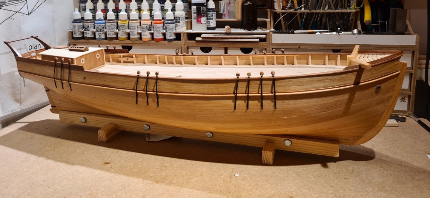
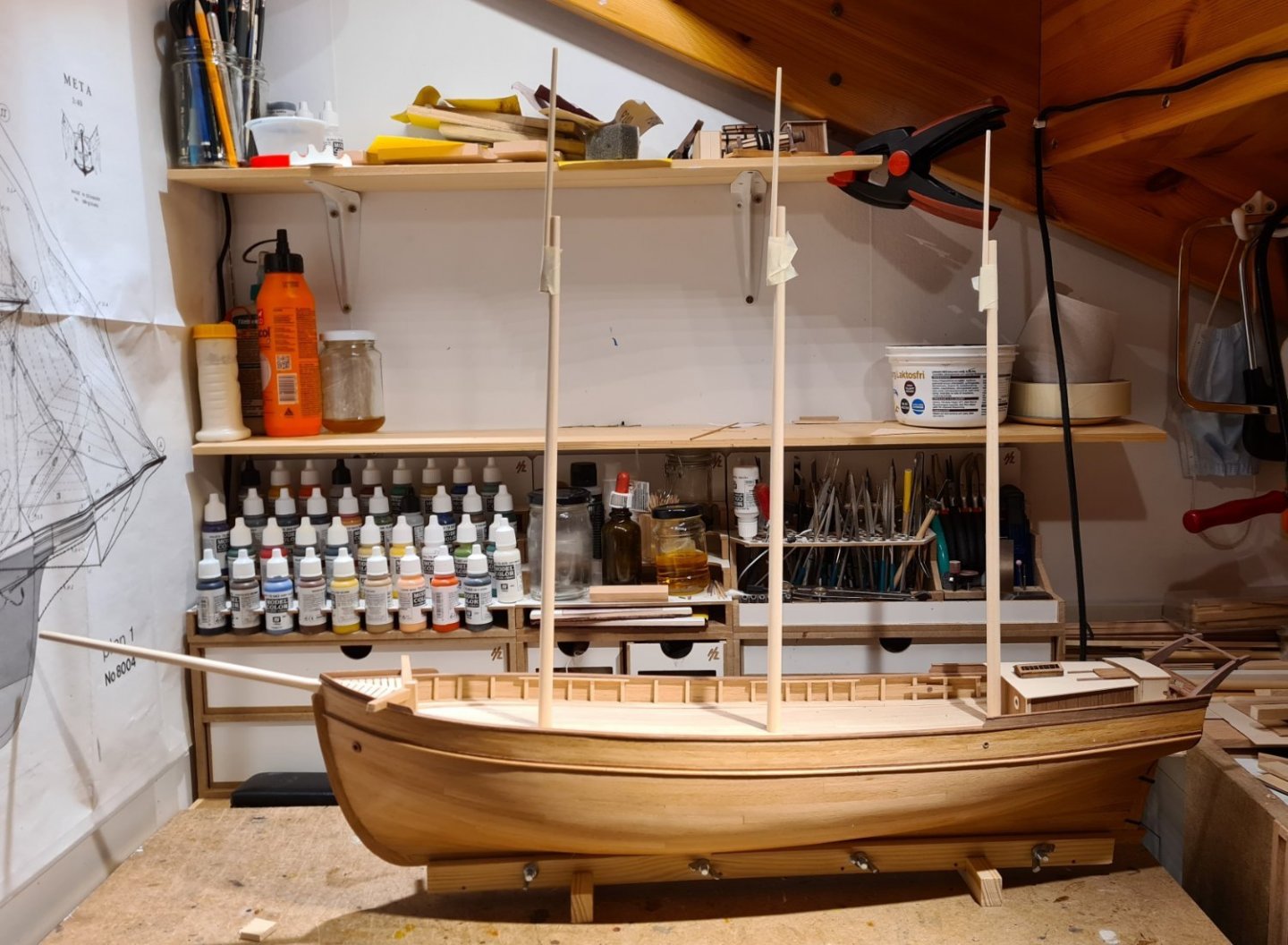
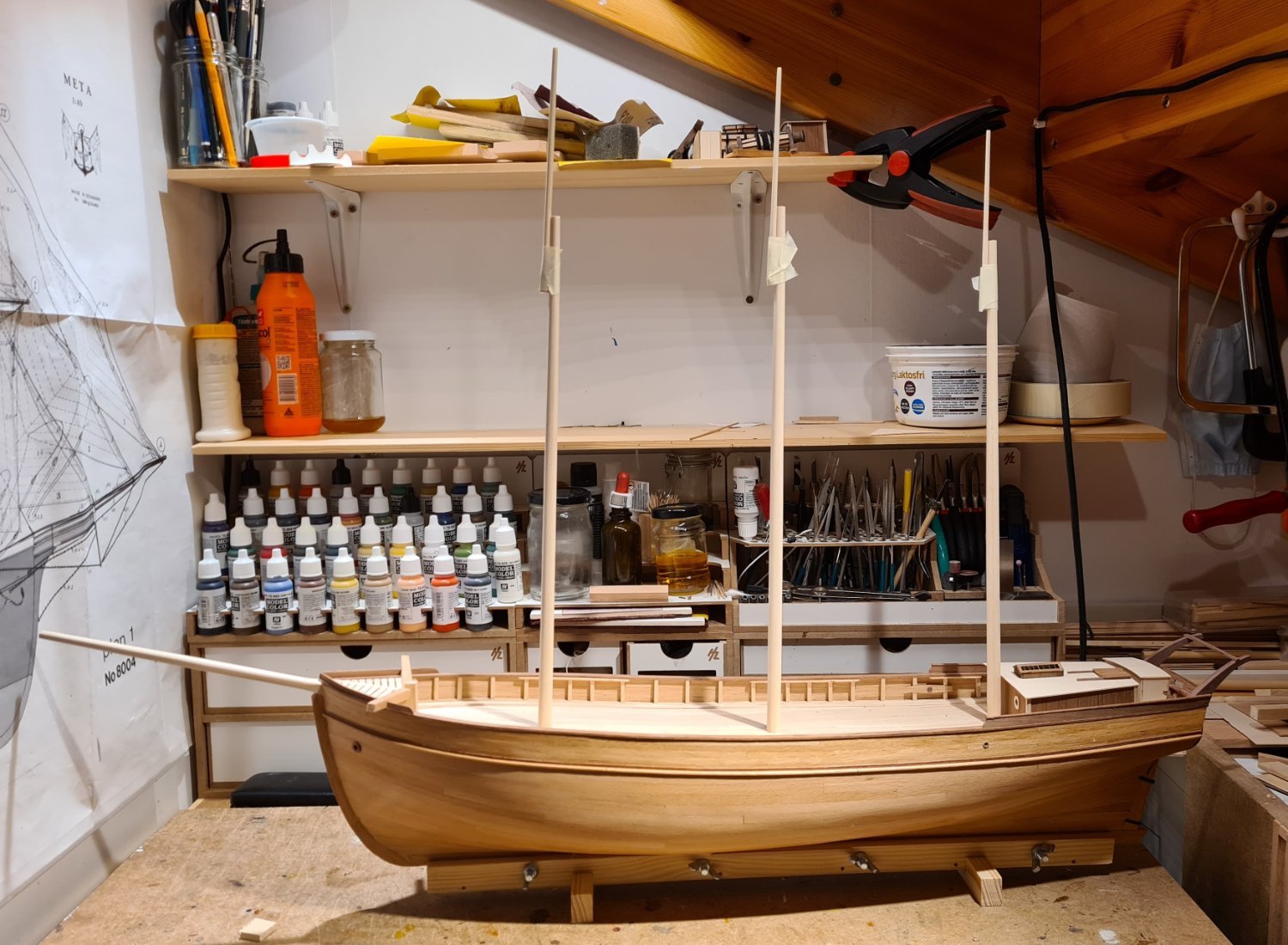
It is starting to come together.
Most individual parts are completed, only the windlass and the bowsprit has e bit of metal work to be completed.
Now the assembly will start. No parts are glued in place yet, I have waited until the masts are done so that I can determine exactly where the chain plates should go. That is what I will continue with next.

-
-
Thanks Keith!
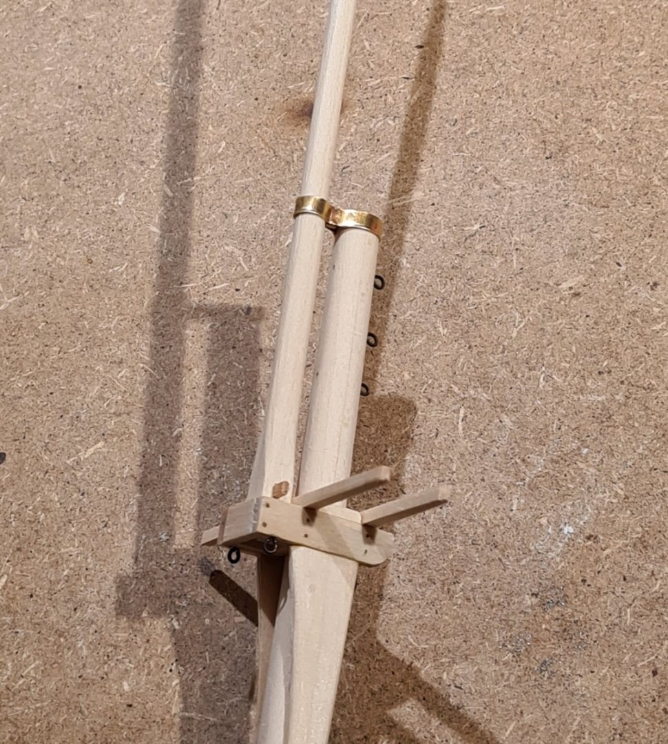
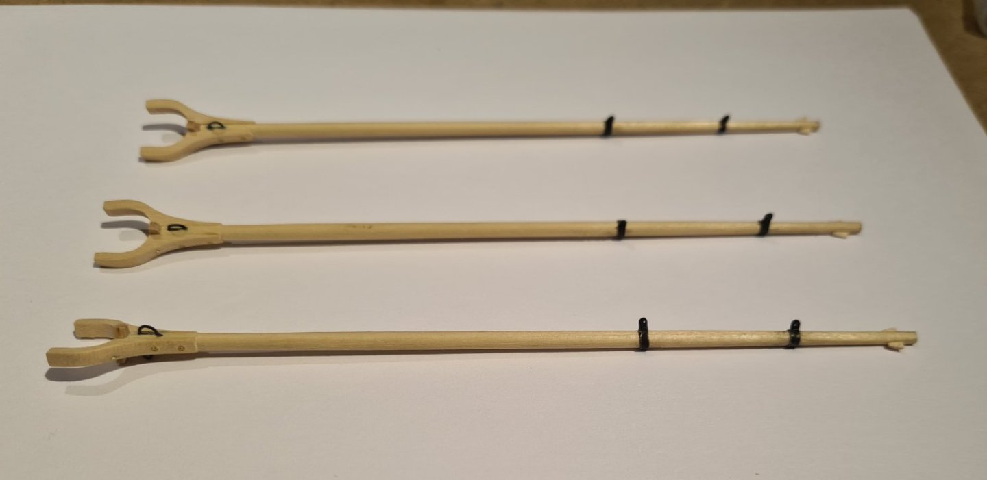
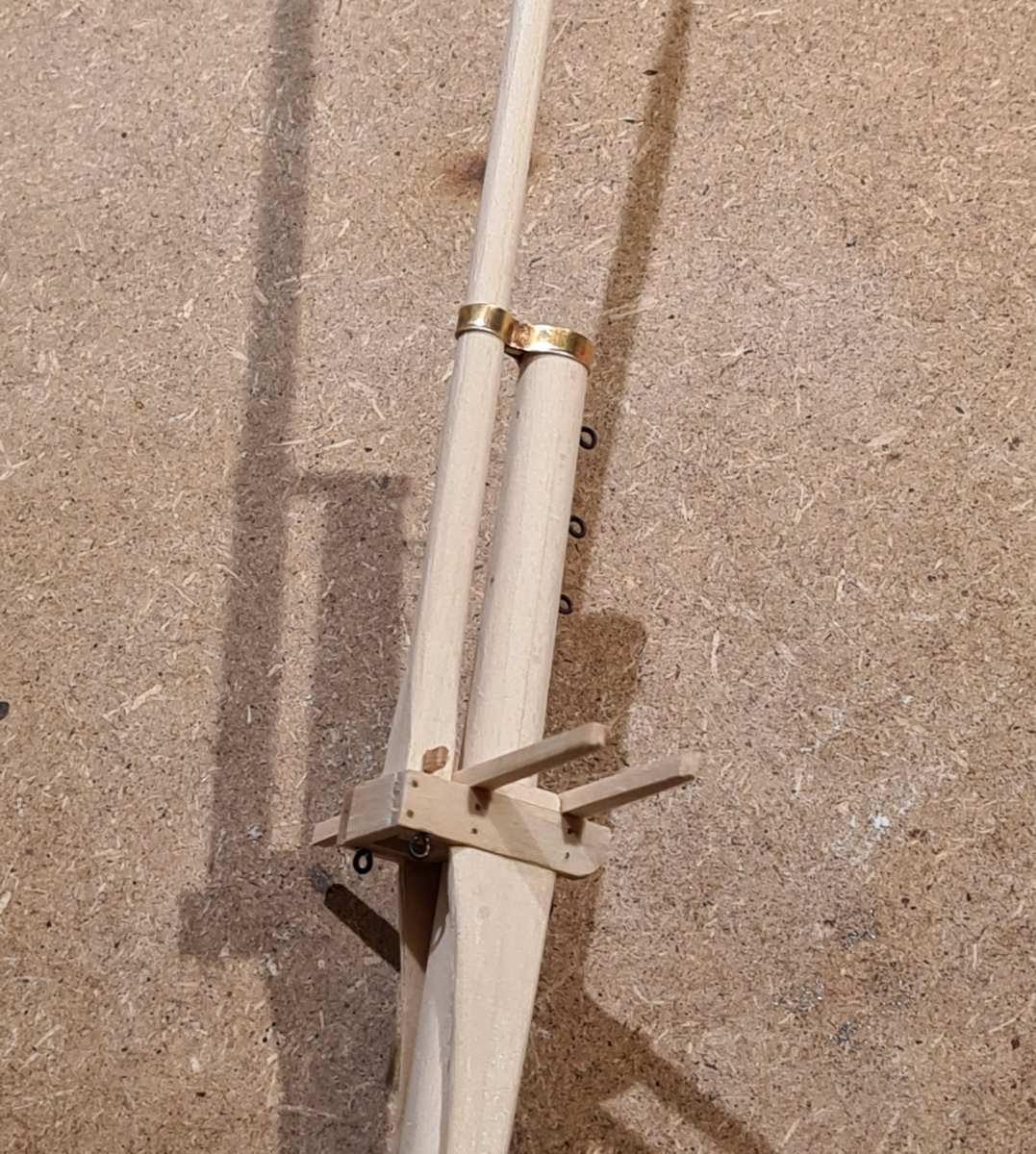
The next step is the trestle tree, cross tree, cheeks and topmasts. The topmast are mostly complete since before. I only need to narrow down the pole section and create a shoulder there.


- clearway, Wintergreen, Keith Black and 3 others
-
6
-
Thanks for the likes😊
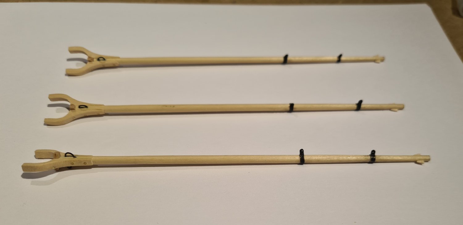
I have worked with the booms in parallel with the gaffs, so now they are finished too.
A part of what has taken so long is to figure out how to work in brass. The (working) hinges and the spindle band is the most intricate assembly I have made thus far.
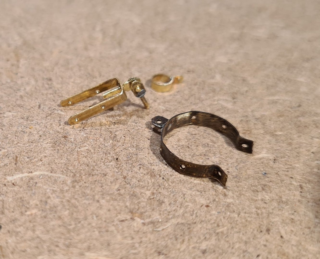
The final booms, after blackening and a bit of touch up paining.

Cheers
-
A brief update, the gaffs are finished.
- Peanut6, Wintergreen, yvesvidal and 3 others
-
6
-
This time of year, there is not so much time for modelling. Here in Sweden, the short summer means that you don't want to waste it with too much indoors activities. But sometimes it rains... So a few things has been happening on Meta.
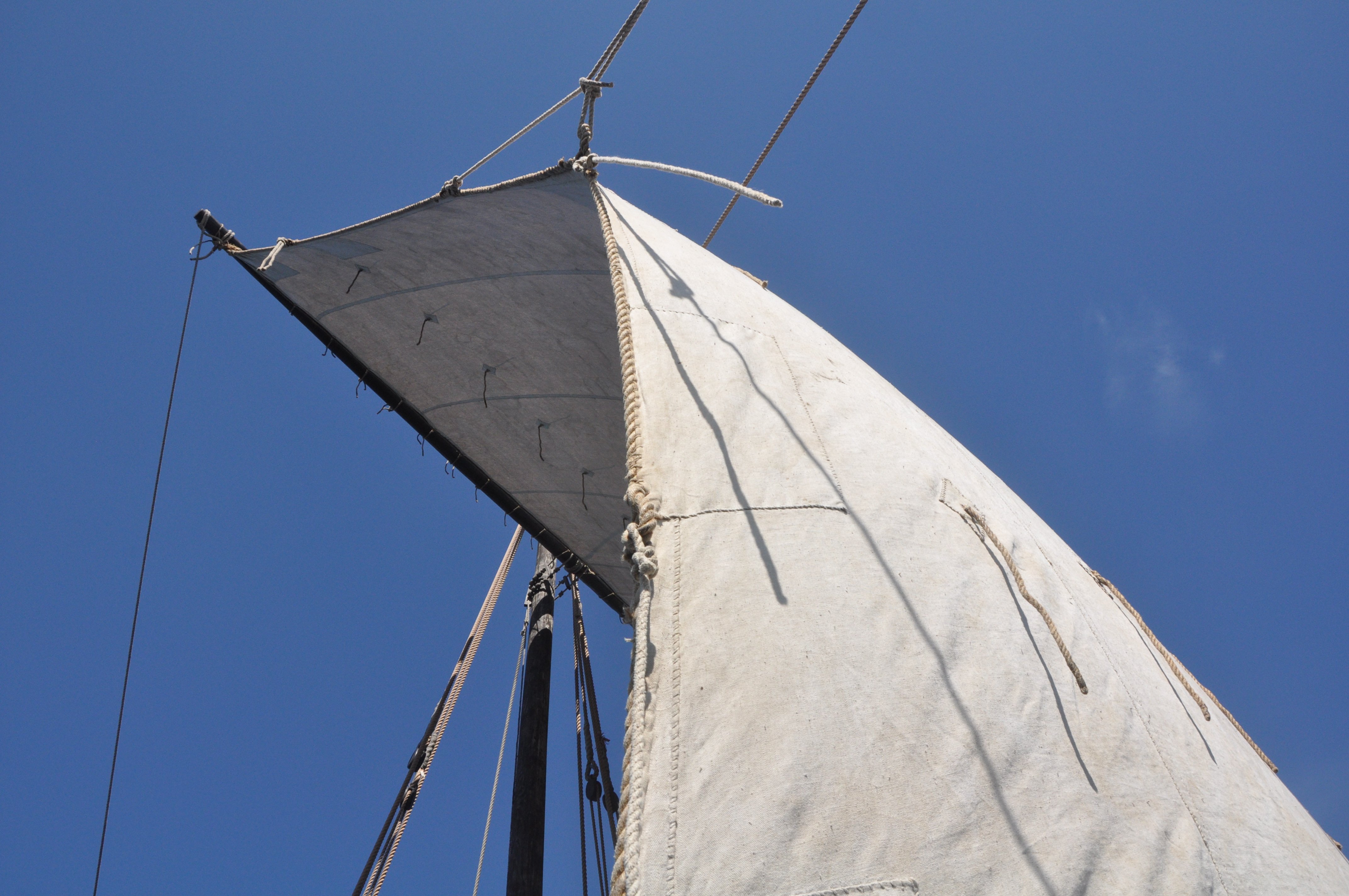
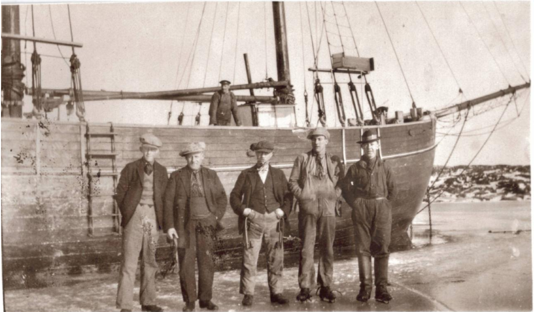
I continue with the masts and spars. There are a number of details that needs to be decided. This picture seems to correspond well with how Metas fore mast must have been rigged when built. We can observe a number of details, such as internally strapped blocks, standing rigging of steel wires and a fair bit of metal pieces.
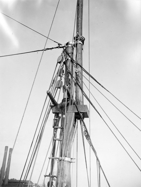
I have not worked much with metal, and I basically only have hand tools. There is a bit of learning to be done...
Here are some initial pieces, a start of spider bands for the masts. And start of bands to attach lifts for the booms.
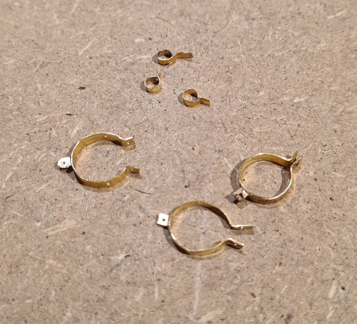
I have also started with the gaffs.
- Peanut6, clearway, Wintergreen and 3 others
-
6
-
Glad to see an update, and to hear that you feel better.
-
-
The lack of detailed documentation has forced, and inspired, me to a lot of extra research. By this I have learned a lot. More than if I would have built from fully documented source, an accurate kit or a monograph. I quite enjoy the research, and most of the future builds I’m thinking about will require (at least) the same.
- Peanut6, Keith Black, clearway and 1 other
-
4
-
Thanks Keith. It certainly looks strange. I think I’ll make a new fore top mast, and move the one I have to the mizzen. I actually have another photo, where the mainmast is is the tallest one. Unfortunately, I don’t have dates on the photos. It’s hard to be certain about the evolution of the ship.
In the end I think I will not be able to label the build “Meta”. Instead it will be “Baltic schooner, circa 1915”.
-
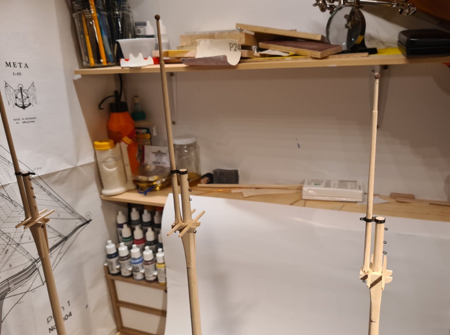
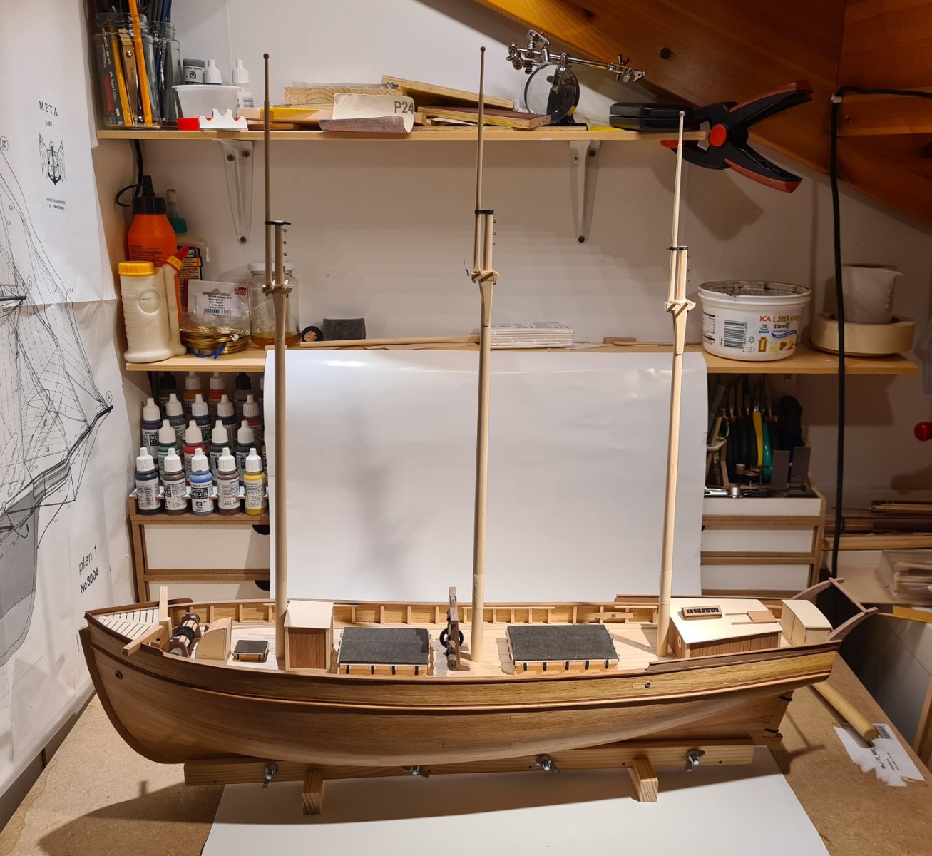
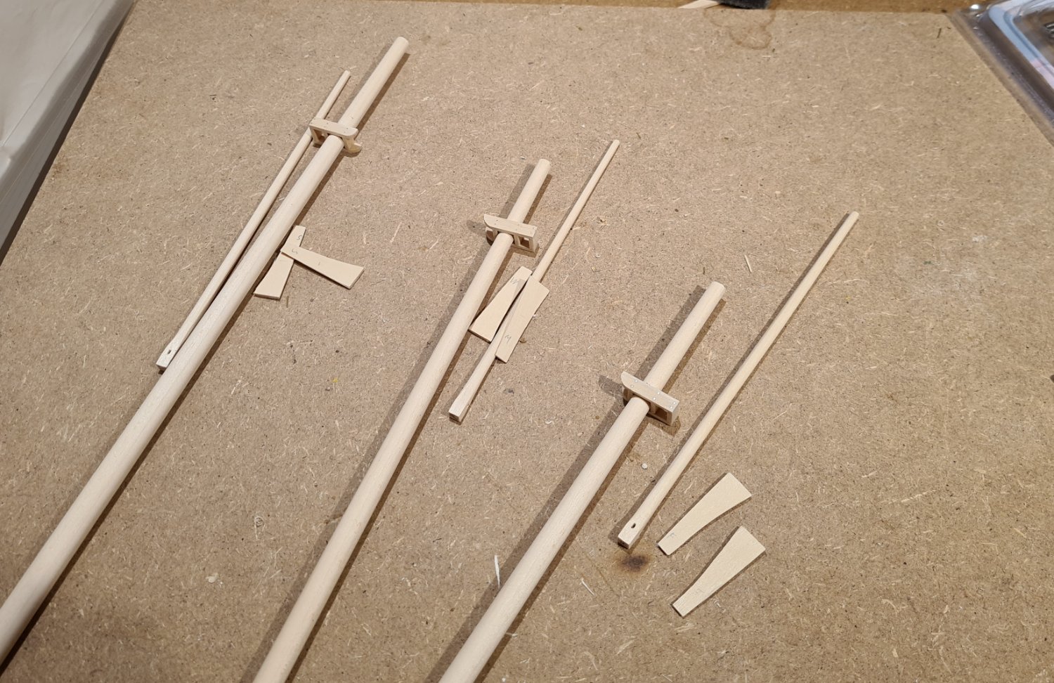
Continuing with the masts. Before I permanently mount the deck fittings and buildings, I like to check with the masts, booms and gaffs to see that the proportions look ok.
I have derived the lengths of the spars from a photo. I know the length of the hull, and by relating that to the masts and other part I have an idea of the lengths.
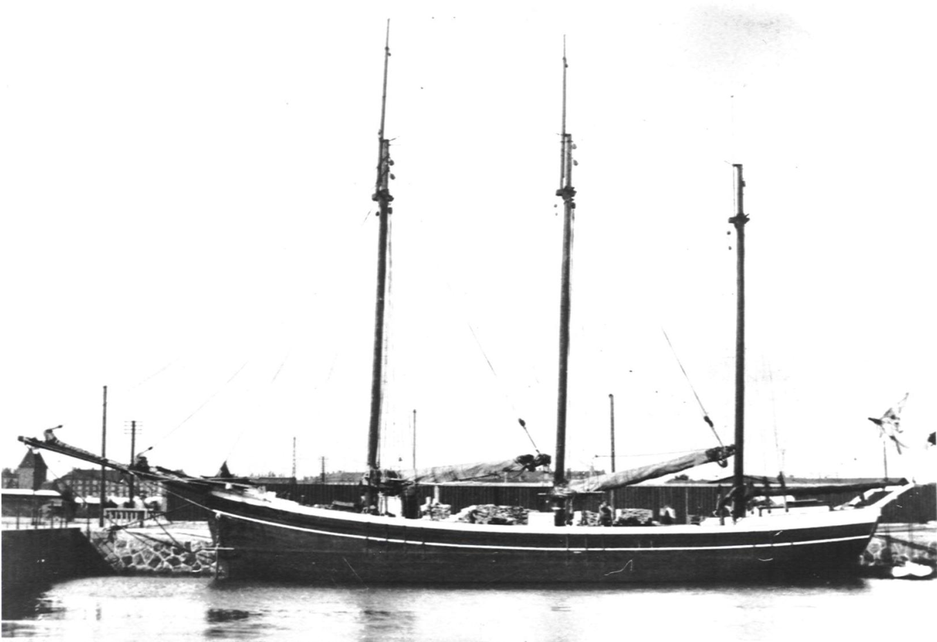
The topmasts are relatively short, even compared to other schooners from the same time. Especially the mizzen topmast looks very short and thin. This may not have been the original. I have read that when other schooners and barques were motorized (typically in the 1920s), they became unbalanced under sail. The propeller caused a drag. A common remedy was to reduce the rig on the mizzen mast by replacing the mizzen topmast and removing its topsail.
Since I want to represent the ship as it was originally built, I'm considering adding a taller mizzen topmast. The picture above is most likely from after the first motor was installed.
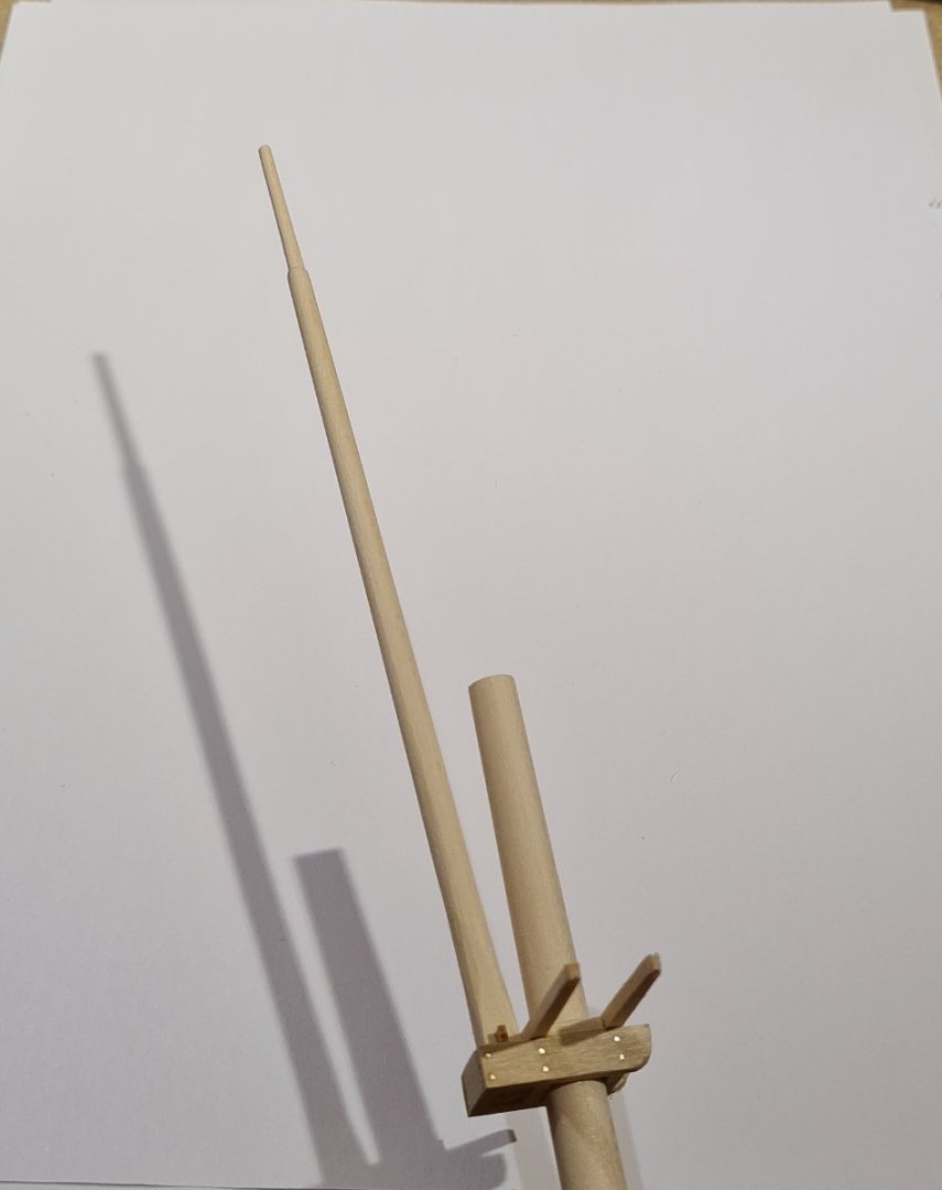
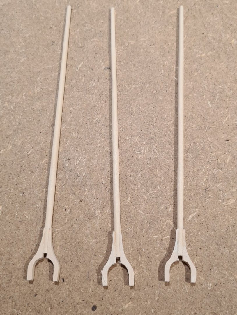
I made the mast from square lengths, and reduced them to the correct proportions. First to square cross-section, then to octagonal. The diameter along the length I got from the formulas in Underhills "Masting and Rigging The Clipper Ship and Ocean Carrier".
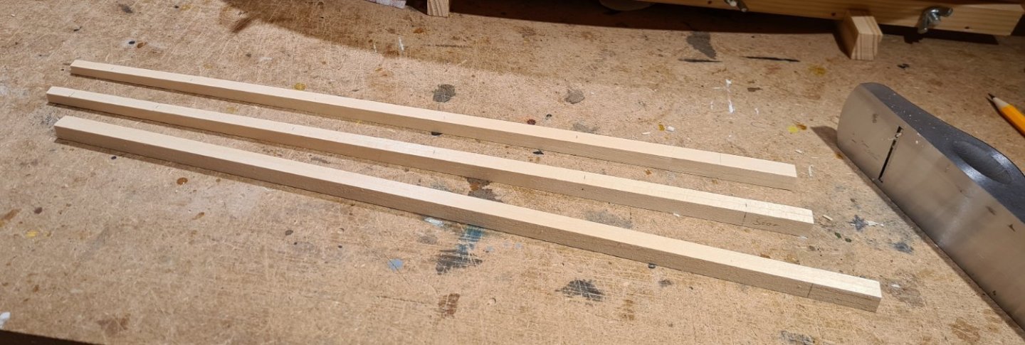
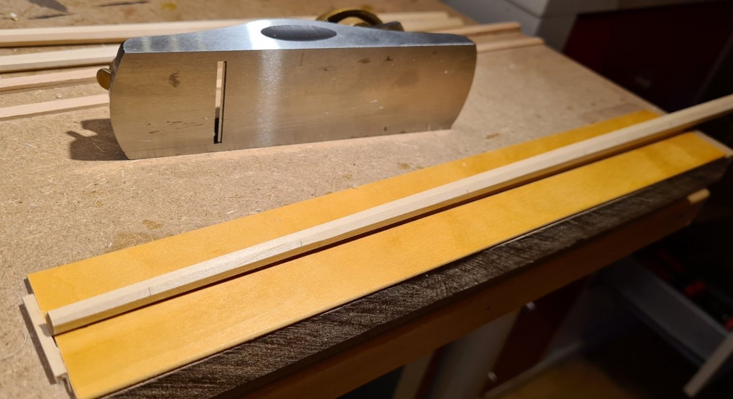
The final rounding was done by putting the octagonal pieces in an electric drill and while holding a sandpaper in the other hand.
The (temporary) final result. I think I will make another mizzen topmast to see how it looks.
- Peanut6, Wintergreen, bruce d and 7 others
-
10
-
-
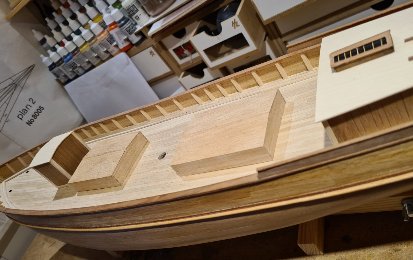
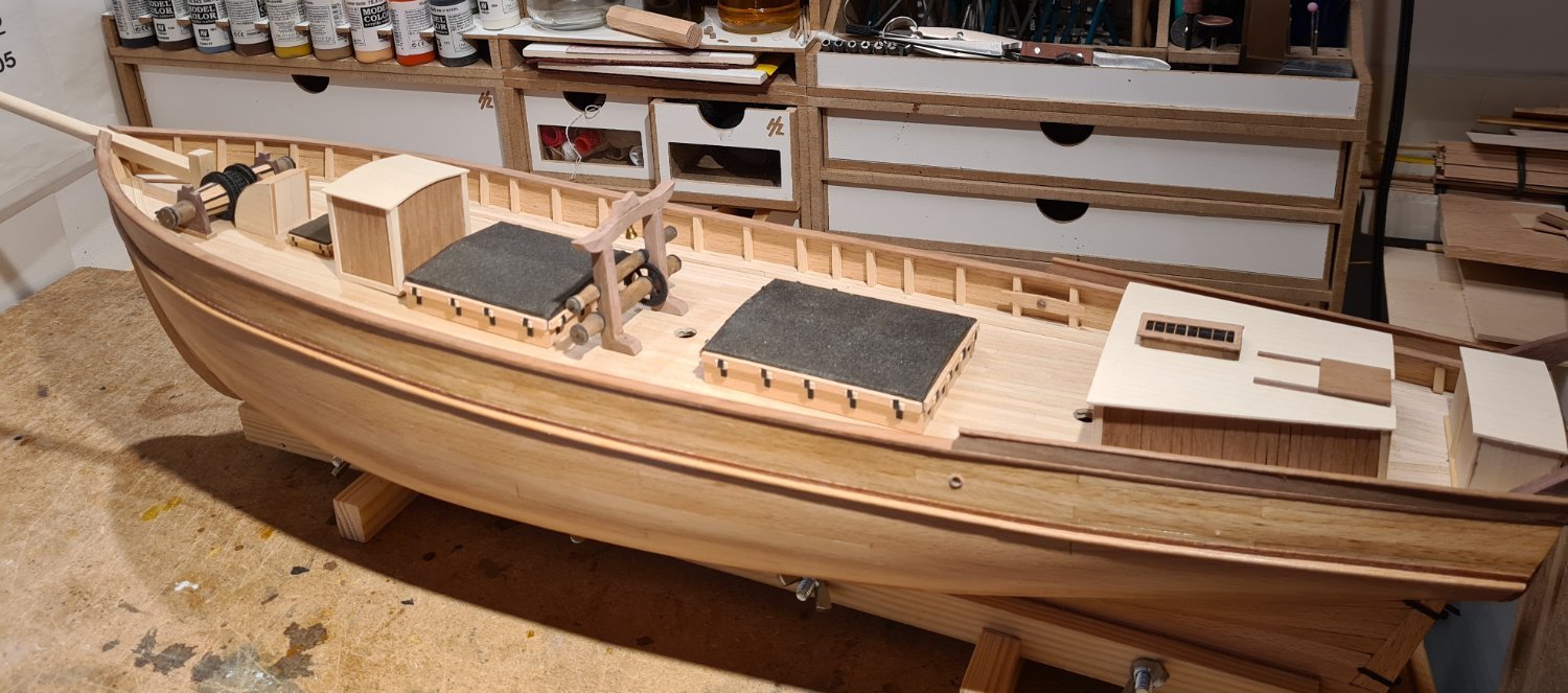
Time for another update. I have continued forward on the deck with fittings and equipment. Nothing has been permanently mounted yet. I want to see everything together first, to check that the proportions looks good.
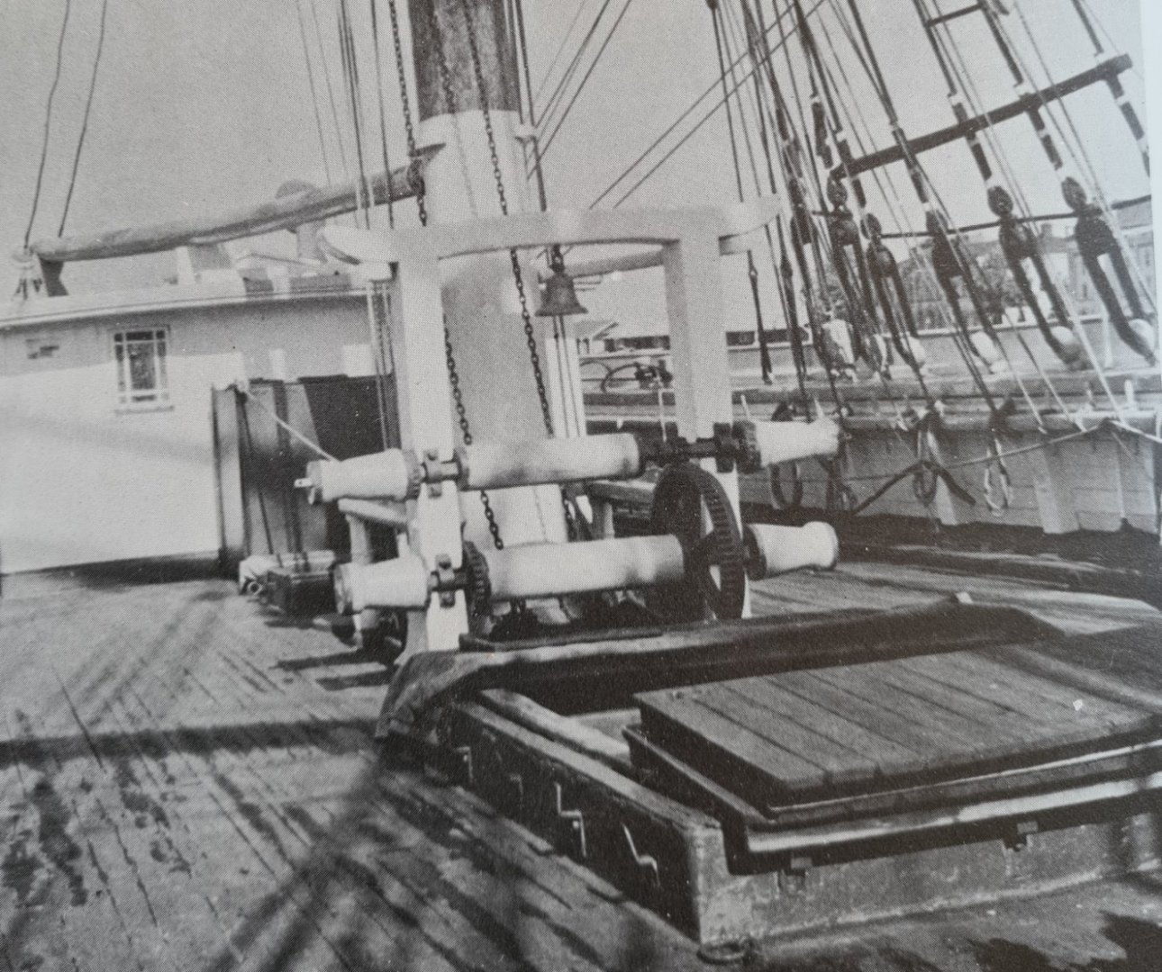
In this photo, we can see the top of the windlass. Nothing else of the area in front of the fore mast can be seen above the railing. I need to make an educated guess.
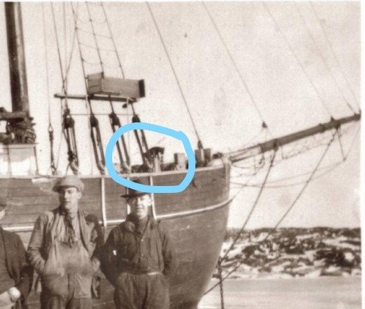
I have decided for something similar to the layout shown in the following photo. It is from another schooner from about the same time. It shows the windlass, a companionway and a hatch. There are also two bollards at the railing, similar to the photo above.
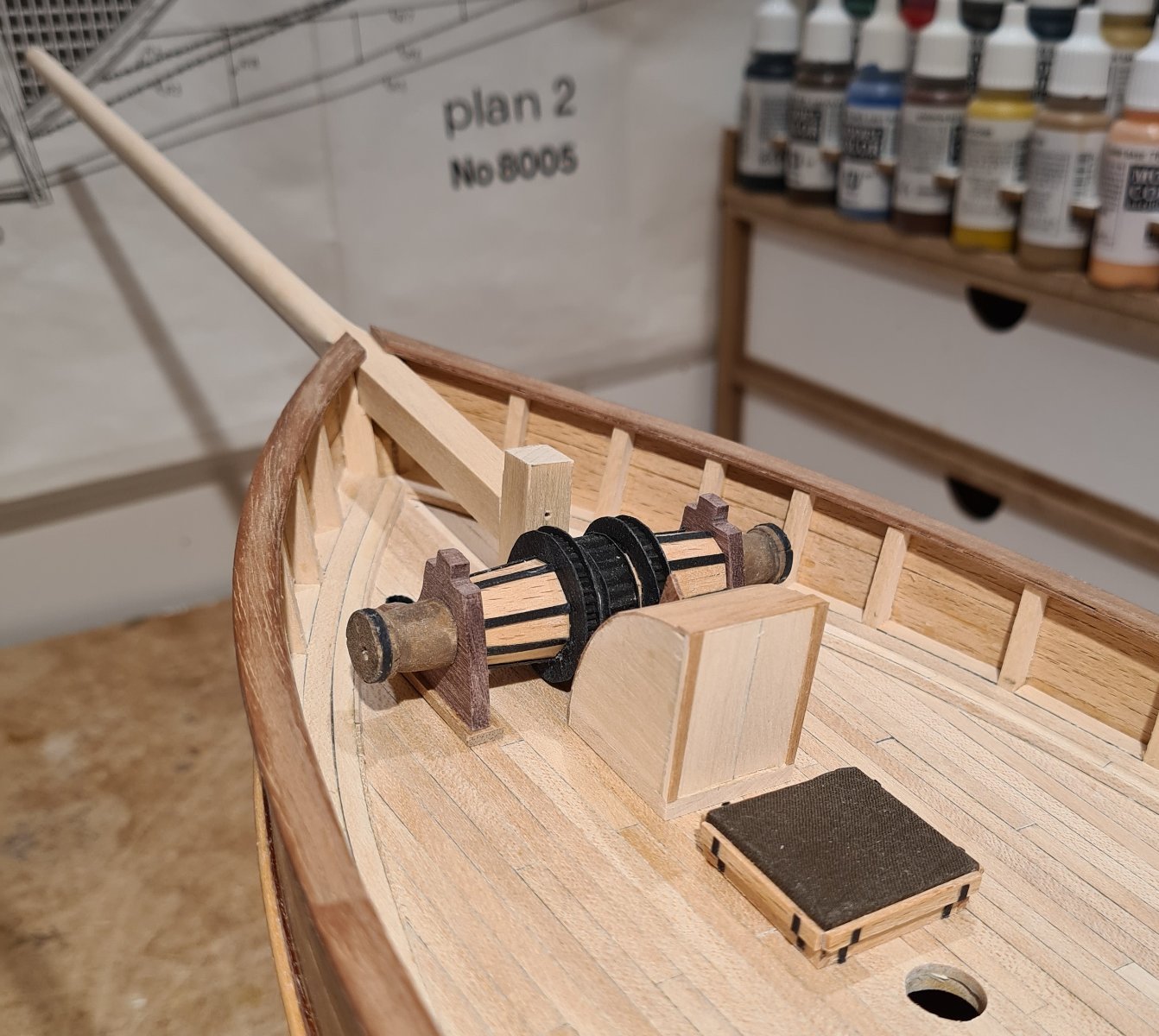
For the windlass, the kit contained some nicely made brass pieces.
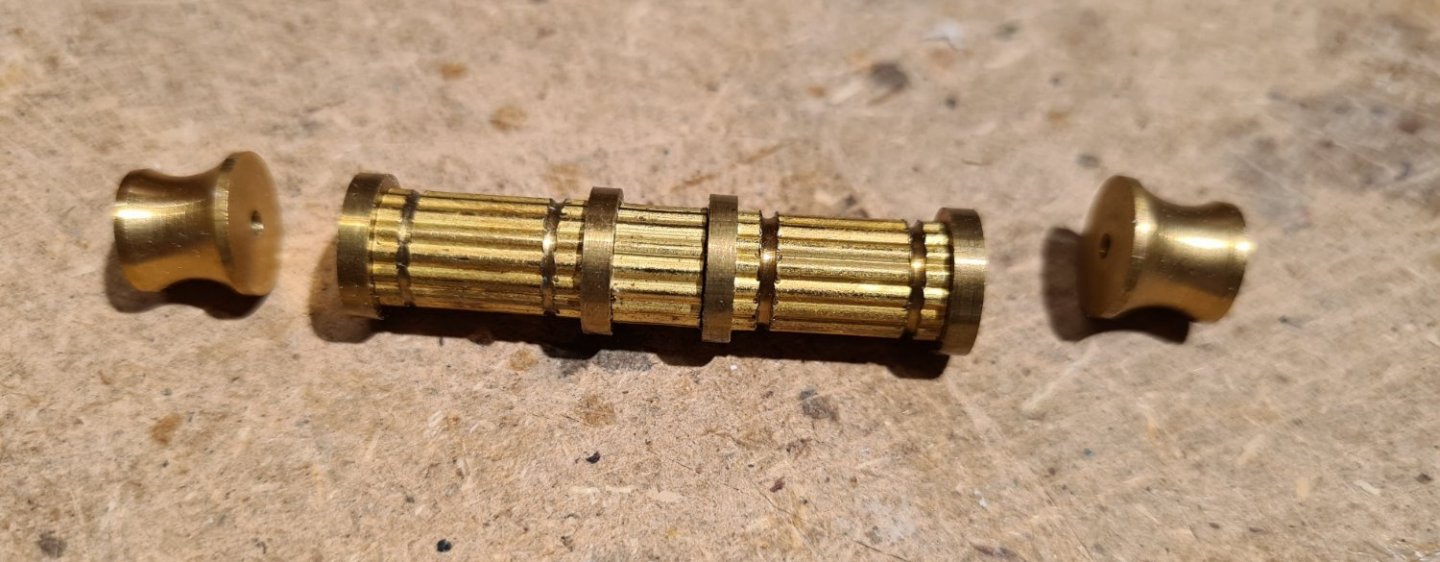
However, I don't feel that the roll is accurate enough. So I decided to make my own pieces.
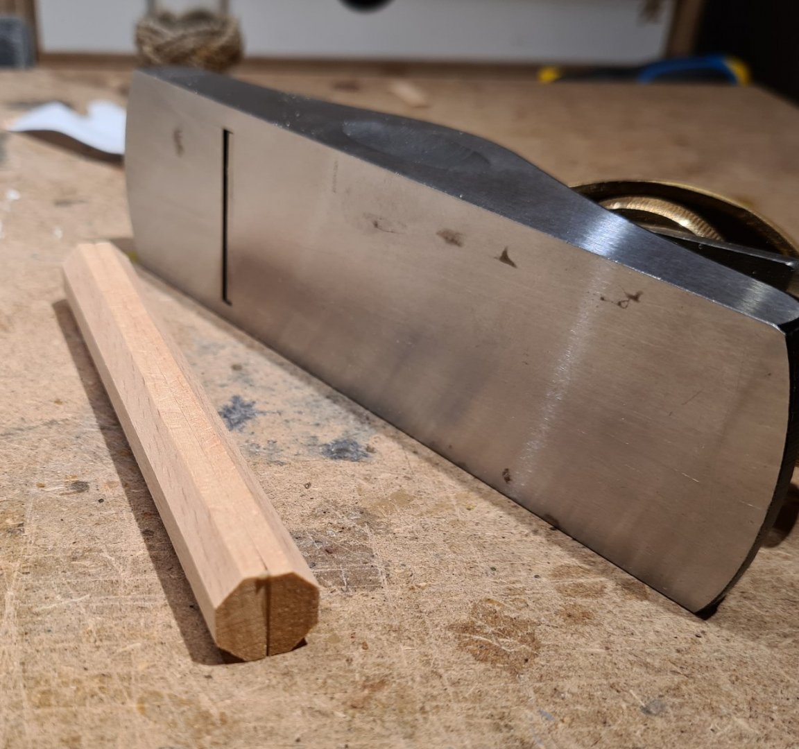

The result, thus far. There are still the handles, and the mechanism for turning the drum to install. Maybe I will wait with that for later, so I won't break them when working with other things.

I'm still thinking about redoing the windlass drum. It may be a bit too big. I will look at how it looks together with the rest and decide later...

-
The trip to the Netherlands was very fun and interesting. However, it turned out to also gift me with a sample of the Coronavirus. The security queues at Schiphol airport on the way home were far from orderly, and quite long. I think that was where I caught it. As I'm vaccinated, the sickness wasn't too bad, and while recuperating I have been able to continue forward with the next installation on the deck.
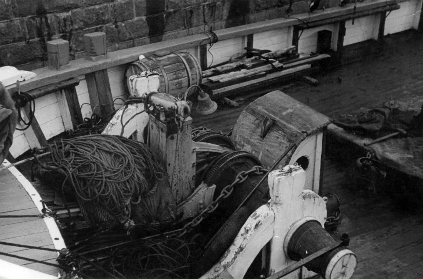
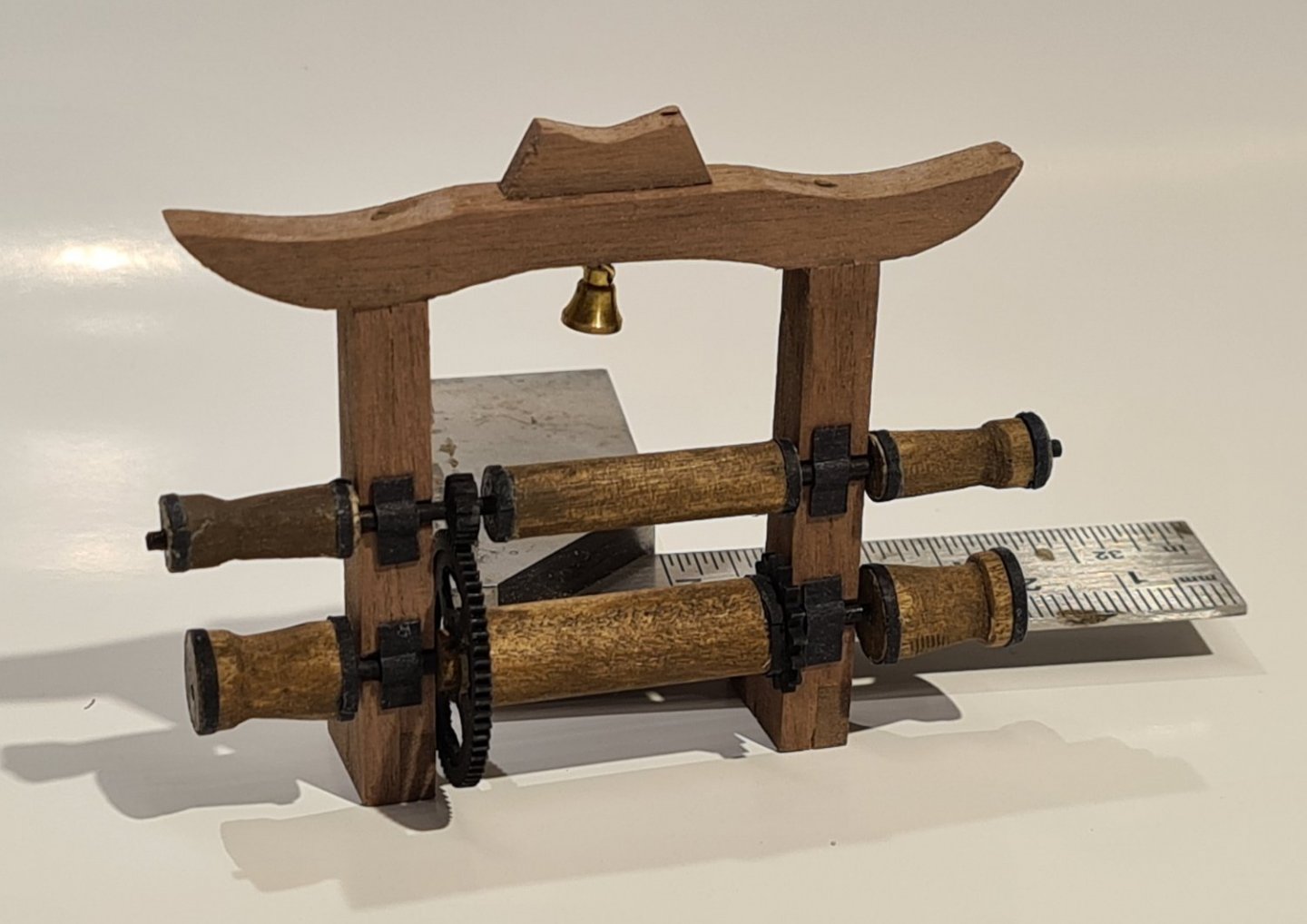
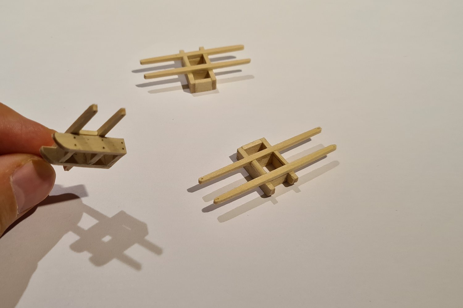
In the photo below, there is a construction just fore of the main mast that the boom and gaff are resting on.
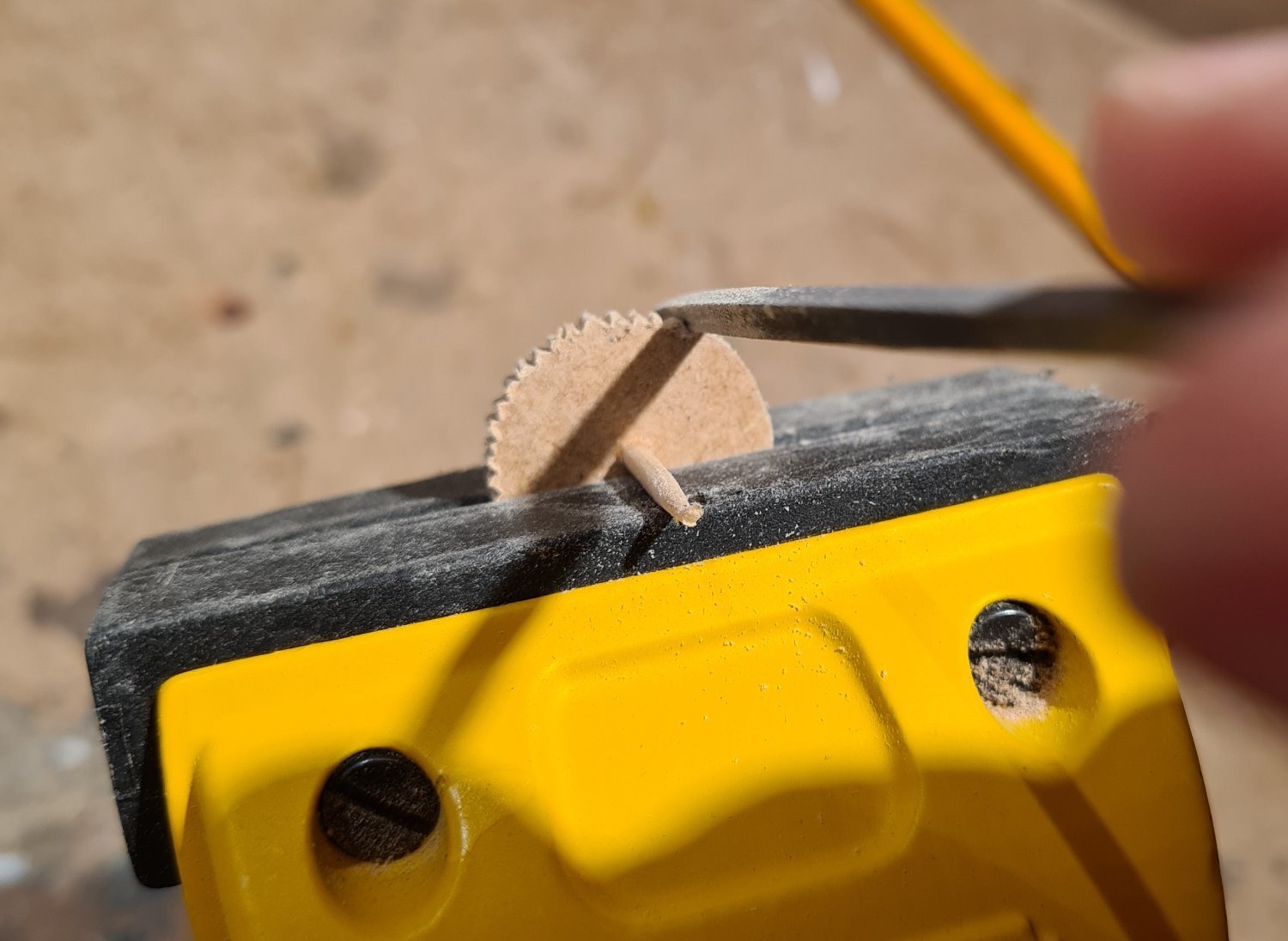
I interpret that as a winch of the following type. (The photo is from the 50 year older brig Gerda of Gefle, but I think it could serve as a prototype.)
I salvaged some cogwheels from a broken timer.
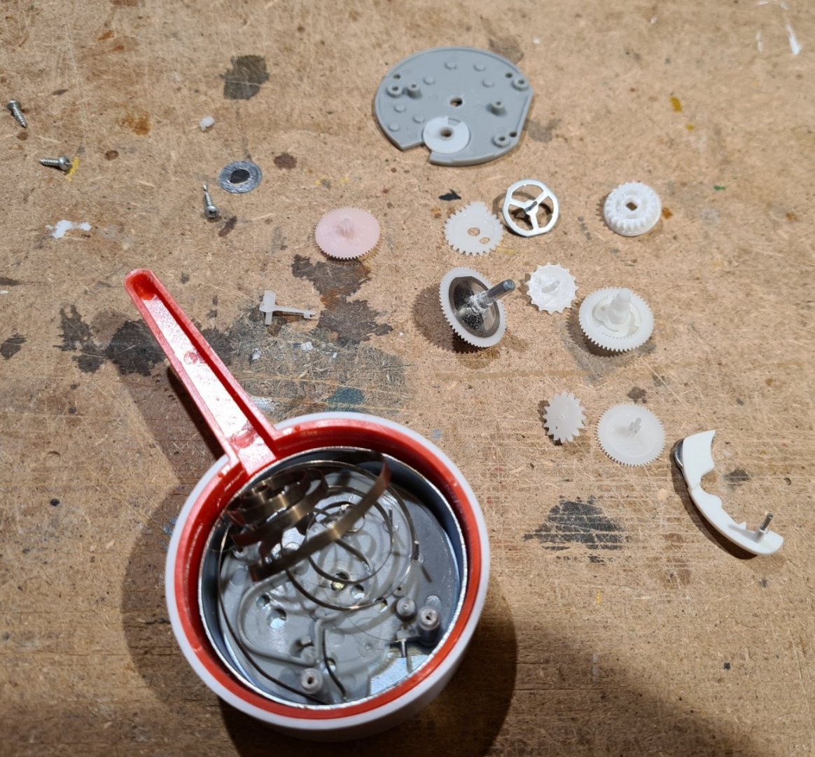
The final result does not quite work. For that, I think I would have needed some better precision tools, like a lathe.
-
The progress of this build has been slower the last couple of weeks. Other things have come in between, such as a trip to the Netherlands with the "Friends of the Vasa museum". It was four very interesting days, with visits to several museums and other maritime themed places (including the Rotterdam harbor).
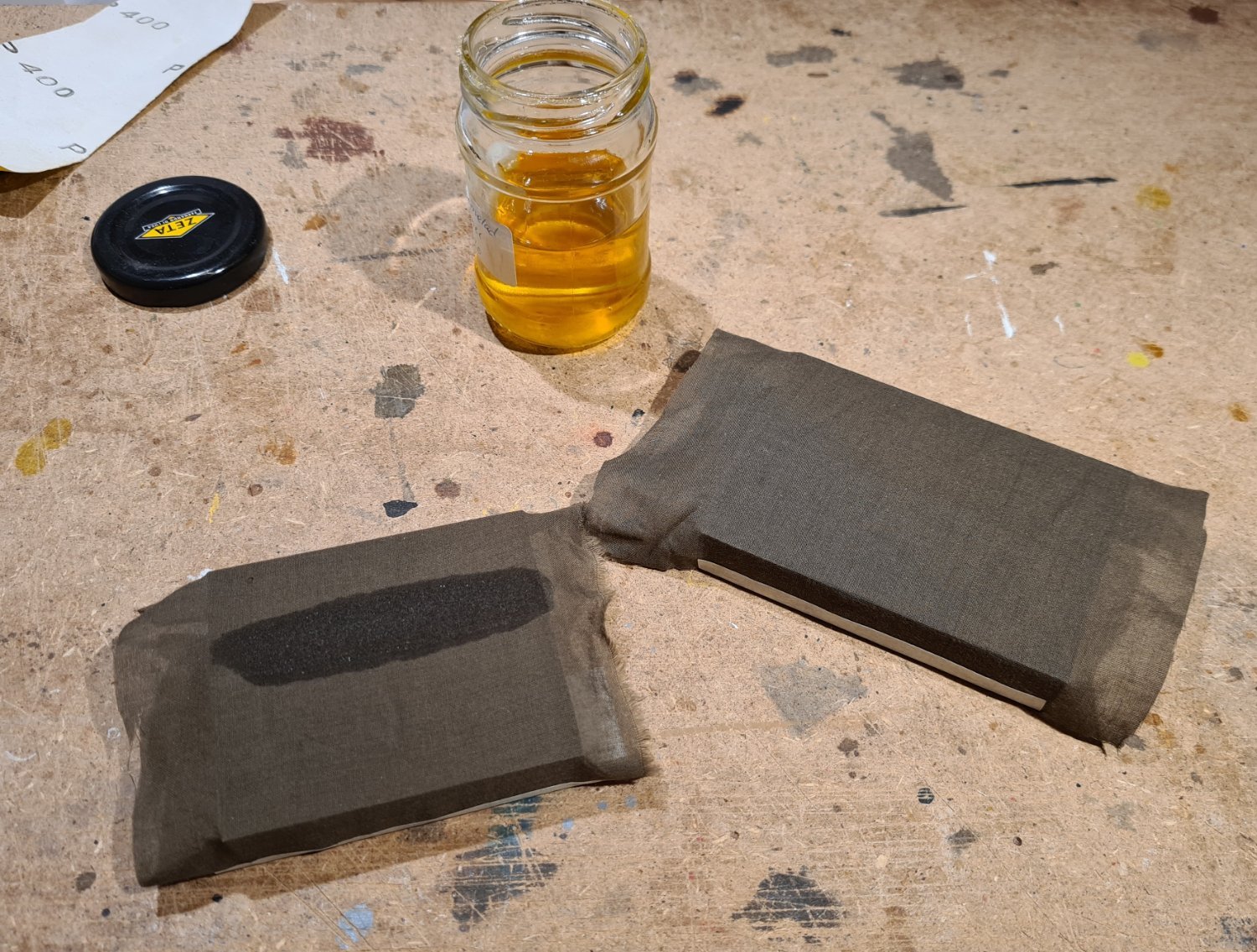
Back home, I have finished the hatches.
The top is covered in thin dark olive colored cloth, which has been soaked with two coats of shellac.

The metal clamps are made from thick paper, and glued in place.
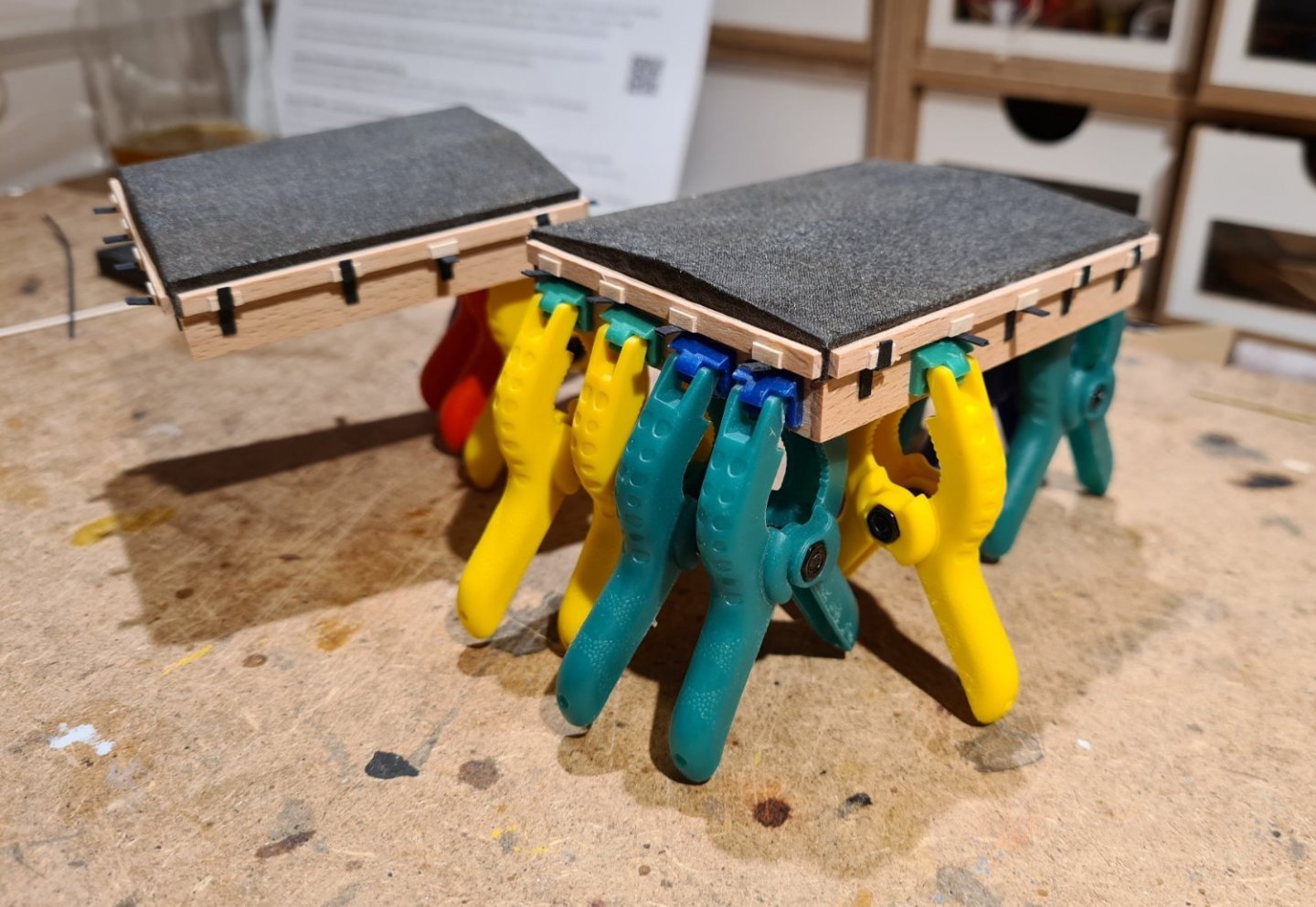
And the finished result.

-
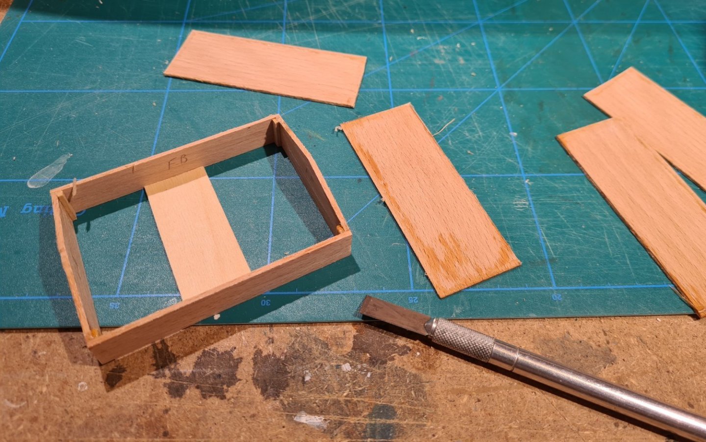
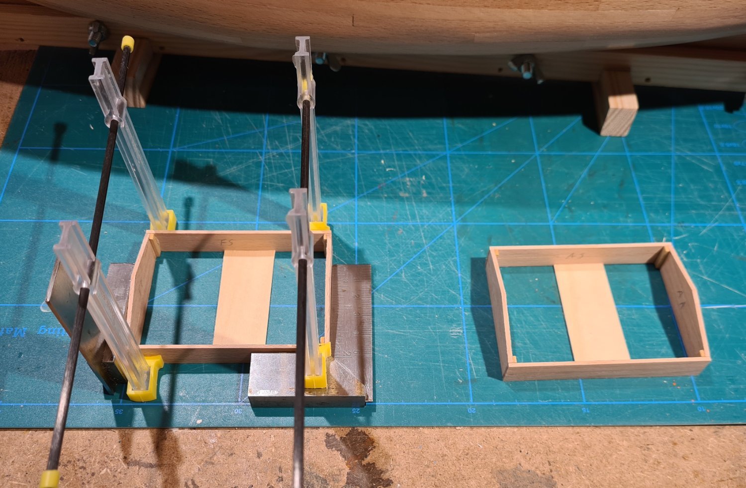
I continue with the buildings and fittings on the deck. Next are the hatches. I made the guess that the original hatches had about the same area as the deck houses that were added later. This also fits what can be seen over the railing in later photos. I have also found a plan for a similar ship (although slightly longer) that gives the hatches as 11'7" by 8' English feet. This measurement correspond well with the other sources, so that is what I decided on. The height of the coaming I also estimated from photos of similar ships.
I built the hatches as separate assemblies.

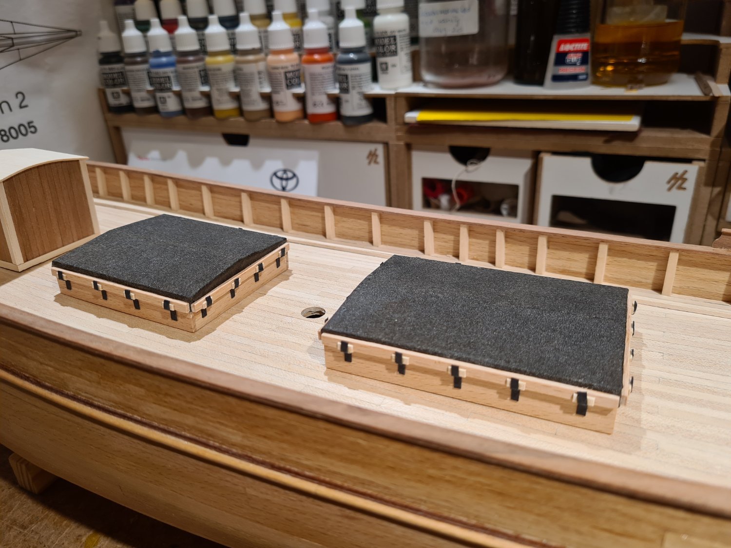
When I tried them in place and compared with other sources, the angle looked to be a bit steep. The forward hatch also looked to be a bit long. There was not enough room to place the winch between it and the main mast.

So I disassembled the hatches using alcohol. Then reduced the angle and shortened the forward hatch.
The hatches will be covered with tarp. So there is a bit more to do before they are finished. My reasoning is that, since I plan to present the ship with sails, the hatches should be covered. No captain would leave harbor in the Baltic without securing the cargo.
- Keith Black, clearway, Peanut6 and 3 others
-
6
-
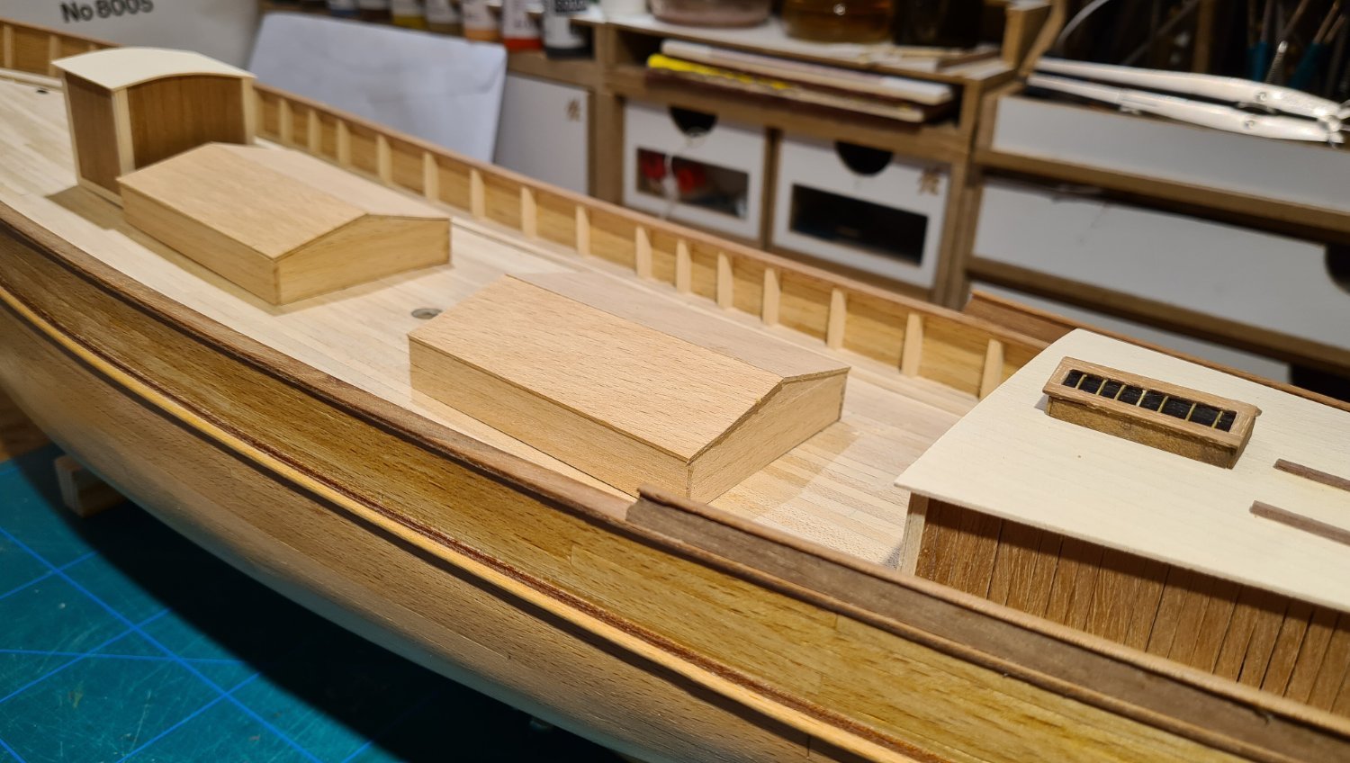
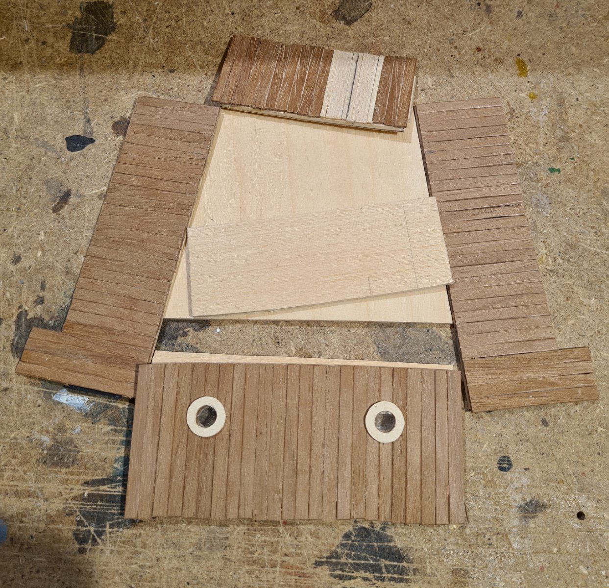
The cabin has gotten a skylight. A little project in itself.
I have also made a box to cover the steering geer. It has the dimensions from the kits plans. The plans places the wheel on tha aft end of the cabin. However I think that that is a later arrangement. This fits better with the photos I have. I have also found a model at the maritime museum I Stockholm that has this configuration.
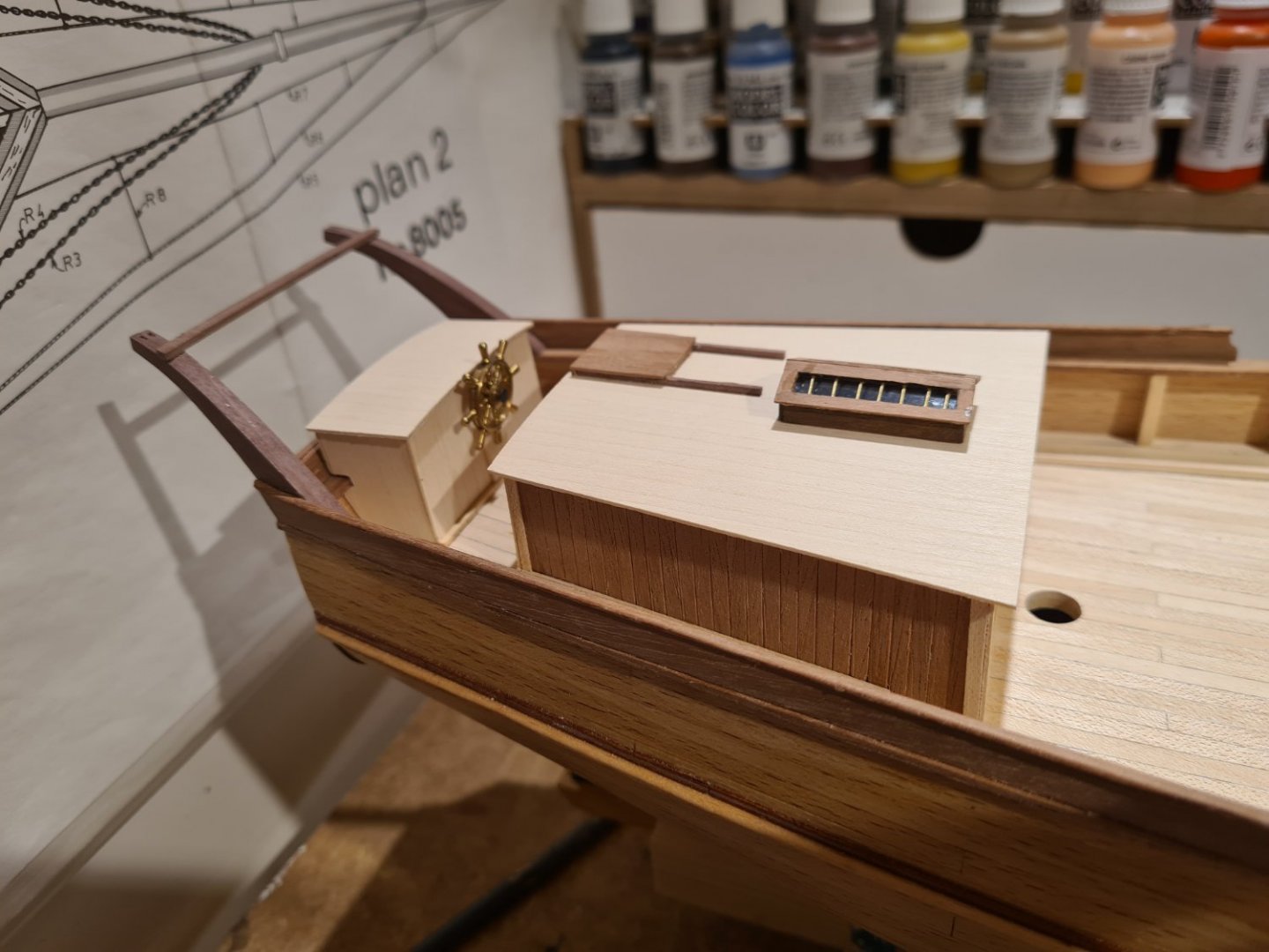
The wheel is actually from the kit, and it looks really good. In the picture it is only temporarily attached, as is the whole box. I will add it permanently when I attach the rudder.
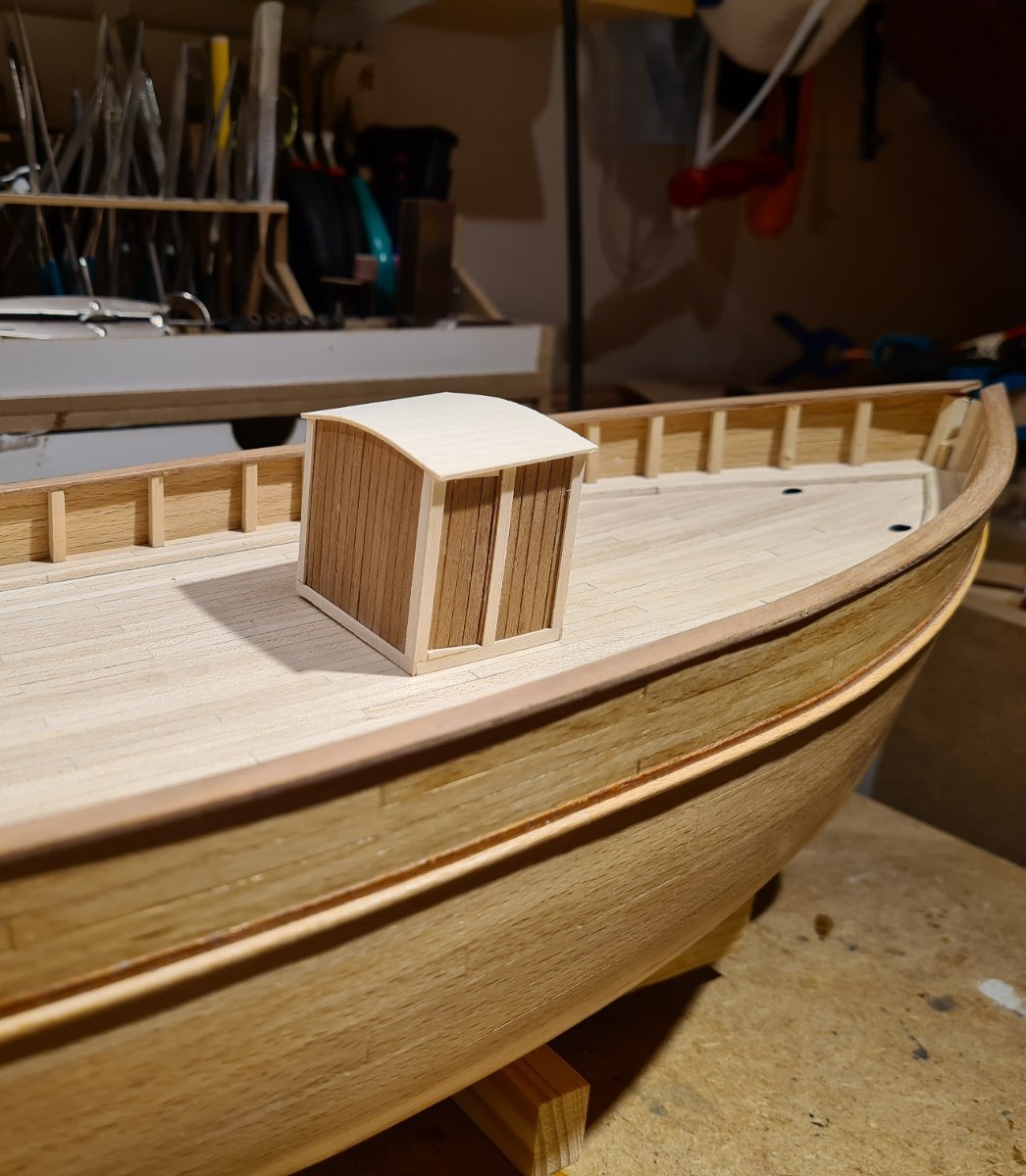
I have also made a small deck house, as seen on the historic pictures.

-
Even more benefits of a detailed build log then😀 Maybe you can blaze a trail for others to follow. Looking forward to see what you will do with it.
-
God start with your first build! Good luck.
In my experience it is the heat that makes the wood pliable much more than the water. I usually have a thermos of hot water to dip the strips in. Half a minute is usually enough.
- mark.bukovich and mester03
-
2
-


Meta by bolin - Billing Boats - 1:40 - original fore-and-aft schooner rig
in - Kit build logs for subjects built from 1901 - Present Day
Posted
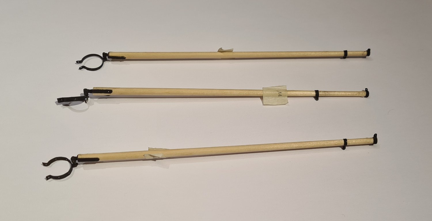
Finally I'm back again. A 50th year anniversary and a lengthy business trip later I'm now back with a small update. This time it's the bowsprit.
With that I can start assembling the deck equipment and the rest of the individual parts. I hope that it won't take as long with that...