

bolin
-
Posts
479 -
Joined
-
Last visited
Content Type
Profiles
Forums
Gallery
Events
Posts posted by bolin
-
-
Actually, I was working on the stern and transom. The deck was a bit of distraction.
Now I have returned my focus aft.
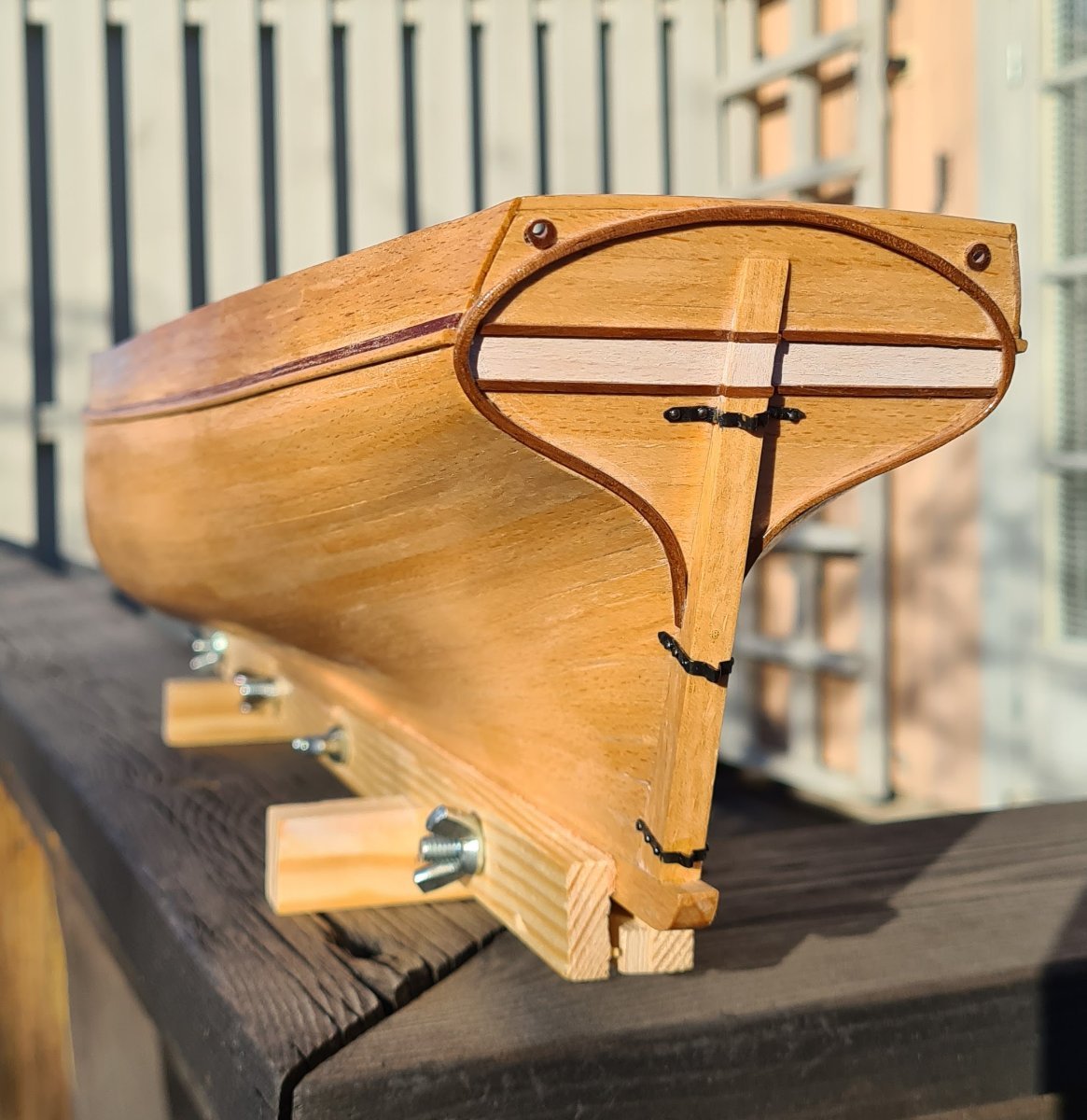
The transom has received a whitewashed field just above the waterline. The real ship had a similar field in natural wood color. As I don't plan to paint the hull, I wanted another color scheme that gave a similar impression.

I have also made a rudder, and hinges from brass.
The hull has finally received two coats of shellac.
-
I cannot say that I'm an expert in this area in any way, but I might offer a clue. I checked the book Hand, Reef and Steer by Tom Cunliffe. On the topic of hard weather sailing, he mentions the unbending of the sail and even replacing the gaff with a shorter one for a specially made try sail. Maybe the sail was actually partly unbent from the mainmast to lower the gaff for reefing?
Just my thoughts...
-
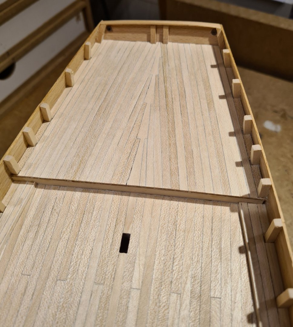
Well, the aft deck was a bit of play time. Most of it will be covered by the cabin. The joggled planks was just for testing out how to do it. However, I believe that the cabin is of the type that leave an even walk way along it’s sides. I have seen several photos and models that seem to show that the planks follow the bulwarks. The angle of the planks aft of the cabin I cannot explain by anything else than artist’s expression.
- Keith Black, Wintergreen and yvesvidal
-
 3
3
-
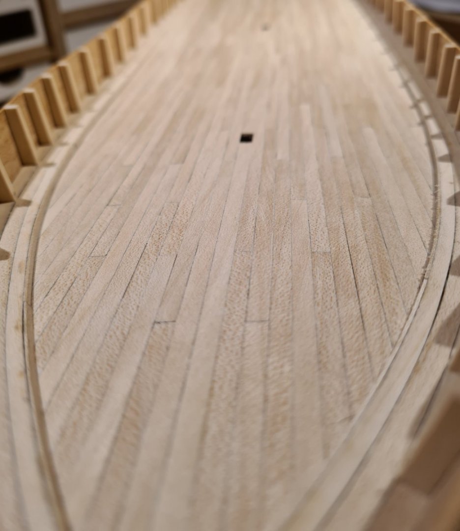
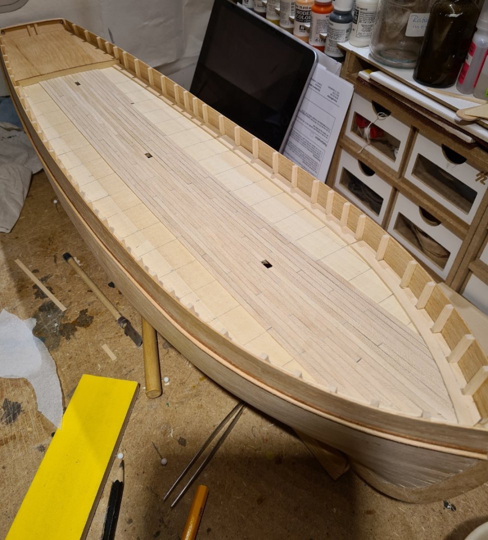
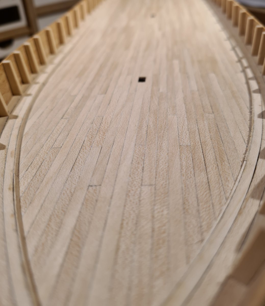
...and tonight I put in the last planks along the sides of the deck. When looking at the photos, I see that there is still some minor cleaning up to do. But otherwise, the deck is done.
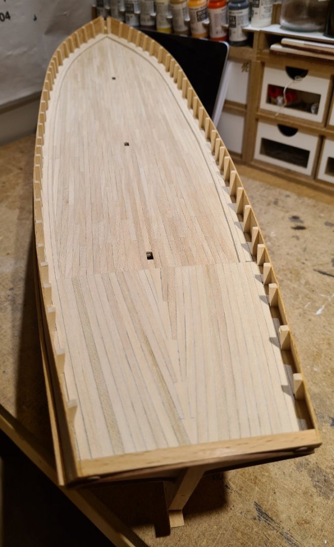
I elected to plank the full deck, even though there will be hatches, a deck house and an aft cabin. I hope that it made it easier to get a smooth and even surface. The king plank and the planks joggled into will be mostly covered. I made it mostly for fun.
- Wintergreen, Keith Black, clearway and 2 others
-
5
-
I have started planking the deck. For this I have bought a 0.5 mm maple sheet, to replace the kit's precut deck that I have already discarded. I don't know the real dimensions of the deck planks, but from the blueprint I posted earlier (from another vessel) and photos of similar schooners, I think that 150 mm is about right. So, I have ripped planks using a knife and a steel ruler that are slightly narrower than 4 mm. This method requires that plank edges are sanded to get a smooth edge, so they end up about the correct width.
Before installing, I use a soft pencil along the edges to simulate caulking.
-
I have built three models with shell-first (or plank-first if you will) method. See my signature for links. They have all been built upside down over moulds. This ensures the shape of the hull. When lifted of the mould the hull shapes where all surprisingly stable.
However, these where not my absolutely first models. I would consider the method slightly harder than building frames first.
- AnchorClanker and mtaylor
-
2
-
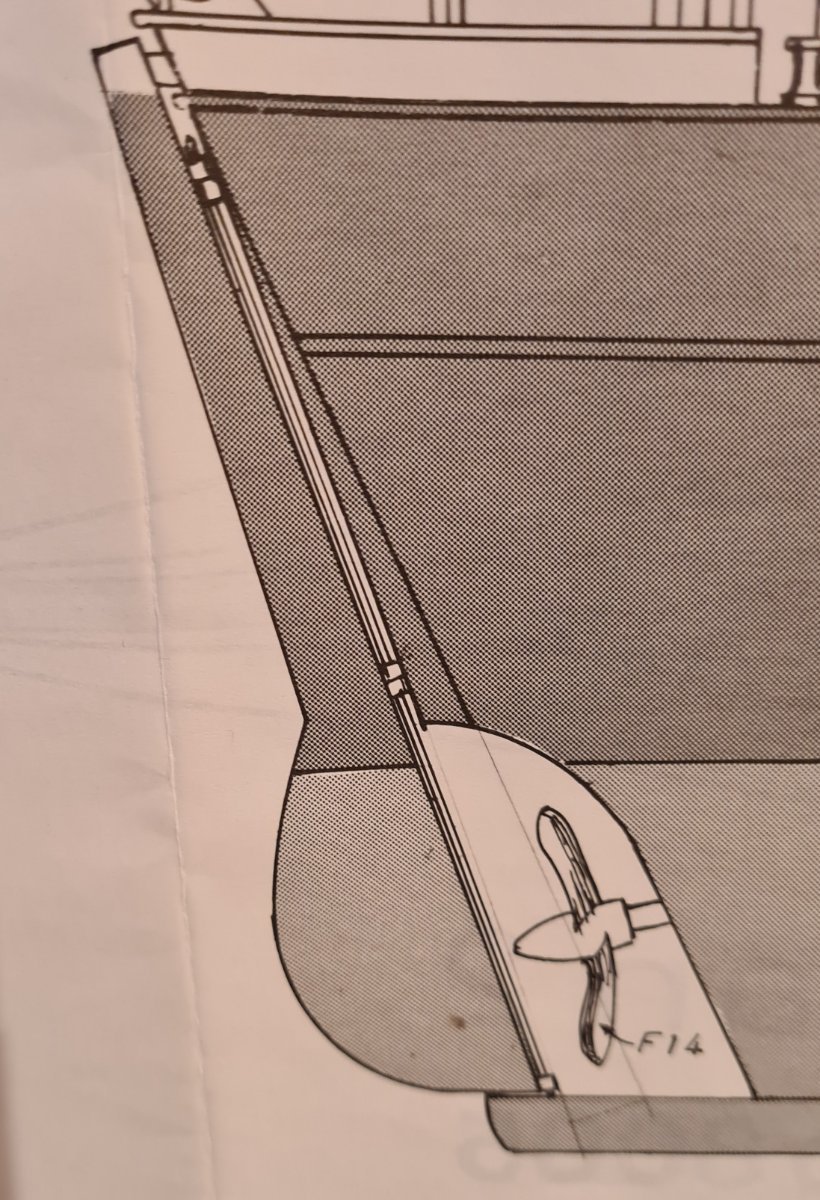
I have focused a bit on the stern. As I have already described, I have filled in the cut-out for the propeller. There are a few other things that I think I need to modify compared to the kit.
The plan does not show typical pintles and iron bands, instead there seem to be a rod running through a series of sockets.
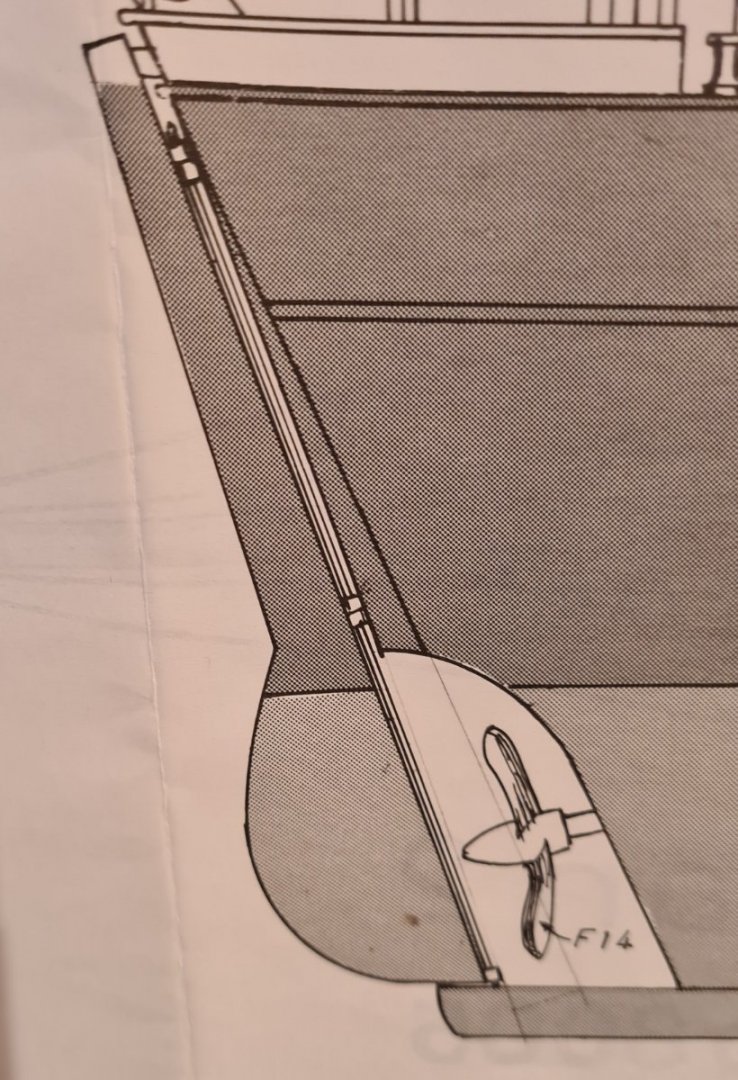
I have found some pictures that indicate a similar construction. However, I suspect that this might be a change made after the installation of a motor and propeller. I will go with a more traditional mounting of the rudder. The picture below shows the typical coloring and decoration of the transom of these schooners. Meta was no exception.
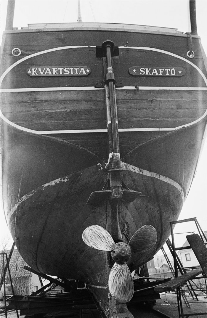
As I did with the white line on the side, I will however make the white border in wood of another color.
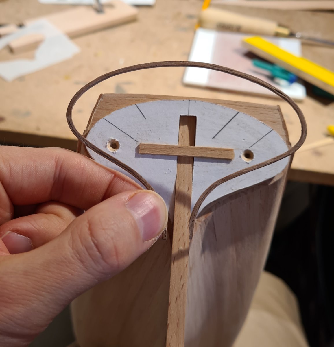
First I made a jig. I use 1 mm walnut for this. They were soaked for a half a minute in hot water, and then put in the jig to dry.
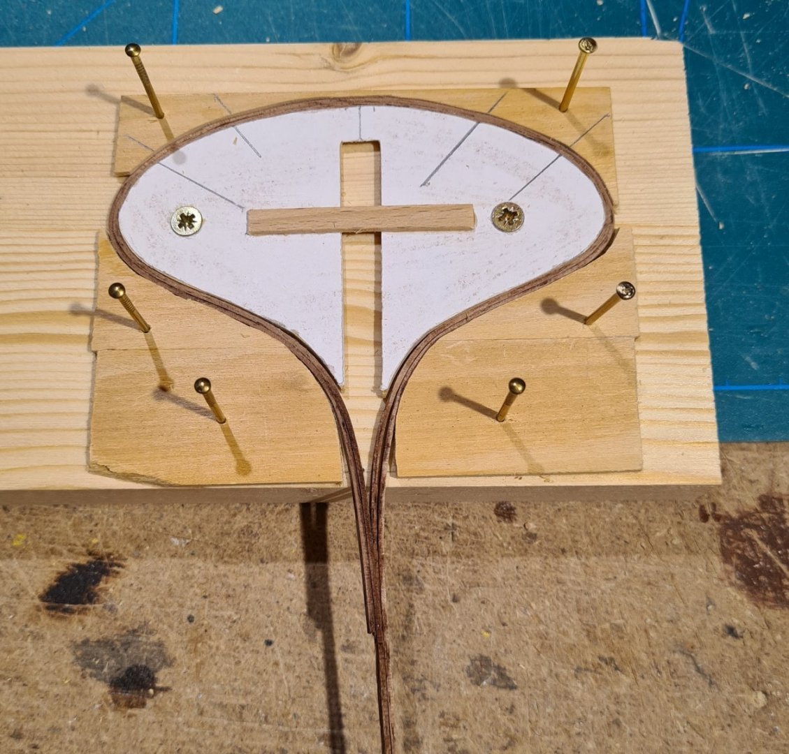
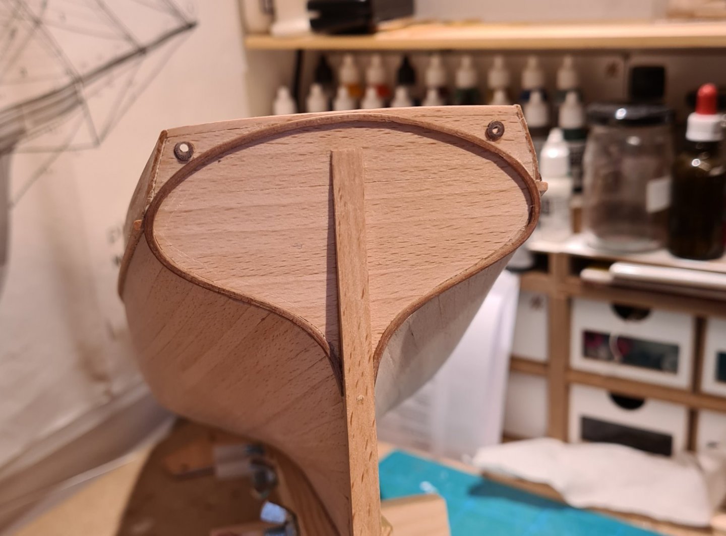
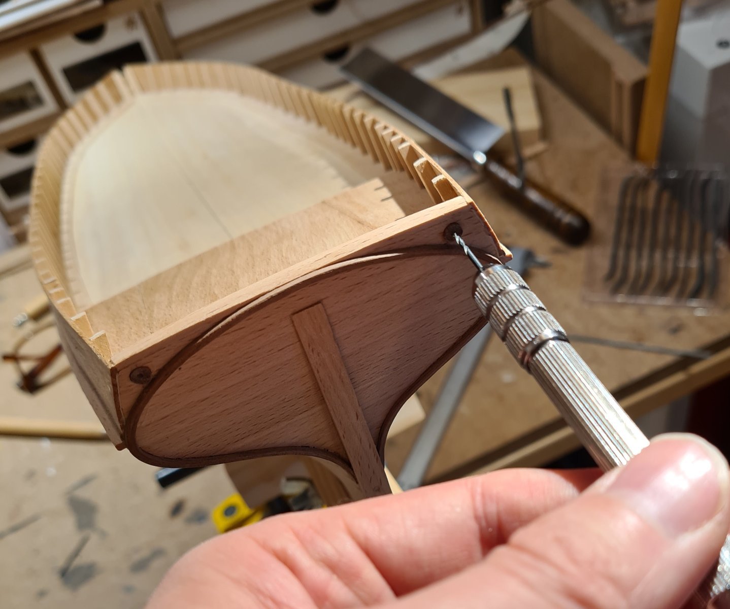
The two holes for mooring lines in the transom were made by drilling a larger hole, in which a 4 mm walnut dowel was inserted. Then the real hole could be drilled in its center.

-
My thoughts are that, since you have already done the NRG half hull model, you might try something more than than a launch or similar. The challenge you may encounter on a larger hull is the lining off and planning of the planking that a smaller hull may not present. Maybe a kit is not what you are looking for? And maybe not a warship? I have recently planked a early twentieth century schooner hull. No frills, just a big body to plank. It gave lots of practice.
- Ryland Craze, Ken_2, Canute and 2 others
-
5
-
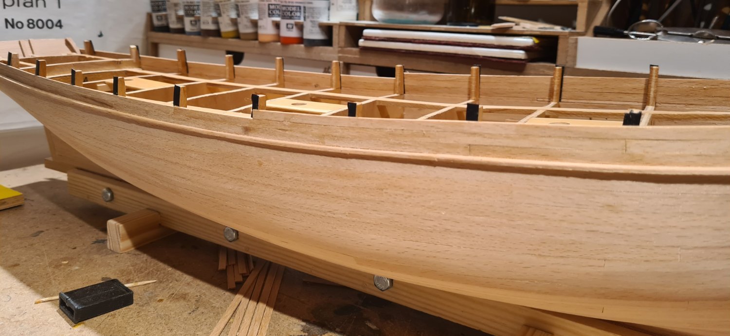
The bulwark is now completely planked. I have added a strip of mahogany as a contrast color in place of the painted white stripe on the original. This wood was actually part of the content of the kit. The first of the kit material that I have actually added to the model. Otherwise, I have only cut things away and replaced them. 😄
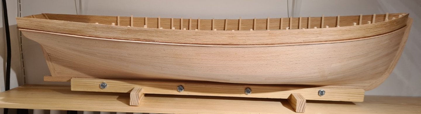
I have also installed the false deck. The kit supplied deck had warped and cracked, so I didn't want to use that. I only used it as template and made a new from lime wood.
The bulwark supports are also from lime. Since I don't have a detailed plan, I made an educated guess about dimensions and spacing. They are closer together along where the shrouds will be attached.
- Peanut6, Wintergreen, Keith Black and 5 others
-
8
-
-
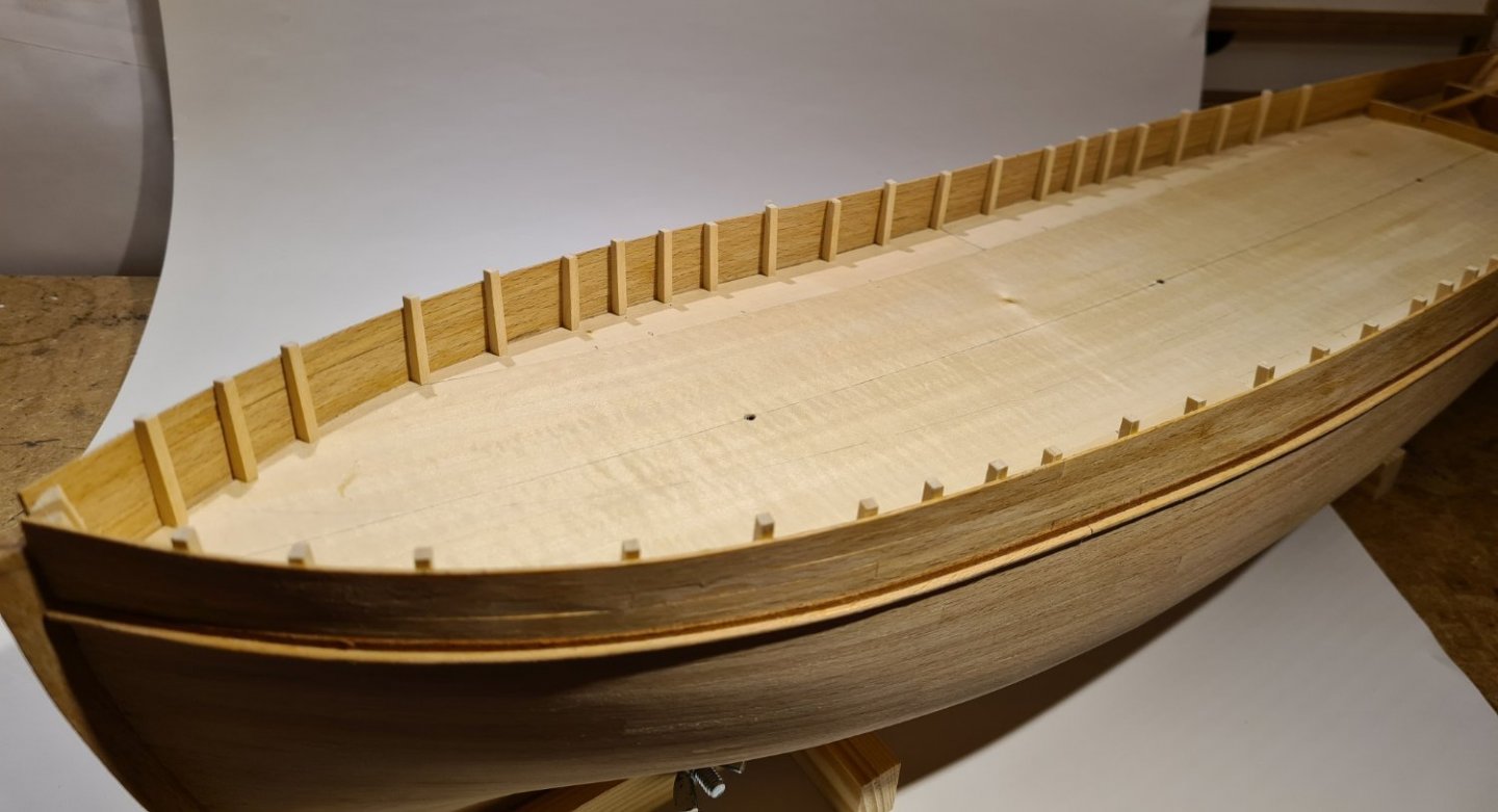
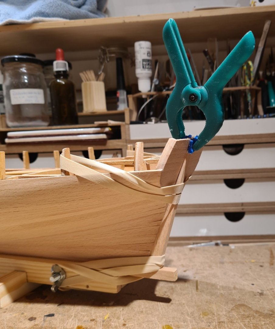
I have worked on planking the bulwarks. Based on some educated guesses, general dimensions from for example the cross-section plan I showed earlier, and photos, I decided on 1mm thick and 4 mm wide planks.
First, I added the "outside" of the waterways, which protrudes a bit from the hull side. The bulwark stanchions from the bulkhead prevent adding the plank properly.
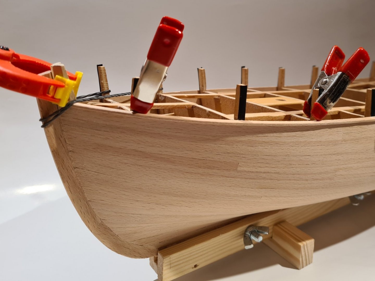
Since I will replace the plywood stanchions from the bulkheads, I put tape to prevent glue from sticking.

And now the last plank is installed.

- Keith Black, Wintergreen, clearway and 4 others
-
5
-
 2
2
-
The next step is to start with the bulwark. From here on, I will more or less leave the kit and its instruction. Most of the upper structures were changed during the ship's life, until the shape that is represented in the kit. So I need to do my own research. This post will mostly be for me to think through and confirm that my deductions are sound.
The following picture is the best close-up I have, and I will come back to it for many details.
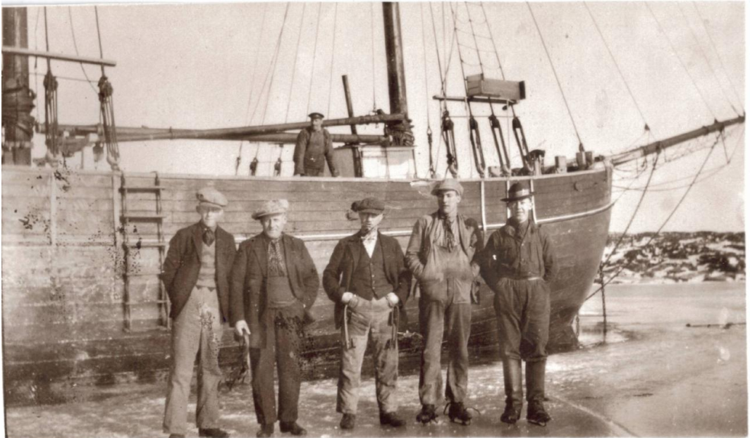
Regarding the bulwark, I find two details in this picture. First, at the bow, it looks like the bulwark is not as thick as the hull planking. Second, the man standing on the deck looks to be standing on something. If the deck was level with the white line, he would have very long legs.
I have the following plan (from https://digitaltmuseum.se/011024765524/ritning) for a cross-section of another ship from the Baltic Sea of about the same size and period.
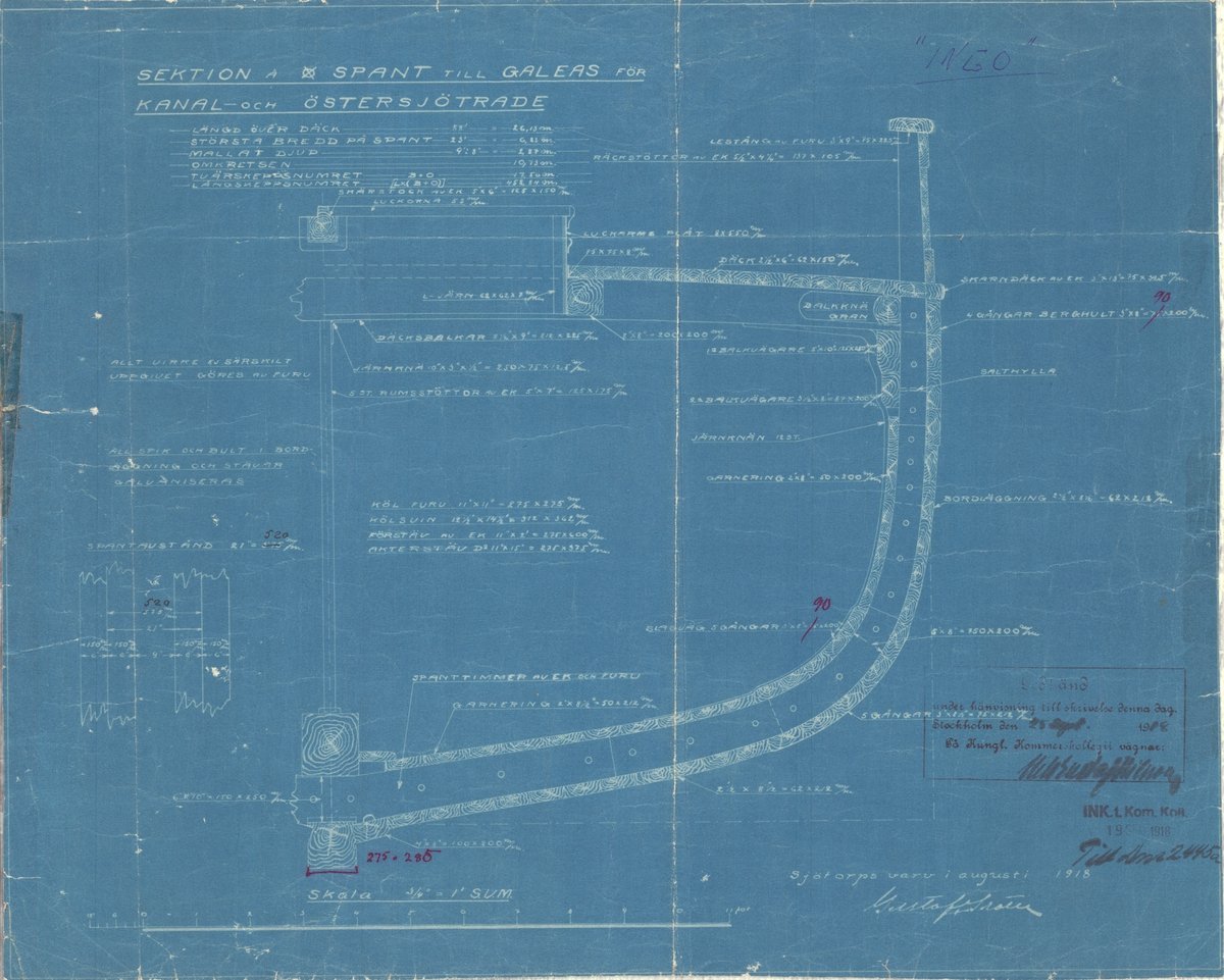
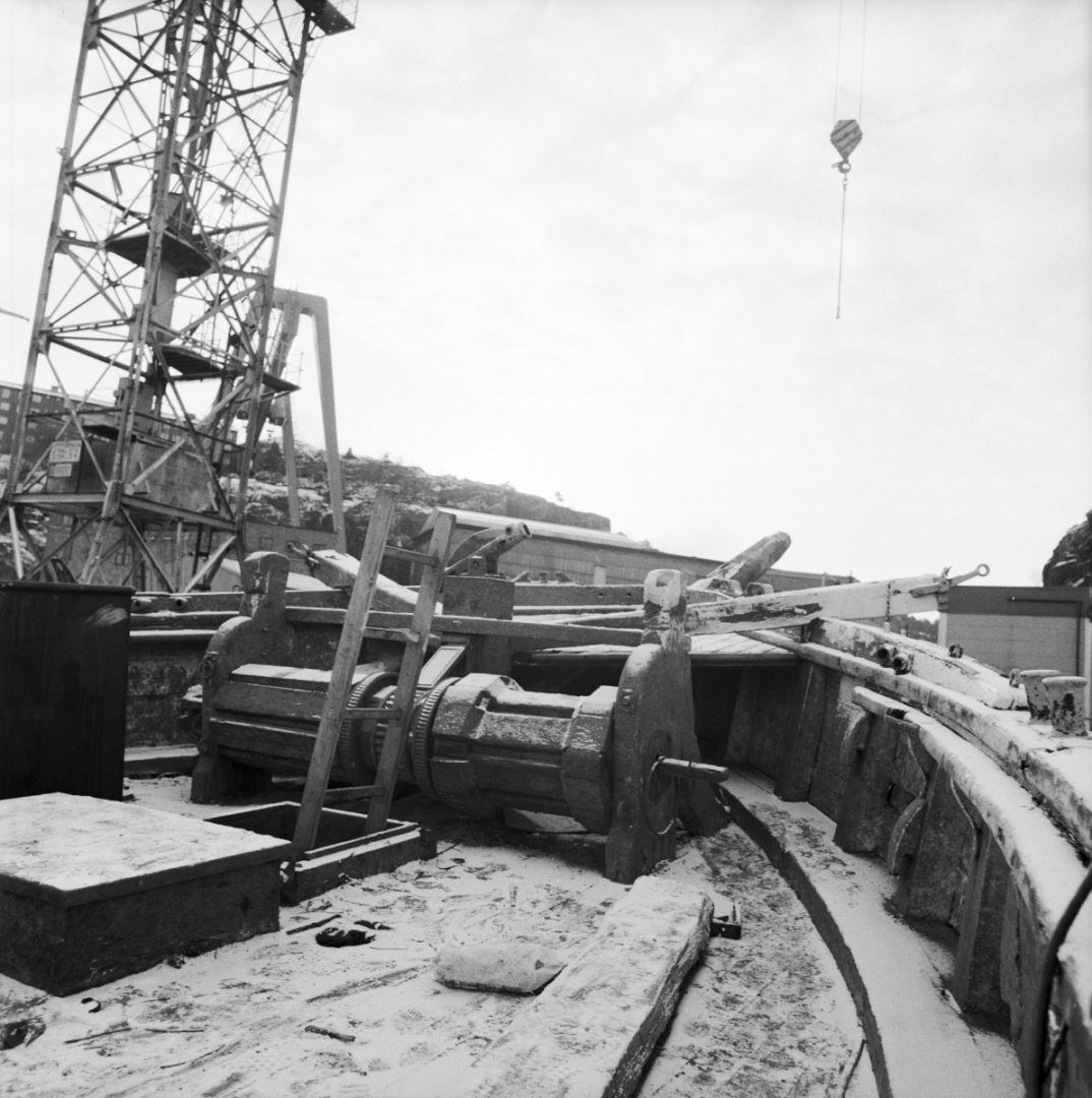
However, I don't think it is representative of how Meta was built. On many pictures of schooners from the same time as Meta it looks that the waterways are very thick and wide. As in the following picture, of yet another ship, from about the same time. This would explain the height of the man in the picture, so I think it likely the Meta looked the same.
I don't know why they were constructed like that. Maybe they had the same purpose as wales, to strengthen the hull?
Cheers
Tobias
- Keith Black, clearway, Peanut6 and 2 others
-
5
-
On 1/27/2022 at 10:35 PM, Dave_E said:
Would one of the plank cutter tools be in order?
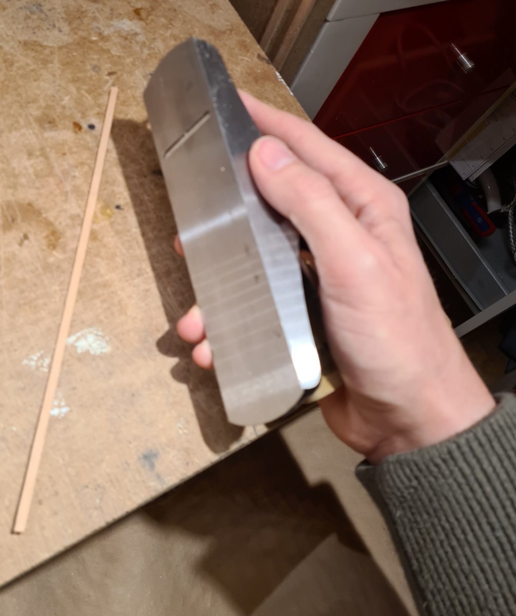
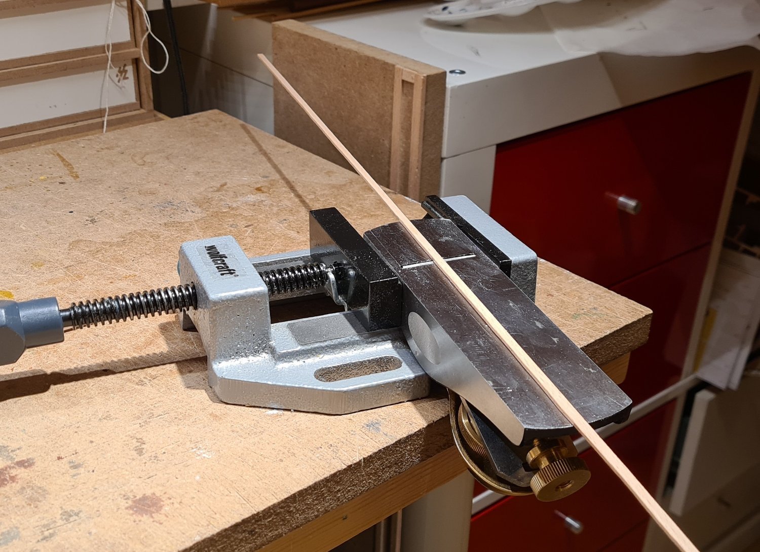
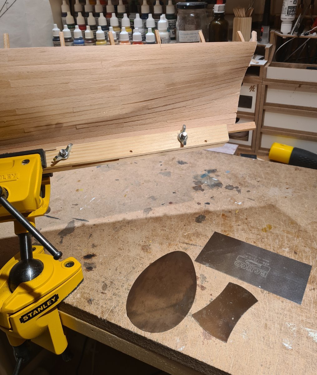
I mostly use a plane to shape the planks. It gives much sharper edges than sandpaper, and much better control than a knife. Knifes tend to follow the grain of the wood.
I hold the plane in one hand, and drag the plank with the other.
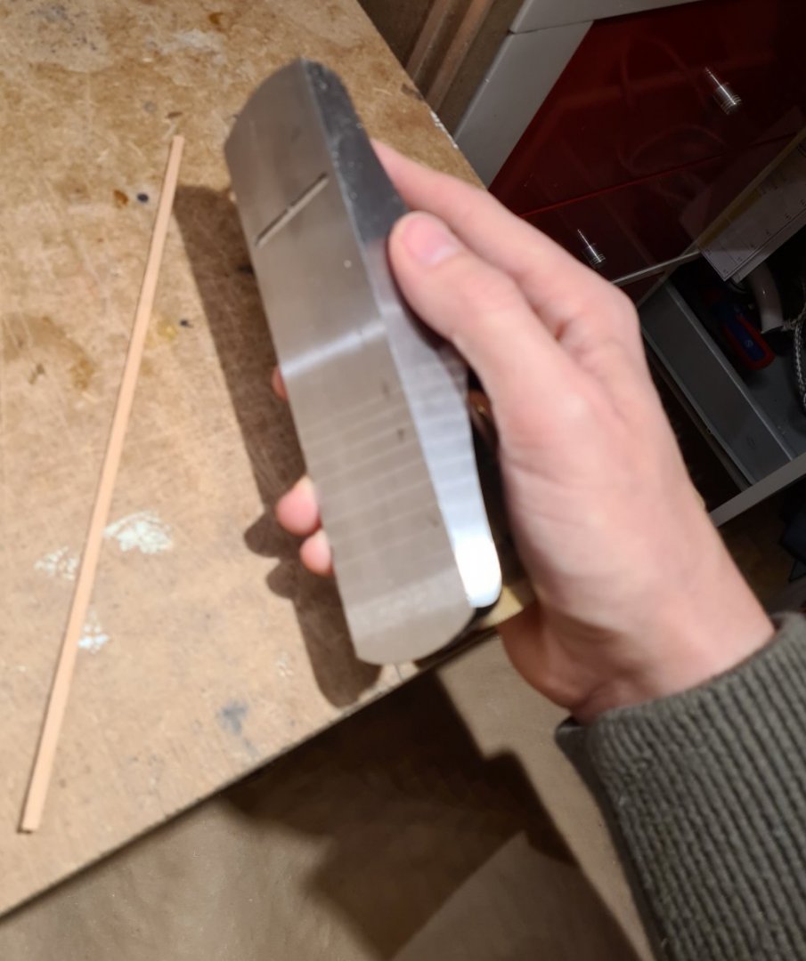
I recently learned a new trick, place the plane in a wise. Then you can use both hands to control the plank. Especially useful for bevelling.

-
Thanks Keith and Håkan.
Yes the camera lens is sometimes a more discerning observer than your own eye. The field of psychology likely has an explanation for that… I just find it curious.
-
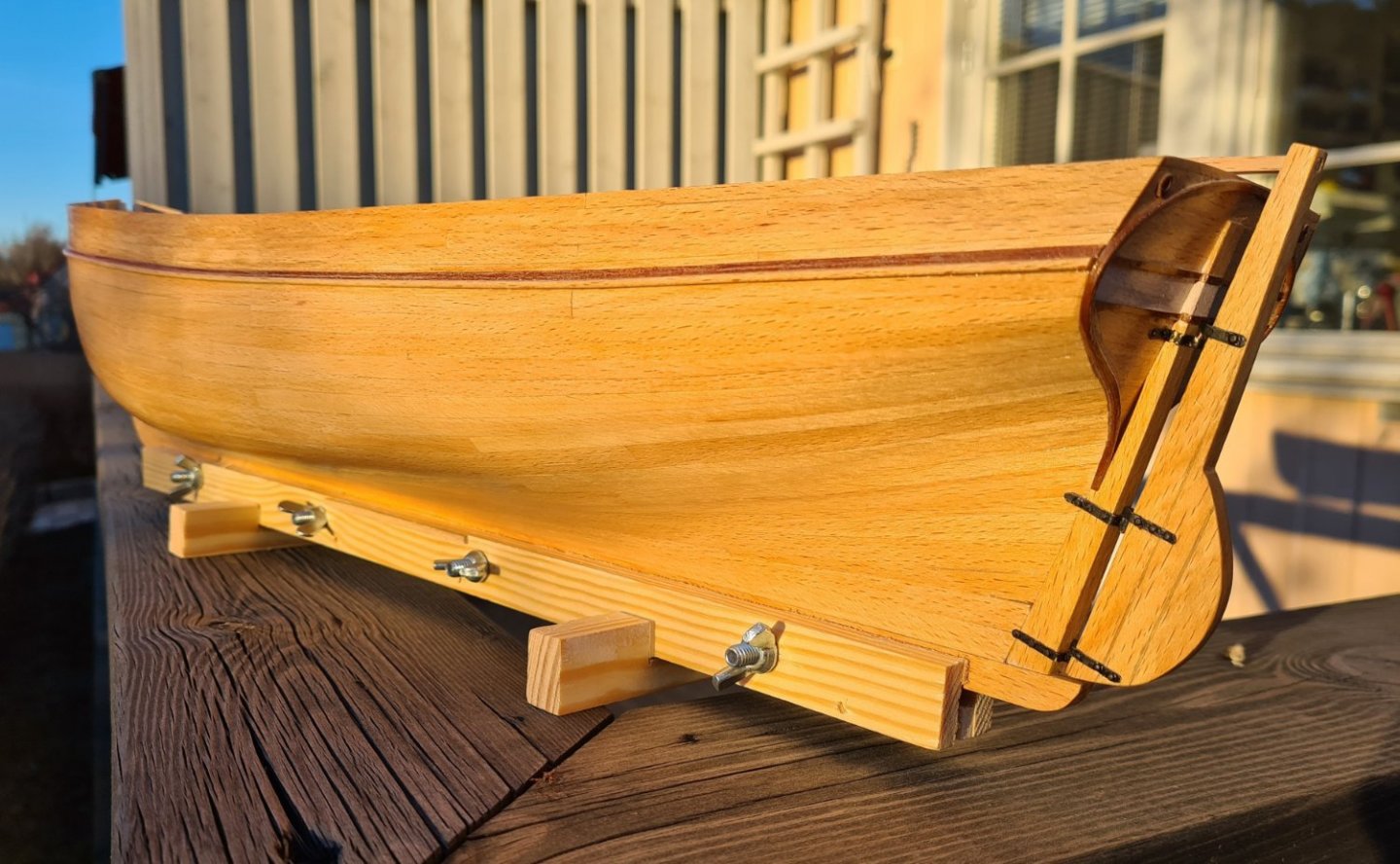
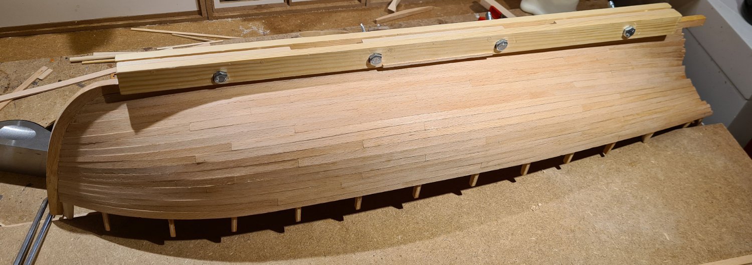
Today I have been busy scarping the hull. On the picture below, the different types of scrapers I have are shown. For this purpose, I think that scrapers are quicker and more precise to work with than sandpaper. Of course, you need to sharpen them quite often.
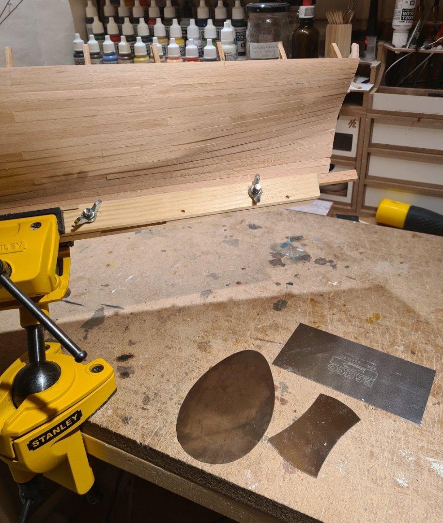
The result thus far
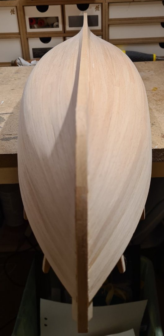
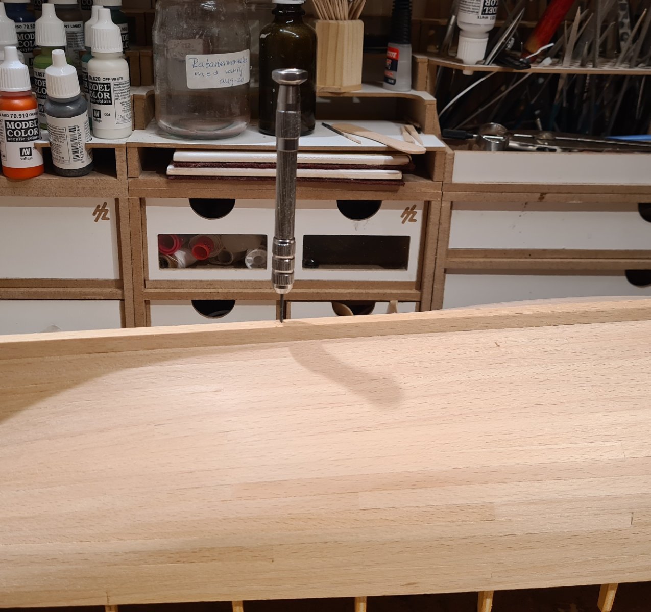
I also remembered to drill holes for the stand now, while I can still handle the hull upside down. I plan to use the same type of mounting as I did on my medieval longship, a cradle in plexiglass with a central brass pin that fits into small holes in the keel.

And finally the stem piece is glued in place. Now that I look at the photo, I see that there is a bit of more cleaning up to do of the planks.
-
My choice to use shorter planks is primarily to have them in scale length. There are very few trees that give planks that are 25 m long 😉 I have not been overly pedantic about the length of the planks, a few may be slightly over long. But as Toni Levine mentions in The Ship Modeler's Ten Step Program workshop, "nothing says kit build as much as end to end planks". I wanted, at least, the impression of realistic plank length and butt shift pattern.
In a way, it is also easier to fit the planks when they are shorter. It might take longer, but I think it's easier to avoid mistakes and gaps with shorter planks. You also don't need to add glue to the full length of a long plank and get stressed by adding clamps along all the length before the glue starts to set up. (I'm using PVA glue, not superglue.)
The kit came with full length strips for planks, and no instructions on more realistic plank lengths. I have replaced the wood in the kit and researched planking techniques from various sources.
- Wintergreen, Nirvana, Keith Black and 1 other
-
4
-
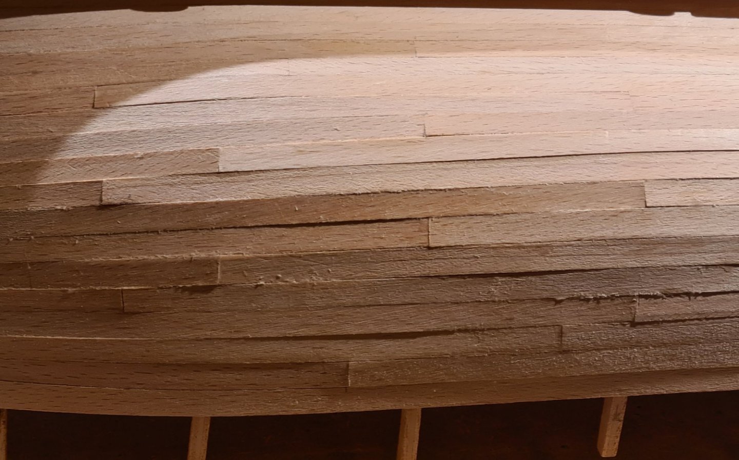
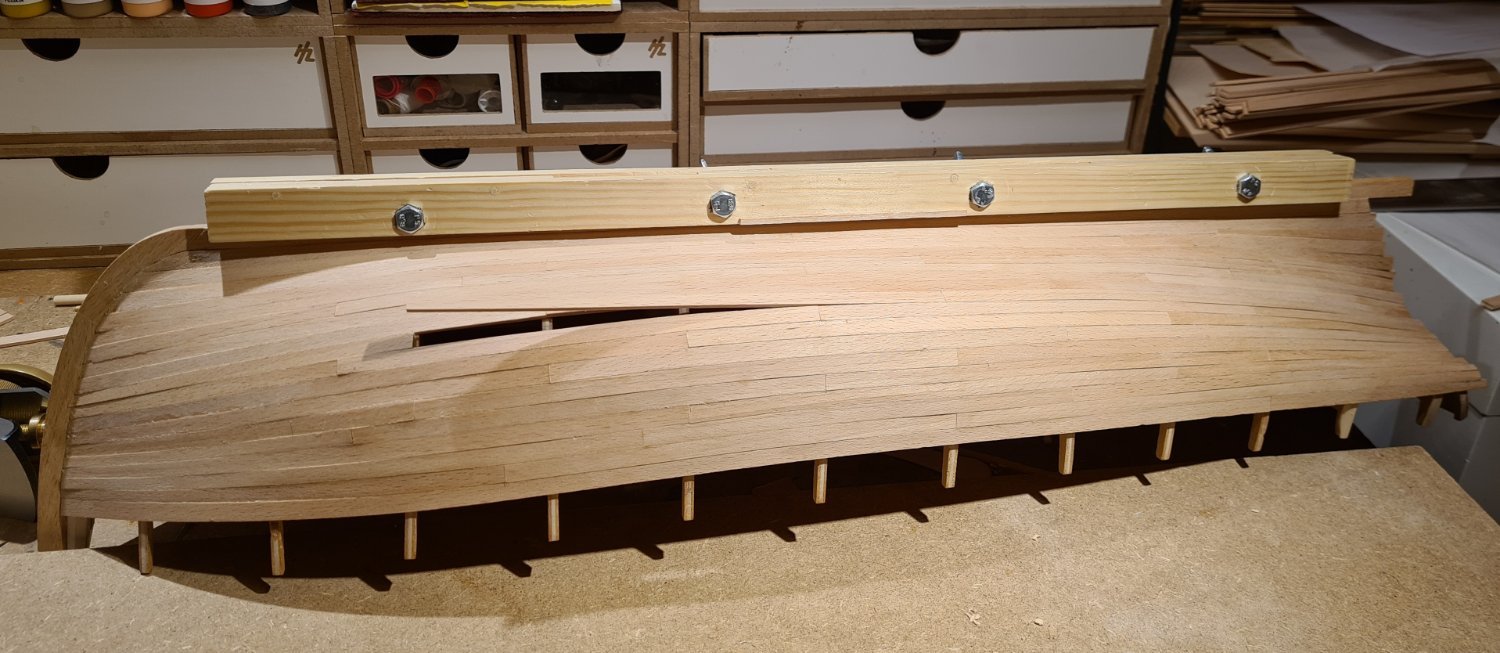
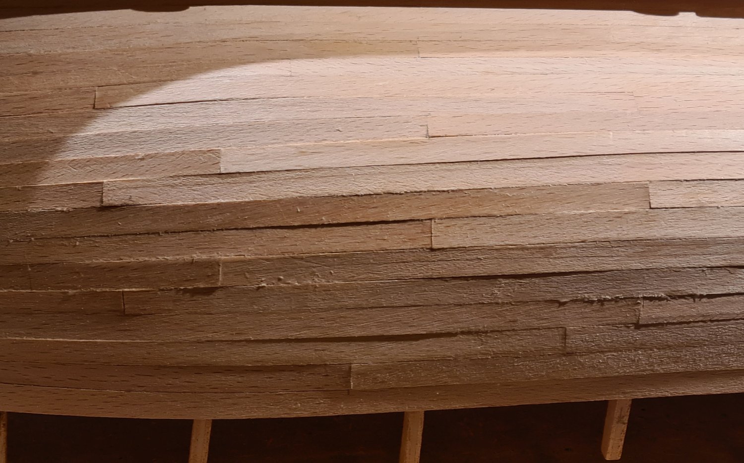
Finally! Actually a bit earlier than I had expected, the last plank is installed. The progress of the planking has been good, and I have been able to put a bit more time into building than I thought.

There is still a bit of cleaning up to do. Some of the scarf joints has sticks out a bit. But overall I'm satisfied with the result. The picture below shows the worst part in the worst side light.

- Keith Black, Peanut6, clearway and 4 others
-
7
-
You are welcome to join Håkan. Thanks for reminding me about Vaddocs build 😀
-
-
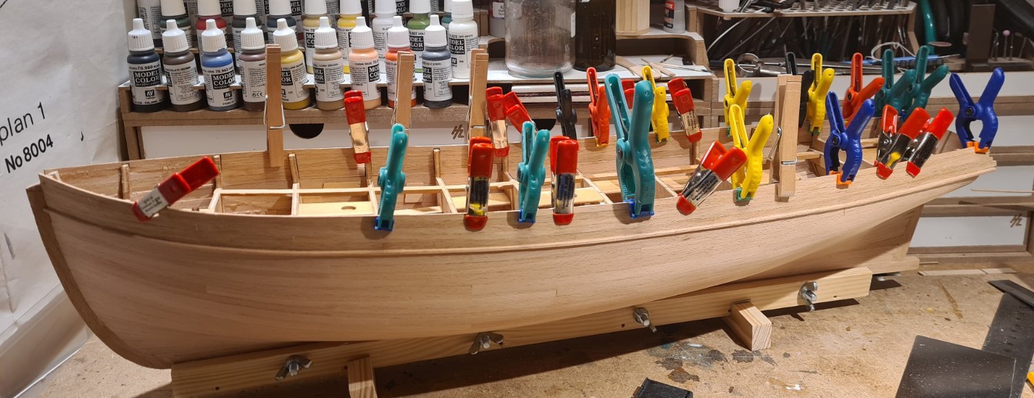
Each plank is a small project in itself:
- cut plank to length,
- measure the with at each bulkhead against the tick marks,
- use a plane to reduce the width of the plank,
- chamfer one edge,
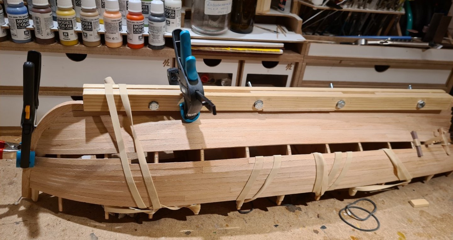
- edge bend to get the right fit,
- test out how to hold the plank using rubber bands, clamps etc.,
- add glue,
- clamp down,
- scrape off excess glue,
- repeat...
Now the end is in sight. Only a few evenings more...
- Peanut6, petervisser, clearway and 1 other
-
4
-
-
It looks very nice! I did not pay attention when you started your build log, but now I realize that this will be a rather big model.
-
I don’t have Monfelds book, so I can’t judge how it compares to my go to book, Harold Underhills Plank-on-frame models. It is a bit dated, and he does not describe the latest material or techniques. That is actually the books strength. He describe how to build a model using simple tools, many of which are home made. He wrote it just after the war when he had few tools available. This means that you learn the fundamentals, which can be simplified with access to better tools and materials. Such as modern glues.
- Jaager, EricWilliamMarshall, Canute and 1 other
-
4
-
Yet an interesting ship by you. I will pull up a chair and follow.
- mtaylor, druxey and Louie da fly
-
3


 Th
Th


Meta by bolin - Billing Boats - 1:40 - original fore-and-aft schooner rig
in - Kit build logs for subjects built from 1901 - Present Day
Posted
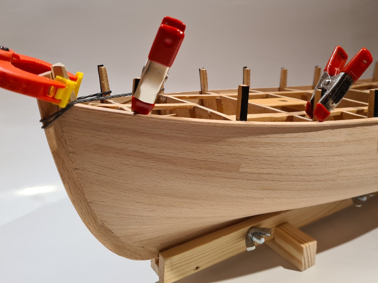
The next step is the top of the railing. I made a jig on the work table for getting the correct curve.
Then I edge bent two strips and glued them together on top of each other. In this way, the handrail would keep its shape even after I removed it from the jig.
After that, I needed to do the last things that required the hull to be turned upside down. That is to drill the hawseholes. The outside is lined with a disk of walnut.
The holes from the deck is lined with black paper.
With that out of the way, I could start adding things that will prevent me from easily invert the ship, like the davits in the aft.
Cheers