BANYAN
-
Posts
5,969 -
Joined
-
Last visited
Content Type
Profiles
Forums
Gallery
Events
Everything posted by BANYAN
-

cable laid vs rope (left vs right twist)
BANYAN replied to davec's topic in Masting, rigging and sails
Hi Jerry, actually it is the other way around -LH lay (S) lays up much stiffer and provides more strength and was generally used in standing rigging where strength was required (such as shrouds stays etc). However, it is not a hard and fast rule that LH lay rope was always used for shrouds etc; sometimes, shroud lay (4 strand) was used etc. RH lay being more flexible was generally used for running rigging. cheers Pat -
A nice looking build David, I have added you to my watch list cheers Pat
-
Thimble help needed
BANYAN replied to Senior ole salt's topic in Metal Work, Soldering and Metal Fittings
Hi S.o.s. - could you please advise exactly what part of the process is not working? If you find that the split tube sides are collapsing when bending, then you could try putting a bit of wire (same OD as the ID of the tube) into the channel as you bend it and that might help. If it is that you cannot obtain/bend a circle around the pliers perhaps a temporary jig using an old/broken drill bit of the appropriate OD, set into a wood offcut (secured to the bench or a vice), around which to form the ring might assist - similar to making wire rings. These two ideas can work together as a combination as I have used them successfully but I was using copper not aluminium. I hope this helps? Pat -
Hi Rod, thanks for looking in mate. I have brushed it on as I go; usually to the individual parts. I am contemplating a final all over spray as some recommend but I am still researching what long-term effects this may have on the rigging (worried it may go brittle with age). I will need to mask or avoid the finely detailed items and faux glass etc in the stern windows. I am also concerned that the white paint may yellow a bit with age with a coating of dull coat. cheers Pat
-
You may call it slow progress John, but this is positively flying compared to my build Look forward to seeing the update. cheers Pat
-
ROYAL CAROLINE 1749 by Doris - 1:40 - CARD
BANYAN replied to DORIS's topic in - Build logs for subjects built 1501 - 1750
I'm just waiting for one of the figurines to come to life; they certainly look real enough! cheers Pat- 883 replies
-
- 4
-

-
- royal caroline
- ship of the line
- (and 1 more)
-
Neat idea for the jig Danny, they have come out very good indeed. cheers Pat
-
Beautiful work as usual Alex - I think you are right with the half-open door, looks quite good and provides the sense of individual parts, not a single/solid panel. cheers Pat
-
Looking the 'ants pants' mate! cheers Pat
- 803 replies
-
- 2
-
-
- colonial cutter
- modellers shipyard
- (and 1 more)
-
Mate for a first effort that is an absolutely terrific finish you have achieved. cheers Pat
-
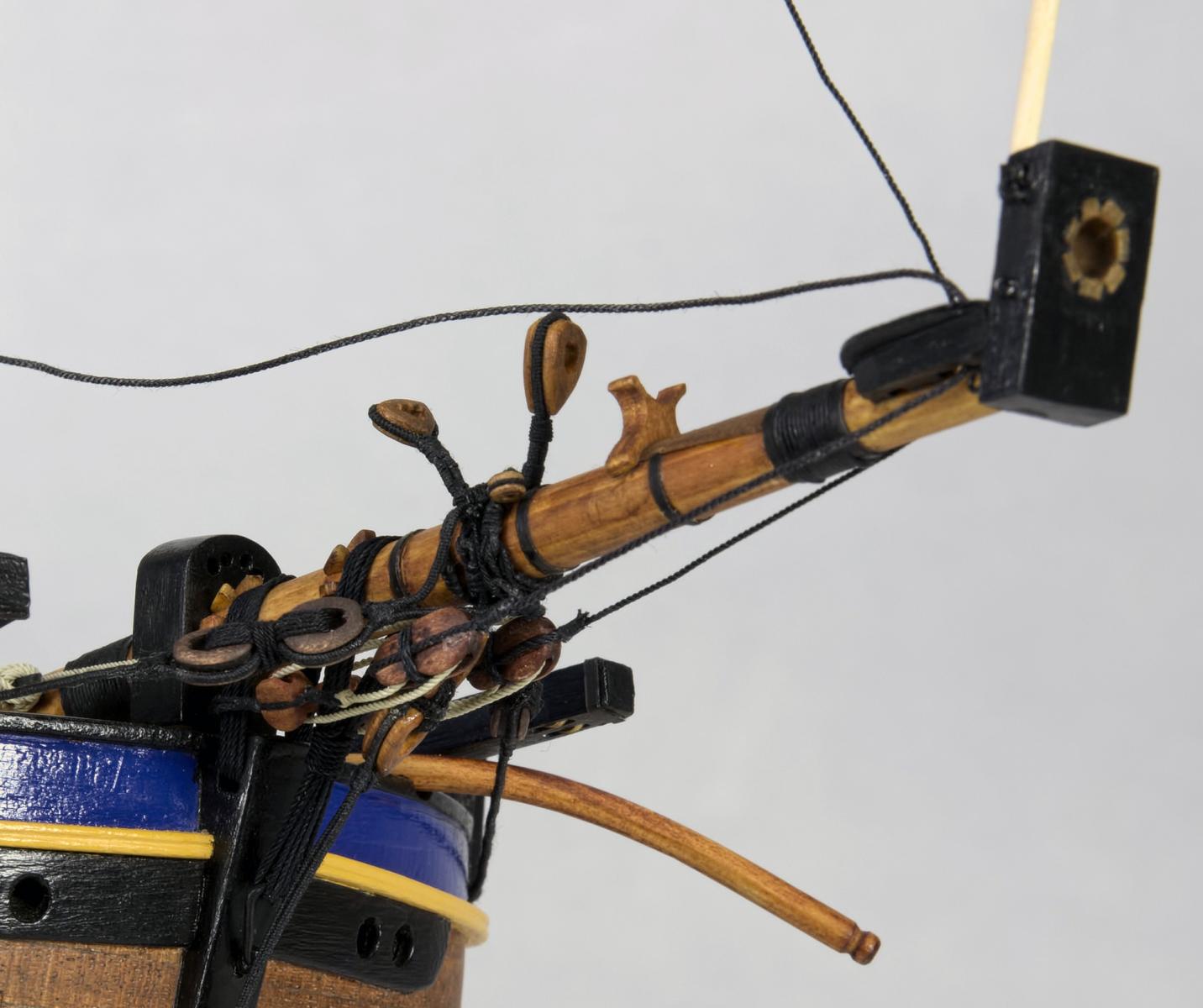
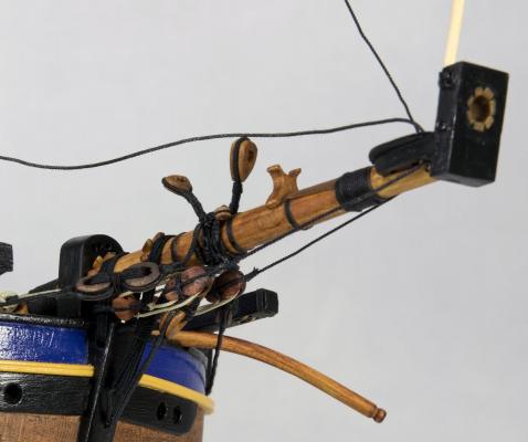
Thanks all for the positive feedback and likes; I very much appreciate you looking in. @russ - thanks mate; but you are being kind Take a look at the second photograph, the port side violin block strop has a raggedy finish to the 'fag-end' and the associated stay has some fuzz when you look at the full sized image (just to the top and left of the Bee. these were the last done and I had not checked them before fitting - but easily fixed. @jimlad - thanks John, have a little- quieter time (work and 'admiral's jobs') at the moment so I am able to spend a few more hours in the shipyard @greg lester - thanks Greg. It is a mixed bag, most of the scale rope is made by myself, but some of the running rigging is from MoRope. I can make LH laid rope quite well now (up to about 1.0 to 1.2mm dia.), but have not quite mastered RH. I use Jim Byrnes ropewalk and it is a particularly finicky (overly so) machine and you have to have everything 'just right' to get good quality rope. @mtaylor - thanks Mark, but you are being too nice . I can see some very poor workmanship on some of the very early work I did; but as this is my first serious wood ship I have been learning and improving as I go. I can definitely see some things which I just wish I had not accepted as 'acceptable' way back when cheers Pat
-
A very nicely done model Jan; a joy to look at. Your paint work is excellent with nice consistent colour and well defined edges etc. cheers Pat
-
Hi Ollie, I have poked my nose in once or twice to have a look at your build, but felt I needed to add a comment on your excellent planking and plating - your Mermaid looks nice. cheers Pat
- 803 replies
-
- 2
-
-
- colonial cutter
- modellers shipyard
- (and 1 more)
-
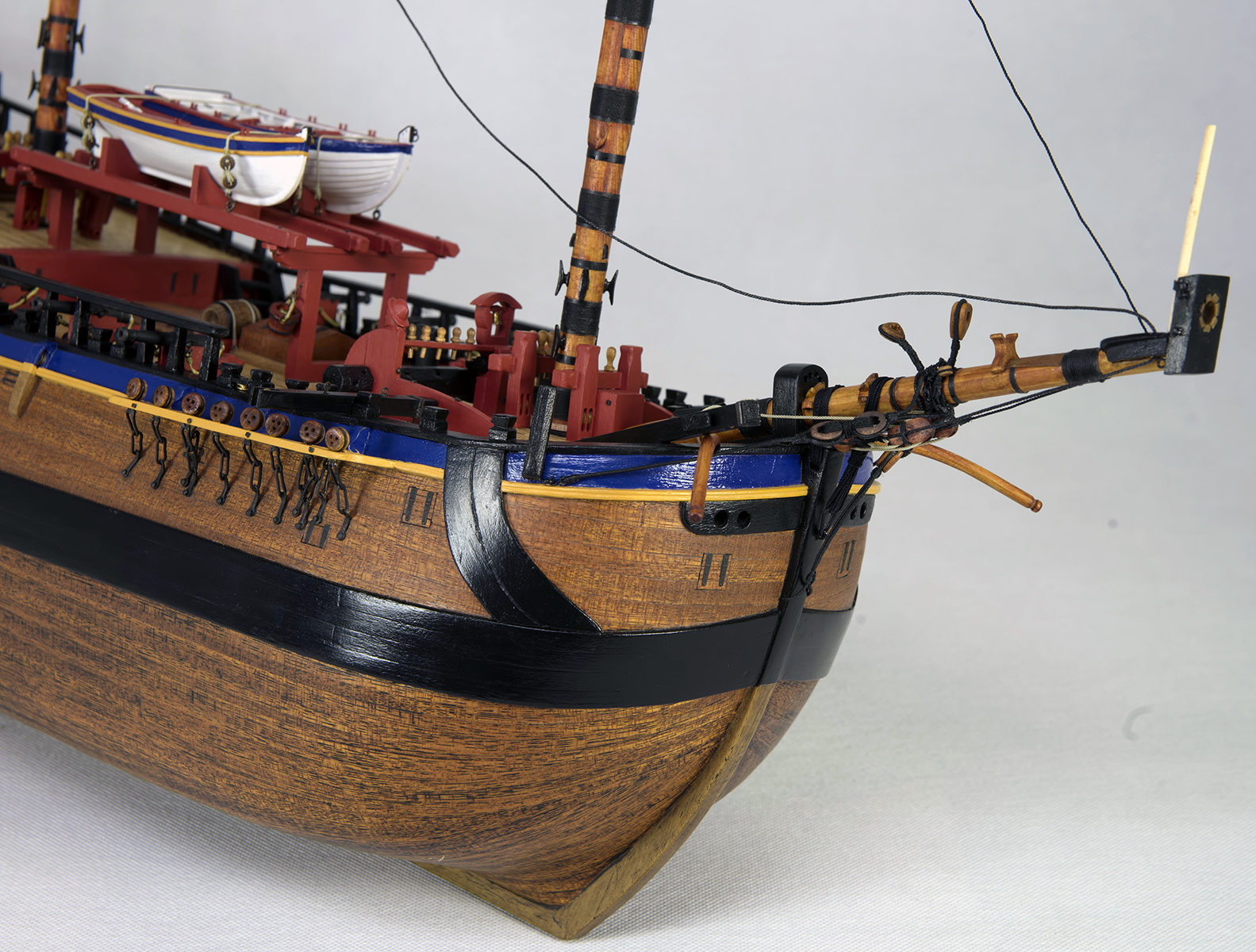
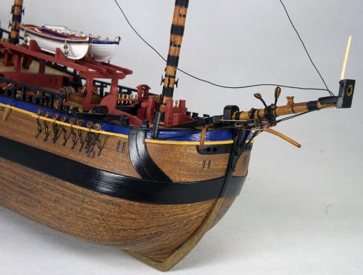
Hi folks, a small update having rebuilt the broken jib and doing some repairs. In the interim I have made the gaff, and started the standing rigging for the jib and mizzen mast. The close up photos have been sharpened to show the rope and rigging detail which has highlighted some rope fuzz and raggedy ends that needs repairs. Unfortunately this photo process also shows all the dents etc in the wood and exposed a few paint touch-ups that are required ( a good thing I suppose ) All comments and constructive criticism appreciated. cheers Pat
- 517 replies
-
- 9
-
-
- Endeavour
- Artesania Latina
- (and 1 more)
-
Remco, that is absolutely superb detail at that scale even if you are playing around as you say - you are a very talented artiste! cheers Pat
- 1,215 replies
-
- 1
-
-
- sloop
- kingfisher
- (and 1 more)
-
Nice catch Mark. I always find a book by an expert user for each of the power tools I have that explains how to 'tune' them to get consistent quality /accurate cuts, finishes etc. I have top thank a mentor in my club for that sage bit of advice. ....and that reminds me about time I revisited each to ensure all is still in alignment etc cheers Pat
-
That second version looks pretty good Russ; a case of practice makes perfect cheers Pat
-
Nearly missed the start of this second version mark; glad I didn't as you have made a great start. Bit crowded in the stalls so I've grabbed a seat at the back so that I can throw peanuts cheers Pat
-
Hi Rod, the mahogany planks look fine mate. Will you be painting the silver ash (if they are silver ash, they look a bit like the cheap pale coloured veneer in the AL kits)? If you are, simply fill and sand, then paint. If not you need to decide whether you can live with them; if you can, a light sand may remove some of the pitting/chipping. I always bought more veneer than provided in the kit so that I could select the least chipped along the edge ones; sanding can be done on the edge to bevel it which can provide a tighter fit (I did that) but if not painting I run a 2b pencil along the edge to give definition. cheers Pat
- 33 replies
-
- 1
-
-
- perseverance
- modellers shipyard
- (and 1 more)
-
Cat Head dimensions
BANYAN replied to BANYAN's topic in Building, Framing, Planking and plating a ships hull and deck
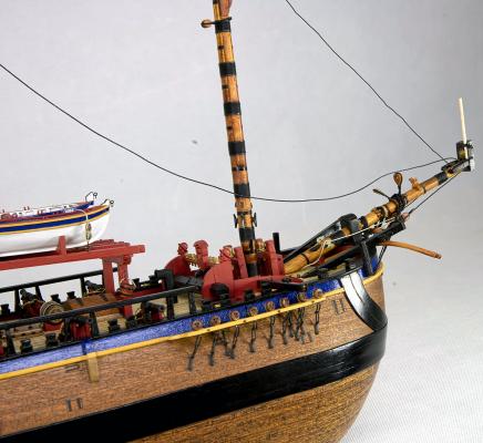
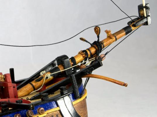
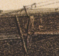
Hi Mark, The attached show the cathead 1. At launch (from a woodcut etching in the London Illustrated News) and 2. the lithograph. I am unsure what the near vertical sloping long beam aft of the cathead is, as in the litho (not shown in the woodcut) the anchor stock is clearly evident as a separate part, but the ornamentation of the knee (I think) is evident in the litho. The knee is not shown in the woodcut, but there is a rebate where it was to be fitted? cheers Pat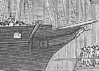
-
Cat Head dimensions
BANYAN replied to BANYAN's topic in Building, Framing, Planking and plating a ships hull and deck
Very many thanks Mark, appreciate the feedback, especially on the whiskers. As to the Cathead, last night I took the Arrow class drawings and used that as the basis for drawing Victoria's catheads. The basis of theoverall length question is that, according to Goodwin, the sheave slot length is 2 x sheave diameter. The sheave diameter is determine by 25/32 the breadth of the cathead ( which in this case I know to be 13" from the Contract records) - so 10.16" sheave diameter. The overall offset length of the cathead (so I am only considering the offset distance clear of the hull, not the overall length taking into account the cranked/canted upward slope) is 36 inches (enough to clear the anchor arm). However, by Goodwin's guidance etc, this means the overall length of 36 inches (from Arrow class), with the sheave slots ending about 13 inches from the end according to Goodwin, and each sheave slot being about 20.32" long. This would have the crown under the fish davit much further out, and the anchor shackle less than half way out along the cathead as you look down on it (all fits if the stock is canted along the sloping cathead - a la HMS Warrior - JUST!) but it sure does look strange having such long slots in such a relatively short cathead, and them being so close into the hull slots ends being just 3" out board, shackle being 13" outboard). Most other depictions of catheads I have seen do not have the slots anywhere near this big or this close to the hull. Hence the question I understand that the 20" slots would have been along the overall length which would look foreshortened in an overhead/plan view - but even so, they would still be close to the hull and looks very strange. Cheers, and thanks again for the input. Pat -
Cat Head dimensions
BANYAN replied to BANYAN's topic in Building, Framing, Planking and plating a ships hull and deck
Hi John, thanks for the feedback. I have some drawings of upward canted catheads as fitted in clippers, but only a photo of one in a warship. These are enough to create a best-guess design for the Victoria which I can use the width of the anchor arm as an indicative (or minimum) distance to place the tip from the hull. However, I was hoping there might be some guidance somewhere that naval architects may have used. if I cannot find anything more definitive I am going to use the plan view off-set distance shown for the Vigilant Class ships, but translate this to incorporate the upward cant. I am just hoping someone somewhere may have seen a rule-of-thumb or the like that stated something like anchor arm length x 1.22 or something for the off-set distance; the rest I could interpolate. I think I have tracked down almost all known drawings, lithographs, plans, photos etc of this ship and yep, a great pity the Government, Navy or other authority did not keep any significant records etc. it is almost like they washed their hands of the Victorian Colonial Navy There is only one painting that I am aware of that I do not have a copy of. I have managed to purchase copies of all known photographs, wood cut etching (London Illustrated News) and lithographs etc. The owner of the only known surviving/existing plan for the ship (single sheet as drawn by Lang and include the side profile, sheer and waterlines, and a separate drawing of the boilers) has kindly let us take a copy in return for the model to go on display in his Museum when it is completed. The other known set of plans have disappeared from the Victorian Records Office (and no, the set discussed earlier are not those ). I have also assembled every newspaper article, journal articles, magazine articles I can find, and a copy of the Geoffrey Ingleton documents, etc etc. I have also engaged a researcher in the UK whom has tracked down and provided copies of a lot of the correspondence between the various parties, authorities and family embers etc ( includes Lang, the ship's agent, overseer, Colonial office etc). She even located a folio of drawing by Lang that has proven very useful. The rest of the materials have come from searching contemporary articles, journals, records, reports, publications etc for the listed equipment and fittings stated in the Contract. I have also had some very useful help from a historian and author whom has done a lot of research on the history of the ship, but not the ship itself. I am reasonably confident, or may dare venture, that at this stage I probably have the most complete collection of information about this ship in existence (by that I mean all collected together - there is nothing new) . I am currently trying to draw up a series of deck arrangement and profile plans/illustrations to build a representative model, but as no formal deck arrangement drawings have been found - this is at best "A Best Guess" . I will need to get someone with a little more talent to make them presentable though! I will be donating the information collected to an interested party on completion, probably either the Australian War Memorial or Navy Heritage Centre, but as the Naval heritage/history people do not seem to rate this ship it will probably be the earlier cheers Pat p.s. The hull has been built, we are making and fitting the screw and then onto the deck planking - so hint taken and implemented -
Cat Head dimensions
BANYAN replied to BANYAN's topic in Building, Framing, Planking and plating a ships hull and deck
Hi Modeler12, as indicated above I am researching the HMCSS Victoria, a steam screw sloop (gun vessel) built for the Colony of Victoria in Limehouse in late 1855. The contract stated 13" sided and moulded (square) timber for the cat head but that is all. She was designed as a one off ship by Oliver W Lang and had very similar design characteristics as contemporary RN ships (Gun Vessels) of her time. In particular the Arrow class (1854) and Vigilant class (1856). I have the NMM plans for those classes but they do not depict whether they had the canted cat head design. As a one -off ship design, to be used as a warship and as a type of armed Yacht for transporting dignitaries, she had an opulent fit-out but the fluid lines of a clipper. She was fitted with the absolute latest fittings at the time taking the best from the Naval and mercantile design worlds. See: http://www.cerberus.com.au/hmcs_victoria.html and http://en.wikipedia.org/wiki/HMVS_Victoria_(1855) and https://sites.google.com/site/whowasoliverlang/h-m-v-s-victoria The lithograph I have shows a canted design with a supporting knee very similar to that in use in clippers at the time, but also as shown in the HMS Warrior (1860) link provided above. cheers Pat -
I am hoping the more experienced modellers here may have an answer to a question about the dimensions of the cat head that I have been trying to resolve for awhile. From the contract documentation I have been able to determine that the cat head sided and moulded dimensions were 13 inches (square) which ties in with other literature I have read. From a reasonable lithograph, and interpreting the other literature such as Goodwin, the most likely design for the cat head would have been the upward canted design as evidenced in HMS Warrior (contemporary to the ship I am researching - HMCSS Victoria). The following link shows this design with the upward canted cathead and knee support. http://www.stvincent.ac.uk/heritage/warrior/anchor.html What I have not been able to find is a rule of thumb, or formula that determines the length of the Cat Head overall - I have found the formula for the knee in Goodwin and one for the Cat Tail (also in Goodwin). I am assuming that the overall length of the 13" square timber would have been determined by the angle of the cant and ensuring sufficient clearance from the ship's side for the anchor not to strike/foul on her sides when catted. Is there any rule of thumb / formula for determining this length, or at least some guidance on what offset distance (from the hull) to use? A related question, is the fitting of whiskers, again stipulated in the Contract and indistinctly shown in the lithograph. From 'The Kedge Anchor' I understand that these were the iron outriggers with sheaves, fitted to the cathead, which had guys reeved through them to set up the fore chains. I am trying to determine at what sort of angle (direction and length) these protruded? Can anyone point me to a reference or provide a clearer understanding please? cheers Pat
-
One day my joinery and timberwork may be as clean as yours, but I have a long way to go. cheers Pat